Article

Study on the Optimization and Improvement of Control Strategies for Modular Multilevel Converter High Voltage Direct Current Connected to Weak Alternative Current Systems

by
Wankai Yang
1,*,
Guoliang Zhao
1 and
Dongming Han
2
1
Department of Power Electronics Technology, China Electric Power Research Institute, Beijing 100192, China
2
State Grid Electric Power Engineering Research Institute Co., Ltd., Beijing 100069, China
*
Author to whom correspondence should be addressed.
Energies 2025, 18(11), 2984; https://doi.org/10.3390/en18112984
Submission received: 22 April 2025 / Revised: 15 May 2025 / Accepted: 20 May 2025 / Published: 5 June 2025
(This article belongs to the Special Issue Planning, Operation, and Control of New Power Systems)

Abstract

:
To address the stability problem related to grid-connected modular multilevel converter high voltage direct current (MMC HVDC) connected to weak alternative current (AC) systems, the short-circuit ratio (SCR) that affects the stability of the system was analyzed first. Short-circuit ratios with SCR values greater than 1.3 were obtained, and the system could still operate stably. By applying the theoretical equations of classical circuits, it has been theoretically proven that for the constant active power and constant AC voltage control modes on the weak system side, after the flexible direct current enters the weak system mode, the power must be reduced to ensure the stable operation of the system. Combined with the actual situation of the north channel of the Chongqing–Hubei back-to-back MMC HVDC project, which is connected to the weak system mode, measures such as the optimization of the control mode and the improvement of control functions in the weak system mode were proposed, and simulation calculations and real time digital simulator (RTDS) simulation verifications were carried out. These control strategies have been applied to the Chongqing–Hubei MMC HVDC project, and on-site verification tests have been conducted to ensure stable operation in the weak system mode.

1. Introduction

Modular multilevel converter (MMC-HVDC) technology has been applied in fields such as the grid connection of distributed generation, power supply for isolated islands, power supply for urban power grids, and the interconnection of asynchronous AC power grids. It does not cause commutation failure and has the ability to supply power to weak AC systems [1]. The strength of the AC system connected to the MMC-HVDC determines the dynamic characteristics of the DC transmission system and the stability characteristics of the AC system. When there is an N-2 fault or an N-1 fault in the Chongqing-side power grid of the north channel of the Chongqing–Hubei back-to-back flexible DC transmission project, there will be a situation in which the weak AC system with a short-circuit current of 3.0 kA and 1.7 kA operates with flexible DC, resulting in the flexible DC entering the weak AC power grid, resulting in a system short-circuit ratio SCR of less than 1.3. When the MMC-HVDC is connected to an AC weak power grid, the MMC HVDC controller may cause the MMC HVDC system to lose stability, and this trend becomes more obvious with the weakening of the AC system [2]. Most studies focus on the control system aspects of the MMC-HVDC. Studies [3,4,5] analyze the limitations of MMC access to weak AC systems; when the AC system short-circuit ratio is very low, the dq axis decoupling of the MMC current vector control system fails, resulting in instability in the MMC control system. Reference [6] adopts synchronous power control, specifically a grid-forming control mode, and the MMC-HVDC can operate stably when it is connected to weak systems. Reference [7] also shows that when the short-circuit ratio SCR = 1, the two-level grid-following-type flexible DC converter can still operate stably when it is connected to a weak system, but there is no theoretical proof or project application.
The two side converters of the Chongqing–Hubei back-to-back MMC HVDC project are both grid-following-type converters that were put into operation in 2019. The method proposed in reference [6] could not be applied to the project in 2019. The method proposed in reference [7] has neither theoretical proof nor an MMC HVDC project application. Based on the actual situation of the weak system connected to the Chongqing side of the north channel at that time (when it was put into operation in 2019), this paper analyzes the stability and control adaptability of the weak system connected to the flexible DC. In view of the way the weak system appears on the Chongqing side, by applying the classic circuit equation, it has been theoretically proven that the control mode of constant power and constant AC voltage on the weak system side is superior to the control mode of constant power and reactive power. It has also been theoretically proven that after the flexible direct current enters the weak system mode, the power must be reduced to ensure the system’s stable operation. For the flexible direct current project, which adopts MMC HVDC technology, it has been theoretically analyzed and concluded that when the MMC HVDC is applied to a weak system, the system can operate stably when the short-circuit ratio is greater than 1.3. The validity of the proposed MMC HVDC control strategy was verified through simulation calculation and RTDS simulation and field tests, thereby ensuring the stable operation of the Chongqing–Hubei MMC HVDC project in the weak system mode.

2. Stability Analysis of an MMC HVDC Connected to a Weak System

2.1. Influence of the Short-Circuit Ratio on Transmission Power

In HVDC transmission technology, the impact of DC access on the system is often measured by using the short-circuit ratio (SCR) to determine the strength of the AC power grid in the AC/DC system [8]. SCR is defined as the ratio of the short-circuit capacity, Sac, of the AC bus of the converter station to the rated power, PdN, of the DC transmission system. If the reference voltage of the AC system is the rated voltage, Uc, of the AC bus of the converter station, the rated DC power, PdN, is the reference power, and the reference impedance is Zs, the short-circuit ratio can be expressed as follows:
S C R = S a c P d N = U c 2 P d N Z s = 1 Z s ( p u ) ,
For conventional DC transmission systems, reference [6] divides the strength of AC systems into the following categories: very weak system (SCR < 2), weak system (2 < SCR < 3), and strong system (SCR > 3). For the MMC HVDC transmission system shown in Figure 1, if the influence of the equivalent resistance of the AC system is ignored (i.e., Zs = jXs, impedance angle φ = 90°), β = 0, the active power, P, transmitted between the AC system and the point of common coupling (PCC) is as follows:
P = E U i X s sin α 1 X s sin α = S C R sin α
where α is the phase difference between the AC voltage, Ui, at the PCC point and the equivalent AC system voltage, E, and E and Ui are approximately equal to 1.
It can be seen in (2) that when the equivalent impedance, Zs, is small, the coupling effect between the AC system and the DC system is strong, and the ability to resist fault and interference is strong, then the AC system is a strong system, indicating that the system is relatively stable. If the AC/DC system connection is weak, the stability of the system is weak.
Ignoring the equivalent resistance of the AC system, assuming that the system is at the rated operation power point, that is, the amplitude of E and Ui is approximately 1.0 pu, the following formula is obtained:
P max =SCR
It can be seen in Formula (3) that the maximum active power value that can be transmitted between the AC system and the PCC point is the short-circuit ratio of the PCC point. Therefore, the following preliminary conclusion can be drawn: in the MMC HVDC transmission, regardless of the equivalent resistance of the AC system, the minimum SCR value of the AC system strength of the MMC HVDC converter must be 1 or greater than 1 in the rated operating state. Ref. [9] points out that when the MMC HVDC converter is connected to the weak AC system, the maximum transmission power of the converter-applied vector control is only 0.4 pu; however, there is no detailed theoretical derivation or demonstration. The research shows that the MMC HVDC has more advantages than traditional HVDC in the application scenarios of supplying power to low-SCR AC systems. However, when the MMC HVDC is connected to the low SCR AC system, a short-circuit ratio greater than 1.3 should be maintained, and the power reduction mode should be adopted, so that the system can operate stably.

2.2. Influence of the Short-Circuit Ratio on AC Voltage Fluctuation

AC system voltage fluctuation is determined using the following formula:
Δ U U = Δ Q S a c
From Formula (1), the following equation can be obtained:
Δ U U = Δ Q S a c = Δ Q P d N S C R = Δ Q S C R
It can be seen in the formula above that the voltage fluctuation is inversely proportional to the short-circuit ratio, indicating that the greater the short-circuit ratio of the MMC HVDC access AC system, the smaller the voltage fluctuation of the system.

2.3. The Relationship Between the Short-Circuit Ratio and the Moment of Inertia

When DC is connected to an AC system, the mutual influence between DC and AC depends on the relative size of the AC short-circuit capacity and the DC system capacity. On the one hand, it is the equivalent impedance of the AC system at the DC connection point; on the other hand, it is the mechanical inertia or rotational inertia of the system. The short-circuit ratio (SCR) is used to measure the magnitude of the equivalent impedance, while the inertia constant is used to measure the mechanical inertia. That is, the intensity of an AC system can be characterized by the equivalent impedance of the system and the mechanical inertia. The stability performance of voltage and frequency in an AC system is related to the mechanical moment of inertia of the AC system [10]. After the flexible DC is connected to the weak AC system, it can play the roles of rapidly regulating the flexible DC, using power modulation to dampen frequency fluctuations, providing emergency power support from the strong grid to the weak grid, and ensuring the frequency stability of the weak grid. This paper focuses on conducting an analysis and research on the stability of the system frequency.

3. Influence of the MMC System Control Mode on System Stability

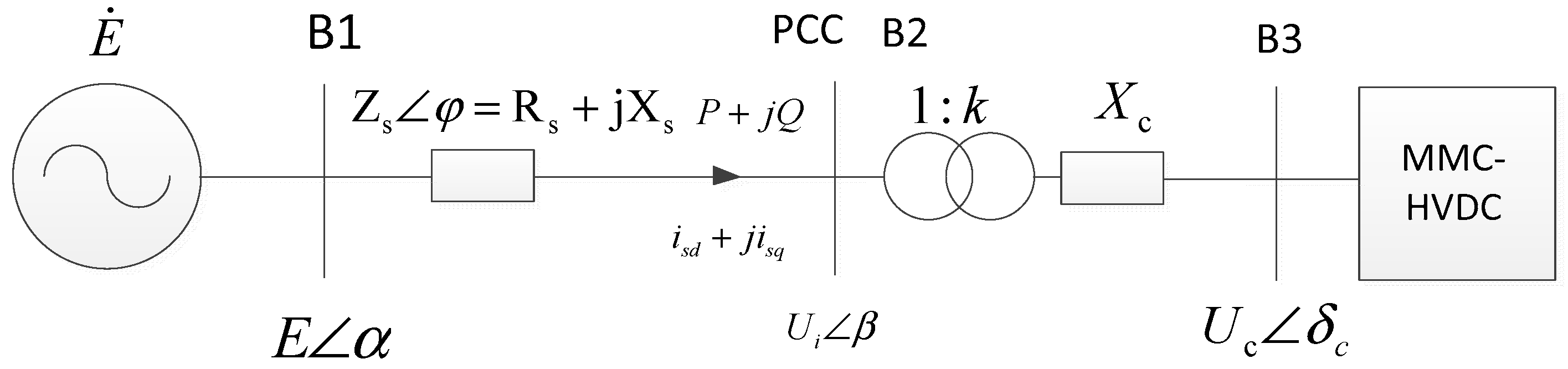
3.1. Steady-State Flow Equation

For the simplified system shown in Figure 1, the apparent power of the PCC point on the MMC HVDC AC side is as follows:
S p c c = U i I * = U i E * U i * Z * = P + j Q
In the equations, E = Ecosα + jEsinα, Z = Zcosφ + jZsinφ, and Ui = Uicosβ + jUisinβ. The following equations of power flow are obtained from Equation (6):
E U i cos(αβ)=PZ cos ϕ +QZsinϕ+ U i 2
E U i sin(αβ)=PZsinϕQZcosϕ
Assuming that β = 0 and φ = 90°, we obtain following from Equations (7) and (8):
P 2 + ( Q + U i 2 / X ) 2 = ( U i E / X ) 2
By converting to the valve side of the converter transformer, the following formula is obtained:
P 2 + ( Q + k 2 U i 2 / X ) 2 = ( k 2 U i E / X ) 2 P 2 + ( Q k 2 U i 2 / X c ) 2 = ( k U i U c / X c ) 2 P 2 + Q 2 = ( 3 k U i I i ) 2
From the statically stable dQ/dUi < 0 value, the following equation can be obtained:
d Q d U i = k 2 U i X X c X X c < 0
The following equation can be obtained from Equation (11):
X < X c
It can be seen in Equation (12) that the equivalent reactance of the MMC must be greater than that of the system. Only when the MMC is connected to the system can it operate stably. Specifically, when X = Xc, a weak system occurs.

3.2. The Influence of Control Mode on Stable Operation

3.2.1. Constant Active Power Control and Constant Reactive Power Control

For the sake of the convenience of this study and without loss of generality, assuming that the phase angle of B1 is β = 0 and φ = 90°, as shown Figure 1, we obtain the following equations from Equations (7) and (8):
E U i cosα=QX+ U i 2
E U i sinα=PX
The control of constant active power and constant reactive power indicates that P and Q are known, and the voltage, Ui, is found. Then, the variation range of reactive power and active power under weak system conditions is inferred backward from the obtained voltage, Ui. By combining Equations (13) and (14) and then solving the equation, we obtain the following equation:
U i = ( E 2 2 X Q + E 4 4 E 2 X Q 4 X 2 P 2 2 ) 1 2
If Equation (15) has a real solution, it must satisfy the following equation:
E 4 4 E 2 X Q 4 X 2 P 2 0 E 2 2 X Q + E 4 4 E 2 X Q 4 X 2 P 2 0
In order to ensure the stable operation of the system, Equation (15) should not only satisfy Equation (16) but also have the following constraints:
d U i / d Q < 0
U min U i U max
In Equation (18), Umin is generally taken as 0.95 pu, and Umax is generally taken as 1.05 pu.
Given the abovementioned conditions, when E = 1 and X = 1, specifically, when the MMC is connected to a weak system, the following formula is obtained:
1 4 Q 4 P 2 0
It can be seen in Equation (19) that when Q = 0, the following formula is obtained:
0 P 0.5 p u
It can be seen in Equation (20) that when the converter is connected to a weak system, the MMC HVDC must operate at reduced power, and in the constant active power and constant reactive power modes, the maximum power cannot exceed 0.5 pu.

3.2.2. Constant Active Power Control and Constant AC Voltage Control

If the MMC HVDC adopts constant power control and constant AC voltage control methods, then P and Ui are the control quantities. By combining Equations (13) and (14) and eliminating the power angle, the following equation is obtained:
Q = E 2 U i 2 P 2 X 2 U i 2 X
Research [11] shows that when E = 1, the following equation can be obtained:
S C R > 1.238
When Equation (22) holds, the connection of MMC HVDC to the AC system will not affect the stability of the system. Based on the results of Equation (22), this paper concludes that the system with an SCR value greater than 1.3 can operate stably, which aligns with reference [12].
Based on the research results of reference [13], the following formula can be obtained:
Q X 0.4 p u
P X 0.8 p u
When X = 1, the MMC HVDC is connected to a weak system, and the maximum transmission power is 0.8 pu. This once again proves that the MMC HVDC must operate at reduced power when connected to a weak system. Meanwhile, Equation (24) also proves that when the MMC HVDC is connected to a weak system and the control mode of constant active power and constant AC voltage is adopted, the transmission power of the MMC HVDC is greater than that of the control mode of constant active power and constant reactive power, which is conducive to the stable operation of the MMC HVDC system.

3.2.3. Constant DC Voltage Control and Constant Reactive Power Control

When analyzing the steady-state safety constraints of the converter in the control mode of constant reactive power and constant DC voltage, the controllable variable becomes the DC terminal voltage of the MMC HVDC, and it is necessary to transfer the controllable variable (DC voltage) to the AC side of the MMC HVDC. As shown in Figure 1, the equation of the current is as follows:
k U i U c sin δ = P i X c k U i U c cos δ = k 2 U i 2 Q i X c
k U i U c sin δ = P c X c k U i U c cos δ = U c 2 + Q c X c
U c = M 3 2 U d
i—The position of the converter AC busbar.
c—Input position of the converter valve.
d—The position of the converter DC side.
Ud is the DC side voltage of the converter and M is the modulation coefficient of the converter.
In Equation (27), M is the modulation coefficient of the converter. Under the static stability conditions satisfying Equations (17) and (18), referring to the relevant reference [13], the following equation is obtained:
Q < k 2 X c P 1 k 4 X c 2
It can be seen in Equation (28) that when constant DC voltage control and constant reactive power control are adopted on the strong system side and the reactive power absorbed by the MMC HVDC converter from the strong system side is less than k2/Xc, the DC voltage Ud of the converter can be stable. The strong system side can stabilize Uc on the weak system side, and the constant AC voltage control of the weak system can stabilize Ui changes, thereby enabling the MMC HVDC system’s stable operation.

4. The Influence of MMC HVDC Connected to Weak Systems on the Converter Control

4.1. The Phase-Locked Control Is Inaccurate

In weak systems, the voltage at the busbar of the converter station fluctuates greatly. The inherent control delay of the phase-locked loop makes it unable to closely track the phase changes. According to the small-signal model analysis of the MMC HVDC system in reference [14], the state model of the MMC HVDC system with a phase-locked loop (PLL) was obtained. When the SCR of the AC power grid is less than 1.32, the stability performance of the system will be affected by the PLL. When the SCR of the AC power grid is less than 1.24, the MMC HVDC system with the PLL will not be able to operate stably, which basically aligns with the mathematical derivation of Equation (22).

4.2. The Inner Loop Control Is Unstable

When MMC-HVDC is connected to the weak AC power grid, the system impedance, Xs, is relatively large. The control of active power and reactive power cannot be completely decoupled. The Q-axis current has a significant impact on the output active power, and the D-axis current has a significant impact on the output reactive power and terminal voltage. This results in the active power, reactive power, and terminal voltage amplitudes of the MMC-HVDC system being controlled by the D-axis current and the Q-axis current, which are coupled with each other. Reference [15] proposed that adding a dynamic feedforward compensation decoupling strategy to the inner loop current control can enhance the decoupling characteristics of the system compared with the static feedforward compensation decoupling strategy and the traditional vector current control strategy. However, when the active power command value and the reactive power/voltage command value change, an unstable positive feedback loop will be formed between the active power control and the inner loop current control, resulting in system instability.

4.3. The Control Mode and Parameters of the MMC HVDC Do Not Meet the Operation Conditions

  • The AC system voltage at the PCC point of the MMC-HVDC-connected system is more sensitive to fluctuations in the MMC transmission power. Therefore, the MMC HVDC’s access to the weak system side adopts AC voltage control, and the control parameters need to be optimized too.
  • After the MMC HVDC is connected to the weak system, due to the change in the structure of the AC power grid, the system changes from strong to weak, that is, the SCR decreases. As a result, the original decoupling control of active and reactive power will become uncertain. To adapt to the instability of the MMC HVDC system operation caused by the change in the structure or mode of the system power grid, the control system needs to have the ability to switch between different operation modes.

4.4. The Control Strategy Adopted by the MMC HVDC Entering the Weak System

Based on the analysis results of the first, second, and third sections mentioned above, when the MMC HVDC is directly applied to a weak AC system, the following aspects need to be noted:
  • The AC system voltage at the PCC point of the MMC-HVDC-connected system is more sensitive to fluctuations in the flexible DC transmission power. Therefore, the flexible DC access to the weak system side adopts AC voltage control.
  • When the MMC HVDC is connected to a weak AC system, the magnitude of its short-circuit ratio SCR will have an impact on the maximum transmission power. Therefore, for MMC HVDC control, it is necessary to select an appropriate control strategy based on the conditions of the AC system. The MMC HVDC transmission power is limited and rapidly reduced. The MMC HVDC control strategy and parameter optimization should be carried out to improve the operational stability of the flexible DC and avoid unstable conditions in the system.
  • After the MMC HVDC is connected to the system, due to the change in the structure of the AC power grid, the system changes from strong to weak, that is, the SCR decreases. The original decoupling control of active and reactive power will then become uncertain. To adapt to the instability of the MMC HVDC system operation caused by the change in the structure or mode of the system power grid, the control system needs to have the ability to switch between different operation modes. By detecting the changes in the power grid structure, an instruction to switch to the weak system operation mode is issued.

5. Improvement of the Control Strategy and Simulation/Experimental Verification

5.1. Overview of the Weak System of the Chongqing–Hubei MMC HVDC Project

The north channel of the Chongqing–Hubei back-to-back MMC HVDC project has a rated voltage of ±420 kV and a rated power of 2500 MW. Two converters operate in parallel, each with a rated power of 1250 MW, and can operate independently. The Chongqing side is connected to the Chongqing power grid through two 500 kV lines from Chongqing Jiupan to Hubei Yichang, with a line length of 230 km. A series compensation device is installed near the Jiupan side of the line. The intensity of the AC system is relatively weak, and the short-circuit current is at a relatively low level. When there are N-2 faults in different components or N-1 faults in the maintenance mode of the near-area lines, series compensation, and generator units, the short-circuit current on the system side will be lower than the boundary conditions determined in the project feasibility study stage, and the Chongqing side will access weak system mode. Reference [13] provides detailed system calculations, which will not be elaborated here. The power grid structure diagram on the Chongqing side is shown in Figure 2.
According to system calculations and analysis [13], during normal operation, the short-circuit current on the Chongqing side of the Chongqing–Hubei flexible direct north channel is greater than 5 kA, and the AC voltage on the Chongqing side is 525 kV. The system short-circuit ratio is as follows:
S C R = S a c P d N = 3 × 525 × 5 2500 = 1.81
When the Chongqing side turns into a weak system due to changes in the power grid structure, the short-circuit current is below 3 kA [13], and the short-circuit ratio of the weak system is as follows:
S C R = S a c P d N = 3 × 525 × 3 2500 = 1.091
In the analysis above, it can be seen that when the short-circuit ratio on the Chongqing side is less than 1.091, the flexible DC must be switched to the weak system operation mode, and the corresponding control strategy and control parameters also need to be changed to maintain the system’s stable operation.

5.2. Improvement of the Control Strategies and Optimization of the Control Modes

5.2.1. Phase-Locked Loop Control

Relevant studies have shown [16] that under weak system conditions, phase-locked loop control affects the stable operation of the MMC system. Under the condition of being converted to a weak system, both the phase-locked loop control and the virtual synchronous control of the Chongqing–Hubei MMC north channel can achieve reliable phase angle locking. Through simulation calculation and experimental verification, the system can still operate stably when the short-circuit current is as low as 1.5 kA (weak system).

5.2.2. Outer Loop Control

Under normal operation and strong system conditions, a dead zone is set for constant AC voltage control to avoid frequent adjustments of reactive power when there are small disturbances in the AC voltage. When the Chongqing side of the Chongqing–Hubei MMC north channel project turns into a weak system, adjusting the original voltage control dead zone from ±7 kV to 0 kV can enable the reactive power support capacity to be exerted rapidly to enhance the reactive power support capacity, smooth out voltage fluctuations, and reduce the duration of the transition process. Meanwhile, a weak system emerged on the Chongqing side, forcing the reactive power control to change to a constant AC voltage control mode. The parameters of the AC voltage control loop were adjusted (from kp = 0, ki = 4 to kp = 2, ki = 10).

5.2.3. Inner Loop Control

When a weak system occurs on the Chongqing side of the Chongqing–Hubei MMC HVDC north channel project, the current inner loop gain, kp, increases from 0.3 to 0.4, which improves the control performance of the current inner loop and is conducive to the stability of the flexible direct control system under weak system conditions.

5.2.4. Control Mode Optimization

Under the normal operation conditions of the system, the SCR of the systems on both sides of the Chongqing–Hubei MMC HVDC project north channel is greater than 3, which indicates a strong system. When the Chongqing side switches to a weak system, it switches to power control and AC voltage control mode, while the Hubei side switches to constant DC voltage control and reactive power control mode. The stability of the DC voltage controlled by the strong system is higher. The stable DC voltage, through the AC-DC conversion link, can indirectly promote the stability of the AC voltage on the weak system side.

5.3. Simulation Calculation and Experimental Verification

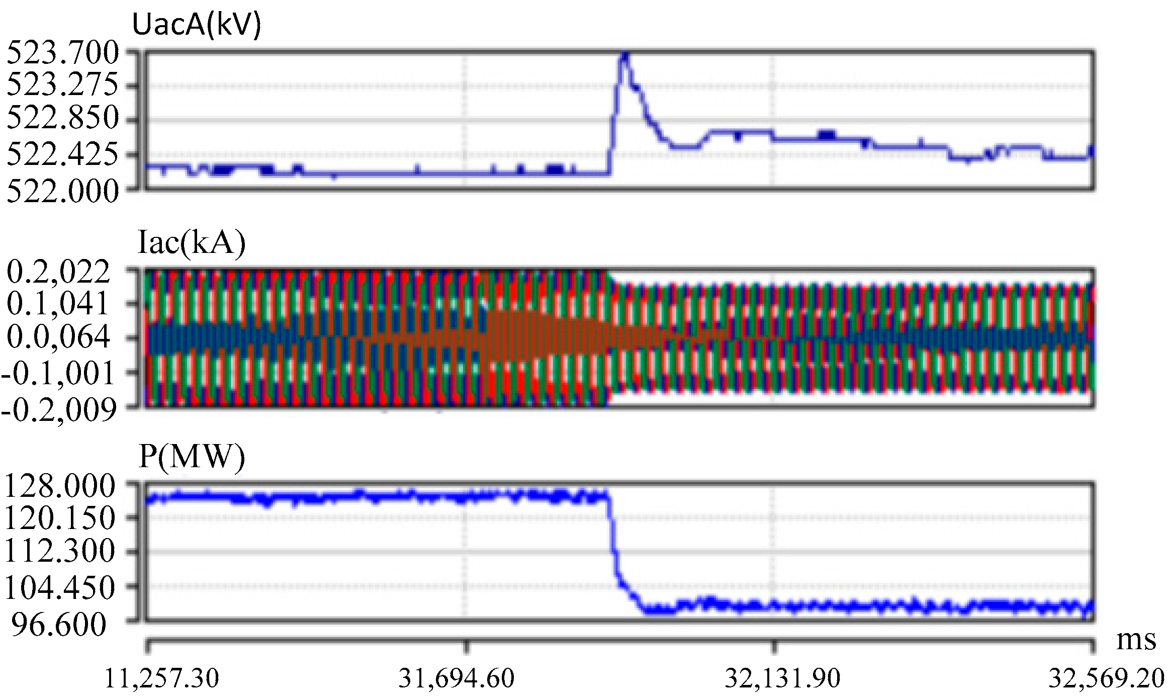
5.3.1. Simulation Calculation

In order to verify that the MMC HVDC control strategy can ensure the stable operation of the system under weak system conditions, a simulation calculation model of the Chongqing–Hubei MMC HVDC north channel project was established using PSCAD. The equipment and control protection parameters were exactly the same as those of the project. The simulation results are shown in Figure 3 below.
As shown in Figure 3, when transmitting power 500 MW (low power), without changing the control strategy, a three-phase grounding fault is simulated, and the flexible DC system recovers to normal operation relatively slowly. After adopting the weak system optimization control strategy and operating at low power to simulate three-phase instantaneous grounding faults, the system recovers stable operation relatively quickly.

5.3.2. RTDS Simulation Test

In order to further verify the control strategy of the Chongqing–Hubei flexible DC system after it is connected to the weak system, a simulation test model was established on the RTDS. The main circuit adopted the RTDS model, and the control and protection functions used the project control and protection device. A real-time simulation test was completed, and the simulation test results are shown in Figure 4 below.
It can be seen in Figure 4a that after the MMC HVDC enters the weak system mode, if the control strategy remains unchanged, the converter valve will trip, blocking the MMC HVDC when the system recovers after a fault. It can be seen in Figure 4b–d that when the converter control strategy and parameters are optimized, the system can resume stable operation after an AC fault. Figure 4e shows that when the flexible DC system operates at high power and is transferred to the weak system mode, the power transmitted by the converter is limited and rapidly drops, and the system resumes stable operation.

5.3.3. Field Test

Through the above mentioned simulation calculation and simulation experiment research, the control strategy of the MMC HVDC in the weak system mode was obtained. These control strategies were applied to the Chongqing–Hubei MMC HVDC back-to-back project and were verified through on-site tests. The process is as follows: The flexible DC dual converter units are in operation. The DC power from the Chongqing side to the Hubei side is 250 MW. A situation in which all the units of the Henglu power plant are out of operation is simulated, and the Chongqing side switches to the weak system mode. The DC power drops rapidly by 100 MW, and each converter unit reduces power by 50 MW. The voltage, current, and transmission power of the converter unit I on the Chongqing side are shown in Figure 5.
As can be seen in Figure 5 above, after the Chongqing side entered the weak system mode, the DC power was restricted and rapidly decreased, and the system resumed stable operation.

6. Conclusions

The system stability problems existing in the MMC-HVDC connected to the weak AC power grid system were analyzed. The influence of the size of the system’s short-circuit ratio for evaluating system stability on the system was analyzed. The control mode and the adaptability of control functions in the weak system mode were studied. The optimization measures of the control strategy were proposed and verified through simulation calculation and RTDS simulation and field tests. The following conclusions were drawn:
  • Theory, simulation calculation, and experiments have proven that when the MMC HVDC is connected to a weak system, the system SCR maintains a short-circuit ratio greater than 1.3, and the power reduction mode is adopted; thus, the system can operate stably.
  • It has been theoretically proven that when the MMC-HVDC is connected to a weak system, the control mode of constant active power and constant AC voltage on the weak system side and the control mode of constant power and constant DC voltage on the strong system side are conducive to the stable operation of the system.
  • The control strategy and parameters of the MMC-HVDC system were optimized after being connected to the AC weak system. Simulation verification was carried out and applied to the Chongqing–Hubei MMC project, thereby ensuring the stable operation of the MMC-HVDC in the weak system mode.
  • In the control performance analysis of the grid-structured flexible direct access system, it can be seen that the performance of the grid-structured converter on the weak system access side is superior to that of the grid-following converter. To facilitate the normal operation of the grid-following flexible direct current system, due to special changes in the power grid structure, a weak system is occasionally connected to one side of the converter. It is still more reliable to adopt the scheme proposed in this paper.

Author Contributions

Conceptualization, W.Y.; Validation, W.Y.; Investigation, G.Z. and D.H.; Resources, D.H.; Writing—review & editing, W.Y.; Supervision, G.Z.; Funding acquisition, G.Z. All authors have read and agreed to the published version of the manuscript.

Funding

This article was supported by SGCC Science and Technology Project (5500-202358698A-3-3-JC): “Research on the Harmonics Interaction Mechanism between LCC-HVDC Converter Station and Power Grid”.

Data Availability Statement

The original contributions presented in the study are included in the article, further inquiries can be directed to the corresponding author.

Conflicts of Interest

Author Dongming Han was employed by the company State Grid Electric Power Engineering Research Institute Co., Ltd. The remaining authors declare that the research was conducted in the absence of any commercial or financial relationships that could be construed as a potential conflict of interest.

References

  1. Wang, X.; Du, W.; Wang, H. Stability analysis of grid-tied VSC systems under weak connection conditions. Proc. CSEE 2018, 38, 1593–1604. [Google Scholar]
  2. Konishi, H.; Takahashi, C.; Kishibe, H.; Sato, H. A Consideration of Stable Operating Power Limits in VSC-HVDC Systems. In Proceedings of the Seventh International Conference on AC-DC Power Transmission, London, UK, 28–30 November 2001; IET: London, UK, 2001; pp. 102–106. [Google Scholar]
  3. Zhang, L.D. Modeling and Control of VSC-HVDC Links Connected to Weak AC Systems. Ph.D. Thesis, KTH Royal Institute of Technology, Stockholm, Sweden, 2010. [Google Scholar]
  4. Zhang, L.D.; Harfors, L.; Nee, H.P. Modeling and control of VSC-HVDC links connected to island systems. IEEE Trans. Power Syst. 2011, 26, 783–793. [Google Scholar] [CrossRef]
  5. Zhang, L.D.; Harfors, L.; Nee, H.P. Interconnection of two very weak AC systems by VSC-HVDC links using power-synchronization control. IEEE Trans. Power Syst. 2011, 26, 344–355. [Google Scholar] [CrossRef]
  6. Li, T.; Lu, Q.; Sun, P.; Su, R.; Li, Z. Research on Virtual Synchronous Machine Control Strategy for Flexible DC System. Power Electron. 2025, 59, 57–61. [Google Scholar]
  7. Liang, J.; Li, C. Recent Development of Grid-connected Inverters and Weak-grid Stabilization. Power Syst. Technol. 2022, 46, 3703–3711. [Google Scholar]
  8. Xu, Z. Characteristics of HVDC connected to weak AC systems Part I: HVDC transmission capability. Power Syst. Technol. 1997, 21, 12–16. [Google Scholar]
  9. Durrant, H.W.; Abbott, K. Model of a VSC HVDC terminal attached to a weak ac system. In Proceedings of the IEEE Conference Control Applications, Istanbul, Turkey, 23–25 June 2003. [Google Scholar]
  10. Guo, X.-j.; Tang, Y.; Guo, Q.; Lin, W.F.; Bu, G.Q.; Ma, S.Y. Influence factors and theory for CIGRE MISCR index. Power Syst. Prot. Control. 2012, 40, 69–74. (In Chinese) [Google Scholar]
  11. Yang, W.; Cao, H.; Gao, C.; Cheng, Q.; Song, Y. Study on Steady-state Characteristics of MMC-HVDC Connected Weak AC System. In Proceedings of the 2023 IEEE Sustainable Power and Energy Conference, Chongqing, China, 29–30 November 2023; pp. 1299–1304. [Google Scholar]
  12. Liu, S.H.; Xu, Z.H. Study on Stable Operating Region of VSC-HVDC Connected to Weak AC Systems. Proc. CSEE 2016, 36, 133–143. [Google Scholar]
  13. Yang, W.; Zhang, S.; Yu, H.; Liu, B. System analysis and simulation experimental research of VSC-MMC HVDC connected to AC weak system. Power Syst. Technol. 2021, 45, 2457–2464. [Google Scholar]
  14. Ashabani, M.; Mohamed, Y. Integrating VSCs to weak grids by nonlinear power damping controller with self-synchronization capability. IEEE Trans. Power Syst. 2014, 29, 805–814. [Google Scholar] [CrossRef]
  15. Shao, B.; Zhao, S.; Gao, B. Instability mechanism and criterion analysis of VSC-HVDC connected to the weak AC power grid. Trans. China Electrotech. Soc. 2019, 34, 3884–3896. [Google Scholar]
  16. Zhou, J.Z.; Ding, H.; Fan, S.; Zhang, Y.; Gole, A.M. Impact of short-circuit ratio and phase-locked loop parameters on the small-signal behavior of a VSC-HVDC Converter. IEEE Trans. Power Deliv. 2014, 29, 2287–2296. [Google Scholar] [CrossRef]
Figure 1. Main circuit diagram of an MMC converter connected to AC systems.
Energies 18 02984 g001
Figure 2. Structure diagram of the Yu-side power grid in the Yu to E MMC-HVDC north channel project.
Energies 18 02984 g002
Figure 3. Simulation calculation results when exceeding the limit operation and low-power operation in weak system mode. (a) Normal control strategy: in a weak system, the transmission power exceeding the limit leads to the oscillation of the AC voltage and current. (b) Normal control strategy, 500 MW from Chongqing to Hubei, three-phase grounding instantaneous fault, converter voltage, and current waveforms. (c) Weak system control strategy, 500 MW transmission from Chongqing to Hubei, three-phase grounding instantaneous fault, converter voltage, and current waveforms. From top to bottom: Phase A voltage, three-phase current (Phase A—blue, Phase B—red, Phase C—green).
Energies 18 02984 g003
Figure 4. Simulation test results before and after the optimization of the weak system control strategy. (a) The normal control strategy, three-phase instantaneous ground fault simulation, and the system trips and blocks in the weak system mode. (b) AC voltage controller parameters under weak system conditions (kp = 2, ki = 10). (c) Control parameters of inner loop current controller under weak system conditions (kp = 0.4). (d) Control of DC voltage on the Hubei side. (e) High-power operation, weak system mode, and limited active power. Each figure, from top to bottom: Phase A voltage, three-phase current (Phase A—blue, Phase B—red, Phase C—green).
Energies 18 02984 g004
Figure 5. Test results of the rapid drop in DC power in converter unit 1 of the weak system on the Chongqing side. From top to bottom: Phase A voltage, three-phase current (Phase A—blue, Phase B—red, Phase C—green), power of converter unit 1.
Energies 18 02984 g005
Disclaimer/Publisher’s Note: The statements, opinions and data contained in all publications are solely those of the individual author(s) and contributor(s) and not of MDPI and/or the editor(s). MDPI and/or the editor(s) disclaim responsibility for any injury to people or property resulting from any ideas, methods, instructions or products referred to in the content.

