Article

A Cost-Effective and Reliable Junction-Box–Integrated Rapid Shutdown System for BIPV Applications

1
Artificial Intelligence Energy Research Center, Korea Photonics Technology Institute, 9, Cheomdanventure-ro 108beon-gil, Buk-gu, Gwangju 61007, Republic of Korea
2
Department of Future Mobility, College of AI, Chonnam National University 77, Yongbong-ro, Buk-gu, Gwangju 61186, Republic of Korea
*
Authors to whom correspondence should be addressed.
Energies 2025, 18(11), 2983; https://doi.org/10.3390/en18112983
Submission received: 29 March 2025 / Revised: 29 April 2025 / Accepted: 8 May 2025 / Published: 5 June 2025
(This article belongs to the Section A2: Solar Energy and Photovoltaic Systems)

Abstract

In response to fire safety risks associated with photovoltaic (PV) systems and evolving rapid shutdown requirements, this paper proposes a cost-effective and reliable rapid shutdown solution integrated directly into the PV module junction box. The system employs analog circuitry triggered by an external pulse-width modulation (PWM) signal, with optocoupler isolation and a controlled short-circuit method to rapidly reduce the module output voltage. Simulation and experimental results confirm that the output voltage is reduced to approximately 2 V within 280 ms, satisfying the U.S. National Electrical Code (NEC) 690.12 requirements. This junction-box–integrated approach eliminates the complexity of conventional module-level power electronics (MLPE) systems and offers a highly practical alternative for building-integrated photovoltaic (BIPV) applications where partial shading is minimal.

1. Introduction

Photovoltaic (PV) power generation has emerged as a key technology for achieving carbon neutrality, as it produces clean energy that reduces dependence on fossil fuels and helps combat climate change [1]. Despite these environmental benefits, however, the increasing adoption of solar PV systems has brought new safety challenges, particularly regarding elevated electrical risk in the event of a fire [2].
In building-integrated PV systems, it is crucial to protect the safety of residents, support effective firefighting operations, and prevent the spread of fire to adjacent buildings [3]. Yet, as long as PV modules are exposed to sunlight, they continuously produce high-voltage direct current (DC), which raises the risk of electric shock during fire suppression and rescue efforts. This poses a serious threat to both firefighters and building occupants, and if power is not rapidly shut off, additional damage can ensue.
Rapid shutdown systems have been introduced to address this issue, and National Electrical Code (NEC) 690.12 [4,5,6,7] in the United States stipulates that PV systems must be able to quickly reduce or fully disconnect voltage in emergency situations [8,9].
Over the last decade, rapid shutdown technology for building-integrated photovoltaics (BIPV) has evolved from basic string disconnects to sophisticated module-level and system-level solutions driven by stringent safety codes [10]. The string-level Rapid Shutdown Device (RSD) provided an early boost to safety but left gaps within the array. Module-level solutions filled those gaps, offering near-complete hazard elimination at the cost of more components, and became mainstream in residential and many commercial BIPV systems.
The most widely employed rapid shutdown technology to date is the Module Level Power Electronics (MLPE) approach, exemplified by microinverters and power optimizers. MLPE systems perform power conversion and optimization at the module level, thereby mitigating partial shading issues and improving energy yield [11].
Nevertheless, concerns remain regarding the actual effectiveness of MLPE systems. Although MLPE is generally considered to enhance power output under various conditions, in reality, it offers significant performance improvements primarily under specific scenarios such as when modules are installed at varying tilt angles or are subject to continuous, heavy shading [12,13]. In typical environments without partial shading, MLPE systems may actually yield lower performance compared to conventional string inverter systems [14]. This observation suggests that the proposed solution could serve as an alternative to MLPE systems in settings where partial shading is not a major concern.
While MLPE systems have become a common approach to fulfilling rapid shutdown requirements, they introduce several limitations. These systems entail high upfront costs and complex system architectures. Since each module requires an additional power con-version device, the overall component count increases, leading to a higher probability of failure and potentially greater maintenance demands. Furthermore, when MLPE devices from different manufacturers are paired with various PV modules, issues such as connector mismatches, reliability concerns, and electrical connection errors may arise. These problems not only compromise long-term system reliability but also pose significant safety risks, including potential fire hazards.
To address these challenges, a novel and cost-effective solution is necessary to ensure compliance with safety standards while reducing system complexity. This paper proposes a newly developed junction-box–integrated rapid shutdown system, which achieves module-level voltage reduction not through open-circuit disconnection, but by implementing an internal short-circuiting mechanism within each PV module. Although short circuits are generally avoided in conventional power electronic systems, in PV applications, internally shorting the module drives the output voltage toward zero effectively suppresses power generation.
By simplifying the system architecture and minimizing the number of components, this method offers a highly economical and reliable alternative for rapid shutdown applications. Specifically, the proposed system integrates the rapid shutdown function directly into the module’s junction box using a minimal analog circuit, eliminating the need for separate module-level power electronics. This design significantly reduces both cost and complexity while maintaining full compliance with NEC 690.12 requirements.
In this study, we present the design, operating principles, and implementation guidelines for the junction-box–integrated rapid shutdown system. The structure of the paper is as follows: Section 2 describes the proposed system design; Section 3 presents simulation and experimental validation results; Section 4 discusses broader implications; and Section 5 concludes the study.
Before introducing the proposed system, Section 1 provides an overview of the rapid shutdown requirements that form the basis for its design, including a summary of the update history and key provisions of NEC 690.12, the first and most widely adopted rapid shutdown standard. Additionally, global trends in rapid shutdown regulations are briefly discussed. The National Electrical Code (NEC) introduced rapid shutdown requirements for PV systems in 2014, then updated and expanded them in 2017, 2020, and 2023. Table 1 provides a concise overview of these key revisions.
NEC 690.12 specifies the technical requirements for rapid shutdown of PV systems, covering voltage limits, controlled conductor definitions, initiation device requirements, and equipment standards. The provisions summarized in Table 2 help ensure the safety of emergency responders during firefighting operations and establish a framework for designing compliant rapid shutdown systems.
Since the United States introduced rapid shutdown regulations, major countries such as the United Kingdom, Germany, Canada, and Australia have implemented rapid shutdown systems to enhance the safety of building integrated photovoltaic systems. The relevant regulations for each country are shown in Table 3 below.

2. Junction-Box–Integrated Rapid Shutdown System

The primary objective of the proposed junction-box–integrated rapid shutdown system is to provide a device with high reliability while implementing a cost-effective rapid shutdown function, thereby promoting the widespread adoption of building integrated photovoltaic systems. To this end, the system was designed to be directly integrated into the junction box, eliminating the need for additional components. Moreover, an analog approach was prioritized in the design to ensure cost reduction and reliability, with a focus on minimizing the number of components required to effectively implement the rapid shutdown functionality.

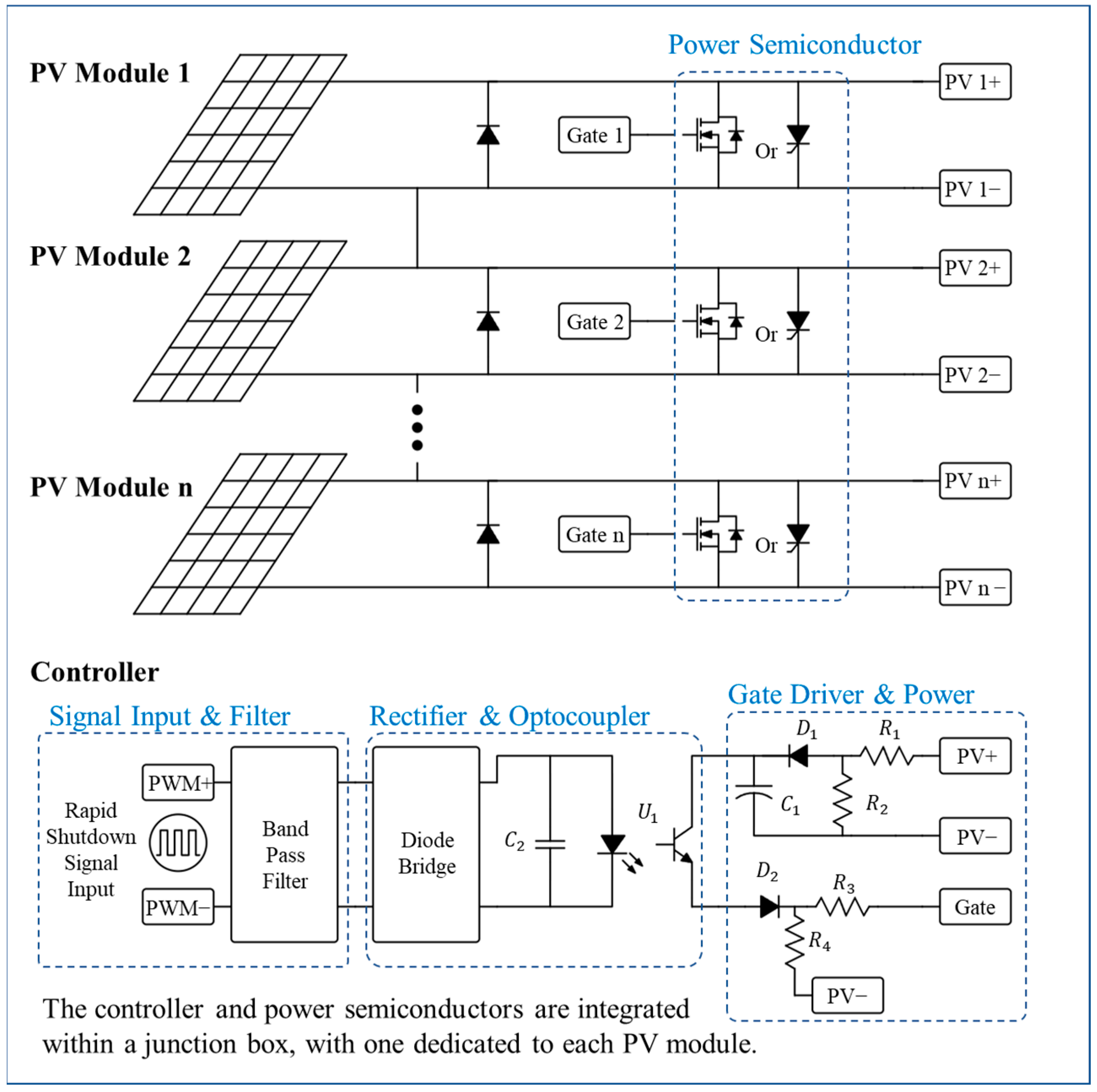
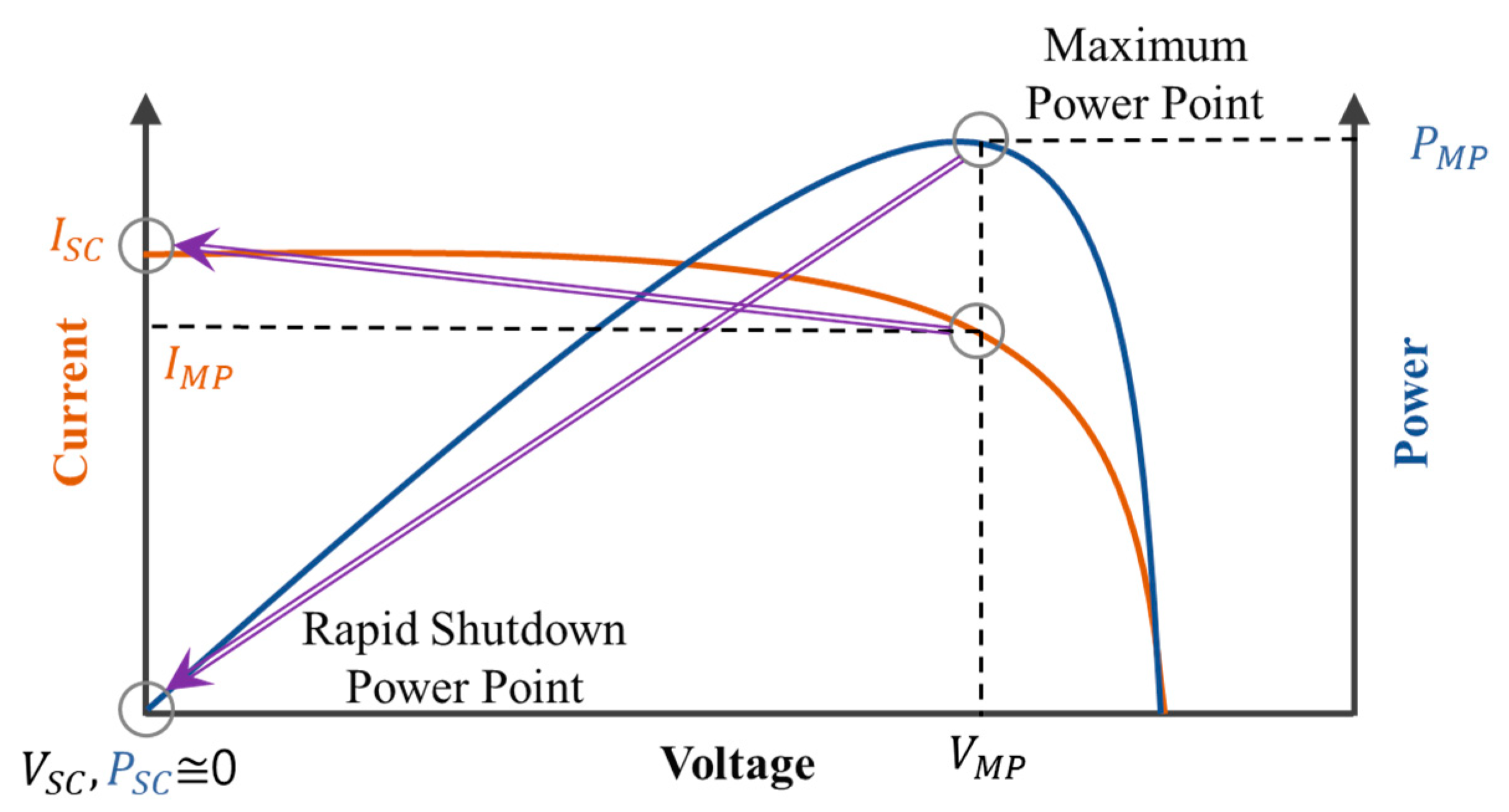
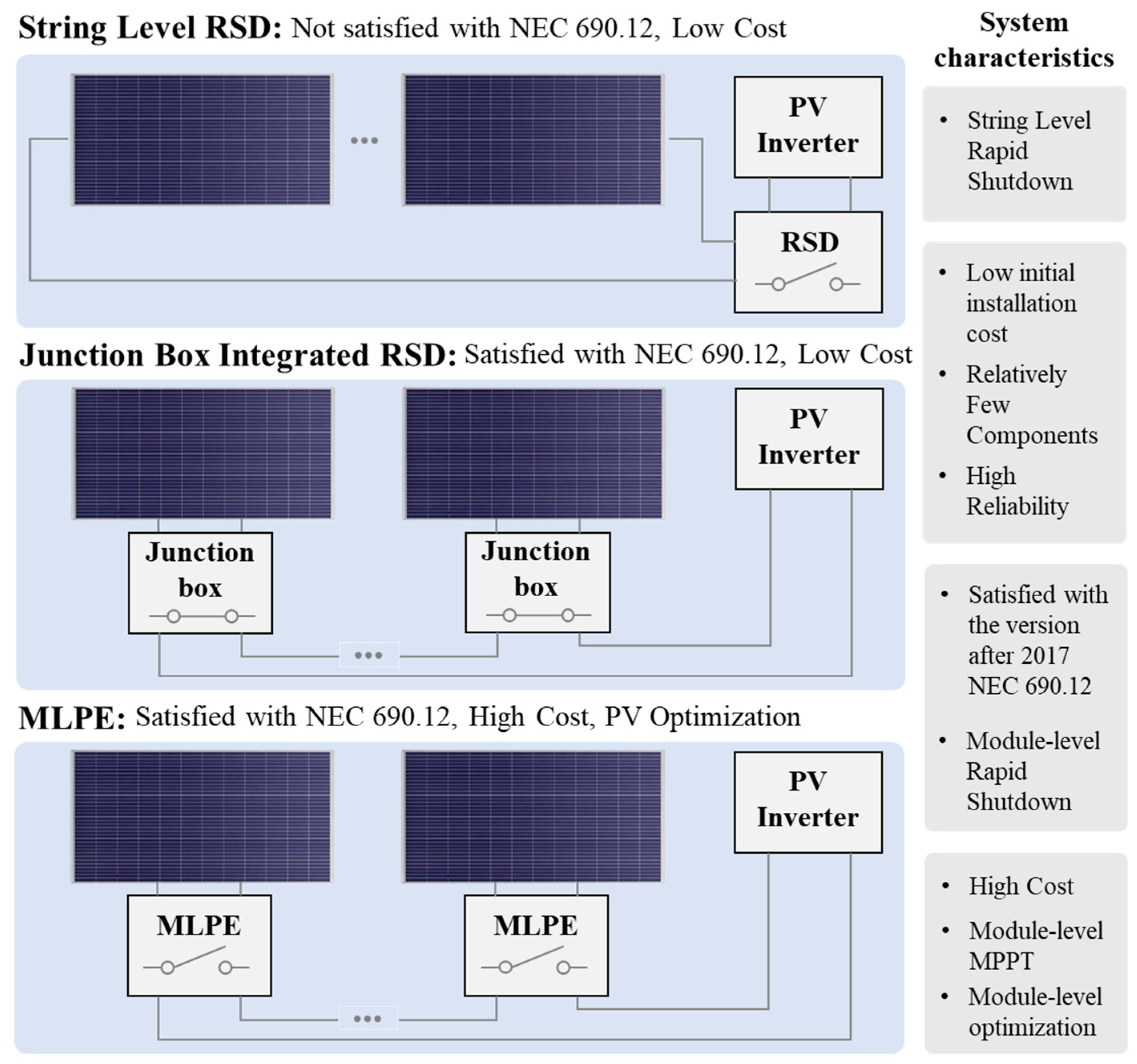
2.1. System Component and Principle

The proposed system integrates into the junction box of each photovoltaic module to create a short circuit within the module upon receiving a PWM signal, thereby driving the module’s voltage to converge to zero. Each junction box contains one power semiconductor and one controller responsible for performing the rapid shutdown function.
The junction-box–integrated rapid shutdown system is divided into four main components. First, the signal input and filter part receive the rapid shutdown signal, composed of PWM, and filter it to determine whether the signal has been received. Second, the rectifier and optocoupler part transmits the signal to the power semiconductors installed in each module, which have different ground potentials. Third, the gate driver and power part drive the gates upon receiving the signal. Finally, the system consists of power semiconductors that perform the rapid shutdown function by creating a short circuit within the module. The overall structure is illustrated in Figure 1.
When the junction box performs rapid shutdown, the power semiconductor creates a short-circuit condition within the photovoltaic module, which results in a short-circuit current flowing inside the module. In this case, the I-V curve of the photovoltaic module converges to 0 voltage when the short-circuit current is flowing, as shown in Equation (1). The power loss in the power semiconductor can be calculated as expressed in Equation (2). While, in general, power electronic systems consider both conduction loss and switching loss in the design process, this system only considers conduction loss. Figure 2. shows the voltage–current (I-V) curve during the rapid shutdown process.
P = V S C I S C 0
P M O S F E T = I S C 2 R d s o n ,   P T h y r i s t o r = V T I S C

2.2. Design Consideration

In a junction-box–integrated rapid shutdown system, the power semiconductors (MOSFETs, Thyristors) responsible for rapid shutdown are integrated into each photovoltaic module, resulting in separate ground potentials. A common method to drive these semiconductors is to use an isolated converter, but this increases costs. Therefore, to receive signals transmitted from the common ground outside the system and drive power semiconductors with different photovoltaic module grounds, we propose a gate drive circuit that utilizes signal isolation via an optocoupler and the photovoltaic module’s generated voltage. Using a structure like the Gate Driver and Power circuit in Figure 1, energy required for driving the power semiconductor can be stored using a simple voltage divider circuit, blocking diode, and capacitor. The voltage stored in C1 is given by Equation (3), and the stored energy is expressed as Equation (4).
V C 1 = V P V M A X R 2 R 1 + R 2 V D 1
E C 1 = 1 2 C 1 V C 1 2

2.3. Communication System and Wiring Configuration

In conventional MLPE systems, Power Line Communication (PLC) is used to receive rapid shutdown signals and sense module voltage [21,22]. Implementing PLC requires a coupling circuit, a modulator, a demodulator, and a high-performance MCU. However, this communication method deviates from the concept of a junction-box–integrated rapid shutdown system, which aims to enhance cost competitiveness and reliability by minimizing analog circuitry and reducing the number of components. Furthermore, employing high-level communication solely for receiving a simple rapid shutdown signal is not cost-effective.
To address this issue, we implemented the SAE J1772 PWM communication method, which has been widely adopted and proven reliable in various applications. This method transmits a 1 kHz PWM signal along a daisy-chained control line, similar to its application in EV–EVSE systems. Each module receives the signal via a band-pass filter and uses an optocoupler for isolation and command interpretation. The absence of the PWM signal triggers a default shutdown, enabling a fail-safe operation with minimal additional hardware [23]. Owing to its simple implementation, low maintenance requirements, and high stability, this method is particularly well-suited for unidirectional data transmission. To integrate this approach into each module, a daisy-chain wiring scheme, commonly employed in Battery Management Systems (BMS), was adopted. This configuration simplifies wiring, enhances scalability, and offers a cost-effective solution. Table 4 summarizes the system-level specifications for the PWM-based rapid shutdown communication method.
For rapid shutdown operation, when an external PWM generator transmits a shutdown signal, each module connected in a daisy-chain configuration receives the signal through a band-pass filter. Subsequently, an optocoupler isolates the signal and drives the power semiconductor, triggering the rapid shutdown. Figure 3. illustrates the communication methods utilized in both the MLPE system and the junction-box–integrated rapid shutdown system.

3. Simulation and Experimental Results

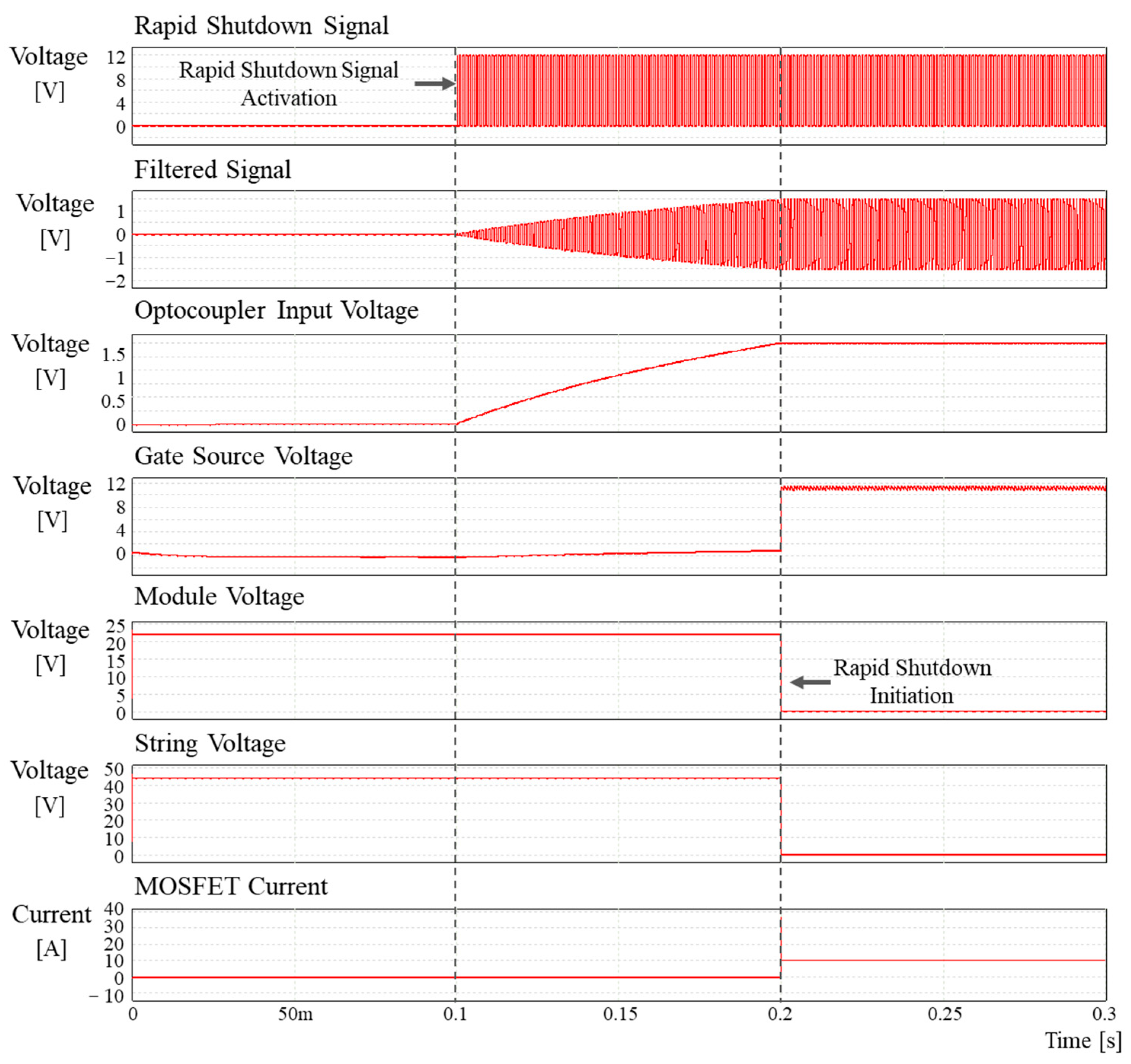
3.1. Simulation Result

To validate the feasibility of the proposed system, simulations were conducted using PSIM Professional 2021 a.2.5. The simulation incorporated a three-state modeled MOSFET, with the parameters summarized in Table 5 and the simulation platform illustrated in Figure 4. To reduce computational complexity, the simulation assumed a string configuration consisting of two modules connected in series. The results demonstrate that, upon applying the rapid shutdown signal, the module voltage decreases to below 0.2 V within approximately 100 ms.

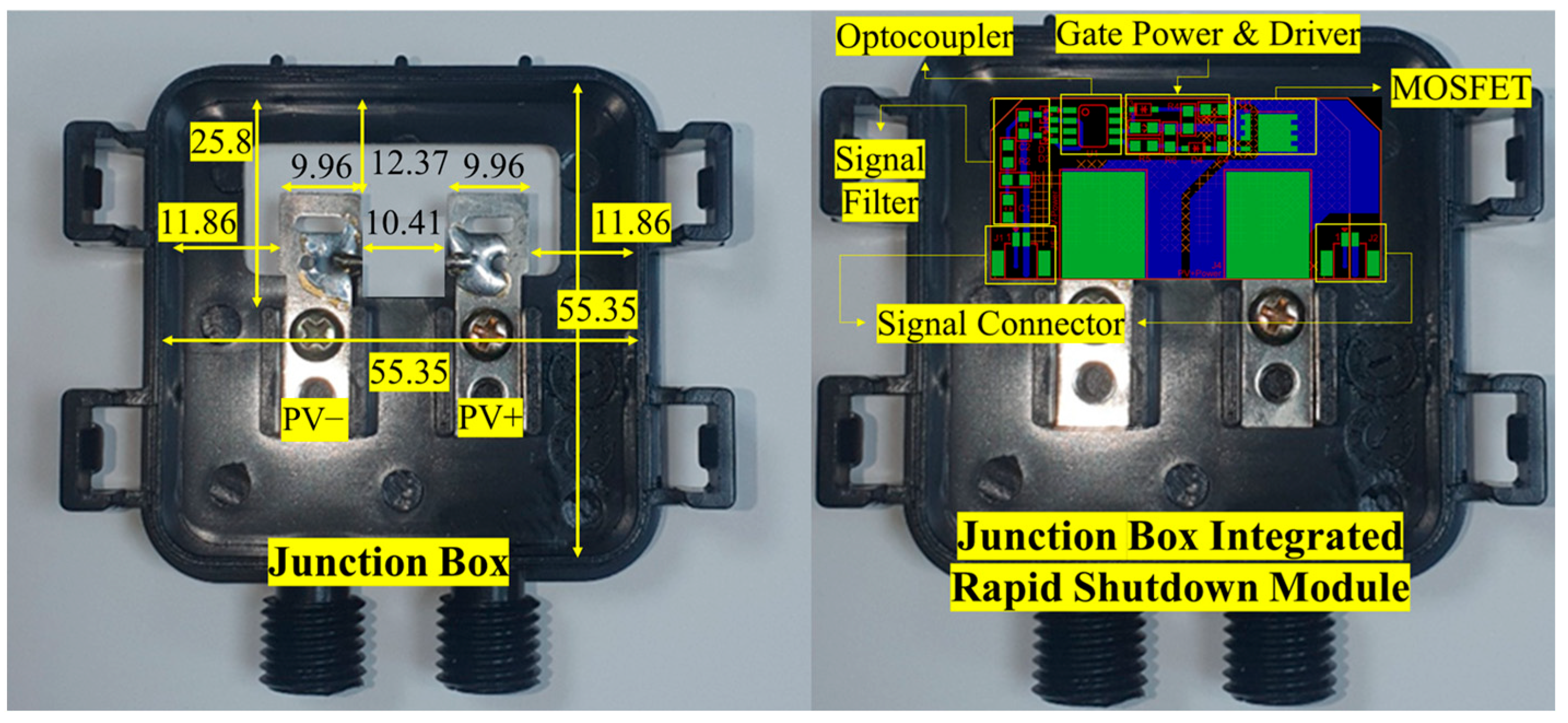
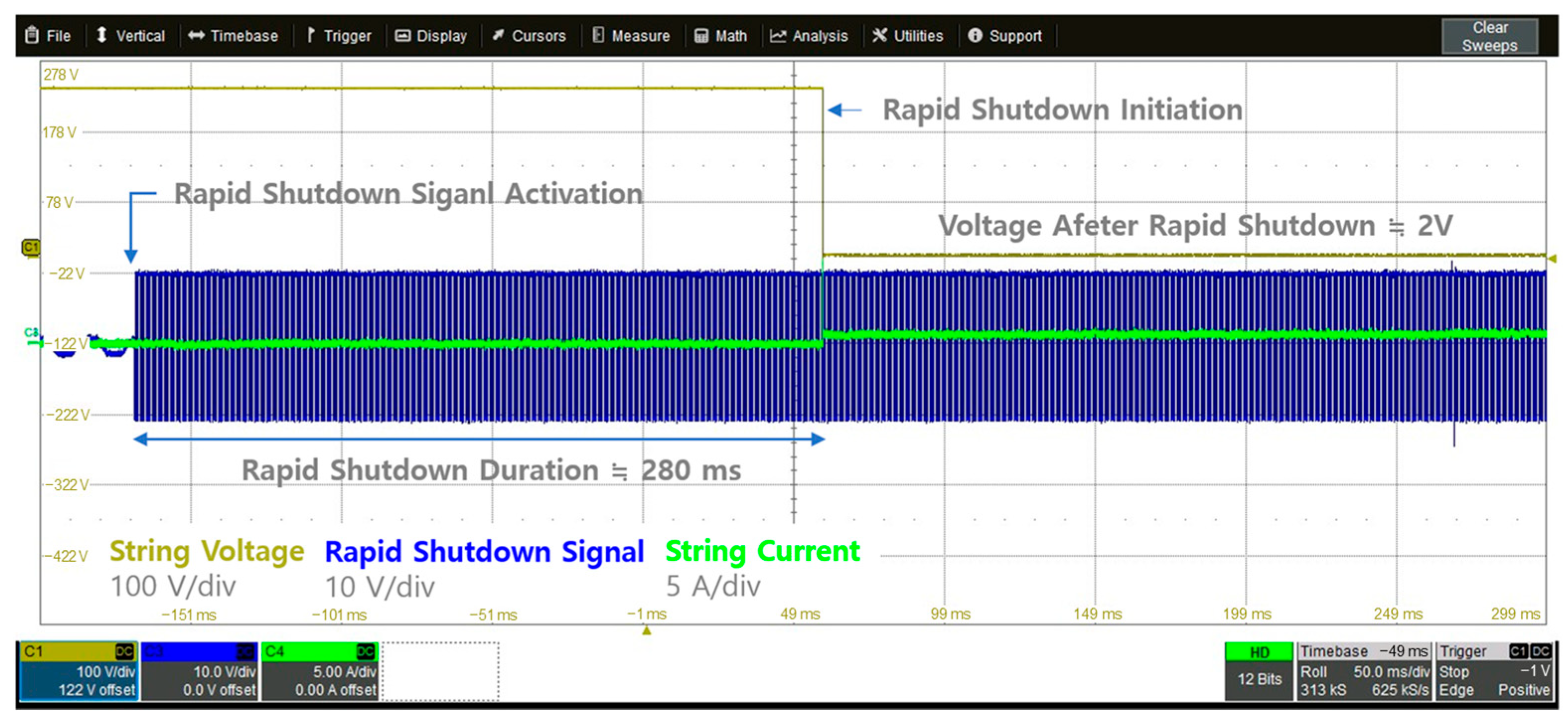
3.2. Experimental Result

The junction box–integrated rapid shutdown module is designed to be directly integrated with the output terminals of the junction box. The controller is incorporated into the output terminals of the photovoltaic module, and each rapid shutdown module is equipped with two signal connectors to facilitate a daisy-chain wiring configuration. The dimensions of the implemented junction box and the structure of the mounted PCB are presented in Figure 5. The assembly method of the photovoltaic module and the rapid shutdown module is shown in Figure 6 and the before and after of the rapid shutdown modules are shown in Figure 7. In addition, Table 6 presents the key specifications of the main components (MOSFET and optocoupler) for the practical implementation of the junction-box–integrated rapid shutdown system.
System integration testing was conducted using BIPV modules. These modules are designed with colored cells for the application of BIPV systems and are implemented in a form that integrates or attaches to the roof or walls of buildings. Figure 8 illustrates the building integrated photovoltaic module used for system integration testing. Experimental results show that, following the reception of the rapid shutdown signal, the voltage of each module and the string voltage drop below 2 V within 280 ms, as shown in Figure 9.

4. Discussion

Commercially available rapid shutdown solutions can be broadly classified into two categories: string-level rapid shutdown systems used prior to NEC 2017 [5], and MLPE systems, which enable shutdown at the individual module level. While string-level systems do not meet current NEC requirements and therefore cannot be used in regions where the NEC applies, they remain a viable alternative elsewhere and offer relatively lower upfront costs compared to MLPE. By contrast, MLPE systems comply with NEC regulations and can mitigate power losses under partial shading conditions. However, because each module requires its own power conversion device, the initial installation cost is higher.
In this paper, we propose a junction-box–integrated rapid shutdown system that satisfies NEC requirements and is particularly well suited to environments without partial shading. The system relies on analog circuitry that operates only when a rapid shutdown signal is triggered, resulting in lower installation costs and higher reliability compared to MLPE. Accordingly, this junction-box–integrated solution can be considered a promising alternative to promote the adoption of BIPV, depending on the deployment context.
As illustrated in Figure 10, commercially available rapid shutdown solutions can be categorized into string-level systems, MLPE-based systems, and the proposed junction-box–integrated system. In addition, Table 7 summarizes and compares the key components of these three types of rapid shutdown systems.
Compared to existing MLPE-based solutions, the proposed junction-box–integrated system offers significant advantages in terms of reduced installation cost, simplified architecture, and enhanced reliability by minimizing component count. However, it may not provide localized maximum power point tracking (MPPT) capabilities under partial shading conditions, unlike MLPE systems.

5. Conclusions

This paper proposes a junction-box–integrated rapid shutdown system for BIPV environments that satisfies NEC 690.12 requirements while aiming to balance low installation cost and high reliability. By designing the system around analog circuitry that operates only upon receiving a rapid shutdown signal, it is possible to significantly reduce the number of components compared to conventional MLPE-based solutions.
Through simulations PSIM and laboratory experiments, we verified that the proposed system can lower module and string voltages to 2 V or less within approximately 280 ms, an outcome crucial for ensuring PV system safety. Additionally, the reduction in components may lead to lower initial capital costs and potentially improved MTBF, although further validation, in particular long-term field testing and large-scale deployments, is warranted. Notably, in BIPV scenarios with minimal partial shading, MLPE’s added performance benefits tend to be limited, suggesting that this junction-box–integrated rapid shutdown system could serve as a promising alternative in such contexts.
Future work should address signal interference and communication stability under large-scale conditions, as well as evaluate the system’s performance under partial shading scenarios. In addition, it may be worth exploring a simplified integration of certain MLPE functionalities, such as module-level monitoring. Such efforts could further enhance both the economic feasibility and reliability of BIPV systems, thereby contributing to broader solar market adoption.

Author Contributions

Conceptualization, J.-Y.J.; Methodology, Y.-D.L. and Y.-H.K.; Validation, J.-Y.J., M.K., M.S. and J.-H.K.; Writing—original draft, J.-Y.J.; Writing—review & editing, Y.-D.L. and Y.-H.K. All authors have read and agreed to the published version of the manuscript.

Funding

This work was supported by the Korea Institute of Energy Technology Evaluation and Planning (KETEP) and the Ministry of Trade, Industry & Energy (MOTIE) of the Republic of Korea (RS-2021-KP002576, RS-2024-00398351 & RS-2024-00459594).

Data Availability Statement

The original contributions presented in this study are included in the article. Further inquiries can be directed to the corresponding authors.

Conflicts of Interest

The authors declare no conflict of interest.

References

  1. Breyer, C.; Khalili, S.; Bogdanov, D.; Ram, M.; Oyewo, A.S.; Aghahosseini, A.; Gulagi, A.; Solomon, A.A.; Keiner, D.; Lopez, G.; et al. On the History and Future of 100% Renewable Energy Systems Research. IEEE Access 2022, 10, 78176–78218. [Google Scholar] [CrossRef]
  2. Wu, Z.; Hu, Y.; Wen, J.X.; Zhou, F.; Ye, X. A Review for Solar Panel Fire Accident Prevention in Large-Scale PV Applications. IEEE Access 2020, 8, 132466–132480. [Google Scholar] [CrossRef]
  3. Yang, R.; Zang, Y.; Yang, J.; Wakefield, R.; Nguyen, K.; Shi, L.; Trigunarsyah, B.; Parolini, F.; Bonomo, P.; Frontini, F.; et al. Fire safety requirements for building integrated photovoltaics (BIPV): A cross-country comparison. Renew. Sustain. Energy Rev. 2023, 173, 113112. [Google Scholar] [CrossRef]
  4. National Fire Protection Association. National Electrical Code (NEC) 2014, Article 690.12, Rapid Shutdown of PV Systems on Buildings; NFPA: Quincy, MA, USA, 2014. [Google Scholar]
  5. National Fire Protection Association. National Electrical Code (NEC) 2017, Article 690.12, Rapid Shutdown of PV Systems on Buildings; NFPA: Quincy, MA, USA, 2017. [Google Scholar]
  6. National Fire Protection Association. National Electrical Code (NEC) 2020, Article 690.12, Rapid Shutdown of PV Systems on Buildings; NFPA: Quincy, MA, USA, 2020. [Google Scholar]
  7. National Fire Protection Association. National Electrical Code (NEC) 2023, Article 690.12, Rapid Shutdown of PV Systems on Buildings; NFPA: Quincy, MA, USA, 2023. [Google Scholar]
  8. Lima, J.P.C.; da Cunha Lima, A.; Bellinaso, L.V.; Michels, L. Explanatory Review about Rapid Shutdown Systems and Standards to Increase Safety in Photovoltaic Systems. In Proceedings of the 2022 14th Seminar on Power Electronics and Control (SEPOC), Santa Maria, Brazil, 12–15 November 2022; pp. 1–5. [Google Scholar] [CrossRef]
  9. Zetawi, E.A.; Abdulhadi, E.O.; Shahroury, F.R.; Ahmad, H.H.; Akour, A. Components and Specification of Rapid Shutdown for Roof PV Systems. In Proceedings of the 2021 International Conference on Microelectronics (ICM), New Cairo City, Egypt, 19–22 December 2021; pp. 182–185. [Google Scholar] [CrossRef]
  10. One Batterymarch Park. Fire Fighter Safety and Emergency Response for Solar Power Systems; One Batterymarch Park: Quincy, MA, USA, 2010. [Google Scholar]
  11. Kabalcı, E. Review on novel single-phase grid-connected solar inverters: Circuits and control methods. Sol. Energy 2020, 198, 247–274. [Google Scholar] [CrossRef]
  12. Sajid, S.; Javed, M.Y.; Jaffery, M.H.; Ashraf, M.S.; Naveed, M.T.; Hafeez, M.A. Modular level power electronics (MLPE) based distributed PV system for partial shaded conditions. Energies 2022, 15, 4797. [Google Scholar] [CrossRef]
  13. Parker, T.P.; Chapman, P.L.; Gilchrist, P. Dominant factors affecting reliability of alternating current photovoltaic modules. In Proceedings of the 2015 IEEE 42nd Photovoltaic Specialist Conference (PVSC), New Orleans, LA, USA, 14–19 June 2015; pp. 1–6. [Google Scholar] [CrossRef]
  14. Flicker, J.; Tamizhmani, G.; Moorthy, M.K.; Thiagarajan, R.; Ayyanar, R. Accelerated Testing of Module-Level Power Electronics for Long-Term Reliability. IEEE J. Photovolt. 2017, 7, 259–267. [Google Scholar] [CrossRef]
  15. IEC 60364-7-712; Electrical Installations of Buildings—Part 7-712: Requirements for Special Installations or Locations–Solar Photovoltaic (PV) Power Supply Systems. International Electrotechnical Commission: Geneva, Switzerland, 2017.
  16. AS/NZS 5033; Installation and Safety Requirements for Photovoltaic (PV) Arrays. Standards Australia: Sydney, Australia, 2014.
  17. CSA C22.1:21; Canadian Electrical Code (CEC), Part I: Safety Standard for Electrical Installations. Canadian Standards Association: Mississauga, ON, Canada, 2018.
  18. VDE-AR-E 2100-712; Requirements for the Installation of Photovoltaic Systems. VDE Association for Electrical, Electronic & Information Technologies: Frankfurt, Germany, 2019.
  19. JIS C 8955; Photovoltaic Power Generation Systems. Japanese Standards Association: Tokyo, Japan, 2017.
  20. BS 7671; IET Wiring Regulations. British Standards Institution: London, UK, 2020.
  21. Ricardo, A.; Pereda, A.; Bilbao, E.; Cortajarena, J.A.; Vidaurrazaga, I.; Román, E. Design and analysis of performance of a DC power optimizer for HCPV systems within CPVMatch project. In Proceedings of the AIP Conference Proceedings, Puertollano, Spain, 16–18 April 2018; AIP Publishing: Melville, NY, USA, 2018; Volume 2012. [Google Scholar]
  22. Evans, D.; Cox, R. Powerline communications strategy enabling fully decentralized control of AC-stacked PV inverters. In Proceedings of the 2017 IEEE Energy Conversion Congress and Exposition (ECCE), Cincinnati, OH, USA, 1–5 October 2017; pp. 2277–2284. [Google Scholar] [CrossRef]
  23. SAE J1772; Electric Vehicle and Plug-In Hybrid Electric Vehicle Conductive Charge Coupler. Society of Automotive Engineers: Warrendale, PA, USA, 2017.
Figure 1. Proposed overall system configuration.
Energies 18 02983 g001
Figure 2. I-V curve during the rapid shutdown process.
Energies 18 02983 g002
Figure 3. Communication system and wiring configuration.
Energies 18 02983 g003
Figure 4. Verification with simulation platform.
Energies 18 02983 g004
Figure 5. Simulation result.
Energies 18 02983 g005
Figure 6. Dimensions of the implemented junction box and structure of the mounted PCB.
Energies 18 02983 g006
Figure 7. Assembly method of the rapid shutdown module.
Energies 18 02983 g007
Figure 8. Experimental setup of the proposed rapid shutdown system with BIPV modules.
Energies 18 02983 g008
Figure 9. Experimental results: transient characteristics of PV modules and string after rapid shutdown signal.
Energies 18 02983 g009
Figure 10. Comparison of 3-types rapid shutdown system architectures and components.
Energies 18 02983 g010
Table 1. Summary of key NEC 690.12 revisions.
NEC VersionKey Changes
2014Introduced the first rapid shutdown requirement, mandating power disconnection outside a 10 ft zone within 10 s.
Placing the inverter close to the array eliminated the need for “controlled conductors”; conductors beyond 10 ft required contactors/relays or disconnects [4].
2017Extended voltage reduction requirements to both inside and outside the array boundary.
Mandated ≤ 30 V outside and ≤80 V inside the array within 30 s of shutdown, emphasizing MLPE use [5].
2020Formally recognized firefighters as stakeholders.
Redefined the rapid shutdown device as a PV Hazard Control System
Required a single Rapid Shutdown Switch for the entire system [6].
2023Excluded certain structures (e.g., parking canopies, carports) where rooftop firefighter work is not involved.
PV system circuits terminating outside the building no longer classified as controlled conductors [7].
Table 2. Rapid shutdown requirement in NEC 690.12.
SectionContents
1. Overall RequirementThe PV system circuit must include rapid shutdown functionality to reduce the risk of electrical shock to emergency responders in case of an emergency.
2. Control Conductor RequirementsThe control conductors apply to circuits supplied by the PV system.
3. Control LimitsArray Boundary: The point 305 mm (1 ft) from the outermost part of the module and rack.
3.1. Outside the Array BoundaryControl conductors outside the array boundary or at the building entry point, more than 1 m (3 ft) away, must be reduced to 30 V or less within 30 s after rapid shutdown is initiated.
3.2. Inside the Array BoundaryMust meet one of the following:
(1)
The PV array must be certified as a rapid shutdown array or field labeled and installed as per instructions.
(2)
Control conductors within 1 m (3 ft) of the array or building penetration must be reduced to 80 V or less within 30 s after shutdown.
(3)
No exposed wiring or conductive parts within 2.5 m (8 ft) of the PV array, in which case the 690.12(B)(2) compliance is not required.
4. Additional DefinitionsThe array boundary is the 305 mm (1 ft) boundary line from the PV module and rack edges. If multiple arrays are less than 2 ft apart, they are considered as a single continuous array.
Table 3. Rapid shutdown requirements: a comparison of major countries.
CountryStandardRequirements
USANEC 690.12Voltage must be reduced to a safe level within 30 s in the array [4,5,6,7].
EuropeIEC
60364-7-712
No direct requirements but provides safety guidelines [15].
Australia
/New Zealand
AS/NZS 5033Requires DC and AC disconnect switches, introduces module level rapid shutdown [16].
CanadaCECVoltage must be reduced to a safe level within 30 s in the array [17].
GermanyVDE-AR-E 2100-712Requires module level rapid voltage shutdown, considering fire safety [18].
JapanJIS C 8955Rapid voltage shutdown requirements are less defined, for emergency response [19].
UKBS 7671No clear requirements for rapid voltage shutdown [20].
Table 4. System-level specifications for PWM-based rapid shutdown communication.
ParameterSpecificationRemarks
PWM Frequency1 kHzFixed frequency
Duty Cycle for Shutdown Command50%Shutdown trigger signal
Signal Transmission MethodDaisy-chain wiringSimilar to BMS topology
Signal Reception FilterBand-pass filter tuned at 1 kHzAdopted from EV-EVSE standard
Control Line Voltage12 V ± 5%PWM signal voltage level
Table 5. Simulation parameter.
ComponentParameterValueUnit
PV Module V O C 22.92V
I S C 10.57A
MOSFET R D S ( O N ) 20
V t h 2V
C g s 1195pF
C g d 31pF
C d s 506pF
OptocouplerCurrent Transfer Ration8-
V f 1.5V
Table 6. Key specifications of main components used in the junction-box–integrated rapid shutdown system.
ComponentParameterValue
Unit
Si MOSFET V D S
Drain-Source Breakdown Voltage
60 V
I D
Continuous Drain Current
90 A
R D S ( O N )
On-Drain-Source Resistance
4.8 mΩ
V G S
Gate-Source Voltage
−20 V, +20 V
C i s s
Input Capacitance
6300 pF
C o s s
Output Capacitance
1100 pF
C r s s
Reverse Transfer Capacitance
47 pF
OptocouplerCurrent Transfer Ration100%
V F
Input Forward Voltage
1.15 V
Isolation Surge Voltage2500 Vac (rms)
V C E O
Collector-Emitter Breakdown Voltage
30 V
I C
Collector Current-Continuous
150 mA
Table 7. Comparative analysis of core components in 3-types rapid shutdown systems.
ComponentMLPEJunction-Box–
Integrated Rapid Shutdown System
String RSD
Power Inductorw/w/ow/o
Input Capacitorw/w/ow/o
Output Capacitorw/w/ow/o
PLC Modulew/w/ow/o
MCUw/w/ow/o
Power Semiconductorw/
(2 or 4 [ea])
w/o
(1 [ea])
w/o
Auxiliary Powerw/w/ow/o
Optocouplerw/ow/w/o
Circuit Breakerw/ow/ow/
Control Power Supplyw/ow/ow/
Discharge Circuitw/o w/ow/
“w/” indicates that the component is essential and included by design in the corresponding rapid shutdown system. “w/o” means that the component is not required and thus not included in the system’s architecture.
Disclaimer/Publisher’s Note: The statements, opinions and data contained in all publications are solely those of the individual author(s) and contributor(s) and not of MDPI and/or the editor(s). MDPI and/or the editor(s) disclaim responsibility for any injury to people or property resulting from any ideas, methods, instructions or products referred to in the content.

