Article

Optimal Reactive Power Dispatch Planning Considering Voltage Deviation Minimization in Power Systems

1
Master’s Program in Electricity, Salesian Polytechnic University, Quito EC170702, Ecuador
2
Smart Grid Research Group—GIREI (Spanish Acronym), Electrical Engineering Department, Salesian Polytechnic University, Quito EC170702, Ecuador
*
Author to whom correspondence should be addressed.
Energies 2025, 18(11), 2982; https://doi.org/10.3390/en18112982
Submission received: 5 May 2025 / Revised: 2 June 2025 / Accepted: 3 June 2025 / Published: 5 June 2025
(This article belongs to the Special Issue Simulation and Analysis of Electrical Power Systems)

Abstract

:
Transmission lines in electrical power systems are studied and analyzed to improve the electrical system’s safety, stability, and optimal operation. Past research has proposed various optimization methods to address the problem of active and reactive power; however, they do not consider the voltage at the nodes, which causes losses in the system. By proposing a reduction in voltage at the nodes of the electrical system, it is possible to minimize voltage variation in the system using mixed integer nonlinear programming. The proposed methodology was tested on the IEEE 30-bus test system, where the objective function was modeled and simulated independently to test the results achieved through an AC OPF and reducing energy loss in the system. One of the most important investments was to demonstrate that the proposed methodology reduces voltage deviation at the system nodes, effectively confirming and maintaining lower active and reactive power production losses, resulting in a new type of energy planning that effectively benefits the electrical system voltage.

1. Introduction

The planning of electrical systems is highly complex. It not only involves balancing the power generated with the system demand but also considers technical losses in transmission lines, minimizes operating costs, and maximizes reliability and stability, among other operating conditions that may arise due to the stochastic characteristics of some of the variables. Thus, optimal reactive power dispatch (ORPD) has become an alternative for generation dispatch and reactive control in power systems [1].
The operation of an electrical power system (EPS) consists of three main parts, the first of which is the production of electricity from various energy sources (kinetic energy, potential energy, thermal energy, etc.). Another part of the regular operation of an EPS is the power transmission system, which includes components such as transmission substations, compensation systems, and transmission lines that efficiently transfer power from one point to another. The third component involves distributing and marketing energy to end consumers to meet user needs. In summary, the transmission system’s key is transporting the required energy without interrupting the end user. Due to growing demand and competition in the electricity market, electrical systems are often forced to operate close to safety limits. Therefore, voltage instability is one of the most pressing problems for electrical system operators [2].
This is due to the increasing consumption of active power in the electrical system with non-linear loads, and, therefore, the consumption of inductive reactive power causes voltage fluctuations in the system due to its time-varying characteristic. Reactive power causes energy losses and inefficient voltage distribution, which causes the system to decrease service quality. In most cases, when faced with a fault on a power line or power plant, other substations in the electrical system provide power to the affected area, provided that there is network redundancy. This causes additional power losses on the transmission lines and voltage losses at the system nodes. Reactive power compensation on the load side can improve busbar voltage quality, but traditional compensation methods lack the necessary flexibility [3]. Solving the reactive power dispatch dilemma in power systems is important for reducing energy losses and improving voltage distribution. The basic power system operation planning task is the optimal distribution of reactive power [4].

1.1. Literature Review

This section presents the most relevant works in the state-of-the-art review that have analyzed the reactive power dispatch problem in power systems.
Previous studies have proposed a method combining artificial rabbit optimization (ARO) and gradient optimization (GO) algorithms to solve the ORPD problem in an electrical network. To evaluate the effectiveness of this hybrid AROGBO technology, standarized IEEE-30, IEEE-57 bus, and IEEE-118 bus test systems were used, and two objective functions were tested for each system: minimum total power loss and minimum total voltage drop. The simulation results verify the accuracy and stability of the proposed ARO-GO method for solving the ORPD problem [5].
Due to growing demand and competition in the electricity market, electrical systems are often forced to operate close to safety limits. Therefore, voltage instability is one of the most pressing problems for electrical system operators. Different sensitivity models are applied to analyze voltage behavior problems with increasing reactive power loads in power systems. To this end, three different models were constructed to obtain linear voltage sensitivity using the full Jacobian matrix, the reduced Jacobian matrix, and the B” matrix of the fast decoupled current flow method. These three models can represent adequate approximations for large reactive powers [2].
In most cases, in the event of a power line or power plant failure, other substations in the electrical system provide the load to the damaged area. This causes additional energy losses in the transmission lines and voltage losses at the system nodes. Reactive power compensation on the load side can improve voltage quality at the busbars, but traditional compensation methods lack the necessary flexibility. To this end, the use of two types of FACTS devices (STATCOM (Synchronous Static Compensator) and Thyristor-Controlled Reactor with Fixed Capacitors (FCTCR)) is proposed to improve voltage distribution in high-voltage networks under abnormal operating conditions, such as sudden heavy loads. Power flow calculations are performed to identify critical busbars. Then, the performance of FACTS devices under heavy load is investigated when the devices are individually connected to the critical busbars. The busbar voltage drop is 1.5%, which decreases to 0.78% with STATCOM and to 0.96% with FCTCR [3].
Solving the reactive power dispatcher dilemma in electrical systems is essential for reducing energy losses and improving voltage distribution. The basic power system operation planning task is the optimal reactive power distribution. The particle swarm optimization method is proposed to achieve optimal reactive power planning. The effectiveness of this approach is demonstrated by its high processing speed and the results obtained from a comprehensive global search for reactive power planning. Furthermore, experimental results confirmed the algorithm’s effectiveness in optimizing the objective function through several studies [4].
The optimal reactive power planning (ORPD) problem involves finding the optimal configuration of reactive power resources in a network, often to minimize active power losses. The ORPD problem is modeled as a mixed-integer nonlinear programming problem and solved using two different metaheuristic methods, mean variance mapping optimization and the genetic algorithm. The novelty is that the solution to the ORPD problem is implemented through the Python–DIgSILENT PowerFactory interface was implemented using Python 3.12 and DIgSILENT PowerFactory 2024 SP1, which combines the advantages of both software packages. Various tests were performed with IEEE test systems with 6, 14, and 39 buses. The results are compared with those previously reported in the literature, matching and in some cases improving the reported solutions with shorter computation times [6].
Inadequate voltage monitoring and control can cause the power system voltage to collapse, sometimes leading to massive power outages. Voltage management is performed in developing and industrialized countries by coordinating dispatch centers and transmission system operators. This can lead to a lack of coordination or faulty operations that can cause cascading events. Based on the problems involved in operator coordination, the design of an expert controller for power system voltage levels is presented. Using the pilot node concept allows the controller inventory to remain stable in the face of changes in network topology. The controller is validated by simulating instances from the library and comparing the resulting solutions with those provided by the optimal current flow and those obtained from the genetic algorithm. The basic result is uniform voltage curve processing and optimal reactive power routing without a two-step algorithm. The proposed controller is suitable for online and on-the-fly applications and is flexible to handle complex analytical formulation problems [7].
Recent advances in the ORPD problem, the mathematical formulation of the objective function, and a summary of various metaheuristic optimization techniques (simple and hybrid) have been used to solve the ORPD problem. Hybrid methods combine two or more methods to enhance one of their strengths and achieve a high-quality solution to the problem. Some existing methods do not guarantee the best solution, but combining devices such as renewable energy sources (RES) and FACTS will help achieve the best solution to the problem, allowing the power system to perform better, thus improving system reliability and voltage distribution. With all of the above, it can be concluded that hybrid technology provides a practical and high-quality solution to the ORPD problem [8].
PSO-DSO-DER (Particle Swarm Optimization, Distribution System Operation, and Distributed Energy Resources) systems use sensitivity analysis. In the three integration steps, the power curve of the unbalanced distribution system is first estimated. The transmission curve is modeled, and the reactive power required in emergencies is calculated. Finally, the desired reactive power sent to the transmission system operator (TSO) is calculated. The proposed interaction system was tested on a 37-node IEEE distribution line connected to a 9-bus IEEE transmission system. The simulation results show that sensitivity-aware planning can reduce the number of communication signals between distributed power sources and digital Earth observation stations and potentially reduce the risk of communication accidents [9].
The optimal reactive power distribution (ORPD) problem is one of the most critical problems facing the operation and control of power systems. ORPD is a nonlinear optimization problem that includes various control operations, such as generator reactive power output, transformer shunt control, and parallel compensation device control, and the voltage deviation is within a permissible range. The particle swarm optimization (PSO) method solves the ORPD problem by generating accurate solutions in a short calculation time [10].
By analyzing the transient voltage stability characteristics of the new high-power power grid and the main problems affecting voltage stability, a method is proposed for configuring the dynamic reactive power compensation device based on reactive power and voltage sensitivity to improve transient voltage stability. This method was used to determine the installation location of the reactive power compensation device. To achieve optimal control, the compensation device is determined by simulation as a synchronous capacitor and its rated power [11].
A reactive power coordination control strategy for new energy storage plants is presented. First, a multitemporal model for reactive power voltage control for new flexible energy and energy storage plants connected to hybrid AC-DC networks is developed. A simulation model was established in the time domain of the combined system and the energy storage plant, as well as a coordinated reactive power voltage control strategy at multiple time scales to connect the power plant and new flexible energy sources to the DC hybrid domain era. The simulation results show that this coordinated control strategy has good dynamic voltage and reactive power characteristics and voltage stability [12].
Actions to mitigate climate change generate significant changes and increase pressure on all sectors of the electricity system, from generation to distribution and consumers. Optimal Reactive Power Distribution (ORPD) reduces active power losses and improves bus voltage distribution in distribution networks. An improved sine-cosine algorithm (ImSCA) is proposed for ORPD distribution networks operating under different load scenarios. The case study compares the proposed ImSCA algorithms and the classic sine-cosine algorithm (SCA) and the impact of reactive power control on network operating conditions [13].
The effect of coordinated automatic voltage and reactive power control in an SEP containing wind turbines (WF) and SVCs is presented using an optimization representation in the form of optimal reactive power deviation (ORPD). The calculations were performed in IEEE 9 and IEEE 57-bus test scenarios. The results show that the longer the length of the EPS and the proportion of long-distance power lines, the greater the effect of voltage coordination control and voltage reactive power coordination control [14].
To consume renewable energy efficiently, a future planning method that considers flexible resources is proposed. Its characteristic is that, based on the relaxation of reactive power flow, energy storage (ES) losses are considered through the conicity constraint. Through case studies of advanced IEEE 33 nodes, it was found that active power and reactive power coordination can be taken into account when determining the operating conditions of the power supply network in the form of conical constraints. The operating voltage of the network is kept within the ideal range [15].
Correctly determining the control variables of the optimal reactive power dispatch (ORPD) problem is essential to ensure optimal power flow in power systems. Optimal control variables (continuous and discrete) are used in the advanced particle swarm optimization inertia weighting strategy (PSO). An improved inertia weighting strategy is proposed to avoid the local minimum trap and premature convergence of traditional TSOs. The proposed method has been investigated and validated on 14- and 30-bus IEEE systems. Comparative analysis of the results shows that this method effectively reduces active power losses by providing optimal control variables and can solve complex and high-dimensional problems [16].

1.2. Organization

Section 1—This presents the paper’s introduction and a review of the state of the art, showing the main research articles that have employed the ORDP problem.
Section 2—This section explains in detail the basis of the mathematical model used as the basis for the proposed ORPD-MNVD.
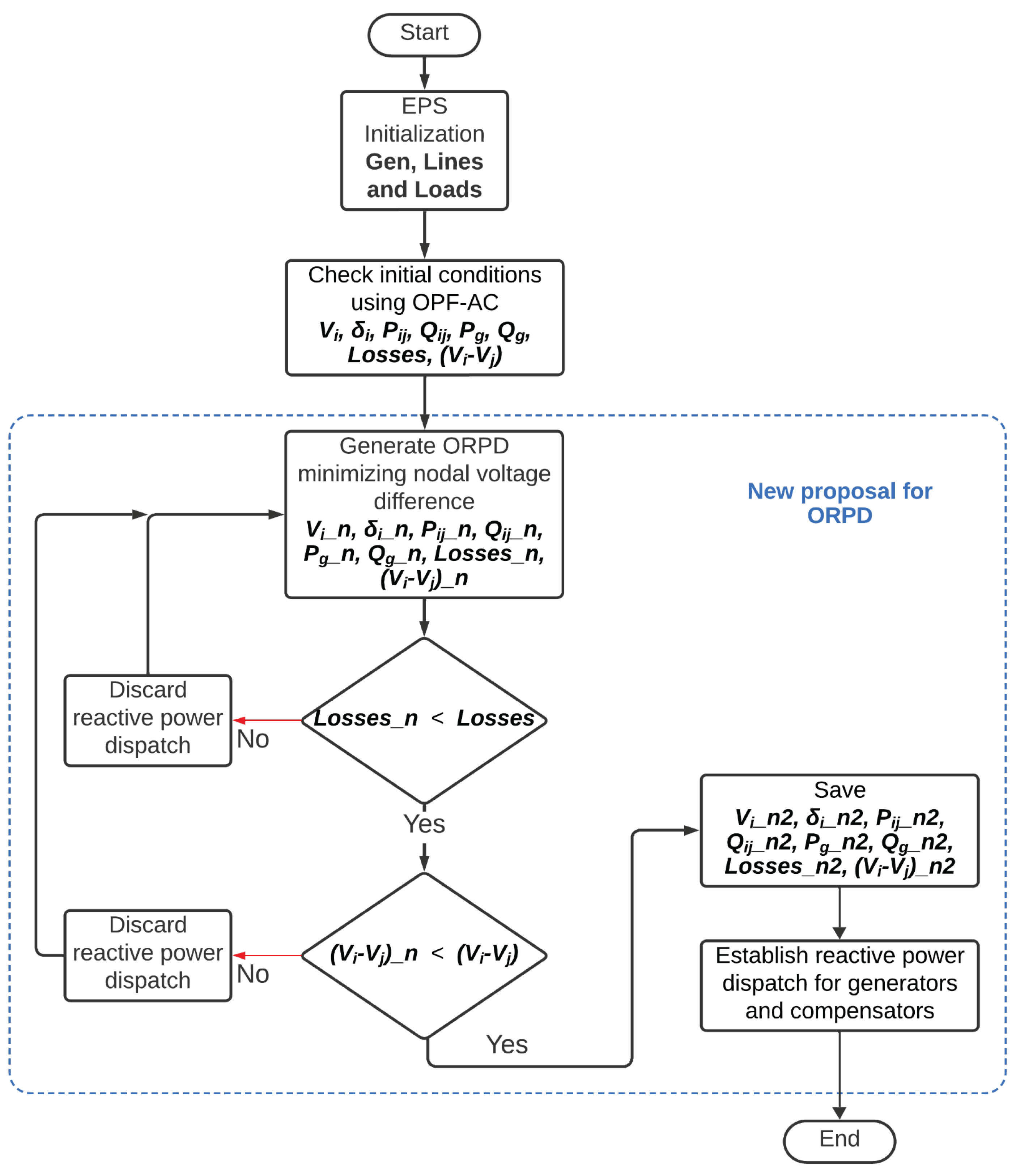
Section 3—This section explains the methodology formulation in a step-by-step process for the optimal reactive power dispatch with a novel objective function, and the different study cases considered.
Section 4—This section presents the application of this paper’s proposed methodology in three study cases, metrics, and statistical analysis.
Section 5—Conclusions: Presents a summary and overview of quantitative results obtained in the study cases; this section validates the effectiveness of the proposed index.

2. Reactive Power Dispatch

Optimal reactive power dispatch is proposed as an optimization problem that aims to minimize an objective function consisting of the total active power loss of the network [13]; others suggest reducing production costs, where the reduction is related to planning. The energy balance, active power, reactive power, and voltage reduction at the nodes limit the reactive power of generators.

2.1. Loss Minimization

The total power loss is determined from the active power balance equation, which is the difference between the real power supplied by the grid and the total active power required by the load, and is given by (1).
S i j = V i I i j *
This way, the active power flowing from node i to node j can be determined using (2), representing the apparent power. Similarly, the power flowing from node j to node i can be determined using (3).
P i j = V i 2 G i j V i V j G i j c o s ( δ i j ) V i V j B i j s i n ( δ i j )
P j i = V j 2 G i j V i V j G i j c o s ( δ i j ) + V i V j B i j s i n ( δ i j )
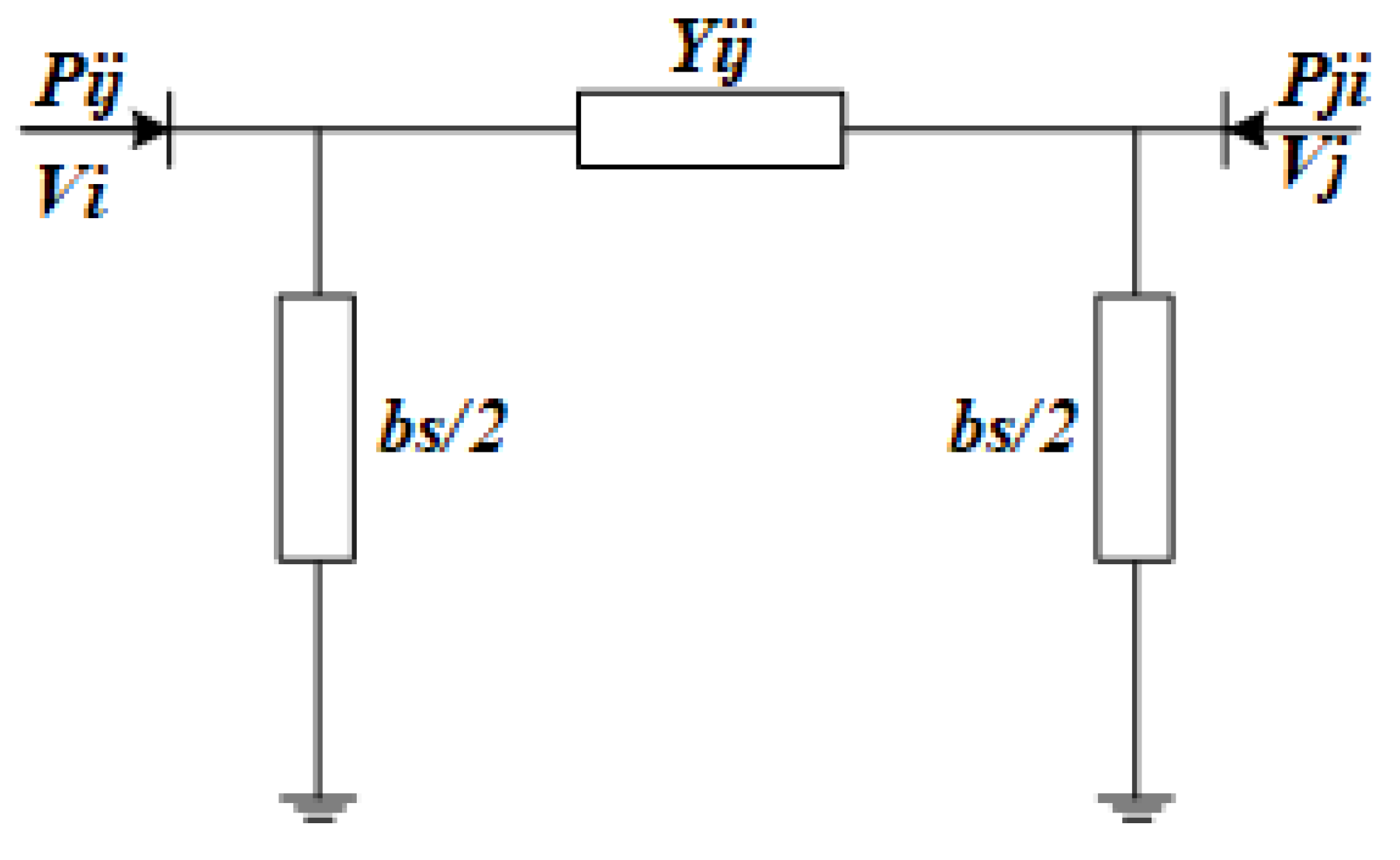
The proposed equations are derived from the π transmission line model shown in Figure 1.
By balancing the energy from node i, we obtain (4). The same equation helps us balance the energy from node j; by performing mathematical operations, we can obtain (5), representing the objective function we want to minimize for the entire SEP.
P l o s s i j = P i j + P j i
P l o s s i j = G i j V i 2 + V j 2 2 V i V j c o s ( δ i j )

2.2. Constraints

To find the optimal solution for reducing voltage deviations and costs, the limits of the equations corresponding to production and demand losses (5), active and reactive power (6) and (7), as well as the difference limitations corresponding to the systematizations within the limits of active and reactive power transmitted through the different generators (8) and (9), systematized within the corresponding limits of voltage amplitude (10) and angle (11), bifurcation compensation (12) and the load capacity of the transmission lines (13) are investigated. On the other hand, as shown in (14), the power of each generator will depend on the active and reactive power produced by each one.
P G i P D i = i = 1 N B V i 2 G i j + V i V j G i j c o s ( δ i j ) + B i j s i n ( δ i j )
Q G i Q D i = i = 1 N B V i 2 B i j V i V j G i j s i n ( δ i j ) B i j c o s ( δ i j )
P G i m i n P G i P G i m a x
Q G i m i n Q G i Q G i m a x
V i m i n V i V i m a x
δ i m i n δ i δ i m a x
Q c o m p i m i n Q c o m p i Q c o m p i m a x
S I L S i j S I L
S g = P G + j Q G

3. Methodology and Problem

The problem of optimal reactive power planning in ORPD is modeled as a mixed integer nonlinear programming problem based on optimal AC power flow. It is solved by considering various constraints and using node (i) and node (j) nodal analysis. It is based on minimizing the deviations of electrical parameters between nodes, adjusting voltage profiles through reactive power dispatch planning. To solve this problem, a new objective function is proposed, which is not considered in the scientific literature (15), which proposes the minimization of the nodal voltage deviation and evaluates the constraints of an AC OPF (6) to (14), to which (5) has been added as an additional constraint that allows the quantification of system losses. The proposed methodology is shown in Figure 2.
min Δ V = i = 1 N B j = 1 N B ( V i V j )

Study Cases

The proposed methodology was tested on the IEEE 30-bus test system, which consists of six generators connected to buses 1, 2, 5, 11, and 13. At the same time, it has 41 links, 34 referring to transmission lines, and the remaining 7 to transformers. In addition, two sets of parallel capacitors are connected to buses 10 and 24, providing characteristics of 0.3 p.u. Figure 3 shows the single-line diagram of the test system considered for this research. Table A1, Table A2 and Table A3 in Appendix A contain the EPS data.
In the first case, an OPF-AC analysis is performed, and active power dispatch is carried out. The results of this analysis are used as a starting point to verify the efficiency of the proposed methodology. In the second case, an ORPD minimizes EPS losses and represents an optimization challenge to regulate EPS operation. Its objective is to minimize power losses and ensure that generators operate within the specified limits. It focuses on improving the operation of the electrical system, ensuring that generators operate safely within their limits, and simplifying node voltage regulation, compensation device dispatch, transformer operation, and service quality at load nodes. It reduces energy losses and provides an adequate voltage profile at the system nodes, allowing generators to produce or consume reactive power according to their rated capacities. The results of the first and second cases are used for the third case, the suggested method, in which a new optimization is performed based on minimizing voltage variations at the system nodes. A new optimization is carried out to ensure that the voltage levels at the system nodes are optimal, improving voltage profiles and reconfiguring losses and power flow, introducing a new approach to planning reactive power dispatch with optimal voltage levels in the system, which reduces power losses and produces a more efficient and balanced system.

4. Analysis of Results

The single-objective optimization of the problem in optimal reactive power dispatch planning in electrical power systems, minimizing the nodal voltage deviation (ORPD-MNVD), was performed in GAMS software version 27.3.0 to verify the results obtained using a BIOSTAR Intel(R) Core (TM) i3-3240 @ CPU 3.40 GHz computer. The computer is 3.40 GHz with 12.00 GB of RAM and a Windows 10 64-bit operating system. The solver used for optimization was BONMIN in GAMS, which provided the solution to the NLP optimization problem.
The ORPD-MNVD was tested with the IEEE 30-bus test system. The first scenario analyzes the power flow under the conventional system to achieve the voltage at each bus. We then analyze the reduction in active power losses in the transmission lines to introduce an additional proposed method, which reduces the voltage deviation at the nodes. All of the above is performed using the traditional OPF-AC method.
Figure 4 models the voltage profiles, where it can be seen that, in each case, the values obtained in GAMS differ greatly and it is verified that the proposed method solves the problem of voltage loss at each node. Figure 4, for the OPF-AC case, illustrates a voltage with a magnitude of 1.1 p.u. on bus 11, which is the maximum limit defined in the voltage constraints, if there were a voltage increase on this bus. In turn, Figure 4, for the same case, also shows voltages below 1 p.u., with the most highlighted being the voltages of bars 19, 23, 24, 25, 26, 29, and 30 with values of 0.99, 0.99, 0.98, 0.99, 0.97, 0.98, and 0.96 p.u., proportionally. In the case where we minimized losses, the voltage profile for all bars increased compared to the OPF-AC case, with the most representative value in bar 13, which had a value of 1.09 p.u.
By minimizing power losses, their voltage profiles increase compared to the others, since active power losses are minimized and compensation elements not considered in the case of the OPF-AC are included, due to the very fact of compensation performed by the capacitor banks connected to busbars 10 and 24. Finally, by applying the proposed method, the voltage profiles decrease considerably and remain within range compared to the OPF-AC, and the minimization of losses in the system. According to the results analyzed in Figure 4, it can be observed that in case 1, by not improving or optimizing any technical variables or considering capacitor banks, the voltage profiles show very pronounced variations compared to the other cases, where technical parameters such as the reduction in active power losses are improved, as well as the inclusion of capacitor banks that help improve the SEP voltage profiles.
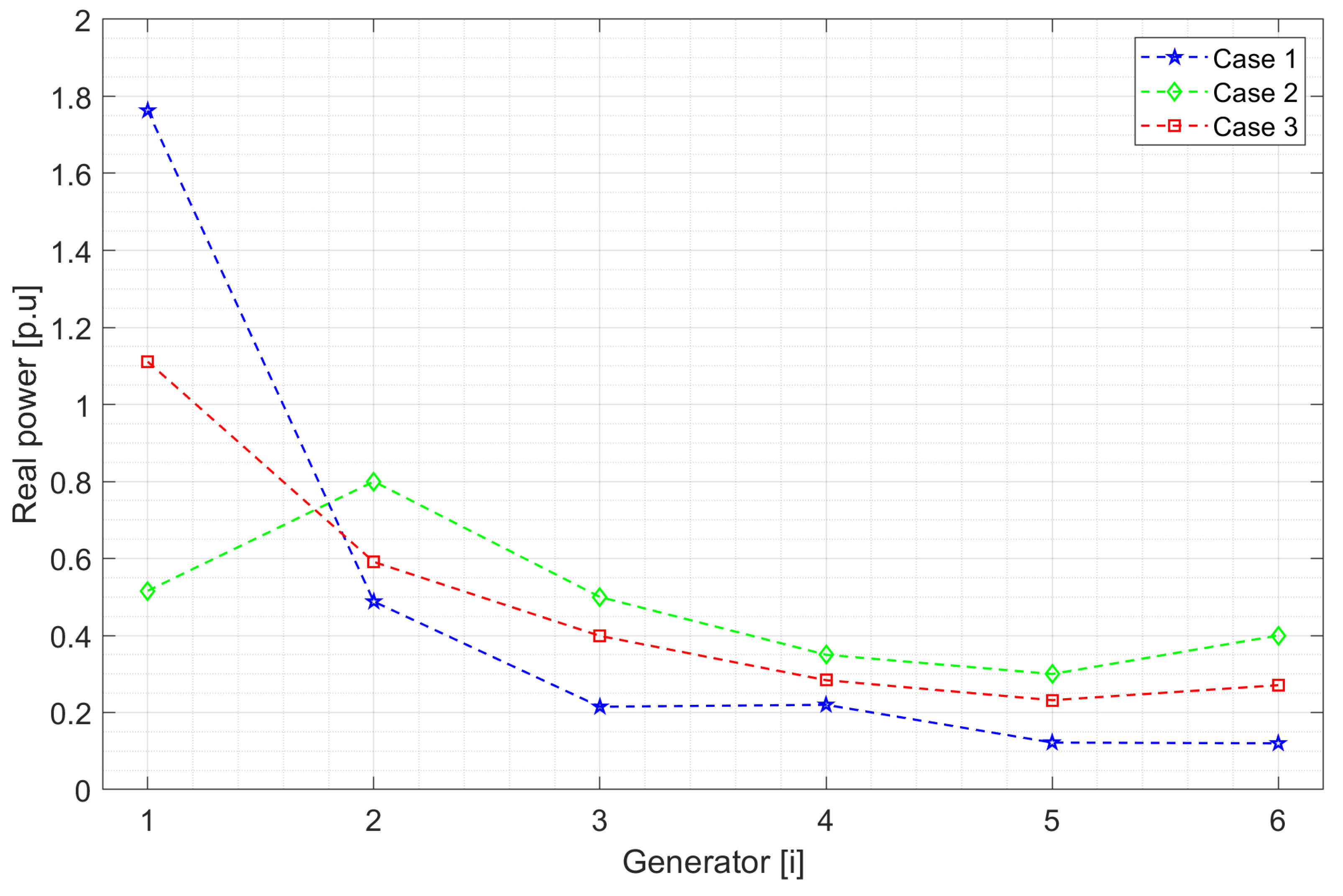
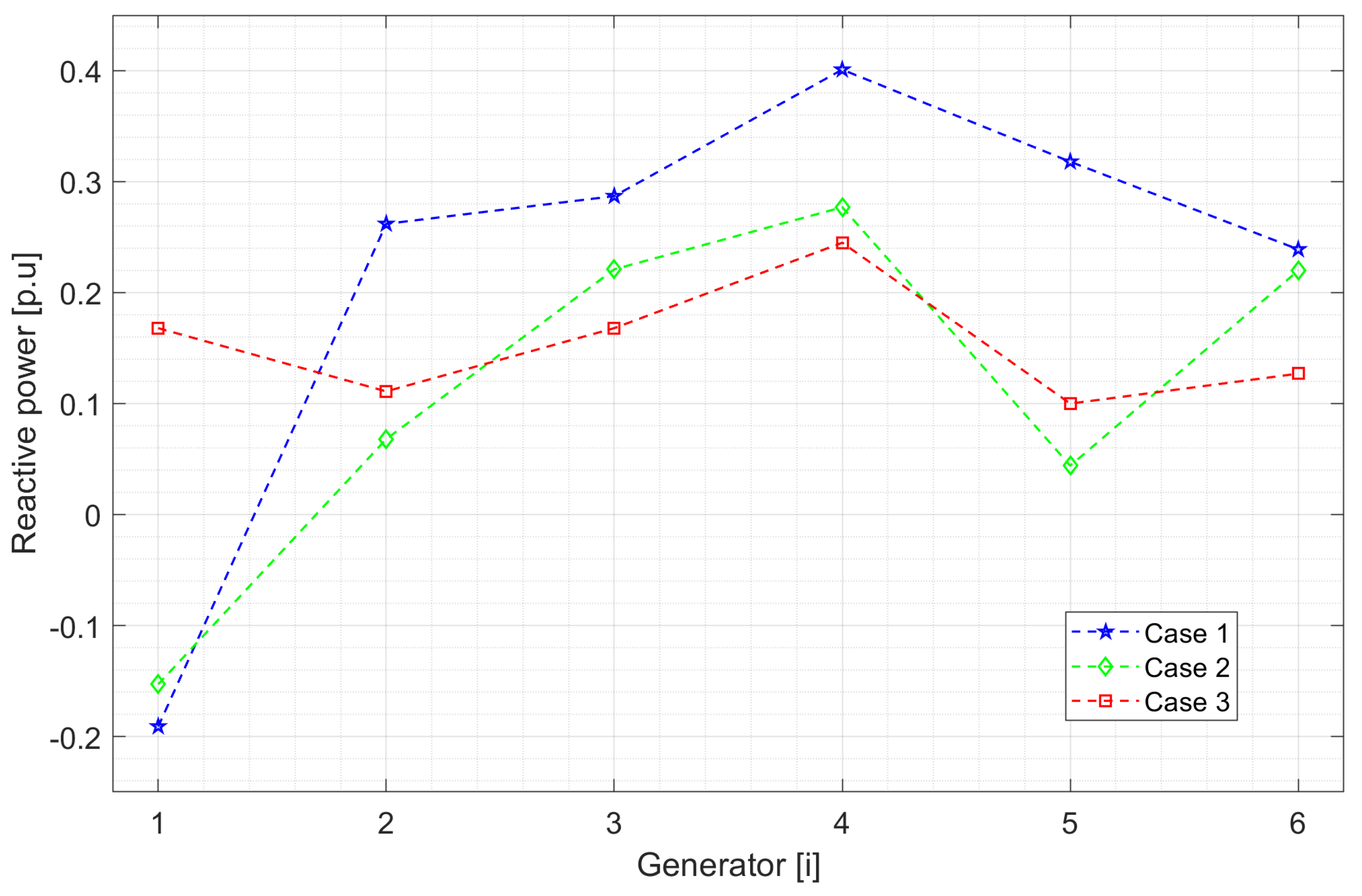
Table 1 shows the results of the active power dispatch of the generators, and Table 2 shows the reactive power of the generators and capacitive compensators located at nodes 10 and 24.
Analyzing the total power for case 3 in Table 2, the result obtained is much more favorable than in case 1, since there is a difference of 4.12 MW less than the power generated in case 1.
Figure 5 shows the active energy dispatches, presenting the same energy generation for cases 1 and 3, with generator 1 supplying more active power to the system. However, when losses are minimized in case 2, generator 2 provides the most active power. In case 3, generator 1 again provides the most energy; however, generation is lower than in cases 1 and 3, so the other generators generate more power, allowing us to balance losses.
When comparing the results obtained using the different methodologies, shown in Table 1 and Table 2, it can be seen that in case 3, which focuses on minimizing and deviating the voltage at the nodes in Table 1, 4 MW less active power is dispatched than AC-OPF, which is represented by case 1. However, in Table 2, the reactive power values in case 3 are different from those of the AC-OPF in case 1, by 4.12 MW.
Comparing the reactive power results of each generator in Figure 6 for cases 2 and 3, which consider capacitor banks, it was found that by minimizing active power losses in case 2, the reactive power generated is lower than in case 3, where losses are not minimized, indicating that reducing losses optimizes reactive power dispatch.
Table 3 shows the results of the total system losses, where a notable reduction can be observed thanks to the implementation of the proposed method. When analyzing the layout of the lines at the different nodes, it can be seen that the third case optimizes the system to a greater extent than the first and second cases. This is because reducing voltage variation at the nodes also reduces losses in the system, which is the main objective in power dispatch planning in the SEP. Table 3 illustrates a segment of the system connections, with more than 70 links combining lines, transformers, generators, and compensation devices, among others. For this reason, the links where the losses were most significant are highlighted, and thanks to the proposal, these indices were improved, resulting in an optimized and efficient system.
Figure 6 shows that in case 1, the generators increase their reactive power in most cases without reactive power compensation elements. Regarding the reactive power compensation considered in cases 2 and 3 according to Table 2, capacitor bank one connected to busbar 10 compensates more reactive power when losses are minimized and less reactive power when voltages are minimized, while in case 3, the compensation is in the range of case 1. There is a pronounced variation for capacitor bank two connected to busbar 24. Controlling the reactive power dispatch of the capacitive compensators at nodes 10 and 24 in case 3 compared to case 1, the reactive power produced through the generators can be reduced, as shown in Figure 6.
Continuing with the analysis of case 3, it can be seen that voltage minimization is achieved in 15 buses by applying the proposed method. In contrast, in case 1, the OPF-AC shows voltages greater than 1 p.u. in most of the system’s bars. When minimizing generation losses, the voltages in the bars increase even more, as observed in case 2. Therefore, when implementing the proposed method, bars 14, 15, 17, 18, 19, 20, 21, 22, 23, 24, 25, 26, 27, 29, and 30 have a decrease in their voltages with values of 0.99, 0.99, 0. 99, 0.98, 0.98, 0.98, 0.99, 0.99, 0.98, 0.99, 0.98, 0.96, 0.99, 0.97, and 0.95 p.u., respectively, showing an absolute improvement compared to case 1 and case 2. With these findings, we can affirm that the proposed method optimizes voltage levels and system losses, offering a new option for improving power dispatch planning.
The proposed methodology efficiently improves system conditions. This achieves further optimization, ensuring that voltages at system points are ideal, refining voltage profiles, and readjusting losses and power flow. This is achieved by applying an innovative approach to reactive power dispatch planning with optimal voltages in the system, which reduces power losses and results in a more efficient and balanced system.
When examining the results obtained in GAMS for cases 1 and 3, it was found that the discrepancy between the two is 0.009 p.u., which suggests that, by minimizing the voltages, the system is optimized to operate under optimal conditions by adjusting the voltages at the different nodes. Likewise, the voltages in cases 2 and 3 are, in fact, lower than in case 1, which complies with the voltage reduction proposed in the objective function. Figure 7 presents a comparative visualization of the differences between the results of cases 1, 2, and 3, which is the approach suggested and applied in GAMS. When analyzing the reduction in losses in the transmission lines, which is detailed in Table 3, it can be seen that optimizing the voltage variation at the nodes improves the power losses in the system and also the voltage levels, which is the main contribution of this research, as illustrated in Figure 7.

5. Conclusions

Planning the operation of electrical systems usually focuses on power generation, ignoring the various fluctuations in the electrical system’s voltage; however, this is not the only way to plan power distribution. In the scientific field, several experts are interested in the effectiveness of systems and suggest measures to minimize energy losses. This research considered both options, i.e., a procedure was developed to reduce losses in the electrical system and voltage at the nodes. The results were compared with those obtained using the traditional OPF-AC method, focusing on reducing active and reactive power losses.
By examining the varied results of the cases analyzed, it can be seen that reducing active energy losses achieves a notable increase in node voltages within the system simultaneously with the execution of an OFP-AC, where voltages remain in a beneficial range, resulting in a voltage reduction of at least 0.01 p.u. to 0. 03 p.u. volts.
When analyzing cases one and two, it was concluded that the voltage reduction was beneficial since the voltage at the nodes increased significantly, with an increase of 0.064 p.u. for an electrical system that considers power losses. This situation occurs because priority is not given to the buses’ voltages but to the transmission lines, which are responsible for losses in the electrical system.
Progress was made by improving voltage variation at the nodes in the voltage profiles within the electrical power systems without significantly increasing the loss of active and reactive power generation.
The results obtained using the algorithm developed in GAMS show that it is effective and reliable. It can also be noted that there is currently no efficient approach to reduce voltage without increasing energy losses in the system. With the suggested methodology implemented in GAMS, this can be achieved, and this is the main contribution of this study.
Author Contributions

Conceptualization, D.C.; Methodology, O.Á.; Formal analysis, O.Á.; Data curation, M.J.; Writing—original draft, O.Á.; Writing—review and editing, D.C. and M.J.; Supervision, D.C.; Project administration, D.C.; Funding acquisition, D.C. All authors have read and agreed to the published version of the manuscript.

Funding

This work was supported by Salesian Polytechnic University and GIREI-Smart Grid Research Group under the project “Integration of Artificial Intelligence in the Planning, Operation, and Protection of Electrical Power Systems”, Resolution No.: 083-02-2024-04-12.

Data Availability Statement

The original contributions presented in the study are included in the article; further inquiries can be directed to the corresponding author.

Conflicts of Interest

The authors declare no conflicts of interest.

Abbreviations

The abbreviations used in this article are as follows.
Y i j Admittance on line i–j
G i j Conductance on line i–j
B i j Susceptance on line i–j
G k Conductance of line k connected between bus i and bus j
b s Susceptance to shunt
V i Voltage on bus i
δ i Voltage angle on bus i
d e l t a i j Difference with the voltage angle from bus i to j
S i j Apparent power flow on line i–j
P i j Active power flow on line i–j
I i j Reactive power flow on line i–j
a g , b g , c g Generator cost coefficients
P G i Active power generated at bus i
Q G i Reactive power generated at bus i
S g Apparent power of the generator.
P D i Active power demanded at bus i
Q D i Reactive power demanded at bus i
N B Set of busbars
N G Set of generators
N L Set of lines
Q c o m p i Reactive power delivered through the shunt capacitor at bus i
S I L Line overvoltage impedance load

Appendix A

Technical and economic data for the IEEE 30 bus-bar system.
Table A1. Transmission line data.
BusBusRXBSIL
i j [p.u.] [p.u.] [p.u.] [MVA]
120.01920.05750.0528130
130.04520.18520.0408130
240.0570.17370.036865
340.01320.03790.0084130
250.04720.19830.0418130
260.05810.17630.037465
460.01190.04140.00990
4120.00000.2560.000065
570.0460.1160.020470
670.02670.0820.017130
680.0120.0420.00932
690.00000.2080.000065
6100.00000.5560.000032
6280.01690.05990.01332
8280.06360.20.042832
9110.00000.2080.000065
9100.00000.110.000065
12130.00000.140.000065
12140.12310.25590.000032
12150.06620.13040.000032
12160.09450.19870.000032
14150.2210.19970.000016
16170.08240.19320.000016
15180.1070.21850.000016
18190.06390.12920.000016
19200.0340.0680.000032
10200.09360.2090.000032
10170.03240.08450.000032
10210.03480.07490.000032
10220.07270.14990.000032
21220.01160.02360.000032
15230.10.2020.000016
22240.1150.1790.000016
23240.1320.270.000016
24250.18850.32920.000016
25260.25440.380.000016
25270.10930.20870.000016
28270.00000.3690.000065
27290.21980.41530.000016
27300.32020.60270.000016
29300.23990.45330.000016
Table A2. Active power, reactive power, and generation cost coefficient data.
N.Gen P ( min ) P ( max ) Q ( min ) Q ( max ) abc
[MW] [MW] [MVAr] [MVAr]
150200−202500.0037520
22080−201000.01751.750
31550−15800.062510
41035−15600.008343.250
51030−10500.02530
61240−15600.02530
Table A3. Load data for each busbar.
BusPQBusPQBusPQ
[MW] [MVAr] [MW] [MVAr] [MW] [MVAr]
10.000.00110.000.002117.511.2
221.712.71211.27.5220.000.00
32.41.2130.000.00233.21.6
47.61.6146.21.6248.76.7
594.219158.22.5250.000.00
60.000.00163.51.8263.52.3
722.810.91795.8270.000.00
83030183.20.9280.000.00
90.000.00199.53.4292.40.9
105.82202.20.73010.61.9

References

  1. Villacrés, R.; Carrión, D. Optimizing Real and Reactive Power Dispatch Using a Multi-Objective Approach Combining the ϵ-Constraint Method and Fuzzy Satisfaction. Energies 2023, 16, 8034. [Google Scholar] [CrossRef]
  2. Santos, E.; Jiménez, E.; Acosta, E.; Pérez, C.; León, M.; Viveros, C.; Ruiz, P.; Tovar, H. Analysis-of-Sensitivity-Formulations-for-Voltage-Stability-and-Reactive-Power-Control. In Proceedings of the 2020 IEEE International Autumn Meeting on Power, Electronics and Computing (ROPEC), Ixtapa, Mexico, 4–6 November 2020; Volumen 4. [Google Scholar] [CrossRef]
  3. Chremk, F.G.C.; Medhaffar, H. Substations power quality improvement by flexible alternating current transmission system devices. Indones. J. Electr. Eng. Comput. Sci. 2024, 33, 671–686. [Google Scholar] [CrossRef]
  4. Chamba, A.; Barrera-Singaña, C.; Arcos, H. Optimal Reactive Power Dispatch in Electric Transmission Systems Using the Multi-Agent Model with Volt-VAR Control. Energies 2023, 16, 4. [Google Scholar] [CrossRef]
  5. Abd-ElWahab, A.M.; Kamel, S.; Sultan, H.M.; Hassan, M.H.; Ruiz-Rodríguez, F.J. Optimizing reactive power dispatch in electrical networks using a hybrid artificial rabbits and gradient-based optimization. Electr. Eng. 2024, 106, 3823–3851. [Google Scholar] [CrossRef]
  6. Sánchez-Mora, M.M.; Bernal-Romero, D.L.; Montoya, O.D.; Villa-Acevedo, W.M.; López-Lezama, J.M. Solving the Optimal Reactive Power Dispatch Problem through a Python-DIgSILENT Interface. Computation 2022, 10, 128. [Google Scholar] [CrossRef]
  7. Vaschetti, J.C.; Magnago, F.; Sauchelli, V.H. Control automático de voltaje en sistemas eléctricos de potencia basado en sistemas expertos. Inf. Tecnol. 2012, 23, 69–84. [Google Scholar] [CrossRef]
  8. Adegoke, S.A.; Sun, Y.; Wang, Z.; Stephen, O. A mini review on optimal reactive power dispatch incorporating renewable energy sources and flexible alternating current transmission system. Electr. Eng. 2024, 106, 3961–3982. [Google Scholar] [CrossRef]
  9. Alkhonain, A.; Singhal, A.; Bharati, A.K.; Ajjarapu, V. Sensitivity-Aware Reactive Power Dispatch of DERs to Support Transmission Grid During Emergency. In Proceedings of the 2023 North American Power Symposium, NAPS 2023, Asheville, NC, USA, 15–17 October 2023; Institute of Electrical and Electronics Engineers Inc.: Piscataway, NJ, USA, 2023. [Google Scholar] [CrossRef]
  10. Sidea, D.O.; Picioroagă, i.I.; Bulac, c.; Triștiu, i.; Eremia, m.; Boicea, v.A. Optimal Reactive Power Dispatch in Distribution Power Systems Based on Particle Swarm Optimization. In Proceedings of the 2019 International Conference on ENERGY and ENVIRONMENT (CIEM), Timisoara, Romania, 17–18 October 2019; pp. 505–509. [Google Scholar] [CrossRef]
  11. Lie, T.-T.; Liu, Y. Hong Kong Society of Mechanical Engineers, IEEE Power & Energy Society, and Institute of Electrical and Electronics Engineers. In Proceedings of the 2020 5th Asia Conference on Power and Electrical Engineering (ACPEE 2020): Proceedings, Chengdu, China, 4–7 June 2020. [Google Scholar]
  12. Wang, H.; Li, Q.; Wang, S.; Song, D.; Jia, Y.; Peng, X.; Deng, X.; Huang, Y. Modeling and Control Strategy of Reactive Power Coordination in the Combined System of New Energy Plant and Energy Storage Station. In Proceedings of the 2023 9th International Conference on Electrical Engineering, Control and Robotics, EECR 2023, Wuhan, China, 24–26 February 2023; Institute of Electrical and Electronics Engineers Inc.: Piscataway, NJ, USA, 2023; pp. 235–239. [Google Scholar] [CrossRef]
  13. Sidea, D.O.; Picioroaga, I.I.; Tudose, A.M.; Podar, C.; Anton, N.; Bulac, C. Optimal Reactive Power Dispatch Considering Load Variation in Distribution Networks using an Improved Sine-Cosine Algorithm. In EPE 2022-Proceedings of the 2022 12th International Conference and Exposition on Electrical and Power Engineering, Iasi, Romania, 20–22 October 2022; Institute of Electrical and Electronics Engineers Inc.: Piscataway, NJ, USA, 2022; pp. 499–504. [Google Scholar] [CrossRef]
  14. Zakutsky, V.I.; Gadzhiev, M.G. Coordinated Voltage and Reactive Power Control of Power System with Wind Farms and SVCs as the ORPD problem. In Proceedings of the 2022 4th International Youth Conference on Radio Electronics, Electrical and Power Engineering, REEPE 2022, Moscow, Russia, 17–19 March 2022; Institute of Electrical and Electronics Engineers Inc.: Piscataway, NJ, USA, 2022. [Google Scholar] [CrossRef]
  15. Huang, J.; Huang, Z.; Ma, S.; Liang, G.; Jing, R.; Li, M. Active-Reactive Power Coordinated Dispatching Method for Active Distribution Network Based on Second-Order Cone Model. In Proceedings of the 2022 IEEE International Conference on Power Systems and Electrical Technology, PSET 2022, Aalborg, Denmark, 13–15 October 2022; Institute of Electrical and Electronics Engineers Inc.: Piscataway, NJ, USA, 2022; pp. 172–177. [Google Scholar] [CrossRef]
  16. Sabir, M.; Ahmad, A.; Ahmed, A.; Siddique, S.; Hashmi, U.A. A modified inertia weight control of particle swarm optimization for optimal reactive power dispatch problem. In Proceedings of the 2021 International Conference on Emerging Power Technologies, ICEPT 2021, Topi, Pakistan, 10–11 April 2021; Institute of Electrical and Electronics Engineers Inc.: Piscataway, NJ, USA, 2021. [Google Scholar] [CrossRef]
Figure 1. π model of transmission lines.
Energies 18 02982 g001
Figure 2. ORDP flowchart considering voltage deviation minimization.
Energies 18 02982 g002
Figure 3. IEEE 30-bus test system.
Energies 18 02982 g003
Figure 4. Voltage profile across all nodes for three operational cases: OPF-AC (Case 1), loss minimization (Case 2), and a constrained scenario (Case 3).
Energies 18 02982 g004
Figure 5. Real power dispatch.
Energies 18 02982 g005
Figure 6. Reactive power dispatch.
Energies 18 02982 g006
Figure 7. Voltage deviation.
Energies 18 02982 g007
Table 1. Real power dispatch.
Case 1Case 2Case 3
Gen P[MW] P[MW] P[MW]
1176.3451.57111.09
248.8380.0059.14
321.4850.0039.94
422.0535.0028.37
512.2130.0023.20
612.0040.0027.12
Total292.91286.57288.85
Table 2. Reactive power dispatch.
Case 1Case 2Case 3
Gen Q[MW] Q[MW] Q[MW]
G1 19.13 15.27 16.78
G226.226.7911.07
G328.6822.1316.84
G440.0827.7224.53
G531.854.3710.00
G623.9321.9812.70
C1-23.3022.90
C2-12.7012.70
Total131.62103.71127.5
Table 3. Losses in transmission lines.
LineCase 1Case 2Case 3
1-20.020.000.01
2-10.020.000.01
5-78.152.233.58
6-82.410.020.36
10-225.994.614.85
12-148.097.898.05
14-128.097.898.05
15-234.094.603.51
22-105.994.614.85
22-210.040.200.26
22-246.034.804.83
23-154.094.603.51
23-241.172.311.43
24-226.034.804.83
28-63.882.043.25
28-80.780.790.60
Disclaimer/Publisher’s Note: The statements, opinions and data contained in all publications are solely those of the individual author(s) and contributor(s) and not of MDPI and/or the editor(s). MDPI and/or the editor(s) disclaim responsibility for any injury to people or property resulting from any ideas, methods, instructions or products referred to in the content.