Article

Continuous-Control-Set Model Predictive Control Strategy for MMC-UPQC Under Non-Ideal Conditions

College of Automation Engineering, Shanghai University of Electric Power, Shanghai 200090, China
*
Author to whom correspondence should be addressed.
Energies 2025, 18(11), 2946; https://doi.org/10.3390/en18112946
Submission received: 15 April 2025 / Revised: 16 May 2025 / Accepted: 31 May 2025 / Published: 3 June 2025

Abstract

:
In the MMC-based unified power quality conditioner (MMC-UPQC), the computational burden of finite-control-set model predictive control (FCS-MPC) increases rapidly with the number of MMC submodules. Meanwhile, conventional linear and nonlinear control methods suffer from limited compensation accuracy. To address this, a control strategy combining continuous-control-set model predictive control (CCS-MPC) and phase-shifted carrier pulse-width modulation (PSC-PWM) is proposed. CCS-MPC performs repeated time-domain optimization based on the system model. It offers advantages such as fast dynamic response and ease of implementation, thereby enhancing both dynamic and steady-state performance, as well as compensation effectiveness. Unlike FCS-MPC, the computational complexity of CCS-MPC combined with PSC-PWM does not depend on the number of submodules, which significantly reduces the overall computational burden. Simulation results verify that the proposed method exhibits superior performance under three scenarios: grid-side voltage unbalance, high-order harmonic injection, and nonlinear load connection. Compared with the linear PI control strategy and the nonlinear passivity-based control strategy, the proposed method significantly enhances power quality and system robustness.

1. Introduction

With the rapid development of renewable energy, power electronic devices are increasingly applied in power systems. Although this improves the flexibility of system control and operational efficiency, it also introduces a series of power quality issues [1,2]. Therefore, various power quality conditioners have been proposed to enhance grid performance. Among them, static var generators (SVGs) and active power filters (APFs) can improve power quality to a certain extent, but they are no longer sufficient to meet the demand for high-quality power in modern grids [3]. Unified power quality conditioners (UPQCs) have become a research focus due to their ability to effectively improve power quality under various complex operating conditions. However, limited by the voltage-withstand capability of power devices, conventional UPQCs are mainly suitable for low-voltage applications [4]. With the continuous development of the power industry and the expansion of power grids, power transmission is evolving toward high voltages and large currents, making high-voltage power quality management increasingly prominent. Modular multilevel converters (MMCs), due to their highly modular structure, can integrate a large number of submodules and possess excellent voltage withstand capability, high power handling capacity, and high-frequency operation characteristics. Combining MMCs with UPQCs can overcome the voltage limitation of conventional UPQCs, making them suitable for medium- and high-voltage applications and enabling more efficient and reliable power quality regulation [5].
However, MMC-UPQC, due to its inherent nonlinearity and strong coupling characteristics, significantly increases the complexity of system control, making it difficult for traditional control methods to simultaneously achieve both steady-state accuracy and dynamic performance. Among them, PI control, as the most commonly used linear control method, is not well suited to the nonlinear dynamic characteristics of MMCs, resulting in poor system stability and control accuracy under complex operating conditions [6,7]. To improve control performance, various enhanced methods have been proposed. References [8,9,10] propose a passive-based control (PBC) strategy, which can effectively improve system control accuracy, but its disturbance rejection capability remains limited. References [11,12,13] combine passive-based control and sliding mode control and propose a passive sliding mode control strategy to address the weak disturbance rejection capability of passive-based control. However, this introduces the chattering problem, which is difficult to eliminate, which further reduces the compensation accuracy of MMC-UPQC. References [14,15,16] adopt Lyapunov function control to further enhance the system’s disturbance rejection capability, but the parameter design of this method is relatively complex, increasing the difficulty of engineering implementation. References [17,18] propose a control method based on differential flatness theory, which offers excellent dynamic performance but requires rigorous analysis of system flatness and stability, in addition to a relatively complicated derivation process.
Model predictive control offers the advantages of fast dynamic response, precise tracking, and the ability to handle system constraints effectively. It has been widely applied in the control of power electronic converters. Finite-control-set model predictive control (FCS-MPC) enumerates all possible switching states and predicts their system response, selecting the optimal state for control. In an MMC, an increase in the number of submodules leads to exponential growth in the number of switching combinations, significantly increasing the computational burden [19,20,21]. To reduce the computational burden the authors of [22] proposed an indirect finite-control-set model predictive control (IFCS-MPC) method that incorporates a voltage sorting algorithm into FCS-MPC. By prioritizing submodules based on capacitor voltages, the method reduces the number of switching combinations. However, as the number of submodules increases, the computational load remains considerable. Phase-shifted carrier pulse-width modulation (PSC-PWM) achieves a higher effective switching frequency and smoother output waveforms by assigning phase-shifted carrier signals to each submodule [23]. Continuous-control-set model predictive control (CCS-MPC) outputs continuous control signals, which can be combined with PSC-PWM [24]. Since this modulation process does not rely on the enumeration of switching states, its computational process is independent of the number of MMC submodules, effectively reducing the computational burden. Recent studies have applied CCS-MPC to the control of permanent-magnet synchronous generators, showing excellent control performance [25,26]. However, there have been no reports on the application of CCS-MPC to MMC-UPQC. For the nonlinear multi-input, multi-output MMC-UPQC system, CCS-MPC can perform time-domain iterative optimization based on the system model. It offers advantages such as fast dynamic response and ease of implementation, improving both the dynamic and steady-state performance, as well as the compensation effectiveness.
In summary, for the multi-input, multi-output nonlinear MMC-UPQC system, traditional model predictive control results in a high computational burden, while conventional nonlinear control strategies often suffer from relatively low compensation accuracy. The main contributions of this paper are outlined as follows: 1. To the best of our knowledge, this is the first work to apply CCS-MPC to MMC-UPQC systems. 2. The integration of CCS-MPC with PSC-PWM effectively reduces the computational burden while maintaining control precision. 3. Extensive simulations under challenging operating conditions demonstrate that our proposed method outperforms conventional PI and PBC strategies in terms of harmonic suppression, voltage compensation accuracy, and dynamic response.

2. System Structure and Mathematical Model of the MMC-UPQC

2.1. MMC-UPQC System Structure

The difference between the MMC-UPQC and the conventional UPQC lies in the use of MMC topology for both the series and shunt converters. The DC sides of the two MMCs are connected via a large capacitor ( C ), which helps eliminate DC voltage fluctuations. The overall system structure of the MMC-UPQC is shown in Figure 1. In the figure, U r j and U r j 1 ( j a , b , c ) represent the output voltages of the series and shunt MMCs, respectively; i j and i j 1 denote the corresponding output currents; U s j is the three-phase grid voltage; U j is the compensation voltage provided by the series compensator; U L j is the load voltage; and i L j is the load current.
The shunt MMC of the MMC-UPQC is directly connected to the medium- and high-voltage grid, serving to compensate the current. The series MMC is connected to the grid through a coupling transformer, providing both isolation from the grid and voltage compensation. The MMC consists of 6 arms, each of which is made up of n identical submodules (SMs) and an arm inductor. Each SM adopts a half-bridge structure, consisting of two IGBT circuits with anti-parallel diodes and a capacitor in parallel.

2.2. Mathematical Model of the MMC-UPQC

Since the mathematical model and control method of the shunt and series sides of the MMC-UPQC are similar, the analysis is performed for the series side as an example. According to Kirchhoff’s voltage law and the modeling approach described in [12], the mathematical model of the series side of the MMC-UPQC can be obtained as follows:
U r a = U a ( L s + L 2 ) d i a d t R s i a U r b = U b ( L s + L 2 ) d i b d t R s i b U r c = U c ( L s + L 2 ) d i c d t R s i c
For the convenience of subsequent analysis and control, the mathematical model of the MMC-UPQC is first transformed into a two-phase rotating coordinate system. After performing positive and negative sequence separation, the following equations can be obtained:
( L s + L 2 ) d i d d t = U d U r d ω ( L s + L 2 ) i q R s i d ( L s + L 2 ) d i q d t = U q U r q + ω ( L s + L 2 ) i d R s i q
For the convenience of subsequent formula derivation, let the equivalent inductance be L 0 = L s + L / 2 . The difference between the compensation voltage and the MMC output voltage is u d 1 = U d U r d , and u q 1 = U q U r q , which can be expressed as follows:
u d 1 = L 0 d i d d t + R s i d + ω L 0 i q u q 1 = L 0 d i d d t + R s i d ω L 0 i d

3. Model Predictive Control Based on a Continuous Control Set

At each sampling instant, CCS-MPC utilizes the system model to predict the future behavior of the system within a short prediction horizon. It then continuously adjusts the control input by minimizing a defined cost function that reflects the tracking error between the predicted current and the reference current. Since the control input is computed within a continuous domain rather than selected from a fixed set, the controller can make smooth and precise real-time adjustments. This direct and timely correction enables the system to rapidly counteract disturbances and track reference signals with minimal delay, thereby yielding an inherently faster dynamic response [24].

3.1. Design of Model Predictive Controller Based on a Continuous Control Set

In the current inner loop of CCS-MPC, by processing the discrete model of the MMC, a closed-loop prediction model is obtained. An error feedback term is introduced, and a feedback correction term is designed. An objective function is established to solve for the optimal voltage control increment at time k. The characteristic equation of the state feedback closed-loop system is constructed, and finally, U d and U q , which can be used for switch signal modulation in the dq coordinate system, are derived. Discretizing Equation (3) with T s as the sampling period of the current inner loop control, the discrete model is obtained:
i d k + 1 = a i d k + b u d 1 k L 0 ω i q k i q k + 1 = a i q k + b u q 1 k + L 0 ω i d k
where a = 1 T s r s / L 0 ; b = T s / L 0 ; i d k is the given value of the d-axis current at time k; i q k is the reference value of the q-axis current at time k; u d 1 k = u sd k u r d k and u q 1 k = u sq k u r q k , where u s d k and u s q k are the compensation voltages in the coordinate system at time k ; u r d k and u r q k are the output voltages of the MMC in the coordinate system at time k ; and L 0 and ω are the inductance factor and angular frequency, respectively.
The closed-loop predictive model expression can be obtained from (4) as follows:
U d r e f k = U d r e f k 1 + Δ U d r e f k U q r e f k = U q r e f k 1 + Δ U q r e f k
where Δ U d r e f k and Δ U q r e f k are the incremental values of the output reference at time k . The current prediction values based on U d r e f k 1 and U q r e f k 1 can be expressed as i d o k + 1 | k and i q o k + 1 | k , respectively, yielding the following expression:
i d o k + 1 | k = a i d k + b ( U d r e f k 1 L 0 ω i q k ) i q o k + 1 | k = a i q k + b ( U q r e f k 1 + L 0 ω i d k )
The feedback correction term is designed and expressed as follows:
f d k = m 1 i d k i d c k | k 1 f q k = m 2   i q k i q c k | k 1
where f d ( k ) and f q ( k ) are the feedback correction parameters for the d-axis and q-axis currents, respectively; m 1 and m 2 are the feedback coefficients; and i d c k | k 1 and i q c k | k 1 are the predicted values of the d-axis and q-axis currents at time k 1 based on the feedback term at time k . When feedback is present at time k , the predicted values of the current at time k + 1 are expressed as follows:
i d c k + 1 | k = i d o k + 1 | k + b Δ U d r e f k + f d k i q c k + 1 | k = i q o k + 1 | k b Δ U q r e f k + f q k
The objective function is designed to solve for the optimal control increment of the voltage at time k . Under the premise of ensuring precise tracking and stability, the control objective is to minimize the error between the predicted current at time k + 1 and the reference value, as well as the small increment of the reference voltage at time k . The objective function is expressed as follows:
J 1 k = ε 1 ( i d r e f k + 1 i d c k + 1 | k ) 2 + λ 1 Δ U d r e f k 2 J 2 k = ε 2 ( i q r e f k + 1 i q c k + 1 | k ) 2 + λ 2 Δ U q r e f k 2
where ε 1 and ε 2 are the coefficient factors for the d-axis and q-axis components of the grid-side current and λ 1 and λ 2 are the coefficient factors for the d-axis and q-axis increments of the grid-side voltage.
Substituting (8) into (9), it can be observed that the resulting objective function is a quadratic function based on the voltage control increment. By differentiating the voltage increment and setting the derivative equal to 0, the optimal voltage increment for the d-q axis at time k can be solved as follows:
Δ U d r e f ( k ) = b ε 1 b 2 ε 1 + λ 1 ( i d r e f k + 1 i d o k + 1 | k f d ( k ) ) Δ U q r e f ( k ) = b ε 1 b 2 ε 1 + λ 1 ( i q r e f k + 1 i q o k + 1 | k f q ( k ) )
Substituting (6), (7), and (10) into (8), the state feedback-based closed-loop system is constructed as follows:
i d c k + 1 | k = b 2 ε 1 b 2 ε 1 + λ 1 i d r e f k + 1 m 1 λ 1 b 2 ε 1 + λ 1 i d c ( k | k 1 ) + b λ 1 b 2 ε 1 + λ 1 ( U d r e f k 1 L 0 ω i q ( k ) ) + a λ 1 + m 1 λ 1 b 2 ε 1 + λ 1 i d ( k ) i q c k + 1 | k = b 2 ε 2 b 2 ε 2 + λ 2 i q r e f k + 1 m 2 λ 2 b 2 ε 2 + λ 2 i q c ( k | k 1 ) + b λ 2 b 2 ε 2 + λ 2 ( U q r e f k 1 L 0 ω i d ( k ) ) + a λ 2 + m 2 λ 2 b 2 ε 2 + λ 2 i q ( k )
By solving the characteristic equation of the state-feedback closed-loop system from (11), characteristic roots z p and z n are obtained. To ensure system stability, the characteristic roots must lie inside the unit circle in the Z-plane. In the closed-loop system constructed in this paper, the characteristic roots are expressed as functions of coefficients m 1 , m 2 , ε 1 , ε 2 , λ 1 , and λ 2 . The selection of these coefficients is based on the condition that the characteristic roots lie inside the unit circle in the Z-plane:
z p a λ 1 + m 1 λ 1 b 2 ε 1 + λ 1 = 0 z n a λ 2 + m 2 λ 2 b 2 ε 2 + λ 2 = 0

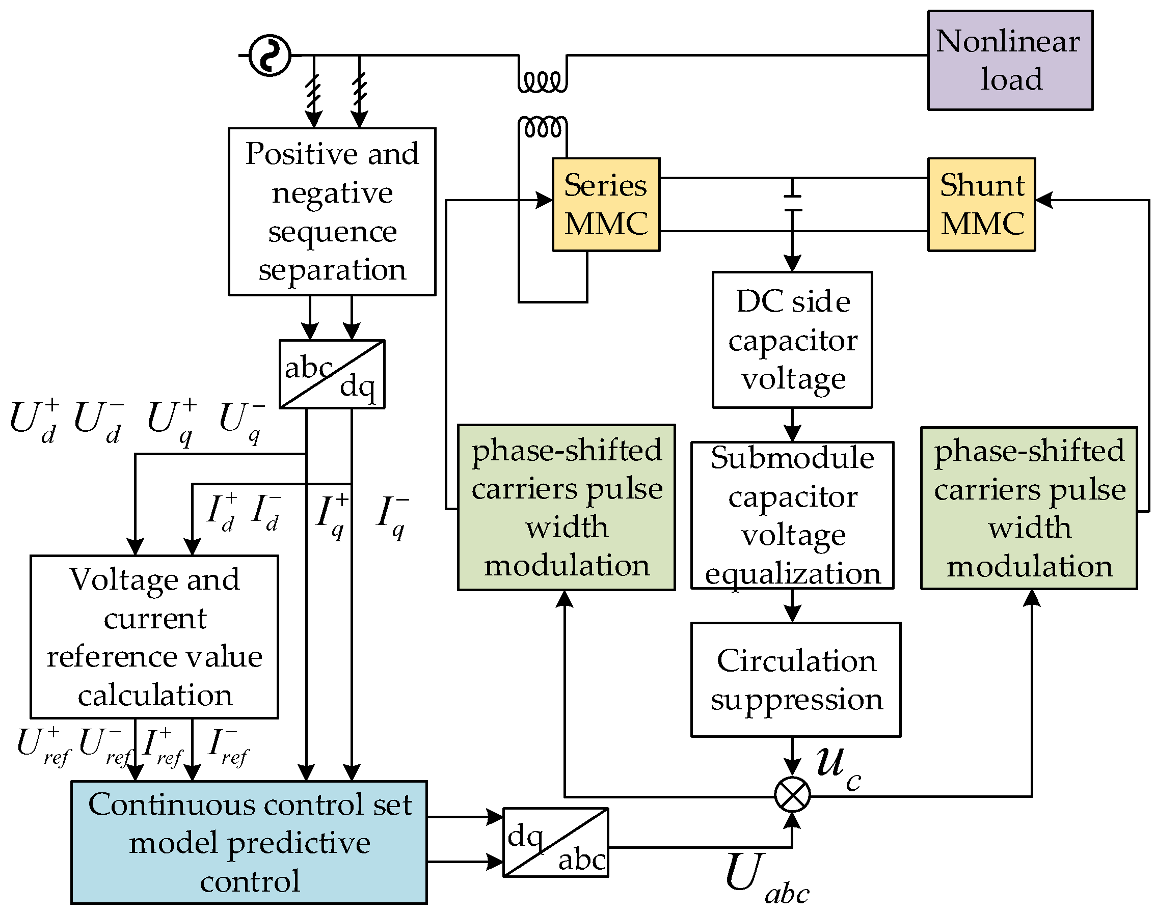
3.2. Overall Control Diagram of MMC-UPQC

The overall control block diagram of the MMC-UPQC system is shown in Figure 2. First, the voltage and current signals on the AC side are obtained and processed through dq transformation and positive and negative sequence separation to acquire the voltage and current signals in the rotating reference frame. These signals are then used to calculate the reference values for voltage and current. Subsequently, a continuous-control-set model predictive control module is applied. The resulting control signals, together with those derived from submodule capacitor voltage balancing and circulating current suppression, are input into a phase-shifted carrier pulse-width modulation (PSC-PWM) scheme to generate control signals for the MMC.
When voltage fluctuations occur in the power grid, the series-side MMC injects compensating voltage to stabilize the load voltage. Similarly, when abnormal current is detected, the shunt-side MMC provides compensating current to maintain grid current stability. Since voltage and current disturbances in the power grid are continuous and dynamic in nature, the corresponding compensation signals must also vary in real time. Therefore, the control strategy must exhibit a fast dynamic response to ensure that the MMC-UPQC system can continuously and accurately track the required compensation signals, thereby effectively maintaining power quality.

4. Simulation Analysis

To verify the effectiveness and feasibility of the CCS-MPC proposed in this paper, a simulation model is built on the MATLAB/Simulink platform. The parameters of the simulation model are shown in Table 1. Three different operating conditions are set: grid voltage sag and swell, high-order harmonic injection, and a composite condition involving grid-side voltage sag/swell and nonlinear load connection. The compensation performance of PI control, PBC, and CCS-MPC is analyzed and compared. All three control strategies adopt the PSC-PWM strategy. The grid line voltage is set to 2 kV in the experiment to verify the system performance under medium- and high-voltage conditions.
As discussed in [20], FCS-MPC requires 2 2 N rolling optimizations per control cycle, where N is the number of submodules per arm. IFCS-MPC [22] reduces this to ( N + 1 ) 2 optimizations per cycle. The proposed CCS-MPC only requires one rolling optimization per cycle, regardless of the number of submodules. The relationship between the number of rolling optimizations per cycle and the number of submodules is summarized in Table 2. This clearly demonstrates that CCS-MPC has the lowest computational burden among the three approaches.

4.1. Single-Phase Grid Voltage Sag and Swell

The simulation is configured such that during the period from 0.05 s to 0.15 s, a 20% voltage sag occurs in phase a, and during the period from 0.15 s to 0.25 s, a 20% voltage swell occurs in phase a. Phases b and c maintain normal voltage levels throughout. The load-side voltage waveform is shown in Figure 3.
Figure 4 presents a comparison of load voltage and compensation voltage under PI control, PBC, and CCS-MPC when phase grid voltage undergoes sag and swell. As shown in the figure, the load voltage waveform under CCS-MPC is the smoothest, while both PBC and PI control introduce a certain degree of ripple in the load voltage. Regarding the compensation voltage, CCS-MPC yields the lowest ripple content. In contrast, PBC and PI control generate more ripple, and the compensation voltage waveform under PI control significantly deviates from the standard sinusoidal waveform.
As shown in Figure 5, the CCS-MPC exhibits the strongest harmonic suppression capability, reducing the THD to 1.07%, while PBC and PI control result in higher THD values of 1.77% and 2.66%, respectively.
Table 3 provides a detailed comparison of the voltage overshoot and the time required to restore the load voltage to a steady value under each control strategy.

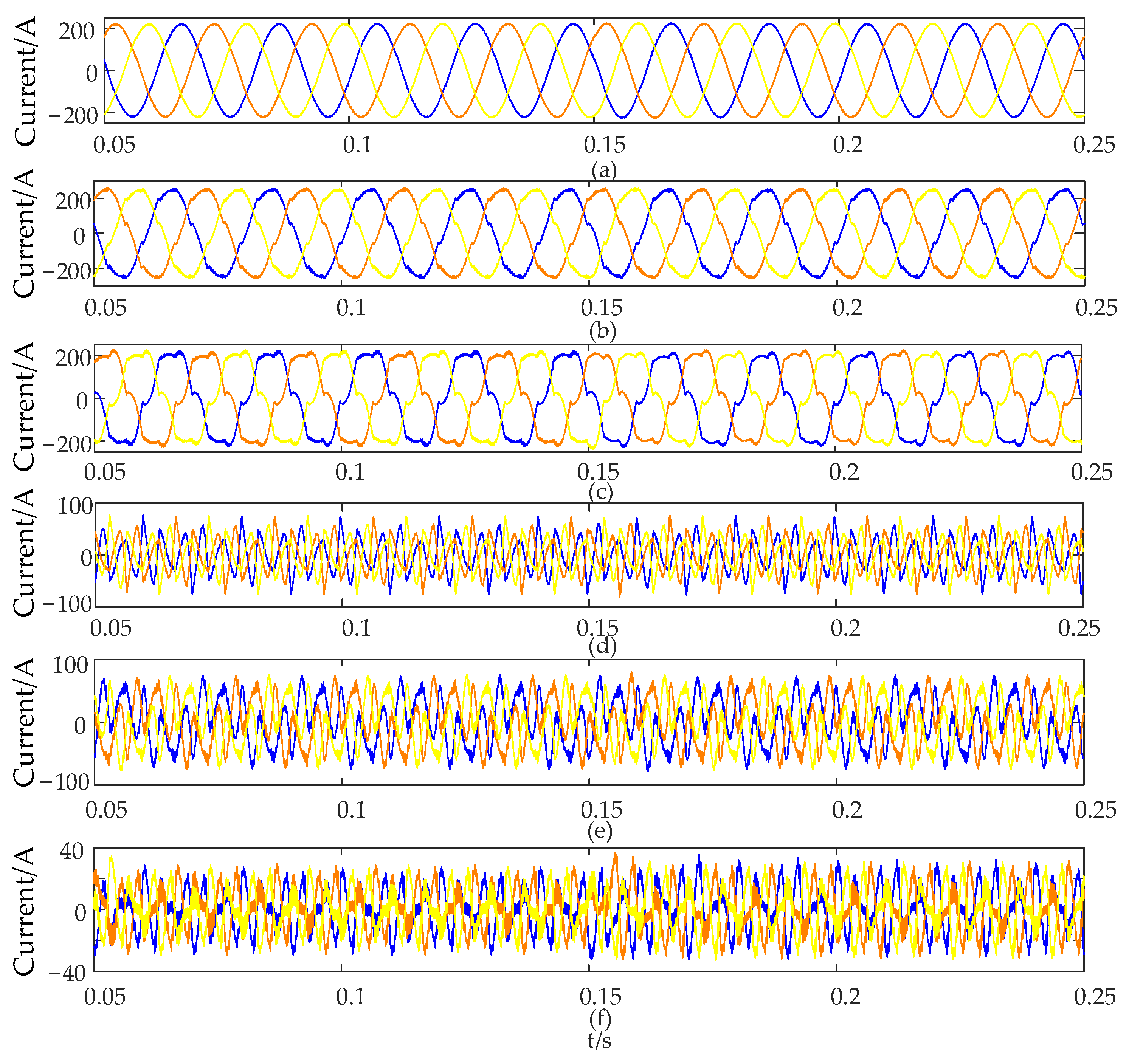
4.2. High-Order Harmonic Injection

To verify the harmonic suppression capability of CCS-MPC, the simulation is configured to inject a fifth-order harmonic with an amplitude of 200 V and a seventh-order harmonic with an amplitude of 100 V during the period from 0.05 s to 0.25 s. The output waveform of the grid voltage is shown in Figure 6.
Figure 7 shows a comparison of load voltage and compensation voltage under PI control, PBC, and CCS-MPC after high-order harmonic injection into the grid-side voltage. As seen from the figure, the load voltage under CCS-MPC is closest to the sinusoidal waveform, while the output waveforms under PBC and PI control still deviate from the standard sinusoidal waveform. In terms of compensation voltage, CCS-MPC exhibits the least ripple, while PBC has the most ripple, indicating that CCS-MPC offers the highest compensation accuracy.
As shown in Figure 8, without compensation for the grid-side voltage, the THD of the load-side voltage reaches 11.18%. When the CCS-MPC strategy is applied, the THD is reduced to 1.44%. Due to the significant ripple present in the compensation voltage of PBC, the THD of the load voltage under PBC compensation is higher than that under PI control, reaching 7.48%, while the THD under PI control is slightly lower at 5.04%.
Table 4 provides a detailed comparison of the load-side voltage overshoot and the time required to recover to the steady-state value under each control strategy.

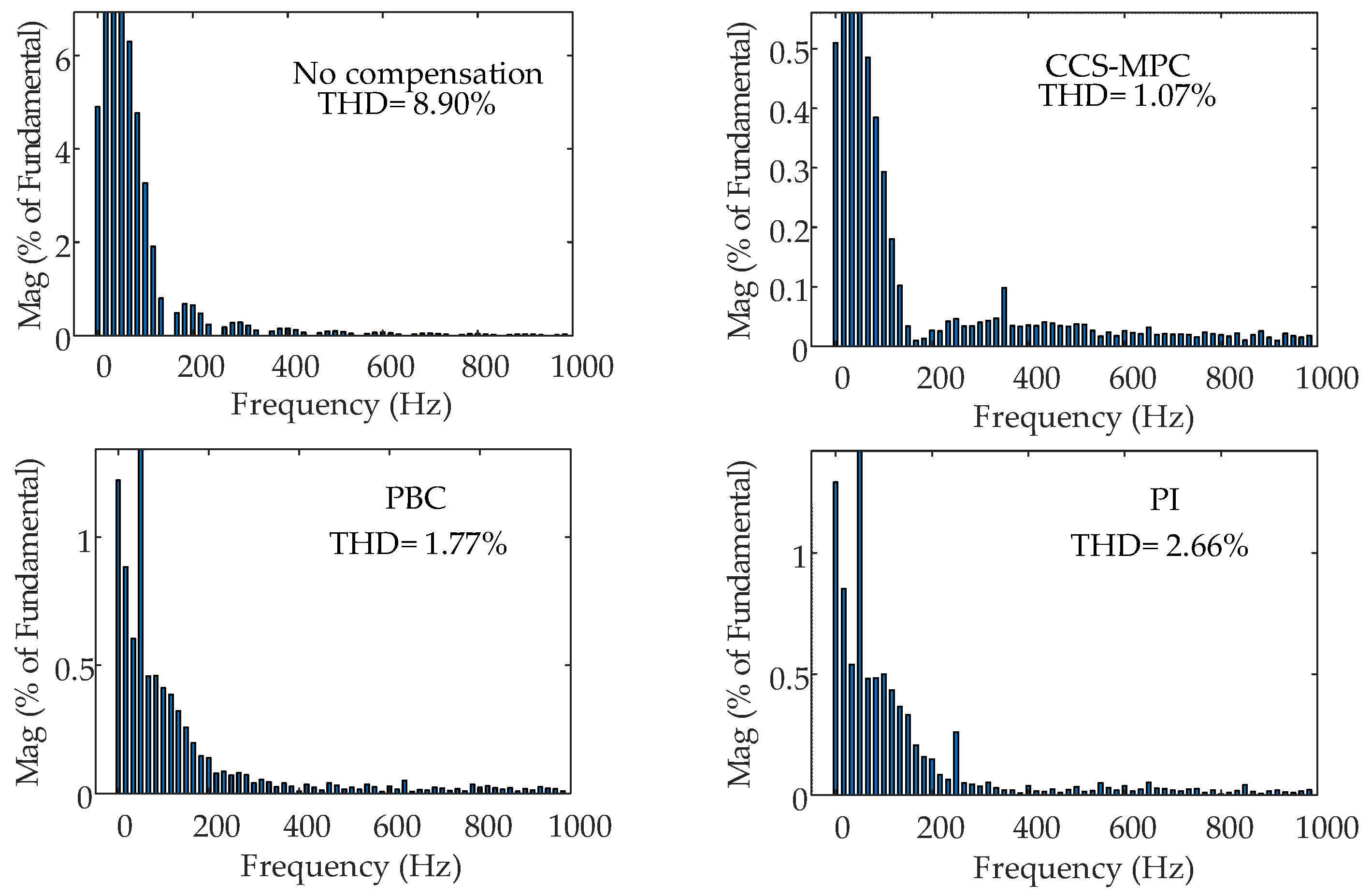
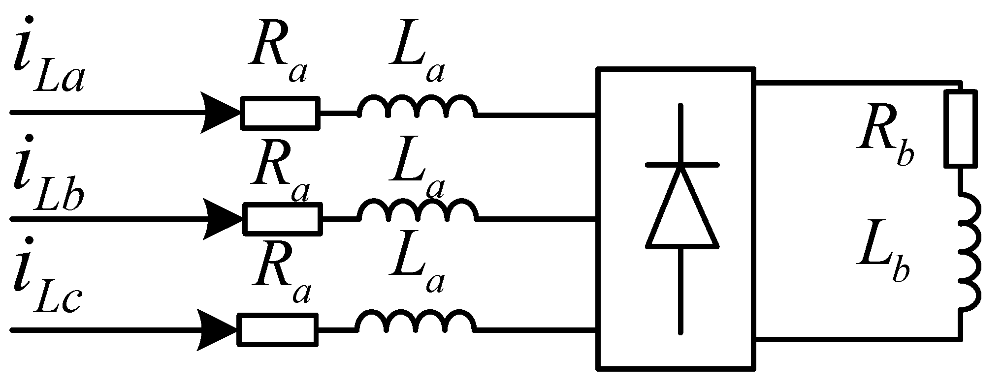
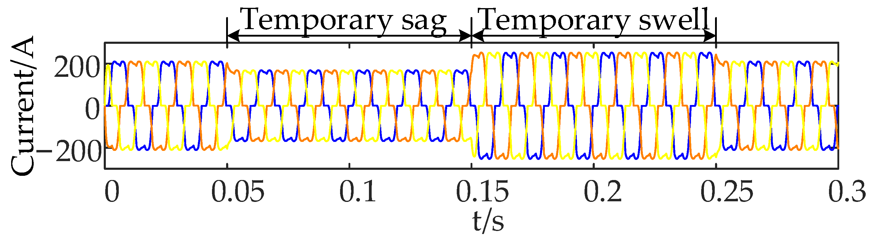
4.3. Grid Voltage Sag and Swell with Nonlinear Load

To verify the compensation capability of the system under CCS-MPC when subjected to a composite condition involving the connection of a nonlinear load and grid-side voltage sag and swell, the simulation is configured as follows: at 0.05 s, the grid-side voltage drops by 20%; at 0.15 s, the voltage rises by 20% compared to the normal value; and at 0.25 s, it returns to the nominal level. The connection method of the nonlinear load is shown in Figure 1, and the specific circuit configuration is shown in Figure 9. Figure 10 illustrates the grid-side current without compensation.
Figure 11 shows the comparison of grid-side current and compensation current under PI control, PBC, and CCS-MPC in a composite condition involving nonlinear load connection and grid-side voltage sag and swell. As can be seen from the figure, the compensation current under CCS-MPC is the smoothest, with the lowest ripple content, resulting in a compensated grid-side current that is closest to the ideal sinusoidal waveform. In contrast, the compensation current produced by PBC exhibits more noticeable ripple, making the compensated waveform less smooth and still some distance from the standard sinusoidal shape. Under PI control, the compensation current not only has high ripple content but also reaches only half the amplitude of the other two control strategies, leading to poor compensation performance.
As shown in Figure 12, without compensation of the grid-side current, the THD of the grid-side current reaches as high as 20.19%. When the CCS-MPC strategy is applied for compensation, the THD can be reduced to 1.34%. Due to the high ripple content in the compensation current under PBC and its deviation from the ideal sinusoidal waveform, the THD can only be reduced to 6.66%. In contrast, PI control provides almost no effective compensation, resulting in a THD as high as 15.59%.
Table 5 provides a detailed comparison of the grid-side current overshoot and the time required to recover to the steady-state value under each control strategy.

5. Conclusions

To address the issue of low compensation accuracy in MMC-UPQC under traditional control methods, this paper proposes a continuous-control-set model predictive control (CCS-MPC) strategy. A simulation model was developed, and the proposed method was compared with the linear control strategy (PI control) and the nonlinear control strategy (passive-based control, PBC) under two single working conditions and one composite working condition. The simulation results led to the following conclusions:
(1)
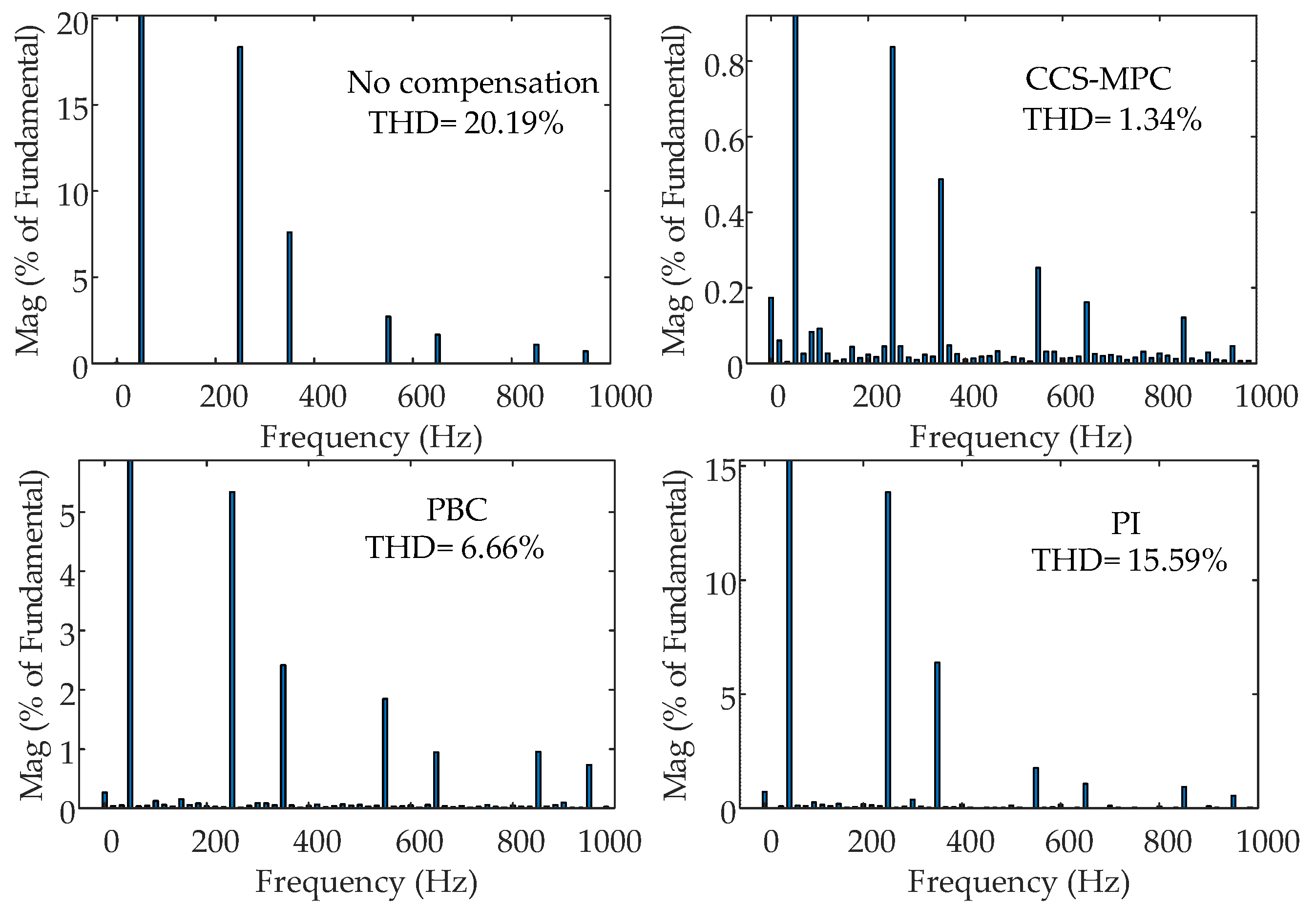
CCS-MPC can fully utilize its fast response advantage, enabling MMC-UPQC to quickly and accurately track the required compensation signals. This allows the series-side MMC to output more precise compensation voltage and the shunt-side MMC to output more precise compensation current, effectively reducing the THD of the load-side voltage and grid-side current.
(2)
Compared with PI control and PBC, CCS-MPC exhibits higher compensation accuracy, stronger harmonic suppression capability, and superior performance in handling complex operating conditions.

Author Contributions

Conceptualization, methodology, software, formal analysis, data curation, and writing—original draft preparation, L.C.; validation, writing—review and editing, and funding acquisition, J.Z. (Jianping Zhou); supervision, J.Z. (Jiayu Zhai), L.Y., X.Q. and Z.T. All authors have read and agreed to the published version of the manuscript.

Funding

This research was funded by the National Science Foundation of China (62473247).

Data Availability Statement

The original contributions presented in the study are included in the article. Further inquiries can be directed to the corresponding author.

Conflicts of Interest

The authors declare no conflicts of interest.

References

  1. Wang, F.; Quan, X.; Ren, L. Review of power quality disturbance detection and identification methods. Proc. CSEE 2021, 41, 4104–4121. [Google Scholar]
  2. He, J.; Meng, W.; Jiang, W.; Yin, X. Power quality problems in renewable energy power distribution systems: Analysis and solutions. High Volt. Eng. 2023, 49, 2983–2994. [Google Scholar]
  3. Khadkikar, V. Enhancing electric power quality using UPQC: A comprehensive overview. IEEE Trans. Power Electron. 2012, 27, 2284–2297. [Google Scholar] [CrossRef]
  4. Fuyin, N.; Zhengming, L. Overview of unified power quality conditioner research development. Power Syst. Prot. Control. 2020, 48, 177–187. [Google Scholar]
  5. Lu, J.; Xiao, X.; Zhang, J.; Xu, Y. MMC-UPQC coordinated control method based on fixed active current limit value control. Trans. China Electrotech. Soc. 2015, 30, 196–203. [Google Scholar]
  6. Isik, S.; Alharbi, M.; Bhattacharya, S. An optimized circulating current control method based on PR and PI controller for MMC applications. IEEE Trans. Ind. Appl. 2021, 57, 5074–5085. [Google Scholar] [CrossRef]
  7. Yang, Y.; Xiao, X.; Guo, S.; Gao, Y.; Yuan, C.; Yang, W. Energy storage characteristic analysis of voltage sags compensation for UPQC based on MMC for medium voltage distribution system. Energies 2018, 11, 923. [Google Scholar] [CrossRef]
  8. Liu, H.M.; Jiang, C.H.; Cheng, Q.M. Research on integrated management of MMC-UPQC power quality based on passivity control under unbalanced grid. High Volt. Eng. 2021, 47, 1344–1355. [Google Scholar]
  9. Wang, Y.; Cheng, Q.; Cheng, Y. Passivity-based control of MMC-based active power filter under non-ideal conditions. Int. Trans. Electr. Energy Syst. 2020, 30, e12178. [Google Scholar] [CrossRef]
  10. Ma, X.; Cheng, Q.; Cheng, Y.; Rui, X.; Zhao, J. Dual-passivity-based control strategy of modular multilevel matrix converter. Int. Trans. Electr. Energy Syst. 2021, 31, e12692. [Google Scholar] [CrossRef]
  11. Zhou, J.; Zhou, J.; Yang, H.; Huang, L. Passive Super-Twisting Second-Order Sliding Mode Control Strategy for Input Stage of MMC-PET. Energies 2024, 17, 2036. [Google Scholar] [CrossRef]
  12. Jiang, C.; Zhang, S. Power quality compensation strategy of MMC-UPQC based on passive sliding mode control. IEEE Access 2022, 11, 3662–3679. [Google Scholar] [CrossRef]
  13. Yang, X.; Chen, W.; Yin, C.; Cheng, Q. Fractional-Order Sliding-Mode Control and Radial Basis Function Neural Network Adaptive Damping Passivity-Based Control with Application to Modular Multilevel Converters. Energies 2024, 17, 580. [Google Scholar] [CrossRef]
  14. Qiming, C.; Weisha, S.U.N.; Yinman, C. Nonlinear control strategy based on Lyapunov function for MMC under grid voltage unbalance condition. High Volt. Eng. 2019, 45, 3984–3992. [Google Scholar]
  15. Cheng, Q.; Jiang, C.; Wang, Y. Lyapunov function control strategy of MMC-SAPF under non-ideal conditions. Electr. Power Autom. Equip. 2020, 40, 68–79. [Google Scholar]
  16. Ghadi, R.J.; Mehrasa, M.; Adabi, M.E.; Bacha, S. Lyapunov theory-based control strategy for multi-terminal MMC-HVDC systems. Int. J. Electr. Power Energy Syst. 2021, 129, 106778. [Google Scholar] [CrossRef]
  17. Chang, J.; Qiming, C.; Qiao, M. Differential flat control for unified power quality controller based on modular multilevel converter under unbalanced grid voltage. Trans. China Electrotech. Soc. 2021, 36, 3410–3421. [Google Scholar]
  18. Bo, L.I.N.; Bin, W.; Qiming, C. Differential flatness controller strategy of MMC-HVDC to supply power to passive network under asymmetric faults. High Volt. Eng. 2021, 47, 4023–4032. [Google Scholar]
  19. Zhou, D.; Tu, P.; Qiu, H.; Tang, Y. Finite-control-set model predictive control of modular multilevel converters with cascaded open-circuit fault ride-through. IEEE J. Emerg. Sel. Topics Power Electron. 2019, 8, 2943–2953. [Google Scholar] [CrossRef]
  20. Gong, Z.; Dai, P.; Yuan, X.; Wu, X.; Guo, G. Design and experimental evaluation of fast model predictive control for modular multilevel converters. IEEE Trans. Ind. Electron. 2015, 63, 3845–3856. [Google Scholar] [CrossRef]
  21. Bocker, J.; Freudenberg, B.; The, A.; Dieckerhoff, S. Experimental comparison of model predictive control and cascaded control of the modular multilevel converter. IEEE Trans. Power Electron. 2014, 30, 422–430. [Google Scholar] [CrossRef]
  22. Zhang, J.; Zeng, G.; Zhao, J.; Huang, B.; Xiao, B. Modular multilevel converter capacitor voltage balancing strategy based on improved bubble sorting. Power Syst. Prot. Control 2020, 48, 92–99. [Google Scholar]
  23. Zhou, D.; Yang, S.; Tang, Y. Model-predictive current control of modular multilevel converters with phase-shifted pulse width modulation. IEEE Trans. Ind. Electron. 2018, 66, 4368–4378. [Google Scholar] [CrossRef]
  24. Wang, Z.; Yin, X.; Chen, Y. Model predictive arm current control for modular multilevel converter. IEEE Access 2021, 9, 54700–54709. [Google Scholar] [CrossRef]
  25. Wang, F.; Wei, Y.; Young, H.; Ke, D.; Xie, H.; Rodríguez, J. A continuous-control-set type model-free predictive current control based on time-series for permanent magnet synchronous motor drives. Trans. China Electrotech. Soc. 2023, 38, 6027–6038. [Google Scholar]
  26. Karimi, M.H.; Rostami, M.A.; Zamani, H. Continuous control set model predictive control for the optimal current control of permanent magnet synchronous motors. Control Eng. Pract. 2023, 138, 105590. [Google Scholar] [CrossRef]
Figure 1. Overall structure of MMC-UPQC.
Energies 18 02946 g001
Figure 2. Overall control diagram of MMC-UPQC.
Energies 18 02946 g002
Figure 3. Load-side voltage under single-phase grid voltage sag and swell.
Energies 18 02946 g003
Figure 4. Performance comparison of three control strategies for voltage compensation on the series side of MMC-UPQC under unbalanced grid conditions: (a) load voltage response using CCS-MPC; (b) load voltage response using PBC; (c) load voltage response using PI control; (d) compensation voltage generated by CCS-MPC; (e) compensation voltage under PBC; (f) compensation voltage under PI control.
Energies 18 02946 g004
Figure 5. FFT analysis of load voltage.
Energies 18 02946 g005
Figure 6. Load-side voltage under high-order harmonic injection condition.
Energies 18 02946 g006
Figure 7. Performance comparison of three control strategies for voltage compensation on the series side of MMC-UPQC under high-order harmonic injection conditions: (a) Load-side voltage waveform using the proposed CCS-MPC method. (b) Load-side voltage waveform under PBC. (c) Load-side voltage waveform under PI control. (d) Compensation voltage generated by CCS-MPC. (e) Compensation voltage obtained using PBC. (f) Compensation voltage using PI control.
Energies 18 02946 g007
Figure 8. FFT analysis of load voltage.
Energies 18 02946 g008
Figure 9. Nonlinear load.
Energies 18 02946 g009
Figure 10. Grid side current without compensation.
Energies 18 02946 g010
Figure 11. Comparative analysis of three control strategies for current compensation on the shunt side of MMC-UPQC under grid voltage sag and swell conditions with a nonlinear load: (a) grid-side current using the proposed CCS-MPC; (b) grid-side current using PBC; (c) grid-side current using PI control; (d) compensation current generated by CCS-MPC; (e) compensation current using PBC; (f) compensation current using PI control.
Energies 18 02946 g011
Figure 12. FFT analysis of grid current.
Energies 18 02946 g012
Table 1. Experimental parameters.
System ParameterParameter Values
Number of bridge-arm submodules (N)6
Grid-side line voltage/kV2
Sub-module capacitance/mF1.2
Bridge-arm inductance/mH4
DC-side capacitance voltage/kV6
DC-side capacitance/mF12
Series-side inductance/mH2
Shunt-side inductance/mH3
Series-side resistance/Ω0.1
Shunt-side resistance/Ω0.2
Transformer ratio1
Table 2. Rolling optimization count per control cycle for three MPC strategies.
N246810
CCS-MPC11111
IFCS-MPC9254981121
FCS-MPC16256409665,5361,048,576
Table 3. Dynamic performance indicators of the grid voltage sag and swell.
Control StrategyOvershoot/%Recovery Time/s
CCS-MPC0.300.015
PBC1.400.030
PI3.500.075
Table 4. Dynamic performance indicators of the high order harmonic injection.
Control StrategyOvershoot/%Recovery Time/s
CCS-MPC0.800.015
PBC2.700.040
PI4.900.080
Table 5. Dynamic performance indicators of the grid voltage sag and swell with a nonlinear load.
Control StrategyOvershoot/%Recovery Time/s
CCS-MPC1.200.015
PBC3.700.045
PI5.200.090
Disclaimer/Publisher’s Note: The statements, opinions and data contained in all publications are solely those of the individual author(s) and contributor(s) and not of MDPI and/or the editor(s). MDPI and/or the editor(s) disclaim responsibility for any injury to people or property resulting from any ideas, methods, instructions or products referred to in the content.

