1. Introduction
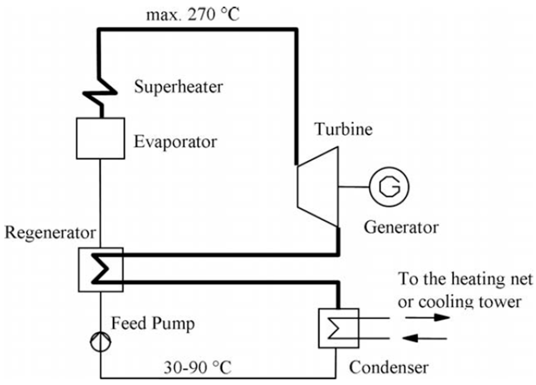
In the current context of a significant increase in the demand for electricity worldwide and the simultaneous need to reduce emissions of pollution and greenhouse gases to contain climate change, there is a need to produce energy through the use of renewable sources and energy systems as sustainable as possible. One of the most studied and developed technologies focuses on the use of waste heat with the application of renewable energy, to maximize energy production efficiency: this is the Organic Rankine Cycle (ORC). The ORC system is one of the most efficient systems for low-grade thermal energy conversion [
1]. It can be coupled with several renewable energy sources for a wide range of temperatures, and the basic system scheme is illustrated in
Figure 1.
ORC systems have several advantages [
2]: the structure is particularly simple and compact [
3], can be recovered from existing systems and has relatively low maintenance costs [
4,
5], is reliable, and is able to work with heat sources of medium-low thermal energy [
6]. Furthermore, there are many types of Organic Rankine Cycle architectures [
7]; taking into account several boundary conditions and pinch point differences, it is necessary to define technical characteristics and heat source temperatures between 20 °C and 450 °C to design an advanced cycle architecture, matching the temperature profile of the heat source and the working fluid of the plant.
The use of ORC systems is highly developed in the field of thermal energy production starting from solar energy. An example could be the study by Golonis et al. [
8] that focused on the match of an ORC engine and a CPVT (Concentrating Photovoltaic Thermal) system, to use the waste heat of the cooling circuit for domestic hot water (DHW) or for the production of electricity.
According to Gupta et al. [
3], the ORC systems seem to be one of the most reliable renewable energy-based technologies to satisfy major energy demands, with poly-generation plants with several outputs including heating, cooling, electricity, hydrogen, and desalination. For example, Zhao et al. [
9] also proposed a model for selecting the composition of mixed refrigerants and realized that simultaneous optimization of the composition applied to an ORC-VCR-CCHP (Organic Rankine Cycle–Vapour Compression Refrigeration-Combined cooling, heating, and power) system. This system can recover solar energy and convert it into cooling, heat, and electricity. Manolakos et al. [
10], instead, described an application of a solar ORC plant for water desalination purposes, and Permana [
11] presented a 4E analysis of a biomass-driven ORC and a performance evaluation, prediction analysis, and optimization of an experimental ORC using artificial neural networks (ANNs) [
12].
In the temperature range of 80–200 °C, Organic Rankine Cycles are regarded as one of the most suitable technologies for converting low-temperature heat into work [
13] and are very attractive when linked to renewable thermal energy production systems such as concentrated solar energy using parabolic trough collectors for medium temperature applications [
14,
15,
16]. Helvaci et al. [
17] designed and experimentally tested a solar ORC with a flat-plate collector as an evaporator to supply heat to the fluid, and it acts as a direct vapour generator in the cycle; energy and exergy efficiency of the solar ORC were calculated as 3.81% and 17.8%, respectively. The results of the study show a convenient use of small-scale solar systems not only for the production of mechanical energy but also thermal energy, using HFE 7000 as a working fluid.
Another valid system is the micro-ORC powered by solar energy, which is one of the most effective tools for distributed generation and Positive Energy Districts (PEDs). Significant advancements have been made over the years in both solar collectors [
18,
19,
20] and thermal storage for residential applications [
21]. These developments further enhance the appeal of micro-ORC systems.
The applications of the ORC system can be advantageous when also combined with other renewable technologies, like dry gasification oxy-combustion with CO
2 [
22] or geothermal energy [
23]. Heberle et al. [
24] elaborated an LCA (Life Cycle Assessment) for various geothermal ORC powerplant concepts and working fluids. Referring to existing plants in Germany, they compared the use of a low-GWP refrigerant to common fluorinated working fluids like 245fa; depending on the geographical position and the type of geothermal source, different operating conditions were analyzed, but, in any case, low-GWP working fluids like hydrocarbons R-1233zd or R-1234yf seem to be a promising alternative for substituting R-245fa.
One of the biggest advantages of the ORC system is its use with different types of heat sources, and another of the very efficient uses of this system is with the exploitation of heat waste deriving from an internal combustion engine, as in the review of Shi et al. [
25], from immersion cooling in data centres, as in the recent study by Zhou et al. [
26], or from other industrial processes.
As regards the fluids used in an ORC plant, the paper of Bao et Zhao [
27] offers an overview of working fluid selection (including pure fluids and mixtures) and the choice of the expansion turbine. The working fluid used affects the behaviour of the system and the choice of the most appropriate depends on the heat source types, temperature level, and the performance indexes. Lakew and Bolland [
13] analyzed, on the basis of heat sources used, components of the plant (turbine and heat exchangers) and power production capability, various working fluids like R134a, R123, R227ea, R245fa, R290, and n-pentane in a simple Rankine cycle. They found that. for temperature around 160 °C, R24fa produces a higher work output and an optimal evaporator pressure, depending on the heat source temperature.
Garg et al. [
28] carried out a thermodynamic analysis of an ORC with isopentane, R-245fa, and their mixtures like working fluids, with a heat source in a range of temperatures between 380 and 425 K. They found a molar concentration of 70% isopentane and 30% R-245fa as the best combination to have the lower flammability of the former and the lower GWP of the latter, and the turbine remains the major source of losses due to irreversibility of the system.
The first part of the study [
29] referred to the choice and use of a scroll compressor as a system expansion turbine, as it is one of the most influential components within the plant. The expander is a key component in an ORC system. Depending on the operating conditions and the size of the system, the most suitable type of expander is selected, mainly either dynamic (turbo) or displacement (volumetric). The scroll-type expander appears to be the most suitable for ORC systems. This is primarily because of its reduced number of moving parts, its reliability, and its wide output power range [
30].
There are several theoretical and experimental studies on the use of the scroll expander within these systems: the scroll-type expander is a promising candidate for micro-scale (<10 kW) trans-critical CO
2 waste heat recovery power systems, as Du et al. [
31] reported. Tsai et al. [
32] focused on realizing a micro-scale ORC plant to demonstrate that the 0.3 kW micro-ORC can achieve similar working output as predicted in a large-scale ORC, and Lemort et al. [
33] carried out a theoretical analysis of a scroll expander for the construction of a semi-empirical model to calculate the mass flow rate, the shaft power, and the exhaust temperature.
Many numerical studies on ORC systems of can be found in the literature, accompanied by comparisons with experimental results for the validation and analysis of the systems. Xu et al. [
34] focused, with a numerical simulation, on the output power and isentropic efficiency of the expander, varying the inlet and outlet temperatures and pressures and the rotation speed. Emhardt et al. [
35], with a CFD model, found an optimum point at a pressure ratio of the expansion of 3.5.
Instead, Zhang et al. [
36] focused on a dynamic analysis of a biomass-fired ORC combined heat and power (CHP) system under two different control strategies with a dynamic model using Simulink software: the study offers an interesting new approach to the use of biomass in ORCs and in operation control.
Gao et al. [
37] investigated various displacements of scroll expanders using thermodynamic and heat transfer models. They conducted experiments and simulations on an ORC system with a heat source temperature of 105 °C to determine the isentropic efficiency, and the scroll expander used was modified from an automobile air conditioning compressor. Then, they developed thermodynamic and heat transfer models of the ORC and a prototype. The experiments revealed that the system’s energy efficiency ranged from 1.7% to 3.2%, while the exergy efficiency was between 8.6% and 16.9%.
Quoilin et al. [
38] discussed a numerical and experimental analysis of a small scale ORC operating with R123 working fluid: the study defines a semi-empirical model of an ORC system, involving a relatively limited number of parameters. The comparison between predicted values of the model and experimental results shows a fairly good agreement. Furthermore, the experimental data show a promising isentropic effectiveness of the expander and the feasibility of using a compressor as an expander in a small-scale ORC.
The use of a compressor present in the automotive market for air conditioning systems as an expander allows a reduction in manufacturing costs and avoids the design of a new one. The design process is fundamental for choosing all the components and obtaining an efficient and cost-effective plant.
Modelling and design of the developed micro-ORC system may require considerations on scalability for larger applications, both from a numerical modelling perspective and in terms of actual operation.
The numerical model proves valuable not only for small-scale systems but also for industrial-scale applications, as it provides an accurate thermodynamic description. This ensures that the model remains conservatively predictive on different scales and can be effectively extended to industrial applications to characterize thermodynamic behaviour. Large-scale ORC systems are already well established, especially in industrial applications, while micro-ORC systems remain a minority technology in the residential sector. Consequently, components for large-scale ORC systems are specifically designed for this purpose and are widely available. In contrast, the micro-ORC prototype under consideration relies on components that were not originally designed for this application, resulting in performance losses. Industrial-scale ORC systems benefit from more suitable pumping technologies, such as screw pumps, which offer greater efficiency and applicability than the vane pump used in the micro-ORC system. The use of purpose-built components would reduce losses and improve the overall efficiency of the system.
This work was developed in two parts: the first part [
29] presents the characterization of a scroll expander for a low-cost small-scale ORC power plant application to establish the mechanical and thermodynamic conventional parameters as the filling factor and isentropic effectiveness. In the second part, a numerical model is presented, for defining the layout of the prototype, the design working conditions, and analyzing the best management strategies that maximize the performance. Thus, while Part 1 [
29] underlines the specific characteristics of the chosen scroll expander, Part 2 highlights the numerical modelling performed upstream of this work and the setup of the test bench, with its sensors and instruments. The final aim of this work is to describe the processes that led to the realization of the ORC prototype and the numerical model used to outline the influence of the boundary conditions on the performance of the system.
The use of scroll expanders in micro-ORC systems has gained increasing attention due to their compactness, low noise, and potential for cost-effective energy recovery [
39]. While scroll compressors are well established in HVAC applications, their adaptation as expanders presents a number of challenges and opportunities.
This study focuses on the experimental characterization of a modified scroll device operating as an expander in a micro-ORC setup. Particular emphasis is placed on the selection and optimization of the plant, considering that the thermodynamic properties of the fluid greatly affect the expander’s performance, internal leakage, and isentropic efficiency. R245fa is evaluated due to its low GWP and suitability for low-grade heat sources. The experimental campaign investigates the effects of operating conditions—including pressure ratios, inlet temperatures, and rotational speeds—on the expander’s performance. Furthermore, this study explores optimization strategies for matching the expander’s geometry and internal volume ratio to the selected fluid and application-specific conditions, aiming to improve overall cycle efficiency and expand the applicability of scroll-based micro-ORC systems.
2. Description of the Numerical Model
In this study, a numerical approach was used to outline and quantify the energy fluxes in an ORC plant and to facilitate the design of all components of the circuit. The aim was to achieve an accurate and comprehensive understanding of the thermodynamic behaviour and efficiency of the system. A detailed numerical model was developed using the software Microsoft Excel® implemented with the functions for calling the NIST REFPROP thermodynamic libraries: these libraries provide precise thermodynamic properties for various fluids, which are essential for the accurate modelling of the ORC.
The software solves different steady-state working conditions and allows for analysis of the sensitivity of the system changing different boundary conditions; in this way, it is possible to understand how the ORC responds to changes in operational parameters, such as working fluid properties, heat source temperatures, or ambient conditions. By analyzing the sensitivity of the system to these different boundary conditions, it is possible to optimize the ORC design for maximum efficiency and performance.
The model not only helps in predicting the performance of the ORC system under existing conditions but also aids in identifying potential areas for improvement. By simulating various design configurations and operating conditions, the model can highlight the impact of different design choices on overall system efficiency. This can lead to innovations in component design, such as more efficient heat exchangers or better working fluids, ultimately contributing to the advancement of ORC technology.
Every component is described by a set of equations that represents the thermodynamic transformations and the conservation of mass. The equations used in the model for the analysis of the cycle operation are (1) and (2), defined below.
2.1. Assumptions Adopted
The main assumptions adopted are that there are no pressure drops in the cycle circuit and no heat loss from any components to the environment.
The first assumption has the effect that the pressure ratio at the expander inlet is incremented compared to the real case. A preliminary investigation assuming a 5% pressure drop in each heat exchanger, carried out in the study of [
39], outlines an 18% decrease in pressure ratio at the expander and a 14% decrease in output power in a regenerative cycle.
The second assumption is also commonly accepted because the working temperatures are quite low, and the system should be thermally insulated from the surrounding ambient.
The working fluid chosen is R245fa because it presents the best characteristics for coupling with a thermal energy source at a temperature of 150 °C that could be easily reached with a small parabolic trough collector.
The fluid, from the propane series, consists of a single component and exhibits a high degree of thermal and hydrolytic stability under various operating conditions, both in contact with metals and in contact with water and air [
40]. The fluid chosen is particularly suited to the intended application because it adapts perfectly to the operating temperature levels set in the boundary conditions, the operating pressures are compatible with the circuit’s realization with commercial-type components, and it has high safety characteristics that are desirable for an experimental study phase in which the development of the prototype may present problems of leakage and breakage. Availability and low cost are not particular characteristics of this fluid [
41], but the high stability and, above all, the high vapour density balance the negative aspects, as it is possible to foresee a limited use of fluid within the system, to obtain a high power density per occupied volume, and, consequently, for residential applications, to realize systems of a size comparable to that of a refrigerator. Compared to alternatives such as R1234yf or R600a, this fluid initially offers advantages in terms of stability and energy density, making it a solid reference for the first stage of experimental validation. However, future tests and system configurations may explore alternative fluids with a lower Global Warming Potential (GWP) to optimize environmental sustainability without compromising system performance.
The isentropic efficiency of the expander was set equal to 0.7, and it could be changed as a function of the pressure ratio of the system once it is experimentally determined for the expander used in the application.
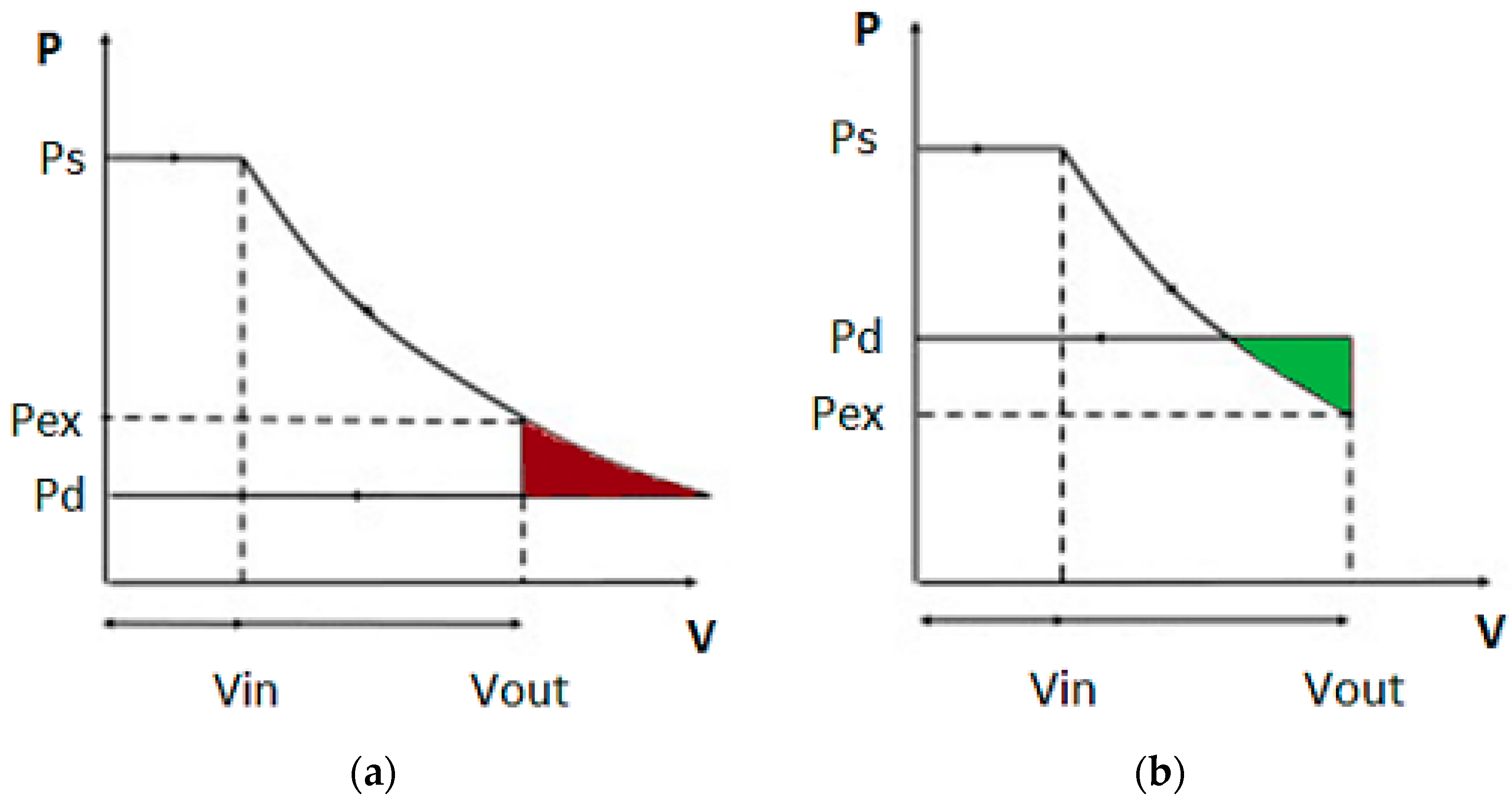
The pressure ratio was maintained constant at a specified value depending on the expander used. In fact, positive displacement devices have a volume ratio constrained by their geometry. The maximum isentropic efficiency of these devices is reached close to the pressure ratio defined by an adiabatic expansion process between these imposed volumes [
38,
39]. During the expansion, the working fluid was enclosed and guided in an expansion chamber. At discharge, the fluid will reach a pressure defined primarily by the geometry of the expander. If the condenser pressure is different from the expander discharge pressure, two cases would occur:
If it is lower, an isochoric pressure loss would take place. This is the case of under-expansion,
Figure 2a, and this condition could be associated with a loss of unused potential of the working fluid.
If it is greater, an isochoric pressure increase would take place. This is the case of over-expansion,
Figure 2b, and the expander should spend work to re-pressurize the working fluid to the condenser pressure.
2.2. Cycle Configuration
The cycle configuration is a classical Rankine cycle with the addition of regeneration. This is because the fluid used is a dry fluid, the saturated vapour curve presents decreasing entropy for decreasing pressure, and the introduction of a regenerative process increases the energetic efficiency of the system [
38]. A scheme of the cycle is shown in
Figure 3.
The expander is a key component in an ORC system; depending on the operating conditions and the size of the system, the most suitable type of expander was selected, mainly dynamic (turbo) and displacement (volumetric). Among the different volumetric machines, the scroll-type expander seems to be the most suitable in ORC systems. This is mainly due to the reduced number of moving parts, its reliability, and its wide output power range [
30]. As already highlighted in the previous work [
29], from a review of the literature [
39,
42,
43], once the plant boundary conditions and energy production objectives were defined, the most suitable expander for the situation is the scroll type, as illustrated in
Figure 4.
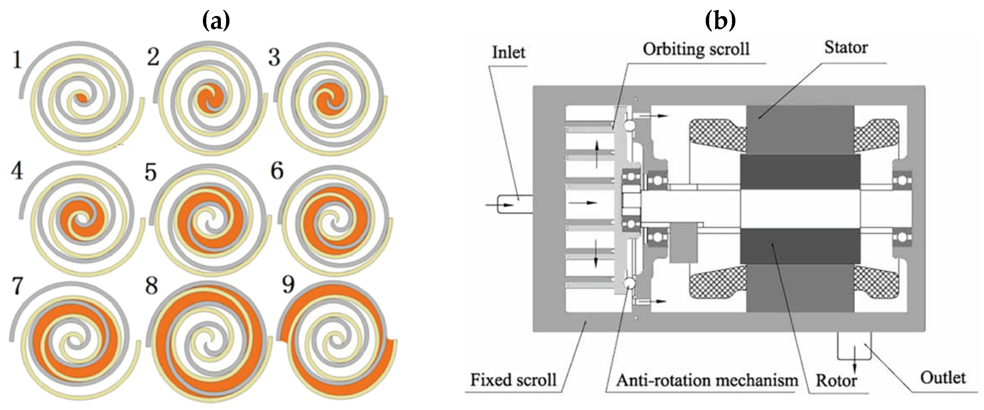
The scroll is a simple device, with very few moving parts; it uses two interleaving scrolls, one fixed and one orbiting eccentrically without rotating to generate variable volumes, in which the fluid can be compressed, pumped, or expanded. A scheme of the working principle is shown in
Figure 5a, in which the fluid evolution process is shown from the suction port to the discharge. Additionally, a typical structure of a scroll compressor is shown in
Figure 5b.
A fundamental parameter for the evaluation of the performance of a scroll expander is represented by the expansion ratio, a dimensionless parameter given by the ratio of the operating pressures of the system (evaporation and condensation pressure):
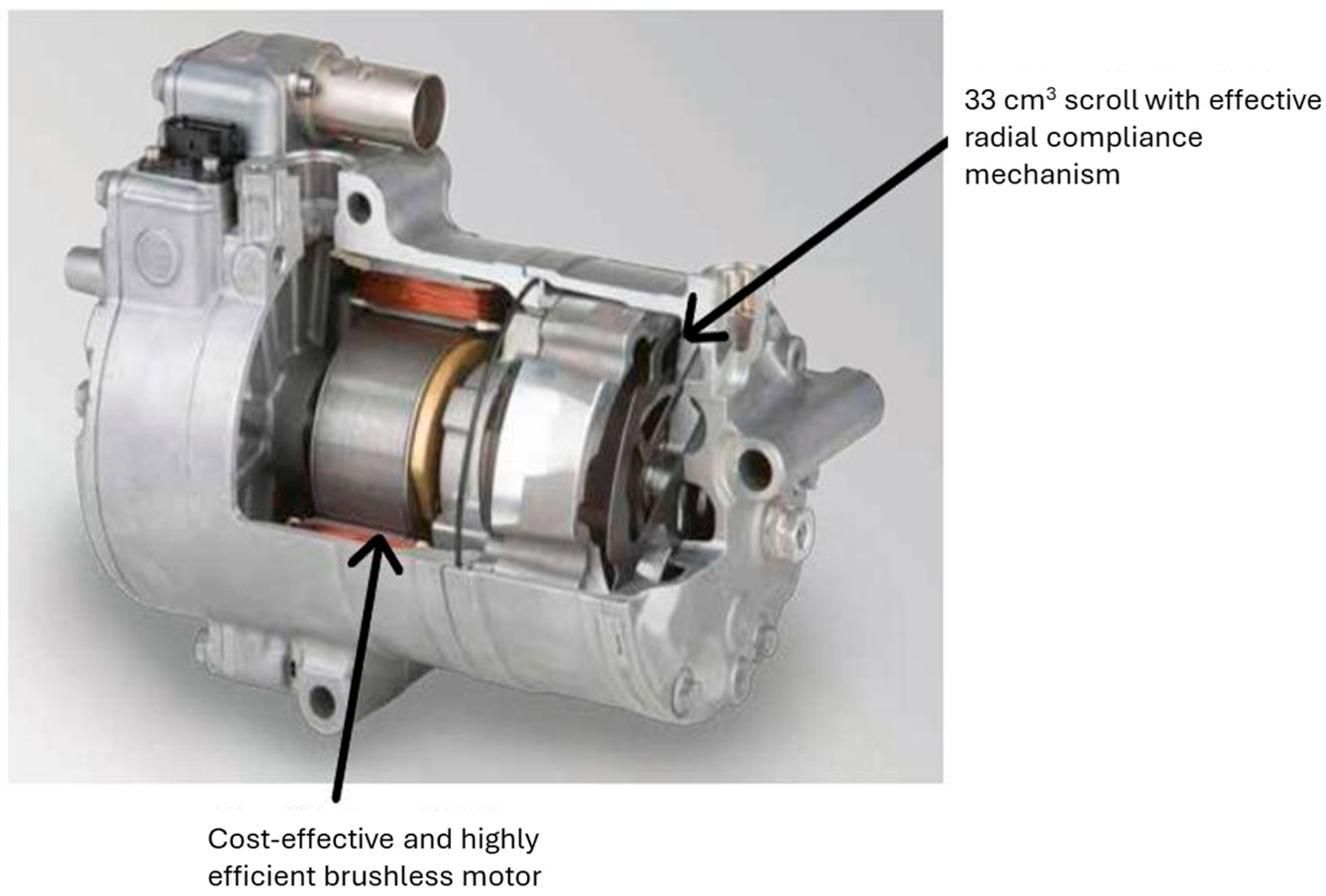
The machine selected for the application is a 33 cm
3 scroll compressor with the geometric ratio of the suction and discharge volume equal to 4; so, in expansion mode, the inlet volume of the expander is 8.25 cm
3. It consists of a hermetic scroll directly connected to a brushless three-phase motor that will be used as a generator. The model of the Sanden compressor used on the test bench is the SHS33 [
45],
Figure 6, with HFC-245fa working fluid.
2.3. Isentropic Enthalpic Efficiency
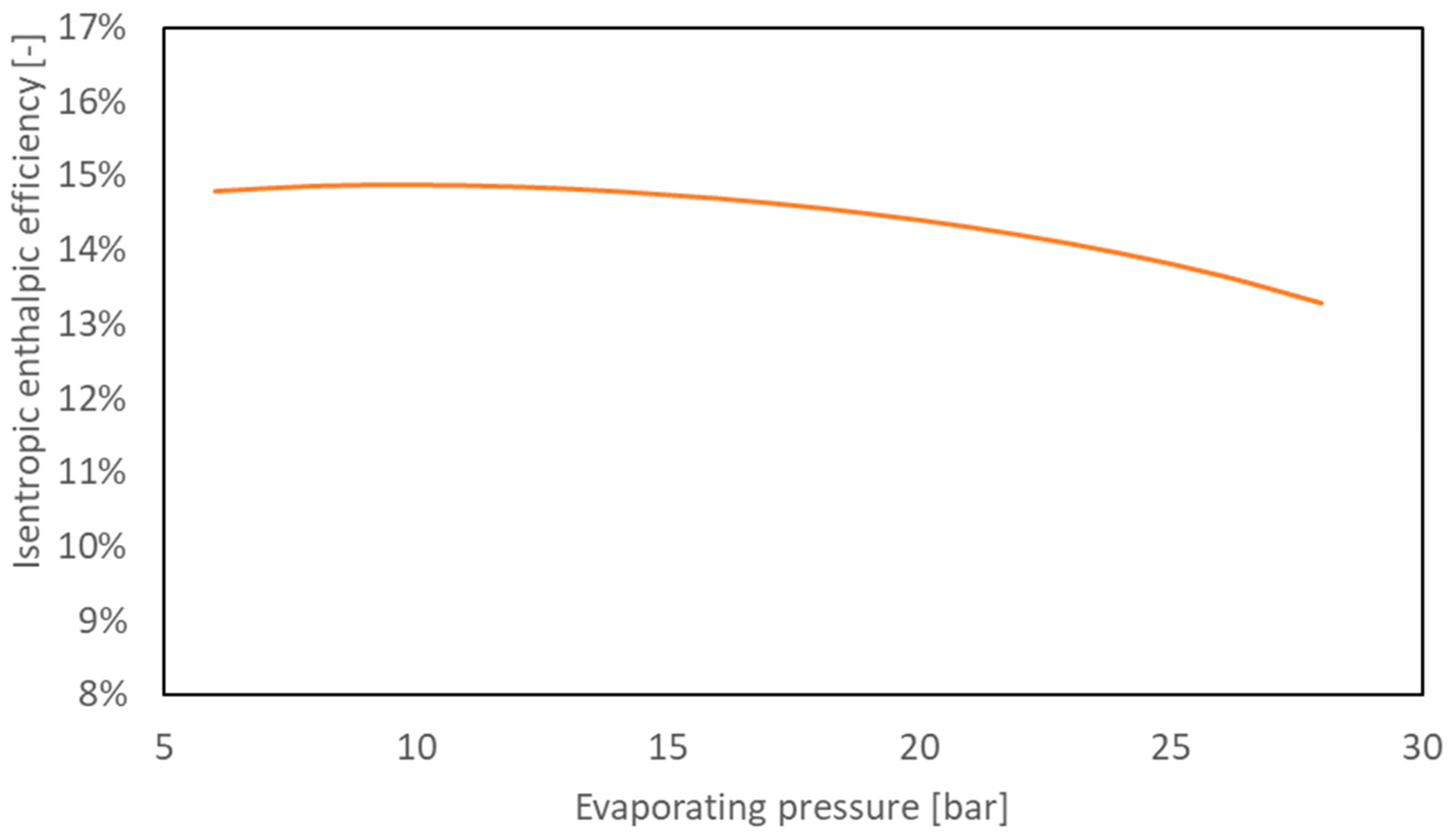
In this study, an important parameter is represented by the isentropic enthalpic efficiency: this is the ratio between the specific energy obtained with an ideal isentropic transformation in the expander and the specific energy required for evaporating the working fluid from the condition found at the regenerator outlet to the expander inlet condition.
This parameter is helpful to compare different working conditions of the system and evaluate the best strategy that maximizes the energy conversion efficiency of the system.
2.4. System’s Electrical Efficiency
The system’s electrical efficiency is defined as the ratio between the useful power generated by the plant and the heat required to evaporate the fluid entering the scroll. This parameter is influenced by the plant configuration because, with the same useful electrical power generated by the system, the amount of heat entering the thermodynamic cycle will be higher in the tri-generative configuration.
2.5. Pump Power and Back Work Ratio
The pump power, calculated with a fixed value of pump efficiency (0.85), is defined as follows in Equation (6):
This is a very important parameter to consider in the design of ORC plant, especially in a micro-scale application. In fact, the pump power could reach a significant percentage of the gross output power of the system, depending on the working condition of the system. For this reason, another parameter is defined: the back work ratio (BWR), which is the ratio of pump power and the gross output power from the system, as described in Equation (7).
The BWR is usually around 4% for a water Rankine cycle, but, with the use of organic working fluid, this parameter could reach values around 8% [
38]. This parameter could be more influential if a low-efficiency pumping system were used. There are many experimental studies, documented in the scientific literature, that report values for efficiency of the pumping system from 0.1 to 0.25 [
38,
46].
3. Results
The results obtained from the numerical model developed are expressed in the form of a sensitivity study that analyzes some important output parameters of the system, varying the boundary conditions of the application. The following parameters are maintained fixed:
Maximum cycle temperature.
Expansion ratio.
Isentropic efficiency.
RPM of the expander.
Pump efficiency (equal to 0.85).
Regeneration with heat exchanger effectiveness of 1.
The last aspect is important because it represents a part of the energy that is not converted through the expander, but it could be used to pre-heat the working fluid coming from the pump. Regarding the regeneration efficiency of the heat exchanger, a simplification was made in the preliminary design phase, pending the experimental characterization of the real regenerator. The assumption of a heat exchanger efficiency of 1 was introduced to represent a theoretical boundary condition, useful as a reference to compare the ideal cycle performance. This assumption allows a first optimistic estimate of the maximum efficiency obtainable and an evaluation of the margin of improvement with respect to a real exchanger.
In
Figure 7,
is reported as a function of the fluid evaporating pressure. Applying regeneration and fixing the expansion ratio, the efficiency does not grow monotonic but has a maximum of about 15% for a pressure value near 10 bar.
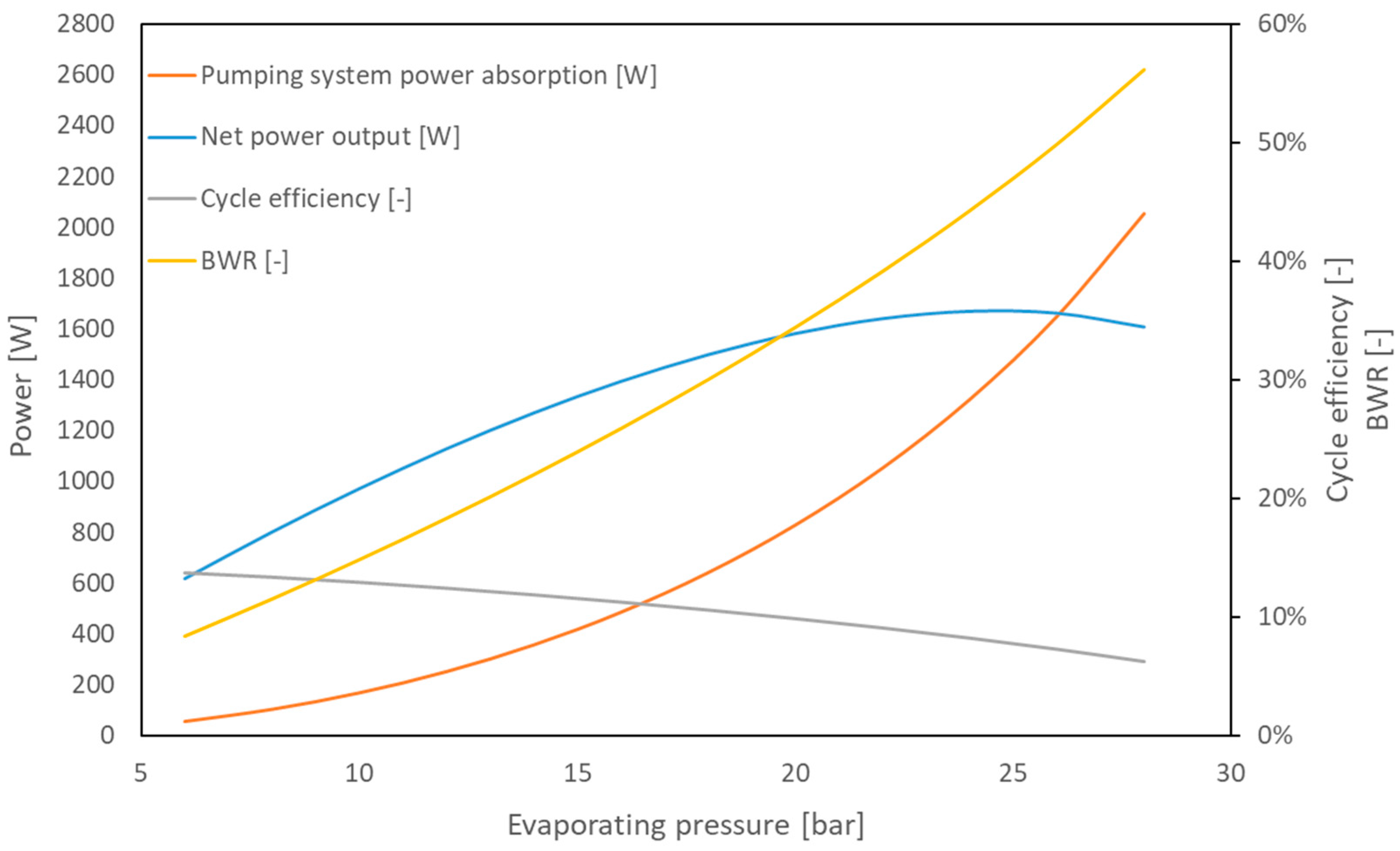
Increasing the evaporating pressure also has a consequence in the pumping work that rises as shown in
Figure 8a, and it affects the net output power up to 8%, as shown in
Figure 8b at 25 bar.
The pump power is related to the fluid flow rate that flows through the expander and the inlet–outlet pressure conditions that impose the load and the fluid specific volume. The main parameters are reported in
Figure 9: it can be noticed that the mass flow rises up to four times in the range of interest.
As illustrated before, the design working conditions could vary a lot while fixing the scroll geometry and rotational speed. In the range of interest, the best efficiency does not match with the highest net power output (
Figure 10). The thermodynamic cycle performs better under an evaporating pressure near 10 bar, but, as it can be observed in
Figure 8b, in this condition, the net power output does not reach an acceptable value as it is lower than 1.000 W.
The pump contribution becomes relevant with respect to the output power if an electrical motor and an inverter are considered. In a real case, due to the low efficiency of the pumping system, when the evaporating pressure grows up to 24 bar, the BWR could exceed 20% of the electrical power output, lowering the conversion efficiency of the system.
3.1. Definition of the Design Point and Components
Starting from the considerations outlined in the previous paragraph, the test bench is designed to fix an evaporating pressure of 18 bar as a reference value. There are different target compromises for what concerns the operating conditions and practical realization advantages.
First, an output power above 1500 W in this condition is achieved: it is a significant value in line with a possible domestic application. Furthermore, the pump power is limited, and the BWR remains under 5%.
Concerning the components that should be installed in the test rig, a maximum value of 18 bar allows operating in security, and the scroll expander is supposed to guarantee long-term durability without high mechanical and thermal stresses.
The temperature of the hot heat source is fixed to 150 °C, which is reasonable considering parabolic trough collectors as a heat source for the ORC system.
The temperature of the heat sink is fixed to 40 °C, which is compatible considering a water-cooled heat sink.
With the boundary condition described, a net electric power output of 1.500 W could be obtained with a conversion efficiency of almost 12%.
3.2. Prototype Setup
In this paragraph, the instruments, devices, and software developed and used for controlling the plant prototype and data acquisition are presented. The results are presented as a P&I scheme of the plant.
3.2.1. Sensors and Instruments
The characterization of the test rig requires the use of several instruments for monitoring the physical parameters during the operation.
Starting from the thermodynamic point of view, pressure and temperature transducers are necessary for evaluating the energy balances and the thermodynamic properties of the working fluid. The following sensors were chosen:
Thermoresistance 1/3 DIN classes are used to measure the temperature variation in the thermodynamic transformations that take place in the heat exchangers and in heat exchangers, pumps, and expanders.
Membrane pressure transducers with different full-scale values depending on the low-pressure or high-pressure side of installation are applied for measuring the pressure in various points of the circuit for calculating the compression ratio and the pressure drop in the heat exchangers.
Coriolis mass-flow metre is used to measure the mass flow of working fluid in the system; this value is necessary for the characterization of the components and working conditions in terms of heat and efficiency.
Other sensors were necessary for monitoring the electrical circuits:
One grid analyzer is used to measure current, power, and energy consumed by the circulating pump.
The output power produced by the scroll expander is delivered in electrical 3-phase alternating current; then, it is converted to DC and stabilized with a condenser. The DC circuit is closed on a variable resistance load; a Hall-effect transducer measures the current intensity, and an Agilent 34970A (Keysight Technologies, Santa Rosa, CA, USA) is used to measure the voltage, so it is easy to calculate the net electrical power output.
The Agilent 34970A is also used to measure the frequency of the alternating current generated by the scroll expander.
The signal from the oscilloscope drives an electronic rpm regulator especially developed for the application; this device is built on the Arduino® platform and is constituted basically by a potentiometer and a MOSFET switch that lets vary the equivalent resistance of the load circuit by changing the switch activation frequency.
Table 1 shows in detail the characteristics of the sensors used in the experimental campaign and all data acquisition instruments.
The performance of the data acquisition system allows for a description of the physical phenomena occurring with a satisfying accuracy. The data acquired has been analyzed with the error propagation theory that affirm the following: the measuring errors affecting the variables (
) used for the calculation of a derivative function (
f) affect the derivative function proportionally to the partial derivative of the derived function with respect to the individual starting variables, multiplied by the value of uncertainty on the starting variables (
)
For example, typical values of uncertainties for some interesting functioning parameters could be presented:
+/−1.5% on electric efficiency.
+/−1.5% on compression ratio.
+/−1.8% on isentropic effectiveness.
+/−0.2% on electric output power.
A case study and the related variables and uncertainties are presented in
Appendix A, referring to the experimental results obtained from the test bench.
3.2.2. Data Acquisition Software
The monitoring and control software was developed for the test rig application in Labview 2012
®, ambient connected with the NIST Refprop
® programme [
47] for the real-time calculation and elaboration of the thermodynamic properties of the working fluid. The software is able to show real-time thermodynamic diagrams like Temperature—Entropy and Pressure—Enthalpy of the fluid evolving in the test bench. By changing some control values on the user interface, it is also possible to vary some working parameters of the test bench as pump speed or steam generator power.
3.2.3. P&I of the System
The diagram in
Figure 11 shows the P&I of the system in which all depicted components are used in the development of the test bench. The position of the pressure, massflow and temperature sensors can be identified.
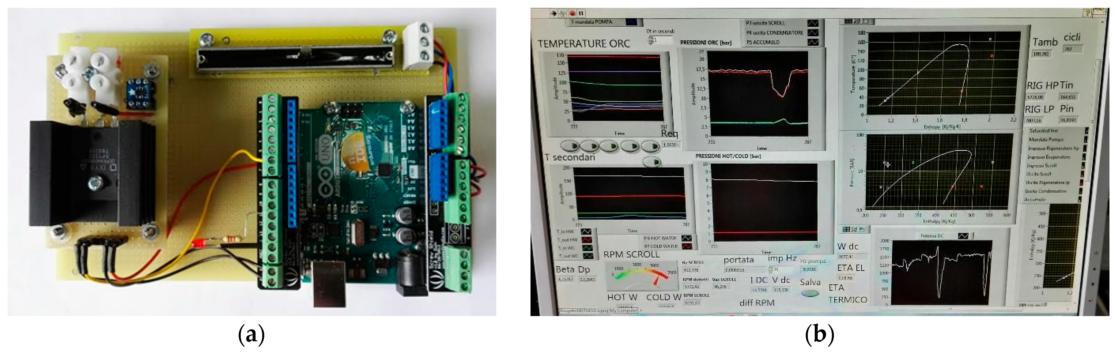
Figure 12a shows a picture of the automatic RPM regulator based on Arduino
® and specially developed for this application, and
Figure 12b is the user interface of the managing and data acquisition system developed in Labview 2012
®, in which the thermodynamic schemes (pressure—enthalpy and temperature—entropy diagrams) and other control variables are present.
3.3. Comparisons, Model Calibration, and Validations
This study of the system’s performance with the numerical model evolves through the experimental tests on the test bench, arriving at the validation of the theoretical results with the experimental data obtained.
In the comparison between the experimental results obtained and the numerical model, it is particularly interesting to compare, on the one hand, the trend of the mass flow rate in the scroll expander chosen for operation and, on the other hand, the power absorbed by the pumping system, which is decisive for the system’s performance and final useful power.
Figure 13 illustrates the relationship between the mass flow rate [g/s] and the rotational speed [RPM] of the scroll expander operating in the ORC system in the case of the experimental tests and the developed theoretical model. The blue triangular markers represent the experimental data collected under varying operating conditions, while the red curve indicates the theoretical mass flow rate, calculated as a function of scroll expander displacement and operating fluid pressures, temperatures, and densities.
The theoretical curve follows an exponential upward trend, consistent with the expectation that higher RPMs yield increased flow rates due to a greater number of expansion cycles per unit time. The experimental data generally follow the same trend, though with some dispersion likely due to real-world inefficiencies such as leakage, pressure drops, and heat losses. The comparison between measured and theoretical values provides valuable insight into the expander’s actual performance and highlights areas where system optimization may be possible.
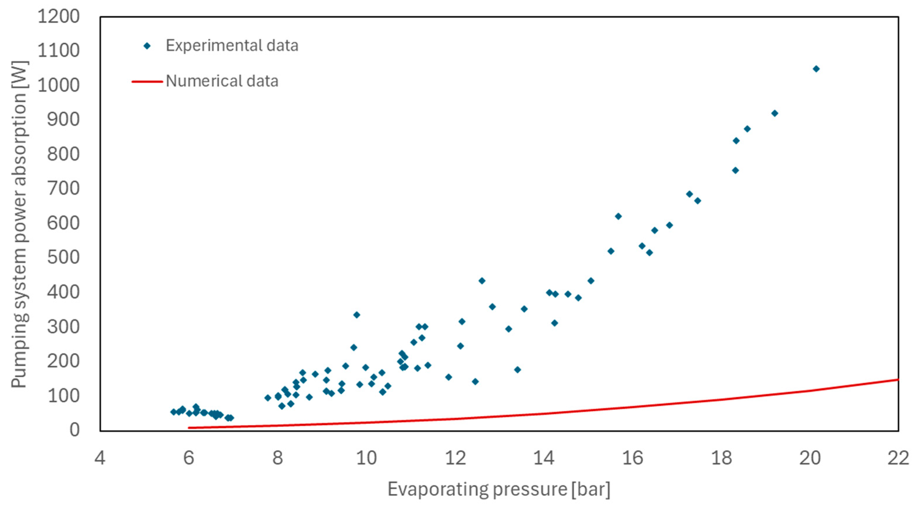
As far as the power consumption of the pumping system is concerned,
Figure 14 shows a comparison between the experimentally measured pumping power at varying evaporation pressure of the ORC system and the values predicted by the numerical model. The model estimates energy consumption based on fluid density, pressure difference, and pump displacement, assuming a nominal isentropic efficiency of 85%. As can be seen, the predicted trend significantly overestimates the actual power demand. This discrepancy suggests that the actual pumping system operates with significantly lower efficiency, a phenomenon well documented in the literature [
7,
38,
39], especially for small-scale ORC applications, where positive displacement pumps are subject to substantial mechanical and volumetric losses.
In
Figure 15, the model is refined by incorporating a more realistic isentropic efficiency of 12%, derived experimentally as a function of the compression ratio, thus calibrating the model to the actual operation of the machine and the components used in the test bench. With this correction, the numerical predictions align much more closely with the experimental data, both in terms of trend and magnitude. This increased agreement confirms the importance of taking real operating conditions into account in component-level modelling. The strong sensitivity of pumping efficiency to operating conditions, such as pressure ratio, fluid viscosity, and velocity, requires going beyond assumptions of constant efficiency. The updated model therefore reflects not only a more accurate estimate of energy consumption but also introduces a more rigorous thermodynamic framework capable of capturing degradation effects in low-efficiency operating regimes.
Figure 15 again shows the power absorption of the pumping system as a function of evaporation pressure, comparing experimental data (blue dots) with numerical data (red line). To these, a tolerance interval of ±10% was added around the numerical curve (green and blue dotted lines). The numerical curve (red) represents the average trend of the experimental data well: most of the experimental points are within ±10% of the numerical curve, confirming good accuracy of the model. For pressures below 10 bar, the experimental data are well distributed around the numerical curve, with small fluctuations, while, for pressures above 15 bar, a greater dispersion is observed, and some experimental points lie above +10%, indicating a possible increase in the experimental error or a slight underestimation of the numerical model at high pressures.
The introduction of tolerance bands helps to visualize the limits of acceptable accuracy: the numerical model is generally reliable within ±10%, but, for a critical application, it may be useful to investigate further the larger deviations at high pressures.
Finally,
Figure 16 shows the deviations between experimental and numerical data of the power absorbed by the pumping system as a function of the inlet pressure to the scroll expander: as already shown by the ±10% deviation curves in
Figure 15, a reduced deviation is indicated at pressures lower than 15 bar, showing for lower operating pressures a particular accuracy of the numeric model with respect to the real operation of the machine.
4. Conclusions
The work is focused on the development of a micro-ORC plant with a numerical analysis developed for the design of an experimental test bench and the characterization of a commercial scroll compressor as an expander.
The aim of this work was to illustrate in detail the design of the test bench, the instrumentation used, and the numerical model used in connection with the experimental tests.
The cycle configuration is a classical Rankine cycle with the addition of regeneration and the introduction of a regenerative process that increases the energetic efficiency of the system. A commercial hermetic scroll compressor is employed as an expander with HFC-245fa as the working fluid: the equipment selected for the application is a 33 cm3 scroll compressor with the geometric ratio of the suction and discharge volume equal to 4, directly connected to a brushless three-phase motor.
With the development of the numerical model, a number of boundary conditions is set, and the numerical results are expressed in the form of a sensitivity study that analyzed some important output parameters of the system. Numerical modelling shows that, by applying regeneration and fixing the expansion ratio, the isentropic enthalpic efficiency increases with increasing evaporation pressure, reaching a maximum around 15% for a pressure value around 10 bar and then decreasing, while the pump power and the output power increase with increasing evaporation pressure.
The increase in evaporation pressure leads to an increase in pumping work, and this affects net power output by up to 8% (for an evaporation pressure of 25 bar).
The design working conditions could vary a lot while fixing the scroll geometry and rotational speed, and, for this reason, the numerical model developed was supplemented with boundary conditions derived from the test bench developed. The pump contributed becomes relevant in respect to the output power if an electrical motor and an inverter are considered: in a real case, due to the low efficiency of the pumping system, when the evaporating pressure reaches 24 bar, the BWR could exceed 20% of electrical power output, lowering the conversion efficiency of the system.
The test bench is therefore designed by fixing an evaporation pressure equal to 18 bar as a reference value. First, an output power above 1500 W in this condition is achieved: it is a significant value in line with a possible domestic application with a conversion efficiency of almost 12%. Furthermore, the pump power is limited, the BWR remains under 5%, the temperature of the hot heat source is set at 150 °C, and that of the heat sink at 40 °C. With the boundary condition described, a net electric power output of 1.500 W could be obtained with a conversion efficiency of almost 12%.
This result is evidently also demonstrated in the validation of the numerical model with the experimental results: in fact, if, at first, one starts from a pump efficiency of 0.85 and the absorption curve of the pumping system as a function of evaporation pressure appears very far from the trend of the experimental results, once an actual efficiency of 0.12 resulting from the empirical relationship with the compression ratio is inserted, the two trends are consistent.
An analysis of the deviations of the experimental results from the numerical model leads to values around 5% for evaporation pressures below 10 bar. As the evaporation pressure increases, the deviation between experimental and numerical results increases.
Once the working conditions have been established at the design point, the sensors and instruments useful for collecting and analyzing experimental data are defined, highlighting the accuracy of the instrumentation and the errors related to the measurement chain. This study illustrates the control sensors and instruments used for data acquisition during operation, indicating various characteristics and accuracy for precise error analysis. The performance of the data acquisition system lets us describe the physical phenomena occurring with a satisfying accuracy, and the data acquired has been analyzed with the error propagation theory. To monitor and control the acquisition system, software in Labview 2012®, ambient connected with the NIST Refprop® programme, was developed.
The software provides real-time visualization of thermodynamic diagrams, such as Temperature–Entropy and Pressure–Enthalpy charts, illustrating the fluid behaviour within the test bench. By adjusting control parameters through the user interface, it is also possible to modify key operating conditions, such as pump speed or steam generator power.
The results of the performance of the test bench were previously illustrated in Part 1 [
29] of the work, so the entire study was developed in the first part with the experimental analysis of the performance of a commercial scroll compressor used as an expander in a micro-ORC plant and completed in the second part with an explanation of the numerical modelling and the dedicated test bench with its instrumentation used for data acquisition. The results obtained provide a complete picture of the system’s potential and criticalities, laying the foundations for future optimisations in terms of configuration, control, and improvement of the system’s overall efficiency.
The use of a commercial scroll compressor as an expander within an ORC system can represent a valid option for such applications, paying attention to the design of the system.


 ,
, 


