
Influence of Gap Blade Geometry on the Energy Performance of Low-Specific-Speed Centrifugal Pumps


Abstract
1. Introduction
1.1. Losses in Centrifugal Pumps
- n-rotational speed (rpm);
- Q-flow rate (m3/s);
- H-head (m).
1.2. Novelty Methods to Increase Efficiency of Centrifugal Pumps
1.3. Application of Splitter Blades in Rotating Machinery
1.4. Gap Blades in Impellers of Centrifugal Pumps
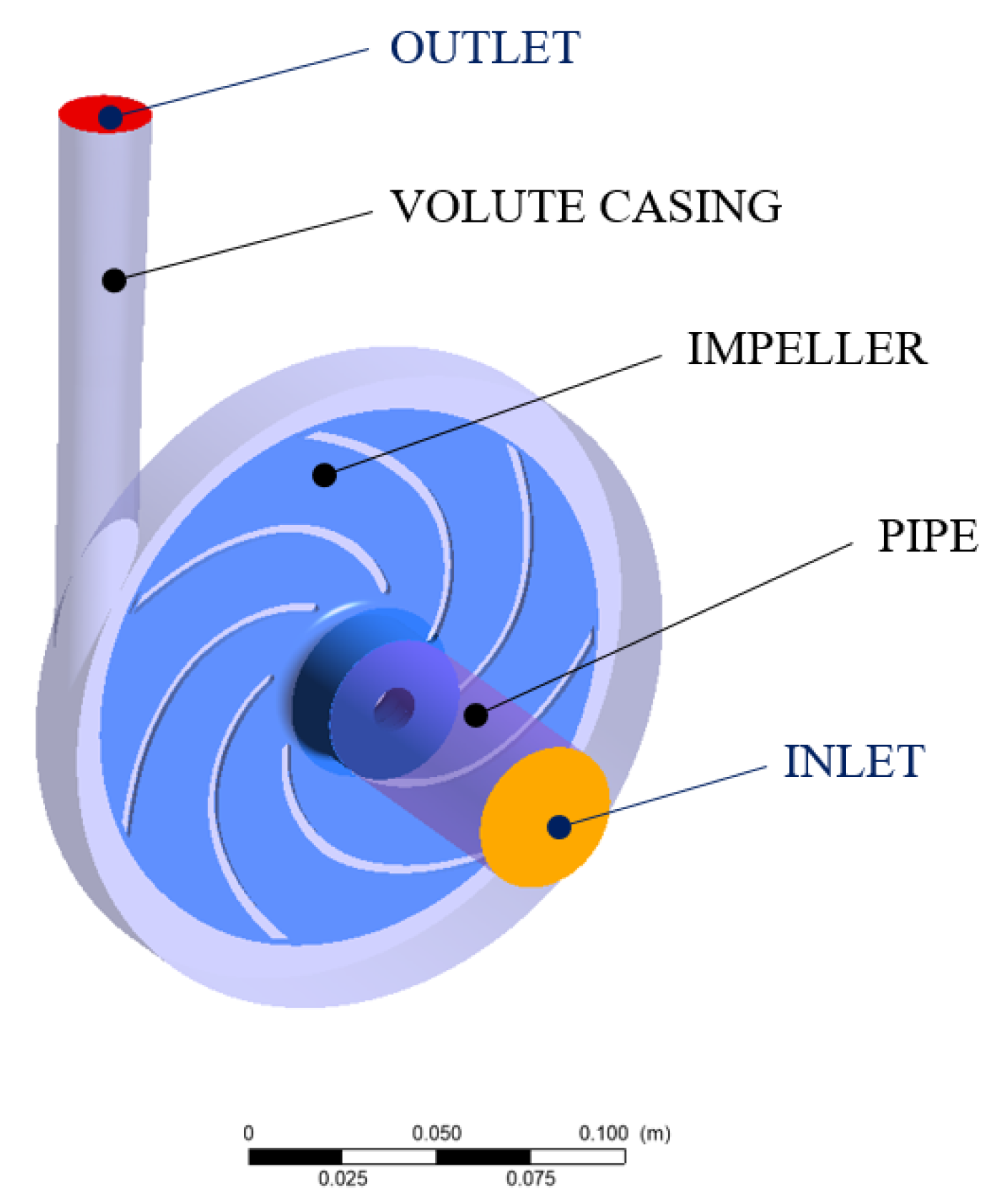
2. Research Object
3. Methodology
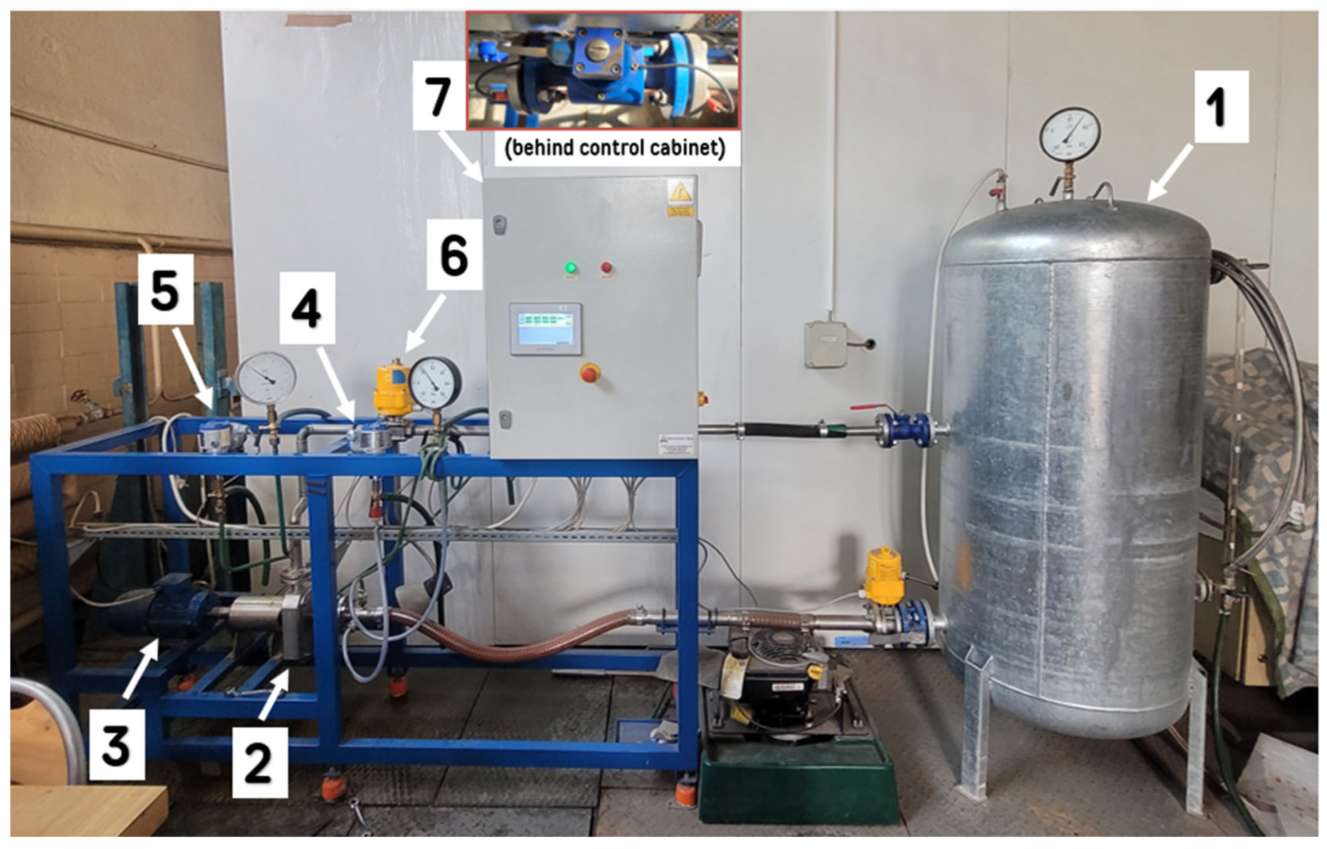
4. Experimental Studies
5. Numerical Simulations
6. Conclusions
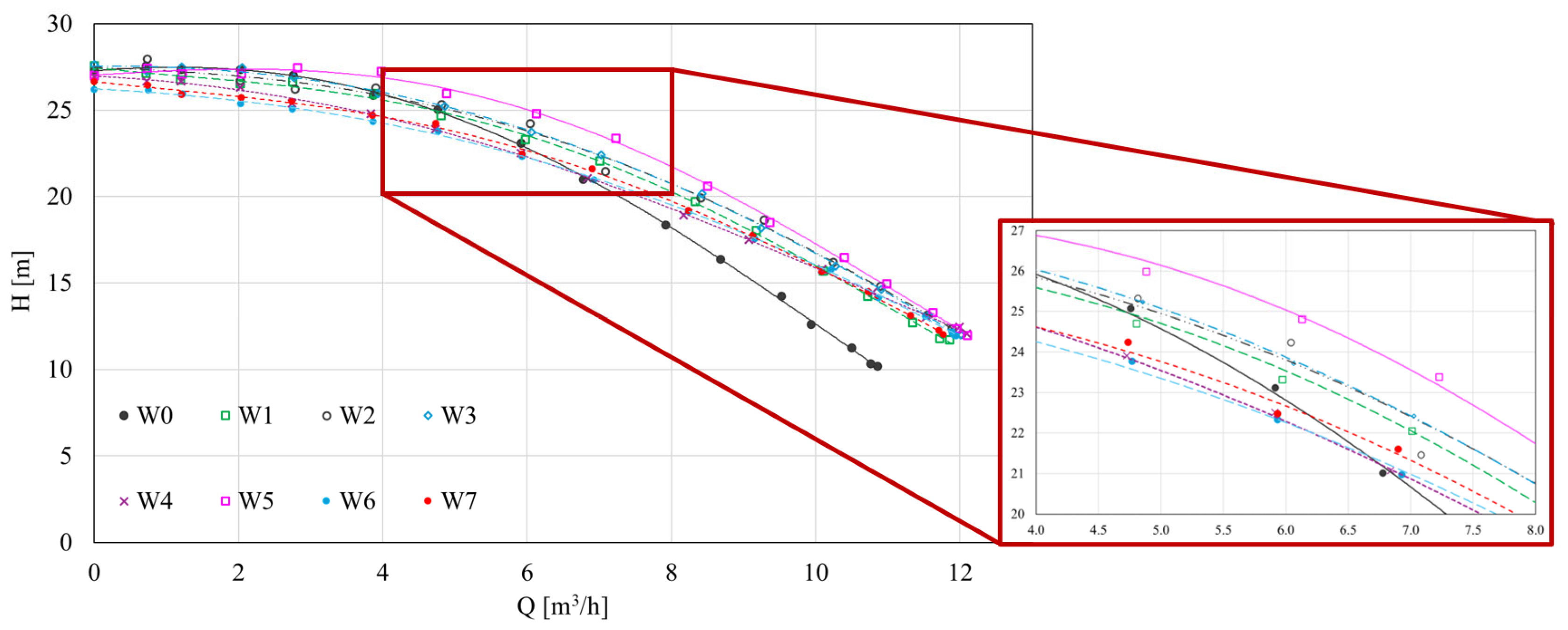
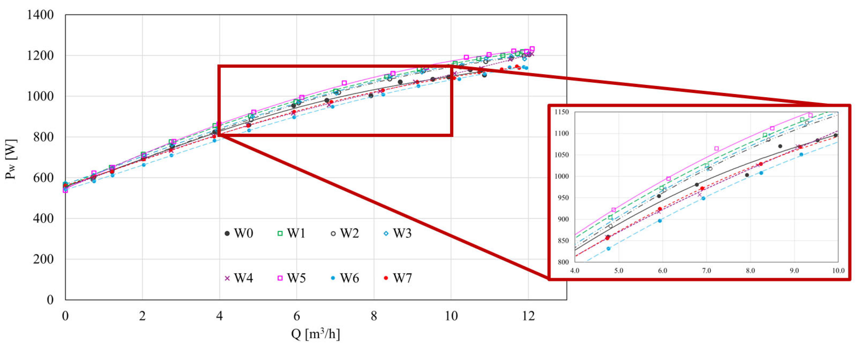
- Head measurements showed that, above 6 m3/h, most gap blade configurations provided a higher head compared to the reference impeller—Figure 2. The power at the pump shaft (Figure 4) remained largely unchanged, indicating that the efficiency gains resulted primarily from reduced internal hydraulic losses.
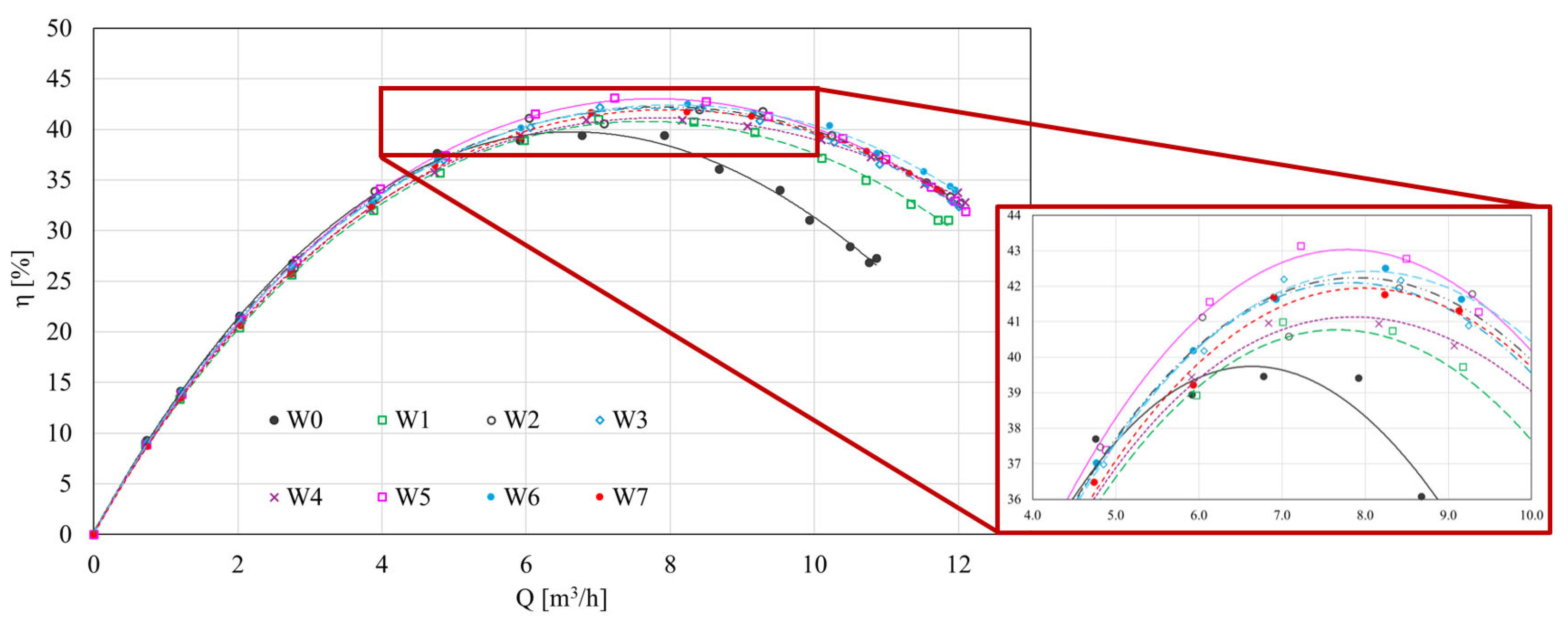
- The most significant improvement—up to approximately 4 percentage points (from 39.47% for the reference impeller to 43.33% for the gap blade impeller)—was observed for the W5 variant, where the gap was introduced by shifting a part of the main blade toward the pressure side (viewed from the inlet)—Figure 3;
- The efficiency curves η(Q)—Figure 3, for all gap blade designs, were flatter than that of W0, and the best efficiency point (BEP) was shifted toward higher flow rates. This suggests an extended range of efficient operation and more stable performance at partial load conditions;
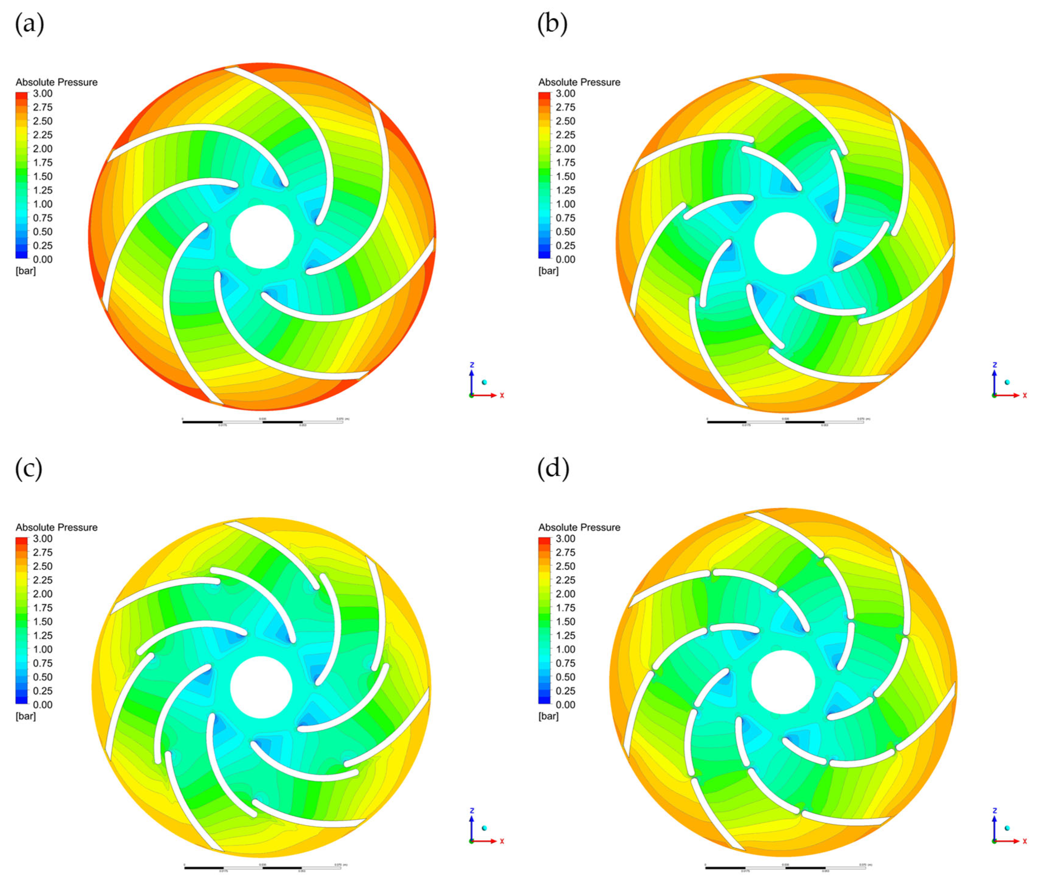
- Numerical simulations supported the experimental findings by showing that the W5 impeller generated a more uniform velocity field in the blade channels and reduced recirculation zones. Pressure contours also revealed a lower pressure gradient near the leading edge and a reduced pressure difference between the pressure and suction sides of the blade.
- Impellers W6 (gap toward the suction side) and W7 (double gap) showed less coherent flow patterns and larger low-pressure areas, which may increase the risk of cavitation and flow instabilities. These results were consistent across both experimental and CFD analyses.
- The combination of experimental testing and CFD confirmed that the W5 configuration offers the most advantageous hydraulic performance among all tested designs, thanks to improved flow guidance and pressure recovery.
Author Contributions
Funding
Data Availability Statement
Acknowledgments
Conflicts of Interest
Nomenclature
| Symbol | Name | Unit |
| b1 | impeller width at the inlet | mm |
| b2 | impeller width impeller width at the outlet | mm |
| d1 | impeller inlet diameter | mm |
| d2 | impeller outlet diameter | mm |
| Egap | gap width | mm |
| g | gravity acceleration | m/s2 |
| H | pump lifting height | m |
| Lgap | gap length | mm |
| M | total torque on the moving walls of the impeller | Nm |
| NPSH | net positive suction head | m |
| n | rotational speed | rpm |
| ns | kinematic specific speed factor, in USA units, (gpm, ft) | - |
| nq | kinematic specific speed factor, in SI units, (m3/s, m) | - |
| Pw | power input | W |
| Rgap | gap position radius | mm |
| Q | capacity | m3/h |
| T | temperature | °C |
| t | time | s |
| Greek Symbols | ||
| β | inflow angle, offset angle | ° |
| Δ | variability, difference | - |
| η | efficiency | - |
| μ | dynamic viscosity coefficient | Pa·s |
| ν | kinematic viscosity coefficient | m2/s |
| π | number, dimensionless variable | - |
| ρ | fluid density | kg/m3 |
| ω | angular velocity | rad/s |
| Subscripts | ||
| c | critical | - |
| CFD | Computational Fluid Dynamics, applies to results obtained using CFD | - |
| EXP | experimental | - |
| h | hydraulic | - |
| H2O | applies to water | - |
| i | next value | - |
| n | nominal | - |
| opt | optimal | - |
References
- The Pump Market Report; Resolute Research BV: Deventer, The Netherlands, 2017.
- Arun Shankar, V.K.; Umashankar, S.; Paramasivam, S.; Hanigovszki, N.A. Comprehensive Review on Energy Efficiency Enhancement Initiatives in Centrifugal Pumping System. Appl. Energy 2016, 181, 495–513. [Google Scholar] [CrossRef]
- Vogelesang, H. An Introduction to Energy Consumption in Pumps. World Pumps 2008, 496, 28–31. [Google Scholar] [CrossRef]
- Jędral, W. Efektywne Energetycznie Układy Pompowe; Oficyna Wydawnicza Politechniki Warszawskiej: Warszawa, Poland, 2018. [Google Scholar]
- Gülich, J.F. Centrifugal Pumps, 2nd ed.; Springer: New York, NY, USA, 2010. [Google Scholar]
- Jędral, W. Pompy Wirowe; Wydawnictwo Naukowe PWN: Warszawa, Poland, 2001. [Google Scholar]
- troskolański, T.A.; Łazarkiewicz, S.z. Pompy Wirowe; Państwowe Wydawnictwa Techniczne: Warszawa, Poland, 1973. [Google Scholar]
- Gülich, J.F. Disk Friction Losses of Closed Turbomachine Impellers. Forschung im Ingenieurwesen/Eng. Res. 2003, 68, 87–95. [Google Scholar] [CrossRef]
- Juckelandt, K.; Bleeck, S.; Wurm, F. H Analysis of Losses in Centrifugal Pumps with Low Specific Speed with Smooth and Rough Walls. In Proceedings of the 11th European Conference on Turbomachinery Fluid Dynamics & Thermodynamic, Madrid, Spain, 23–27 March 2015. [Google Scholar]
- Visser, F.C.; Brouwers, J.J.H.; Jonker, J.B. Fluid Flow in a Rotating Low-Specific-Speed Centrifugal Impeller Passage. Fluid. Dyn. Res. 1999, 24, 275–292. [Google Scholar] [CrossRef]
- Peng, G.; Hong, S.; Chang, H.; Fan, F.; Zhang, Y.; Shi, P. Numerical and Experimental Research on the Influence of Clearance Between Impeller and Cover on the Pump Performance. Mechanika 2022, 28, 67–72. [Google Scholar] [CrossRef]
- Bieganowski, M.; Skrzypacz, J.; Chomiuk, B. The Influence of the Geometry of Grooves on the Operating Parameters of the Impeller in a Centrifugal Pump with Microgrooves. Energies 2024, 17, 2807. [Google Scholar] [CrossRef]
- Sosnowski, M.; Skrzypacz, J.; Szulc, P. Wpływ ukształtowania krawędzi wylotowej wirnika na parametry energetyczne pompy. Kierunek Pompy 2024, 1/2024, 92–97. [Google Scholar]
- Gangipamula, R.; Ranjan, P.; Patil, R.S. Study on Fluid Dynamic Characteristics of a Low Specific Speed Centrifugal Pump with Emphasis on Trimming Operations. Int. J. Heat. Fluid. Flow. 2022, 95. [Google Scholar] [CrossRef]
- Skrzypacz, J.; Szulc, P.; Chomiuk, B.; Bieganowski, M.; Nycz, A. Strukturyzacja Powierzchni Zewnętrznych Wirnika. Kierunek Pompy 2025, 1/2025, 88–91. [Google Scholar]
- Qiu, X.; Dang, T. 3D Inverse Method for Turbomachine Blading with Splitter Blades. In Proceedings of the ASME Turbo Expo 2000: Power for Land, Sea, and Air, 2000-GT-0526, Munich, Germany, 8–11 May 2000. [Google Scholar]
- Pham, K.-Q.; Le, X.-T.; Dinh, C.-T. Effects of Stator Splitter Blades on Aerodynamic Performance of a Single-Stage Transonic Axial Compressor. J. Mech. Eng. Sci. 2020, 14, 7369–7378. [Google Scholar] [CrossRef]
- Heo, M.W.; Kim, J.H.; Kim, K.Y. Design Optimization of a Centrifugal Fan with Splitter Blades. Int. J. Turbo Jet Engines 2015, 32, 143–154. [Google Scholar] [CrossRef]
- Jang, C.M.; Choi, K.R.; Yang, S.H. Performance Analysis of a Centrifugal Fan with Splitters. Trans. Korean Soc. Mech. Eng. B 2011, 35, 1067–1073. [Google Scholar] [CrossRef]
- Wang, Z.; Yang, H.; Xia, X.; Li, X.; Zuo, Q.; Xie, B.; Chen, W. Optimization of a Radial Inflow Turbine Rotor with Splitter Blades Based on Entropy Production Theory and Artificial Neural Network. Appl. Therm. Eng. 2024, 252, 123759. [Google Scholar] [CrossRef]
- Zhao, T.; Jiang, Z.; Mo, G.; Wang, G.J.; Gao, J. Control of Separation Flows of Turbine-Blade-Tip Turbines by Splitter Blades. Proc. Inst. Mech. Eng. Part A J. Power Energy 2024, 238, 985–998. [Google Scholar] [CrossRef]
- Chen, J.; Qu, H.; Li, P.; Li, Y.; Xie, Y.; Zhang, D. Numerical Study on Flow Separation Control for High-Lift Low-Pressure Turbine Split Blade. In Proceedings of the ASME 2013 Fluids Engineering Division Summer Meeting, Incline Village, NV, USA, 7–11 July 2013. proceeding paper: 13 December 2013. [Google Scholar] [CrossRef]
- Moshfeghi, M.; Hur, N. Power Generation Enhancement in a Horizontal Axis Wind Turbine Blade Using Split Blades. J. Wind. Eng. Ind. Aerodyn. 2020, 206, 104352. [Google Scholar] [CrossRef]
- Jia, Y.; Wei, X.; Wang, Q.; Cui, J.; Li, F. Experimental Study of the Effect of Splitter Blades on the Performance Characteristics of Francis Turbines. Energies 2019, 12, 1676. [Google Scholar] [CrossRef]
- Yang, S.; Kong, F.; Fu, J.; Xue, L. Numerical Research on Effects of Splitter Blades to the Influence of Pump as Turbine. Int. J. Rotating Mach. 2012, 2012, 1542–3034. [Google Scholar] [CrossRef]
- Bezdíček, J.; Chabannes, L.; Štefan, D. Effect of Splitter Blades on Turbine Mode of Low Specific Speed Pump. EPJ Web Conf. 2024, 299, 01003. [Google Scholar] [CrossRef]
- Xiao, W.; Chen, L.; Ren, S.; Yan, B.; Liu, Z.; Xiao, Y. Analysis of Pressure Fluctuation of a Pump-Turbine with Splitter Blades on Small Opening in Turbine Mode. Energies 2024, 17, 2967. [Google Scholar] [CrossRef]
- Wang, H.; Long, B.; Wang, C.; Han, C.; Li, L. Effects of the Impeller Blade with a Slot Structure on the Centrifugal Pump Performance. Energies 2020, 13, 1628. [Google Scholar] [CrossRef]
- Ke, Q.; Tang, L. Performance Optimization of Slotted Blades for Low-Specific Speed Centrifugal Pumps. Adv. Civil. Eng. 2023, 2023, 1–16. [Google Scholar] [CrossRef]
- Hongxun, C.; Weiwei, L.; Wen, J.; Peiru, W. Impellers of Low Specific Speed Centrifugal Pump Based on the Draughting Technology. IOP Conf. Ser. Earth Environ. Sci. 2010, 12, 012018. [Google Scholar] [CrossRef]
- Chen, H.; He, J.; Liu, C. Design and Experiment of the Centrifugal Pump Impellers with Twisted Inlet Vice Blades. J. Hydrodyn. 2017, 29, 1085–1088. [Google Scholar] [CrossRef]
- Wei, Y.; Yang, Y.; Zhou, L.; Jiang, L.; Shi, W.; Huang, G. Influence of Impeller Gap Drainage Width on the Performance of Low Specific Speed Centrifugal Pump. J. Mar. Sci. Eng. 2021, 9, 106. [Google Scholar] [CrossRef]
- Zhu, B.; Chen, H.X. Cavitating Suppression of Low Specific Speed Centrifugal Pump with Gap Drainage Blades. J. Hydrodyn. 2012, 24, 729–736. [Google Scholar] [CrossRef]
- Montgomery, D.C. Design and Analysis of Experiments, 8th ed.; John Wiley & Sons, Inc: Hoboken, NJ, USA, 2013; ISBN 9781118146927. [Google Scholar]
- EN ISO 9906:2012; Rotodynamic Pumps—Hydraulic Performance, Acceptance Tests—Grades 1, 2 and 3. International Organization for Standardization: Geneva, Switzerland, 2012.
- Skrzypacz, J. Numerical Modelling of Flow Phenomena in a Pump with a Multi-Piped Impeller. Chem. Eng. Process. Process Intensif. 2014, 75, 58–66. [Google Scholar] [CrossRef]
- Nycz, A.; Szulc, P.; Skrzypacz, J. Identyfikacja Zjawisk Przepływowych w Rurze Ssącej Średniobieżnej Turbiny Wodnej z Wykorzystaniem CFD. Rynek Energii 2024, 4, 64–73. [Google Scholar]


| No. | Application | Description | Source |
|---|---|---|---|
| 1. | Axial stator of a compressor | A reduction in Mach number was achieved from 1.38 to 1.22, along with a decrease in total pressure losses from 1.8% to 1.3%. The shock wave and excessive angle of incidence on the splitter blade were eliminated. An analysis of different load distribution ratios (for example, 67/33%) showed the influence of this parameter on pressure distribution and flow improvement. | [16] |
| 2. | Axial compressor | The application of longer splitter blades in the stator of a single-stage transonic axial compressor reduced the total pressure loss coefficient by 7.2% and improved the flow angle distribution downstream of the rotor. The beneficial effect of the modification was confirmed throughout the compressor load range. | [17] |
| 3. | Radial fan | An increase in efficiency by 3.81% and 3.82% and an increase in total pressure by 69.59 Pa and 63.7 Pa were obtained. CFD calculations using the RANS model confirmed improvements in pressure distribution and reduction of low-velocity zones. | [18] |
| 4. | Radial fan | The best results were obtained with a splitter blade length corresponding to 60% of the suction side; the total pressure increased by 18%, and efficiency improved by 4%. Backflow was reduced, and pressure distribution was improved, particularly at higher flow rates. | [19] |
| 5. | ORC turbine | An efficiency improvement of 4.65% and a reduction in entropy production in the rotor of 33.3% and 44.1% in the entire turbine were achieved. CFD calculations were experimentally validated with an error margin of up to 2.47%. | [20] |
| 6. | Gas turbine with turbine-blade-tip | The addition of splitter blades to blade-tip gas turbines reduced flow separation and improved turbine efficiency. Shortening the length of the splitter blade chord reduced the effectiveness of this improvement. | [21] |
| 7. | High-lift-type LPT (low pressure turbine) | In a high-lift, low-pressure turbine, the use of splitter blades at Reynolds numbers Re ≥ 50,000 limited flow separation and shifted the reattachment point downstream. At Re = 25,000, the effect was minimal. This solution improved aerodynamic performance without increasing the number of blades. | [22] |
| 8. | Wind turbine | In a HAWT wind turbine with S809 blades, for a tip-speed ratio (TSR) below 3.5, all blade configurations augmented with gaps generated more power compared to the reference without a gap. The best result was obtained for the full-gap variant (SEG.ALL), with a 47.7% increase in power at 20 m/s. The improvement was attributed to the reduction in flow separation, whose effectiveness depended on the location of the gap and the flow conditions. | [23] |
| 9. | Water turbine | In a Francis turbine (nq = 141.7, H = 202 m), under high head conditions (243 m), the efficiency increased by 2%, while under low head conditions, the efficiency decreased. Cavitation on the suction side was reduced, and pressure fluctuations decreased by 58.1%. The use of splitter blades improved flow conditions and operational stability outside the nominal operating point. | [24] |
| 10. | PaT (pump as turbine) | The application of splitter blades in a pump operating in turbine mode (PaT) increased efficiency from 65.77% to 69.19% and reduced the required head from 40.69 to 36.80 m. The amplitude of pressure pulsations decreased by up to 58.9%. The numerical results were experimentally confirmed. | [25] |
| 11. | PaT | The influence of the blades of the splitter on the operation of a centrifugal pump (ns = 32 min−1) in turbine mode was analysed. Three impeller configurations were studied. The variant with one pair of splitter blades yielded the highest efficiency gain, in the order of tenths of a percent, and shifted the best efficiency point (BEP) towards lower specific speeds. The splitter blades dampened the suction side vortices but generated additional vortices. The side gap flows reduced the torque. FFT analysis revealed the presence of additional frequencies associated with the splitter blades. | [26] |
| 12. | PaT | CFD calculations (using the k-ε model) showed that at nominal head conditions (1.0 H), efficiency increased from 89.6% to 93% after applying the splitter blades. Under reduced head conditions (0.9 H), efficiency decreased to 82.9%. The addition of splitter blades reduced backflow regions, limited pressure fluctuations, and improved flow symmetry. This application was related to a 300 MW energy storage PaT unit. | [27] |
| No. | Impeller Code | Description | Geometric Parameters | |||
|---|---|---|---|---|---|---|
| R1gap | R2gap | Lgap | Egap | |||
| 0. | W0 | Continuous blade | - | - | - | - |
| 1. | W1 | Gap blade | 49.4 | 52.3 | 2.9 | - |
| 2. | W2 | Gap blade | 49.7 | 50.9 | 1.2 | - |
| 3. | W3 | Gap blade | 46.9 | 50.4 | 3.5 | 4.7 |
| 4. | W4 | Gap blade | 54.9 | 50.4 | 4.5 | 4.8 |
| 5. | W5 | Gap blade | 46.9 | 47.9 | 1.0 | 4.9 |
| 6. | W6 | Gap blade | 57.3 | 50.4 | 6.9 | 4.7 |
| 7. | W7 | Gap blade | 39.5/40.3 | 56.8/57.5 | 0.8/0.7 | - |
| Impeller | Explanatory Drawing | Photo |
|---|---|---|
| W0 | 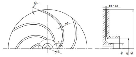 | 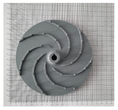 |
| W1 | 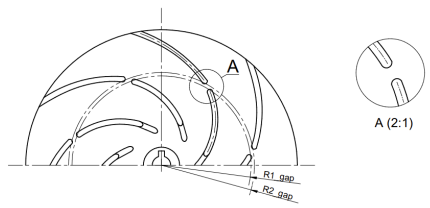 | 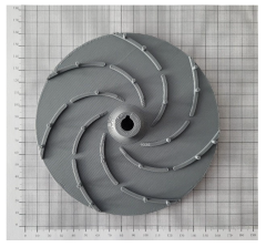 |
| W2 | 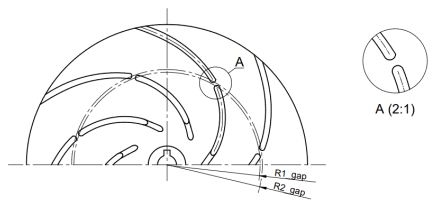 | 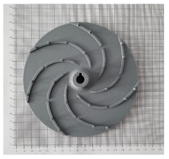 |
| W3 |  | 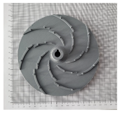 |
| W4 | 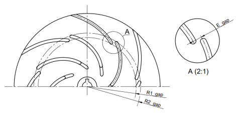 | 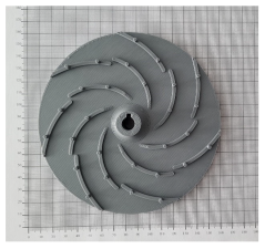 |
| W5 |  |  |
| W6 | 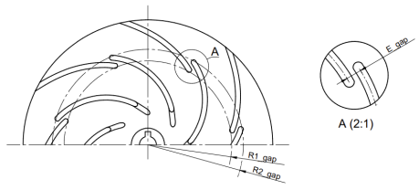 | 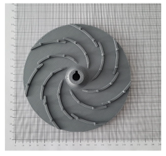 |
| W7 | 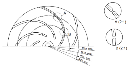 | 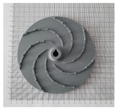 |
| No. | Measuring Instrument | Measurement Range | Accuracy Class |
|---|---|---|---|
| 1. | Electromagnetic flowmeter Arkon MAGS1-ST DN25 PN 40 (Arkon Flow Systems, Brno, Czech Republic) | 0.18–17.67 m3/h (0.1–10 m/s) | 0.2% |
| 2. | Pressure gauge on pump suction FUJI FKP 01 (Fuji Electric, Clermont-Ferrand, France) | (−0.7)–(+0.5) bar | 0.1% |
| 3. | Pressure gauge on the pump discharge FUJI FKP 03 (Fuji Electric, Clermont-Ferrand, France) | 0–30 bar | 0.1% |
| 4. | Power transducer METROL PP73 (METROL, Zielona Gora, Poland) | 0–3000 W | 0.3% |
| 5. | Temperature transmitter FLEXTOP (SIMEX, Gdansk, Poland) | 0–50 °C | ±0.9 °C |
| Impeller | Number of Elements | Average Quality | Average Skewness | Aspect Ratio (Average) |
|---|---|---|---|---|
| W0 | 40,433,678 | 0.62324 | 0.19244 | 4.7541 |
| W5 | 39,051,245 | 0.61305 | 0.19570 | 4.8462 |
| W6 | 39,454,588 | 0.64217 | 0.19510 | 4.5086 |
| W7 | 40,195,105 | 0.63177 | 0.19258 | 4.6425 |
Disclaimer/Publisher’s Note: The statements, opinions and data contained in all publications are solely those of the individual author(s) and contributor(s) and not of MDPI and/or the editor(s). MDPI and/or the editor(s) disclaim responsibility for any injury to people or property resulting from any ideas, methods, instructions or products referred to in the content. |
© 2025 by the authors. Licensee MDPI, Basel, Switzerland. This article is an open access article distributed under the terms and conditions of the Creative Commons Attribution (CC BY) license (https://creativecommons.org/licenses/by/4.0/).
Share and Cite
Nycz, A.; Skrzypacz, J.; Szulc, P. Influence of Gap Blade Geometry on the Energy Performance of Low-Specific-Speed Centrifugal Pumps. Energies 2025, 18, 2867. https://doi.org/10.3390/en18112867
Nycz A, Skrzypacz J, Szulc P. Influence of Gap Blade Geometry on the Energy Performance of Low-Specific-Speed Centrifugal Pumps. Energies. 2025; 18(11):2867. https://doi.org/10.3390/en18112867
Chicago/Turabian StyleNycz, Aneta, Janusz Skrzypacz, and Przemysław Szulc. 2025. "Influence of Gap Blade Geometry on the Energy Performance of Low-Specific-Speed Centrifugal Pumps" Energies 18, no. 11: 2867. https://doi.org/10.3390/en18112867
APA StyleNycz, A., Skrzypacz, J., & Szulc, P. (2025). Influence of Gap Blade Geometry on the Energy Performance of Low-Specific-Speed Centrifugal Pumps. Energies, 18(11), 2867. https://doi.org/10.3390/en18112867