Article

Atmospheric Turbulence Effects on Wind Turbine Wakes over Two-Dimensional Hill: A Wind Tunnel Study

by
Bowen Yan
1,
Shuangchen Tang
1,
Meng Yu
1,
Guowei Qian
2,3,* and
Yao Chen
1
1
Chongqing Key Laboratory of Wind Engineering and Wind Resource Utilization, School of Civil Engineering, Chongqing University, Chongqing 400045, China
2
Southern Marine Science and Engineering Guangdong Laboratory (Zhuhai), School of Ocean Engineering and Technology, Sun Yat-Sen University, Zhuhai 519082, China
3
Key Laboratory of Comprehensive Observation of Polar Environment, Sun Yat-Sen University, Ministry of Education, Zhuhai 519082, China
*
Author to whom correspondence should be addressed.
Energies 2025, 18(11), 2865; https://doi.org/10.3390/en18112865
Submission received: 31 March 2025 / Revised: 21 May 2025 / Accepted: 28 May 2025 / Published: 30 May 2025
(This article belongs to the Special Issue Wind Turbine Wakes and Wind Farms)

Abstract

The wake behavior of wind turbines in complex terrain is influenced by the combined effects of atmospheric turbulence and terrain features, which brings challenges to wind farm power production and safety. Despite extensive studies, there remains a gap in understanding the combined impact of turbulent inflows and terrain slopes on turbine wake behaviors. To address this, the current study conducted systematic wind tunnel experiments, using scaled wind turbines and terrain models featured both gentle and steep slopes. In the experiments, different turbulent inflows were generated and the wake characteristics of turbines located at different locations were analyzed. The results demonstrated that higher turbulence intensity accelerates wake recovery, and that steep slopes introduce distinctive wake patterns, including multi-peak added turbulence intensity profiles. Moreover, turbines on hilltops exhibited a more rapid wake recovery compared to those positioned in front of hills, a phenomenon attributed to the influence of adverse pressure gradients. This study provides pivotal experimental insights into the evolution laws of wind turbine wake over terrains under different turbulent inflow conditions, which are instrumental in wind turbine siting in complex terrains.

1. Introduction

As the wind energy industry rapidly expands, developers are increasingly situating wind turbines in complex terrain. The wind farm siting over complex terrain needs an accurate prediction of wind turbine wakes since they introduce decreased power generation and increased fatigue loading [1,2,3]. However, terrain-induced flow patterns, including flow acceleration, separation, and reattachment, make the wind turbine wake behaviors more complicated, compared to that over flat terrain [4,5,6]. Consequently, it is essential to precisely describe the wake characteristics under different turbulent inflow and turbine positions over hill.
Wind turbine wakes in complex terrains have been extensively studied by field measurements, numerical simulations, and wind tunnel experiments. Field measurements can provide valuable insights into real-world wake behavior via devices such as LiDAR [7,8,9], SCADA [10], and anemometers [11]. However, their application is challenging due to the unpredictable variations in wind characteristics, which fluctuate with diurnal cycles and seasons. These variations make field data analysis more complex. Also, the high-cost installation limits the feasibility of conducting extensive measurements in diverse locations. Numerical simulations, including LES [12,13,14] and RANS [15,16,17] can provide a detailed flow information to study wake behaviors under specified conditions. However, they depend heavily on high-precision models and require validation to ensure accuracy and reliability. Consequently, wind tunnel tests are often utilized to investigate the wake characteristics, and data obtained by these are normally considered to be more reliable. Over the past two decades, three representative types of terrain models, including sinusoidal hills [12,18,19,20], escarpments [21,22] and Gaussian hills [23,24], were mainly used in wind tunnel studies on wind turbine wakes in complex terrains. Howard et al. [18] installed a wind turbine at six rotor diameters downstream of an isolated 3D sinusoidal hill and measured the wake flow using PIV. Their results showed that the hill enhanced the turbulence levels in the inflow for wind turbine, promoting stronger turbulence mixing and faster wake recovery. A similar phenomenon was also observed by Yang et al. [12]. Later, Howard et al. [19] investigated the wake behavior of a wind turbine under different inflow conditions, including in the free stream turbulent boundary layer, in the wake of an upstream turbine, and in the wake of a 3D hill wake. They found that both the upstream turbine and hill reduced the power production of the downstream turbine. However, Hyvärinen and Segalini [20] installed two turbines in a streamwise direction on the top of periodic sinusoidal hills to measure the wake flow. They found that the presence of hilly terrain accelerated wake recovery behind the upstream turbine, resulting in higher power coefficients for the downstream turbine. Lange et al. [21] and Nanos et al. [22] placed a turbine near an escarpment to investigate the influence of the escarpment edge on turbine performance, and they observed that sharp edge of escarpment would reduce the wind turbine power due to the lower incoming wind speed in the flow separation region, as compared with that of rounded edges. More recently, Tian et al. [23] performed wind tunnel experiments to investigate the wakes of wind turbines positioned at various locations relative to a 2D Gaussian hill model (steep and gentle slopes), including in front of, on, and behind the hilltop. Their findings revealed that the wake of an upstream turbine located on the top of gentle hill had a more significant influence on downstream turbines compared to that on the top of steep hill. Chen et al. [24] examined the wake behavior of a wind turbine installed at various locations on 2D hills with gentle and steep slopes. They found that the wake of a wind turbine sited at the hilltop was more significantly influenced by the terrain than that positioned either in front of or behind the hill.
Although a lot of progress has been made in wind tunnel studies on wind turbine wakes in complex terrain, the effect of turbulent inflow is rarely discussed. However, natural wind conditions are turbulent and influence the flow of turbine wakes over complex terrain, which consequently impacts power generation and fatigue load. Uchida [25] employed LES to investigate the impact of various inflow shears on wind turbine wake characteristics over flat terrain. Despite differences in inflow shear types, the velocity deficit at the wind turbine hub center exhibited nearly identical patterns. Similarly, Wu et al. [26] utilized LES to examine the impact of different turbulent boundary layer inflows on wind farms, finding that a higher inflow turbulence level accelerated wake recovery and improved power generation. The acceleration of wake recovery for the wind turbine due to the higher inflow turbulence level was also observed by Wu and Porté-Agel [27] and Vahidi and Porté-Agel [28]. Barthelmie et al. [29,30] employed CFD to study the influence of turbulent inflow on wind turbine wakes in complex terrains by placing a wind turbine on the hilltop of Gaussian hill. They found that a higher turbulence intensity led to faster flow recovery over longer distances. Despite these findings, a significant gap exists in comprehensive and systematic experimental studies examining the effects of different turbulent inflow and turbine positions over hill.
This paper addresses the above mentioned gap by conducting a systematic wind tunnel study, in which different turbulent inflows are generated to investigate the wake behavior of turbines located at different positions and terrain slopes. The results contribute to a deeper understanding of the combined effect of turbulent inflow and terrain on turbine wake behaviors and can provide valuable experimental data for validating numerical models. The remaining structure of this paper is as follows: Section 2 introduces the wind tunnel, measurement setup, wind turbine model, and the terrain model. The results and discussion are presented in Section 3, and finally, Section 4 provides the conclusions.

2. Experimental Setup
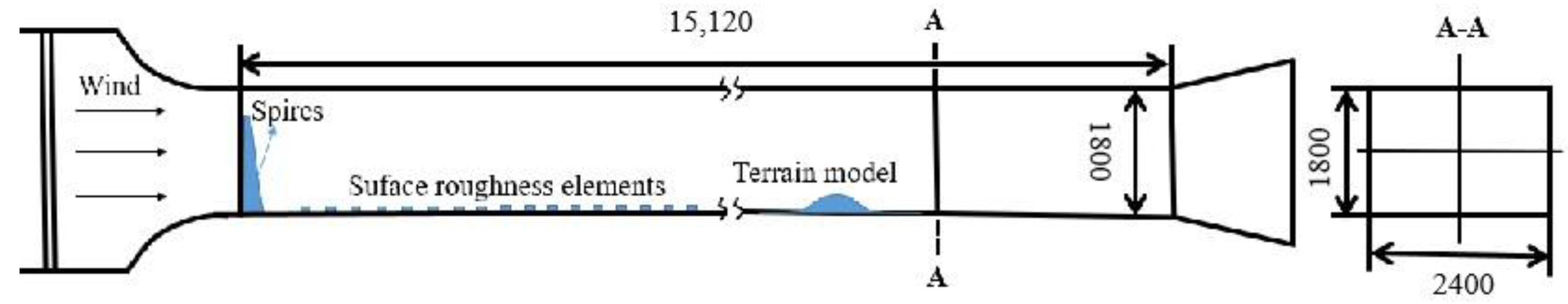
The structure of this section is as follows. Section 2.1 describes the wind tunnel configuration, while Section 2.2 and Section 2.3 outline the wind turbine and terrain models, respectively. Emphasis is given to the wake dynamics at different hill positions and slopes under different turbulent intensity. Section 2.4 then proceeds with the examination of wake data, focusing on velocity and turbulence intensity measurements.

2.1. Wind Tunnel

The study was conducted in the open-type wind tunnel laboratory within the School of Civil Engineering at Chongqing University. The wind tunnel, depicted in Figure 1, includes a test section sized at 2.4 m (width) × 1.8 m (height) × 15.1 m (length), with a peak wind velocity of 35 m/s. Turbulent inflow conditions were generated using passive devices, including baffles, spires, and roughness cells, to achieve three distinct turbulence intensity levels, as demonstrated in Figure 2.

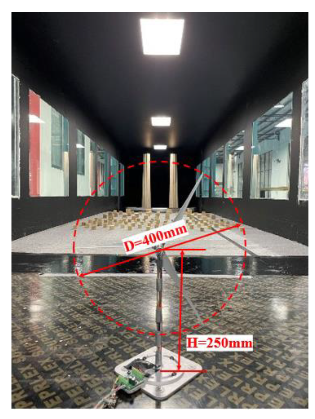
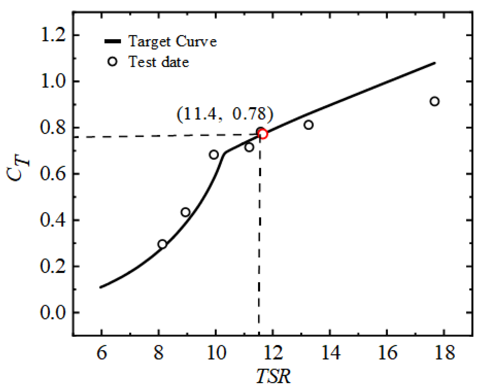
2.2. Wind Turbine Model

This investigation utilized a scaled three-blade horizontal-axis turbine model scaled to 400 mm rotor diameter (D) and positioned at 250 mm hub height (H). This model is a 1:400 scale replica of a 3.6 MW wind turbine. Further details on the design process are available in references [31,32], and the model is illustrated in Figure 3.
The thrust coefficient, which plays a critical role in determining wake distribution, is expressed as follows:
C T = T / ( 0.5 ρ U 2 A )
The thrust coefficient calculation involves several key parameters: rotor thrust force (T), atmospheric density (ρ), swept area of blades (A), and undisturbed wind velocity at hub elevation (U). To ensure dynamic similarity with full-scale turbines, the scaled model’s aerodynamic characteristics were carefully optimized through blade profile adjustments. Figure 4 demonstrates the experimentally obtained thrust coefficient variation with tip speed ratio (TSR) during flat-terrain testing. The tip speed ratio (λ) is defined as the ratio between the tangential speed of the blade tip (ωR) and the undisturbed wind speed at hub elevation ( U ), expressed as follows:
λ = ω R / U
where ω is the rotor’s angular velocity and R is the rotor radius. In all experimental cases, the wind turbine was operated at a fixed tip speed ratio (TSR) of 11.4 to maintain a thrust coefficient of 0.78 (as marked in Figure 4). This operating condition was achieved through precise servo motor control, where the rotor’s angular velocity was continuously adjusted to maintain the target TSR relative to the measured incoming wind velocity at hub height.

2.3. Terrain Models

Figure 5 shows the two terrain models investigated in this study. The geometric configurations of the two-dimensional terrain models are defined by the following mathematical expressions:
Z = H h i l l × e [ x / L 2 l n 2 ]
where Hhill corresponds to the maximum elevation of the topographic feature, while L represents the characteristic horizontal dimension measured in the direction of flow between the height of the hill from Hhill/2 to Hhill, representing the distance from the summit to the base of the hill. The terrain models have a height of 250 mm, equal to the hub height H of the wind turbine model. The slope of the terrain is defined as s = Hhill/(2L), with one model characterized by two slope parameters: s = 0.25 (gentle) and s = 0.5 (steep). The wind turbine is placed at two representative positions, including in front of the hill (x = −5D) and hilltop (x = 0D). Flow field data were collected in the streamwise (X) and vertical (Z) dimensions along the turbine’s central plane.

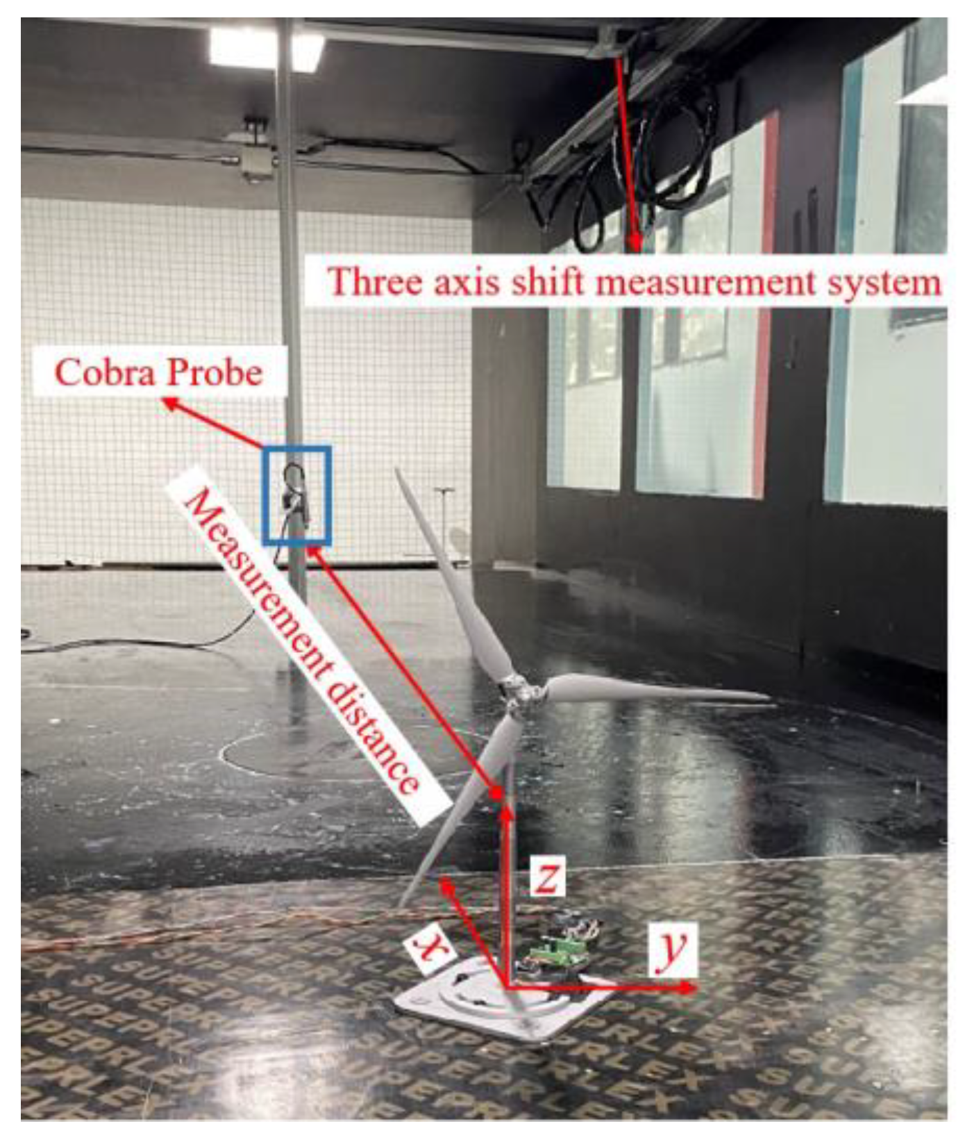
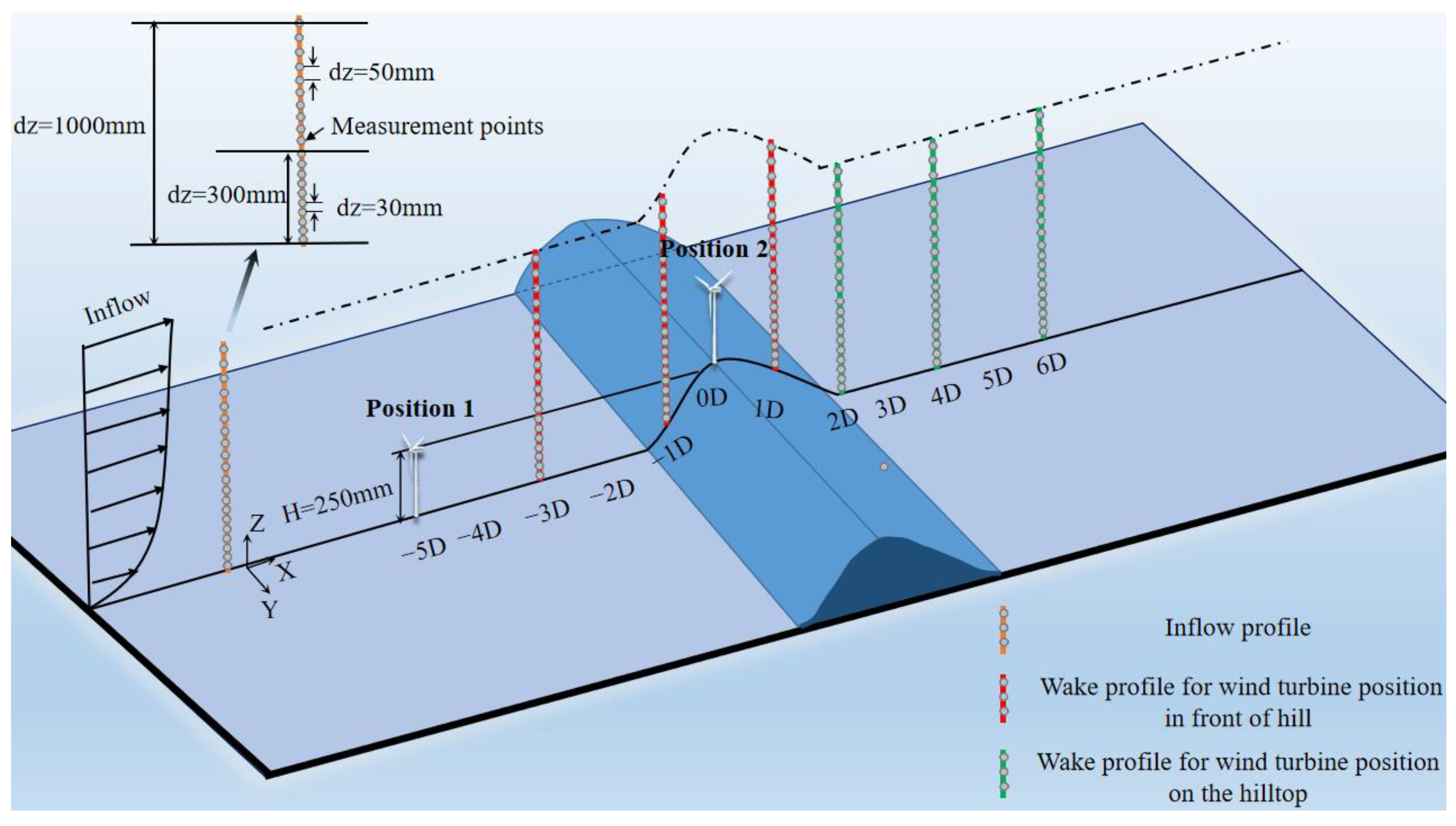
2.4. Measurement Setup

The turbulence in the far wake regions at 2D, 4D, and 6D downstream of the wind turbine model was measured using a TFI Cobra Probe anemometry system mounted on a three-dimensional traversing mechanism in the wind tunnel. Velocity measurements were obtained using a gold-coated tungsten wire sensor (∅4.0 μm) with 200 kHz bandwidth. The experimental uncertainty for velocity quantification was bounded by ±0.5 m/s. Data acquisition parameters included the following: 1000 Hz sampling frequency and 60 s observation windows per measurement location. The overall experimental arrangement is shown in Figure 6, where the x-axis represents the downwind direction, the y-axis represents the spanwise direction, and the z-axis represents the vertical direction.
The Cobra Probe allowed for the instantaneous measurement of all three velocity vector components. Streamwise velocity data were collected along a vertical profile ranging from z = 30–1000 mm, with incrementally increasing sampling intervals (Δz = 30 mm near wall, Δz = 50 mm upper region), as illustrated in Figure 7. The geometric progression of measurement points ensures comprehensive wake characterization and high-resolution data acquisition.

3. Results and Discussion

In this section, the experimental data are systematically analyzed to investigate the wake flow characteristic variations resulting from slope geometry and turbine positional parameters relative to the hill under different turbulent inflow conditions. The section is structured as follows: Section 3.1 details the incoming flow, and Section 3.2 and Section 3.3 discuss the wake characteristics of the wind turbine at different locations over different terrain models.

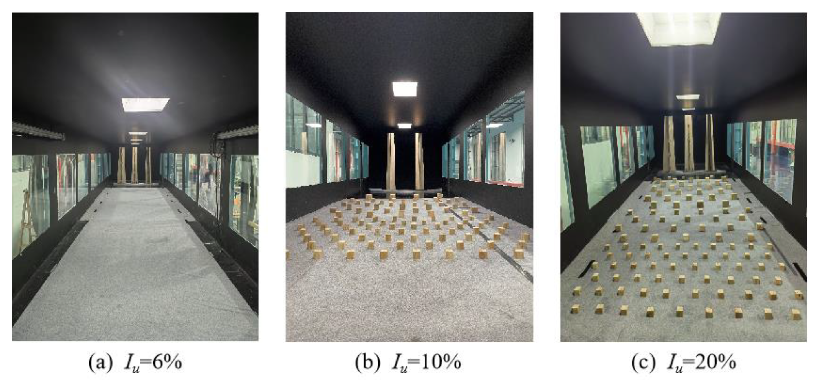
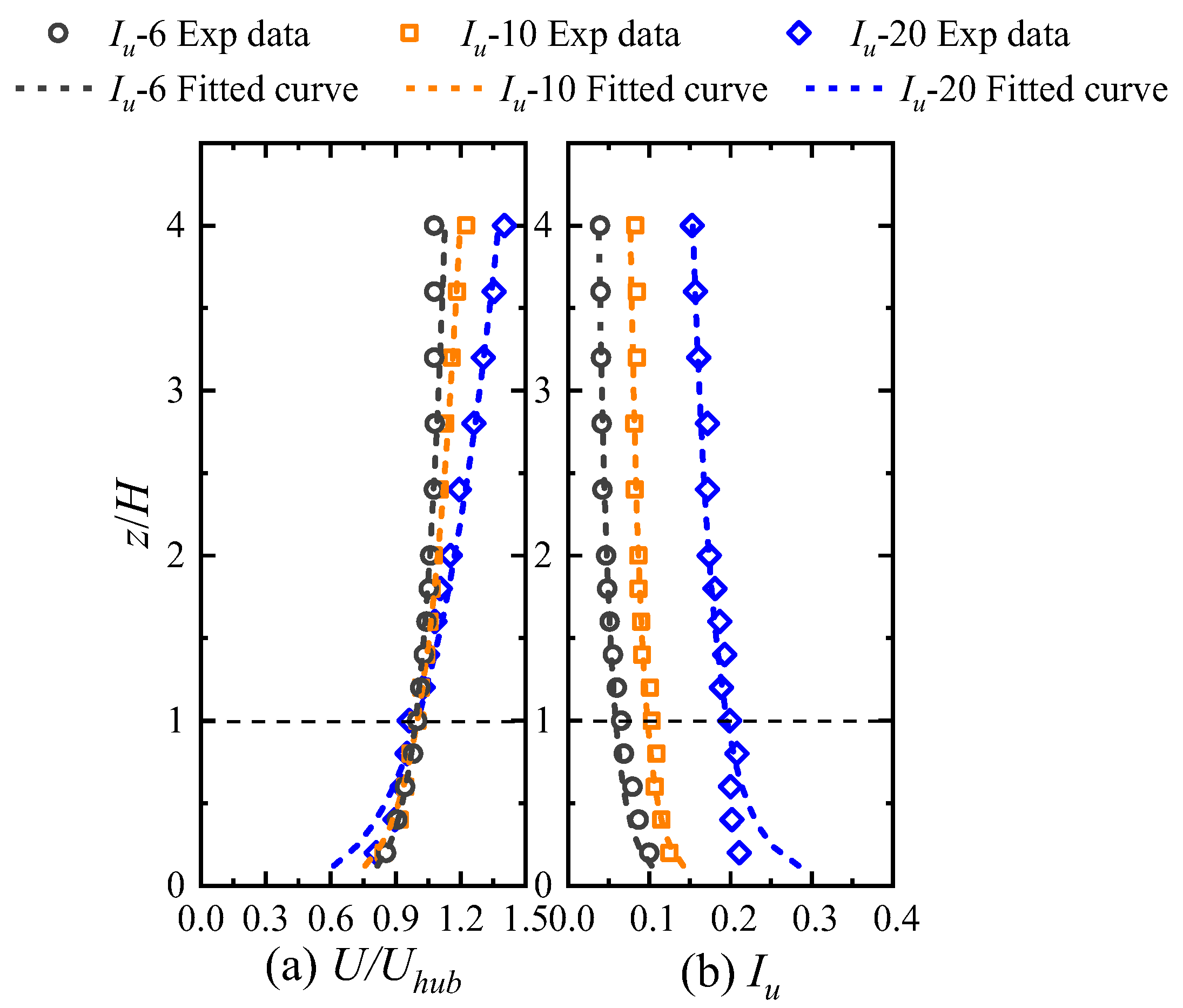
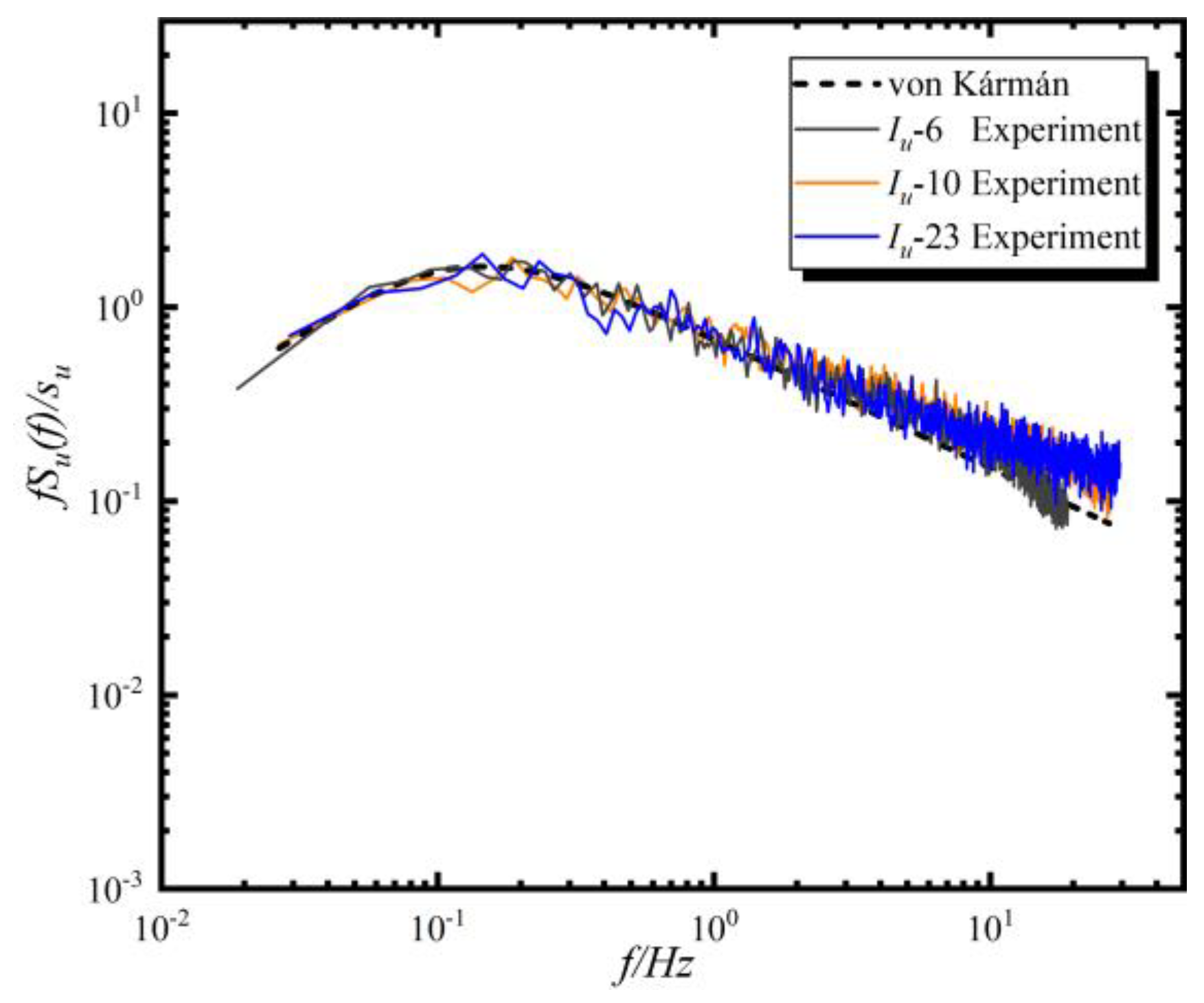
3.1. Inflow Condition

The vertical wind speed distribution is commonly modeled using the power law formulation [33], establishing the relationship between wind velocity U at elevation z and the reference velocity Uhub measured at hub height H:
U U h u b = z H α
where the constant exponent α characterizes terrain roughness. The ASCE standard classifies different α values corresponding to different terrain types [34]. Pre-installation flow characterization was conducted at two predetermined turbine locations (designated Position 1 and Position 2 in Figure 7) to establish baseline inflow conditions. Position 1 (x = −5D) serves as the reference case for inflow characterization (in Figure 8). Figure 8 presents the normalized mean velocity profile (U/Uhub) with Uhub = 6.5 m/s, along with the turbulence intensity defined per reference [35]:
I u = σ u / U h u b
where σu is the standard deviation of the streamwise velocity component at the hub height and the turbulence intensity can be effectively simulated. The incoming wind profile characterization was conducted during the wind tunnel commissioning phase without terrain features installed. The wind speed and turbulence intensity at the hub height, and the fitted power law exponent are summarized in Table 1. As demonstrated by Uchida [25] and Li et al. [36], turbulence intensity affects wake characteristics much more significantly than wind shear. Consequently, in this study, the inflow conditions are categorized into three levels: low turbulence (Iu-6), medium turbulence (Iu-10), and high turbulence (Iu-20). This classification aims to comprehensively investigate the impact of turbulent inflow on the wake of mountain wind turbines.
The power spectrum measured in the inflow at turbine hub height is shown in Figure 9. It was compared with one commonly used spectrum models for the stream-wise velocity component given by von Karman and Kaimal, and the measured spectrum agrees very well with the von Karman spectrum model [37]. Compared to low-turbulent-inflow conditions, the power spectra under high-turbulent-inflow conditions show a marked increase in kinetic energy in the high-frequency range. This suggests that high turbulent inflow has a substantial effect on the energy distribution within the flow field.

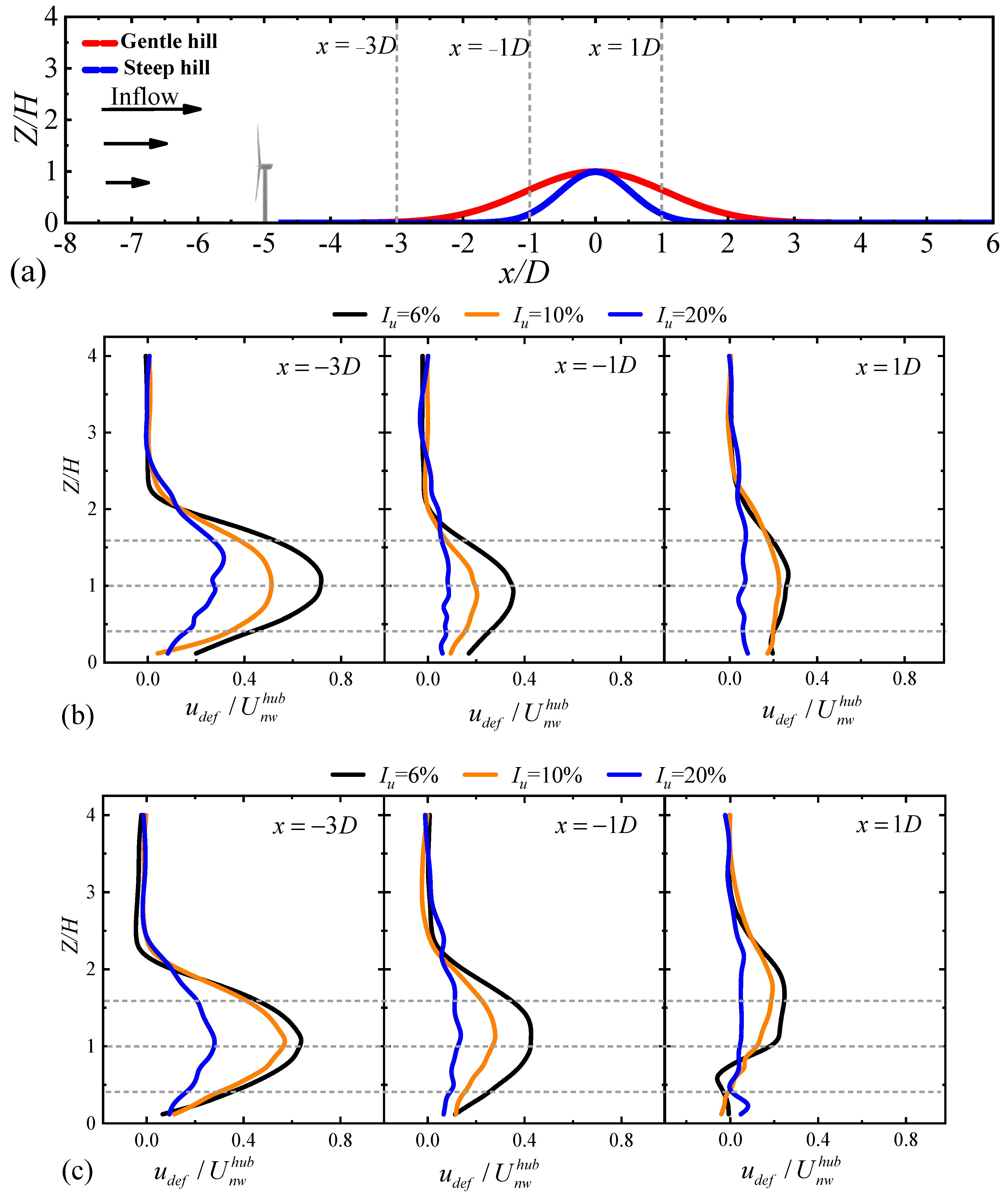
3.2. Wake Characteristics of Turbines in Front of the Hill

3.2.1. Velocity Deficit

In order to quantitatively analyze the effect of turbulent inflow on the wake characteristics of the wind turbine installed in front of the hill model, the streamwise velocity deficit was calculated.
For standardized comparison of terrain-induced wake velocity deficits, the Chen et al. [24] normalization approach was applied as follows:
u d e f U n w h u b = U n w h u b u w U n w h u b
where u d e f represents the velocity deficit, u w denotes the mean wind velocity over hill with turbine presence, and U n w h u b corresponds to the undisturbed flow at hub height without turbine interference. U n w h u b and u w in Equation (6) indeed represent wind speed vectors in the identical direction (streamwise flow).
Table 2 presents the key flow parameters at hub height without the presence of the wind turbine. Compared with the incoming wind speed shown in Section 3.1, it can be seen that the flow field at the upstream 5D position is slightly impacted by the hill, which is consistent with the phenomenon observed by Tian et al. [23].
To quantitatively asses the wake characteristic of the wind turbine situated in front of different hills, the vertical profiles of velocity deficit u d e f / U n w h u b at pre-installed locations (see Figure 10a) are displayed in Figure 10b,c. Both in gentle hill and steep hill cases, the velocity deficit is observed to be smaller in the higher turbulence inflow. For example, at x = −1D, the normalized velocity deficit decreases from 0.38 (low turbulence) to 0.04 (high turbulence) at the hub height for the gentle hill case and from 0.41 (low turbulence) to 0.09 (high turbulence) at the hub height for the steep hill case. This result indicates that a higher turbulence inflow leads to a faster recovery of wake velocity. The result is similar to that found by Wu and Porté-Agel with flat terrain [27], showing that ambient turbulence is the key factor to facilitate the wake recovery. Moreover, it can be seen that as the turbulence intensity of incoming flow increases, the wake flow becomes wider in the vertical direction. However, an interesting phenomenon is that in the case of the leeward side of the steep hill (x = 1D), it can be observed that the velocity deficits below hub height show minimal differences among the three turbulent inflow conditions due to strong flow separation induced by the steep hill. This contrasts with the gentle hill case (Figure 10b) at x = 1D, where velocity deficits vary significant vertically, demonstrating terrain-dependent wake modulation. At x = 1D under identical turbulent inflow conditions, the wake center exhibits a pronounced upward shift in the steep hill cases compared to the different streamwise locations, directly attributable to terrain-induced flow modification. Noting that the critical slope for the occurrence of flow separation over hilly terrain is approximately 0.3 [38], the uplifted wakes may be due to the flow separation over the steep hill with a slope of 0.5 in this study. A similar phenomenon was also observed by Tian et al. (2021) [16].

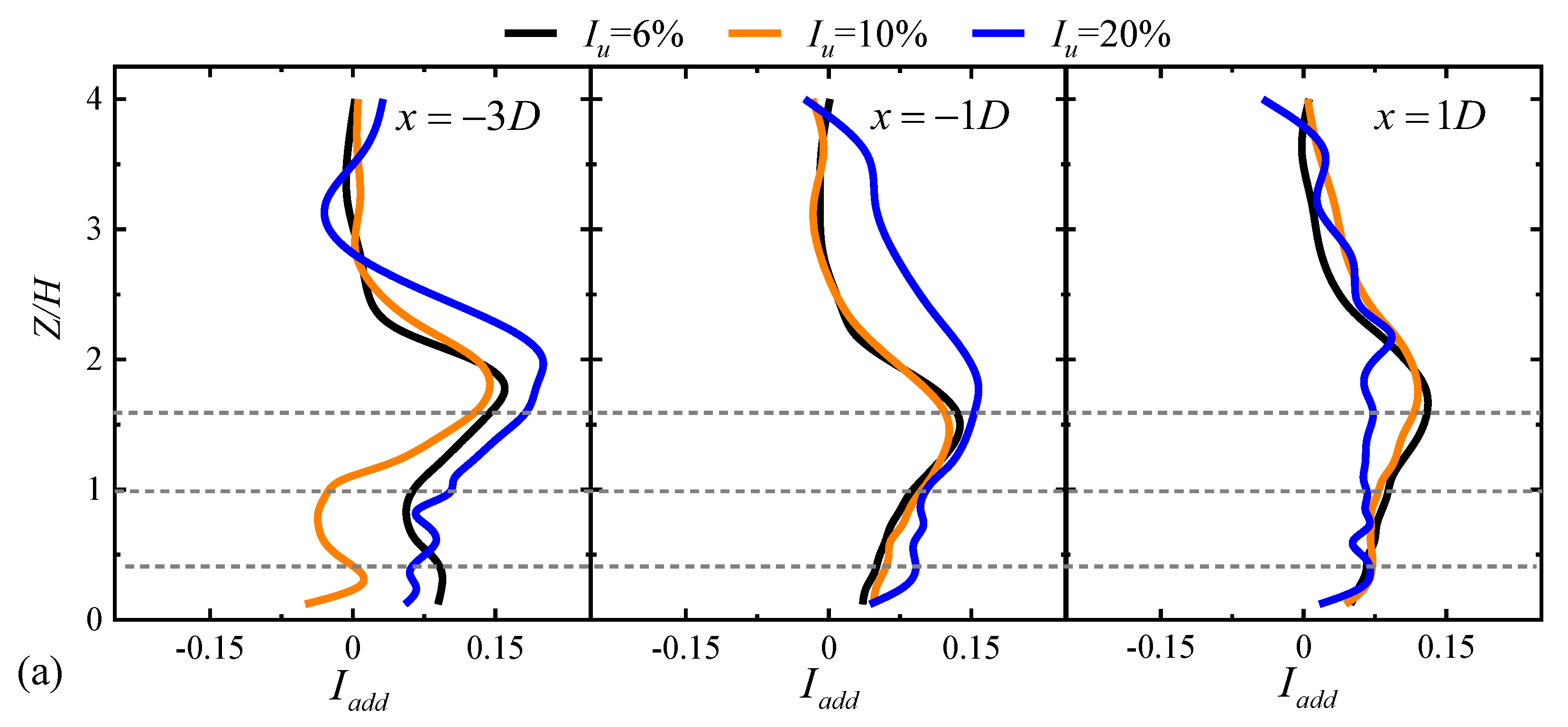
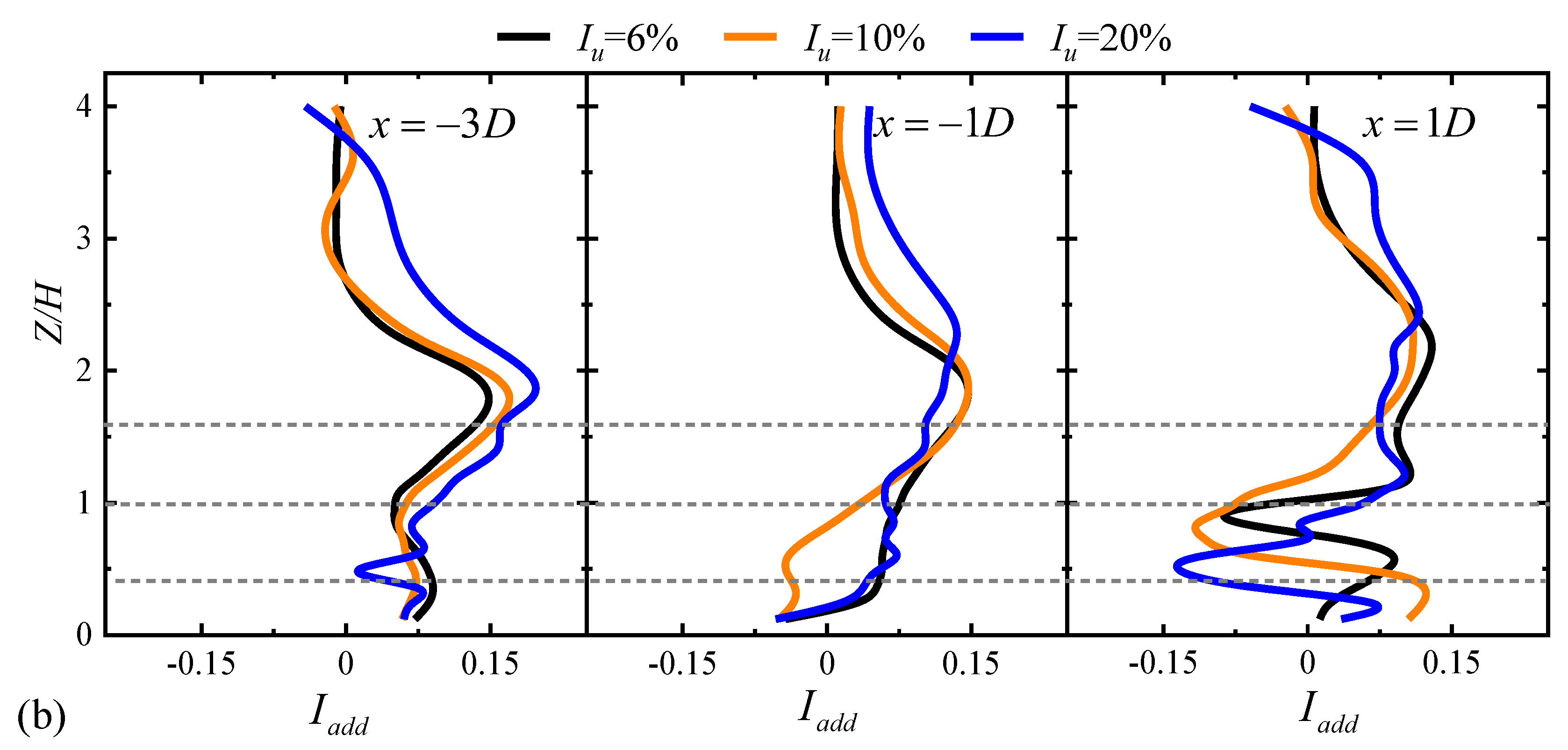
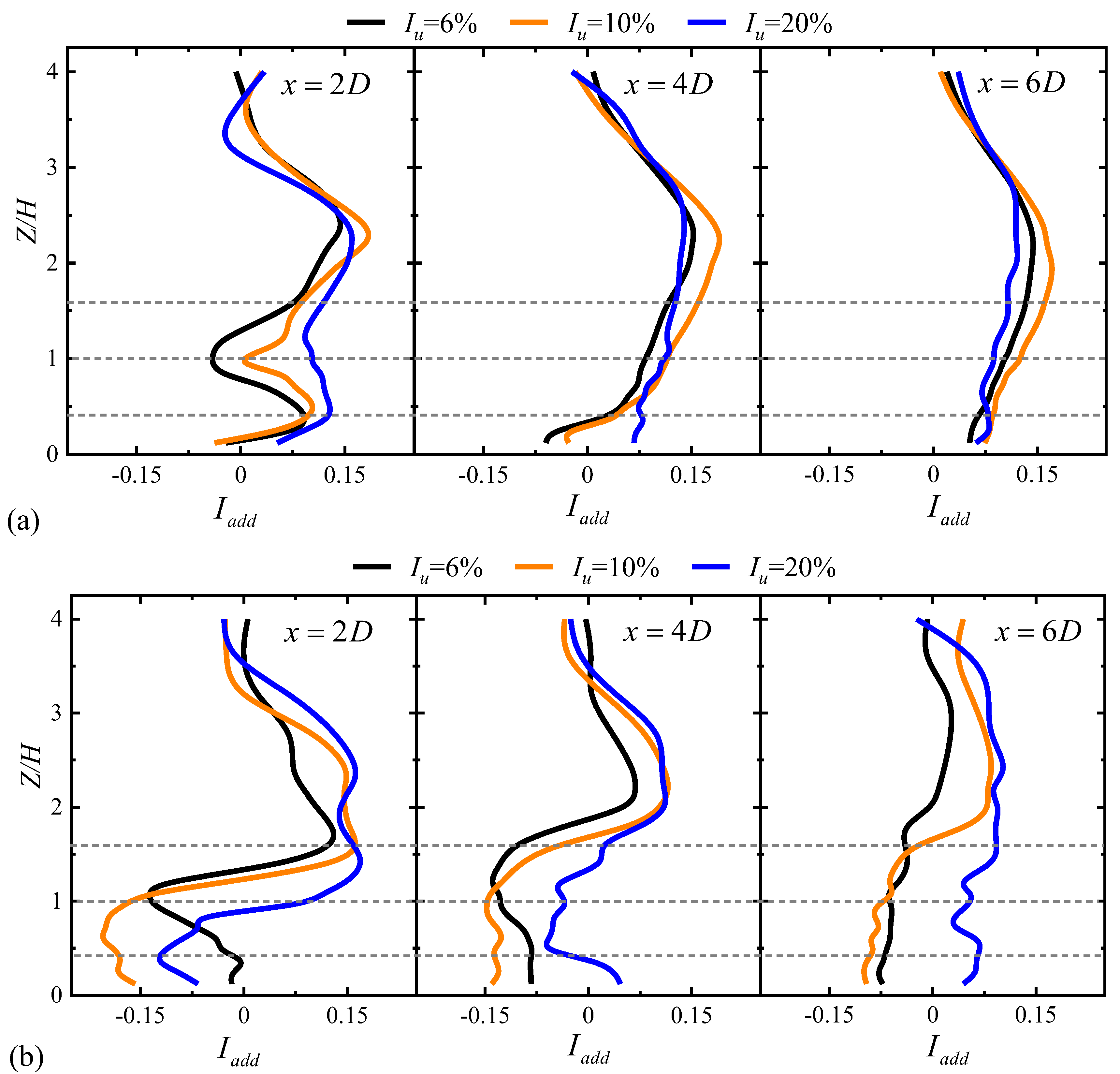
3.2.2. Added Turbulence Intensity

Consistent with the velocity deficit normalization, the turbulence intensity metrics ( I n w and I w ) are similarly nondimensionalized using U n w h u b , as mathematically formulated in Equations (6) and (7).
I n w = σ n w u / U n w h u b
I w = σ w u / U n w h u b
where σ n w u and σ w u denote the root mean square of streamwise velocity fluctuations for undisturbed and wake conditions, respectively. The turbine-induced turbulence enhancement is quantified through the added turbulence intensity:
I a d d = + I 2 w I 2 n w , I w I n w I 2 n w I 2 w , I w < I n w
where I w and I n w denote the turbulence intensity at the same location with and without the wind turbine, respectively.
Figure 11 presents vertical distributions of the turbulence intensity evolution ( I a d d ) at strategic downstream positions (Figure 10a), quantitatively characterizing wake development under different inflow turbulence conditions for hill-mounted turbines. Under three different turbulent inflow conditions, a significant increase in the added turbulence intensity is observed near the wake’s upper mixing layer, resulting from the strong shear on the windward side of both gentle and steep hills. Both in gentle hill and steep hill cases, the vertical distribution of I a d d exhibits asymmetry and an increasing trend. At x = −3D and x = −1D, it generally increases with higher inflow turbulence intensity, with its peak occurring near the upper tip region. This phenomenon results from the loss of coherence in vortex structures during the shedding of tip and hub vortices, combined with strong momentum exchange, which generates significant turbulent kinetic energy (TKE) between the outer and inner flow fields. However, this trend does not occur at x = 1D. Notably, in the steep hill, I a d d displays a multi-peak profile due to the combined effects of terrain blockage and recirculation, leading to positive values in the upper tip region and negative values near the hub height and lower tip region. It should be noted that the I a d d   in the case of I u = 20% is smaller than that of I u = 6% and I u = 10% over the leeward side in the gentle hill. This phenomenon revealed that the wake of the wind turbine over the leeward side of the gentle hill does not completely follow the trend where increased turbulence intensity leads to higher added turbulence. In addition, the distribution of I a d d shows a multi-peak shape profile at the location of the leeward side (x = 1D) in the steep hill case, which is also observed by Chen et al. [24]. This results from the suppression of enhanced velocity fluctuations arising from flow separation, which is influenced by the turbine-induced changes in flow shear. Furthermore, with the increased level of turbulent inflow, the peak value of I a d d at the lower edge of the turbine wakes becomes both larger in magnitude and lower in elevation.

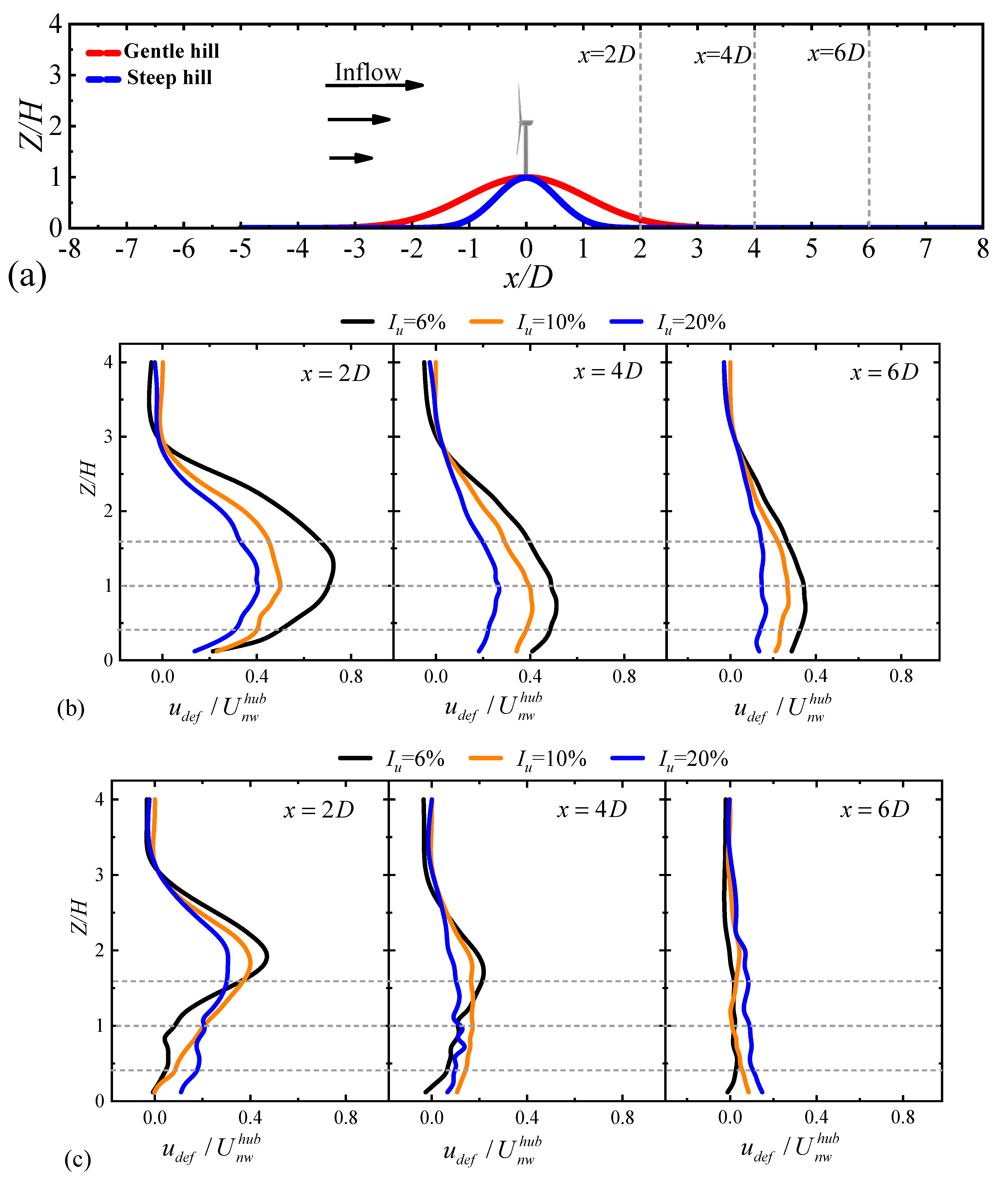
3.3. Wake Characteristics of Turbine on the Hilltop

3.3.1. Velocity Deficit

Consistent with the turbine in the front of hill case, Table 3 presents hub height flow characteristics for the hilltop configuration (without turbine). Compared to Table 2, the wind velocities on the hilltop are higher, and the level of the turbulence intensity are lower than in front of the hill due to the acceleration effect caused by the hill.
To compare the wake characteristic for the wind turbine located on the hilltop, the vertical profiles of velocity deficit are shown in Figure 11. Similarly to the case where the wind turbine is positioned in front of the hill, the wake of the wind turbine at the same location exhibits a similar evolution pattern under the three turbulent inflow conditions. Similarly to the turbine installed in front of the hill, the higher level of turbulence inflow leads to a lower velocity deficit and faster wake recovery. Additionally, by the comparison between Figure 10b and Figure 12b, the wake of the turbine located on the hilltop exhibits slower wake recovery in comparison with the turbine installed in front of the hill, which may result from the adverse pressure gradient on the leeward side of the hill [33]. While for the steep hill, the wake is relatively narrower than that in front of the hill, probably caused by the impact of flow separation. In steep hill cases, the wake recovery of wind turbine in the far wake region is faster than for the gentle hill.

3.3.2. Added Turbulence Intensity

As shown in Figure 13, the turbine installed on hilltop exhibits a distinct I a d d profile evolution: initial multi-peak distributions transition to single-peak patterns by x/D = 4, with this characteristic maintained across all tested terrain gradients. In the gentle hill case, the higher levels of turbulent inflow increase the I a d d within the range of rotor area in the near-wake region. Moreover, in the case of steep hilltop, the I a d d is greater under the condition of higher turbulent inflow levels. The results of I a d d indicate that the turbulence characteristic in the steep hill case exhibits an increased I a d d , while the gentle hill scenario does not show a similar increase in I a d d . According to previous studies of wake over flat terrain [26,27,28], it has been observed that the I a d d tends to be larger due to the enhanced turbulence mixing resulting from a higher turbulent inflow. However, under the coupled effect of turbulent inflow and terrain, this pattern does not hold, making the study of wake characteristic more complex.

4. Conclusions

This study systematically investigated the wake characteristics of wind turbines positioned over a two-dimensional hill under different turbulent inflow conditions. By conducting wind tunnel experiments for a scaled wind turbine model, the research examined the effects of turbulent inflow on the wake characteristics of the wind turbine, considering various turbine positions over the gentle hill and steep hill. The main conclusions are as follows:
(1)
The wake evolution under three turbulent inflow cases is different for the wind turbine located at different positions over the hill. Nonetheless, for turbulent inflow influence, the wakes generally follow a pattern where higher turbulent inflow leads to a faster recovery. Affected by the terrain, the wake center of the wind turbine in the steep hill will shift upward compared with the gentle slope case.
(2)
The I a d d profiles for the wind turbine located in front of the hill shows a multi-peak shape profile at the location of leeward side (x = 1D) in the steep hill, and the peak value at the lower edge of the turbine wakes becomes both larger in magnitude and lower in elevation.
(3)
The I a d d profiles for a turbine positioned on the hilltop show that the turbine-induced added turbulence intensity in steep hill cases was enhanced, while there was no such phenomenon observed in the gentle hill scenario.
This study aims to explore the influence of turbulent incoming flow and terrain slope on the wake dynamics of wind turbines. However, it still needs to be improved in the in-depth analysis part of the mechanism exploration, lacks consideration of the influence of terrain height and surface roughness on the turbine wake, and does not fully explore the influence of terrain on the thrust coefficient. These aspects will be addressed in future research work in combination with CFD.

Author Contributions

B.Y.: Conceptualization, Funding acquisition. S.T.: Writing—original draft, Formal analysis, Visualization. G.Q.: Writing—review & editing, Funding acquisition, Supervision. M.Y.: Data curation, Investigation. Y.C.: Software, Methodology. All authors have read and agreed to the published version of the manuscript.

Funding

The authors would like to acknowledge the financial support from the National Natural Science Foundation of China (Nos. 52221002 and 52278483), 111 Project of China (No. B18062), the National Key Research and Development Program of China (Grant No. 2022YFC2806300), Natural Science Foundation of Guangdong, China (No. 2024A1515010547), Natural Science Foundation of Chongqing, China (No. cstc2022ycjh-bgzxm0050), the Innovation Group Project of Southern Marine Science and Engineering Guangdong Laboratory (Zhuhai) (No. 311023014), and Fundamental Research Funds for the Central Universities (No. 2024CDJZCQ-011, and 23qnpy83).

Data Availability Statement

The original contributions presented in the study are included in the article. Further inquiries can be directed to the corresponding author.

Conflicts of Interest

The authors declare no conflicts of interest.

References

  1. Wang, D.; Feng, D.C.; Peng, H.W.; Mao, F.; Doranehgard, M.H.; Gupta, V.; Li, L.K.B.; Wan, M.P. Implications of steep hilly terrain for modeling wind-turbine wakes. J. Clean. Prod. 2023, 398, 136614. [Google Scholar] [CrossRef]
  2. Elgendi, M.; AlMallahi, M.; Abdelkhalig, A.; Selim, M.Y.E. A review of wind turbines in complex terrain. Int. J. Thermofluids 2023, 17, 100289. [Google Scholar] [CrossRef]
  3. Sanderse, B. Aerodynamics of Wind Turbine Wakes; Energy research Centre of the Netherlands (ECN): Petten, The Netherlands, 2009. [Google Scholar]
  4. Porté-Agel, F.; Bastankhah, M.; Shamsoddin, S. Wind-Turbine and Wind-Farm Flows: A Review. Bound-Lay. Meteorol. 2020, 174, 1–59. [Google Scholar] [CrossRef]
  5. Lubitz, W.D.; White, B.R. Wind-tunnel and field investigation of the effect of local wind direction on speed-up over hills. J. Wind Eng. Ind. Aerodyn. 2007, 95, 639–661. [Google Scholar] [CrossRef]
  6. Radünz, W.C.; Sakagami, Y.; Haas, R.; Petry, A.P.; Passos, J.C.; Miqueletti, M.; Dias, E. Influence of atmospheric stability on wind farm performance in complex terrain. Appl. Energy 2021, 282, 116149. [Google Scholar] [CrossRef]
  7. Menke, R.; Vasiljević, N.; Hansen, K.S.; Hahmann, A.N.; Mann, J. Does the wind turbine wake follow the topography? A multi-lidar study in complex terrain. Wind. Energ. Sci. 2018, 3, 681–691. [Google Scholar] [CrossRef]
  8. Gao, X.; Chen, Y.; Xu, S.; Gao, W.; Zhu, X.; Sun, H.; Yang, H.; Han, Z.; Wang, Y.; Lu, H. Comparative experimental investigation into wake characteristics of turbines in three wind farms areas with varying terrain complexity from LiDAR measurements. Appl. Energy 2022, 307, 118182. [Google Scholar] [CrossRef]
  9. Sun, H.; Yang, H.; Gao, X. Investigation into wind turbine wake effect on complex terrain. Energy 2023, 269, 126767. [Google Scholar] [CrossRef]
  10. Hansen, K.S.; Larsen, G.C.; Menke, R.; Vasiljevic, N.; Angelou, N.; Feng, J.; Zhu, W.J.; Vignaroli, A.; Liu, W.W.; Xu, C.; et al. Wind turbine wake measurement in complex terrain. J. Phys. Conf. Ser. 2016, 753, 032013. [Google Scholar] [CrossRef]
  11. Seim, F.; Gravdahl, A.R.; Adaramola, M.S. Validation of kinematic wind turbine wake models in complex terrain using actual windfarm production data. Energy 2017, 123, 742–753. [Google Scholar] [CrossRef]
  12. Yang, X.; Howard, K.B.; Guala, M.; Sotiropoulos, F. Effects of a three-dimensional hill on the wake characteristics of a model wind turbine. Phys. Fluids 2015, 27, 025103. [Google Scholar] [CrossRef]
  13. Dar, A.S.; Berg, J.; Troldborg, N.; Patton, E.G. On the self-similarity of wind turbine wakes in a complex terrain using large eddy simulation. Wind Energy Sci. 2019, 4, 633–644. [Google Scholar] [CrossRef]
  14. Shamsoddin, S.; Porté-Agel, F. Wind turbine wakes over hills. J. Fluid Mech. 2018, 855, 671–702. [Google Scholar] [CrossRef]
  15. Nedjari, H.D.; Guerri, O.; Saighi, M. CFD wind turbines wake assessment in complex topography. Energy Convers. Manag. 2017, 138, 224–236. [Google Scholar] [CrossRef]
  16. Tian, W.; Zheng, K.; Hu, H. Investigation of the wake propagation behind wind turbines over hilly terrain with different slope gradients. J. Wind Eng. Ind. Aerodyn. 2021, 215, 104683. [Google Scholar] [CrossRef]
  17. Politis, E.S.; Prospathopoulos, J.; Cabezon, D.; Hansen, K.S.; Chaviaropoulos, P.K.; Barthelmie, R.J. Modeling wake effects in large wind farms in complex terrain: The problem, the methods and the issues. Wind Energy 2012, 15, 161–182. [Google Scholar] [CrossRef]
  18. Howard, K.B.; Chamorro, L.P.; Guala, M. An Experimental Case Study of Complex Topographic and Atmospheric Influences on Wind Turbine Performance. In Proceedings of the 51st AIAA Aerospace Sciences Meeting including the New Horizons Forum and Aerospace Exposition, Grapevine (Dallas/Ft. Worth Region), TX, USA, 7–10 January 2013. [Google Scholar]
  19. Howard, K.B.; Hu, J.S.; Chamorro, L.P.; Guala, M. Characterizing the response of a wind turbine model under complex inflow conditions. Wind Energy 2015, 18, 729–743. [Google Scholar] [CrossRef]
  20. Hyvärinen, A.; Segalini, A. Effects from Complex Terrain on Wind-Turbine Performance. J. Energy Resour. Technol. 2017, 139, 051205. [Google Scholar] [CrossRef]
  21. Lange, J.; Mann, J.; Berg, J.; Parvu, D.; Kilpatrick, R.; Costache, A.; Chowdhury, J.; Siddiqui, K.; Hangan, H. For wind turbines in complex terrain, the devil is in the detail. Environ. Res. Lett. 2017, 12, 094020. [Google Scholar] [CrossRef]
  22. Nanos, E.M.; Yilmazlar, K.; Zanotti, A.; Croce, A.; Bottasso, C.L. Wind tunnel testing of a wind turbine in complex terrain. J. Phys. Conf. Ser. 2020, 1618, 032041. [Google Scholar] [CrossRef]
  23. Tian, W.; Ozbay, A.; Hu, H. An experimental investigation on the aeromechanics and wake interferences of wind turbines sited over complex terrain. J. Wind Eng. Ind. Aerodyn. 2018, 172, 379–394. [Google Scholar] [CrossRef]
  24. Chen, Y.; Yan, B.; Yu, M.; Huang, G.; Qian, G.; Yang, Q.; Zhang, K.; Mo, R. Wind tunnel study of wind turbine wake characteristics over two-dimensional hill considering the effects of terrain slope and turbine position. Appl. Energy 2025, 380, 125044. [Google Scholar] [CrossRef]
  25. Uchida, T. Effects of Inflow Shear on Wake Characteristics of Wind-Turbines over Flat Terrain. Energies 2020, 13, 3745. [Google Scholar] [CrossRef]
  26. Wu, Y.-T.; Lin, C.-Y.; Chang, T.-J. Effects of inflow turbulence intensity and turbine arrangements on the power generation efficiency of large wind farms. Wind Energy 2020, 23, 1640–1655. [Google Scholar] [CrossRef]
  27. Wu, Y.-T.; Porté-Agel, F. Atmospheric Turbulence Effects on Wind-Turbine Wakes: An LES Study. Energies 2012, 5, 5340–5362. [Google Scholar] [CrossRef]
  28. Vahidi, D.; Porté-Agel, F. Influence of incoming turbulent scales on the wind turbine wake: A large-eddy simulation study. Phys. Fluids 2024, 36, 095177. [Google Scholar] [CrossRef]
  29. Barthelmie, R.J.; Schepers, J.; Pihl, S.V.; Rathmann, O.; Frandsen, S.T.; Cabezón, D.; Politis, E.S.; Prospathopoulos, J.M.; Rados, K.; Hansen, K.S.; et al. Flow and wakes in complex terrain and offshore. Model development and verification in UPWIND. In Proceedings of European Wind Energy Conference & Exhibition 2007, Milan, Italy, 7–10 May 2007. [Google Scholar]
  30. Barthelmie, R.J.; Frandsen, S.T.; Rathmann, O.; Hansen, K.; Politis, E.S.; Prospathopoulos, J.; Cabezon, D.; Rados, K.; Pijl, S.P.; Schepers, J.G.; et al. Flow and wakes in large wind farms in complex terrain and offshore. In Proceedings of the 2008 European Wind Energy Conference and Exhibition, Brussels, Belgium, 31 March–3 April 2008; pp. 36–40. [Google Scholar]
  31. Huang, G.; Zhang, S.; Yan, B.; Yang, Q.; Zhou, X.; Ishihara, T. Thrust-matched optimization of blades for the reduced-scale wind tunnel tests of wind turbine wakes. J. Wind Eng. Ind. Aerodyn. 2022, 228, 105113. [Google Scholar] [CrossRef]
  32. Yang, W.; Yu, M.; Yan, B.; Huang, G.; Yang, Q.; Zhang, S.; Hong, T.; Zhou, X.; Deng, X. Wind Tunnel Tests of Wake Characteristics for a Scaled Wind Turbine Model Based on Dynamic Similarity. Energies 2022, 15, 6165. [Google Scholar] [CrossRef]
  33. Shamsoddin, S.; Porté-Agel, F. A model for the effect of pressure gradient on turbulent axisymmetric wakes. J. Fluid Mech. 2018, 837, R3. [Google Scholar] [CrossRef]
  34. Zhou, Y.; Kareem, A. Definition of Wind Profiles in ASCE 7. J. Struct. Eng. 2002, 128, 1082–1086. [Google Scholar] [CrossRef]
  35. Chamorro, L.P.; Porté-Agel, F. A Wind-Tunnel Investigation of Wind-Turbine Wakes: Boundary-Layer Turbulence Effects. Bound-Lay. Meteorol. 2009, 132, 129–149. [Google Scholar] [CrossRef]
  36. Li, Q.; Murata, J.; Endo, M.; Maeda, T.; Kamada, Y. Experimental and numerical investigation of the effect of turbulent inflow on a Horizontal Axis Wind Turbine (part II: Wake characteristics). Energy 2016, 113, 1304–1315. [Google Scholar] [CrossRef]
  37. Von Kármán, T. Progress in the statistical theory of turbulence. Proc. Natl. Acad. Sci. USA 1948, 34, 530–539. [Google Scholar] [CrossRef] [PubMed]
  38. Mason, P.J.; King, J.C. Measurements and predictions of flow and turbulence over an isolated hill of moderate slope. Q. J. R. Meteorol. Soc. 1985, 111, 617–640. [Google Scholar] [CrossRef]
Figure 1. Schematic diagram of the experimental wind tunnel setup. A-A denotes the test section cross-section.
Energies 18 02865 g001
Figure 2. Field layout of the three types of passive devices for different inflow conditions: (a) Iu = 6%, (b) Iu = 10%, (c) Iu =20%. Iu represents the turbulence intensity derived from hub elevation.
Energies 18 02865 g002
Figure 3. Wind turbine model.
Energies 18 02865 g003
Figure 4. CT-TSR correlation from experimental measurements. Operational point for wake studies is highlighted in red dot.
Energies 18 02865 g004
Figure 5. Terrain cross-sections with distinct slope gradients: (a) s = 0.25; (b) s = 0.5.
Energies 18 02865 g005
Figure 6. Schematic representation of the experimental apparatus and data acquisition system.
Energies 18 02865 g006
Figure 7. Schematic diagram of wind tunnel measurements carried out in this study.
Energies 18 02865 g007
Figure 8. Vertical distributions of (a) the normalized mean streamwise velocity and (b) streamwise direction turbulence intensity. The horizontal dashed reference line indicates the turbine’s rotor plane elevation. The turbulence intensity profile was fitted using the power-law function specified in ASCE 7 [34].
Energies 18 02865 g008
Figure 9. The power spectral density of the stream-wise velocity component measured at turbine hub height in comparison with the von Kármán [37] design curve.
Energies 18 02865 g009
Figure 10. Velocity deficit in the wake of a wind turbine positioned in front of the hilltop: (a) spatial configuration schematic, (b) vertical profile variations at selected downstream for the gentle hill case, and (c) vertical profile variations at selected downstream for the steep hill case. Horizontal dashed lines indicate the rotor axis and tip positions.
Energies 18 02865 g010
Figure 11. Vertical distributions of I a d d for a wind turbine positioned in front of the hilltop: (a) gentle hill and (b) steep hill. Horizontal dashed lines indicate the rotor axis and tip positions.
Energies 18 02865 g011aEnergies 18 02865 g011b
Figure 12. Velocity deficit in the wake of a wind turbine positioned on the hilltop: (a) spatial configuration schematic, (b) vertical profile variations at selected downstream for the gentle hill case, and (c) vertical profile variations at selected downstream for the steep hill case. Horizontal dashed lines indicate the rotor axis and tip positions.
Energies 18 02865 g012
Figure 13. Vertical distributions of I a d d for a wind turbine positioned on the hilltop: (a) gentle hill and (b) steep hill. Horizontal dashed lines indicate the rotor axis and tip positions.
Energies 18 02865 g013
Table 1. Information on ABL with different turbulent inflow.
CasesUhub (m/s)Iu (-)α (-)
Low turbulence6.56%0.07
Medium turbulence10%0.12
High turbulence20%0.23
Table 2. Summary of undisturbed inflow parameters at turbine locations in the absence of the wind turbine.
Gentle HillSteep Hill
U n w h u b (m/s) I u (%) U n w h u b (m/s) I u (%)
Iu = 6%6.3 6.7 6.5 6.5
Iu = 10%6.610.06.710.1
Iu = 20%6.1 21.0 6.2 21.7
Table 3. Summary of undisturbed inflow parameters at turbine locations in the absence of the wind turbine.
CasesGentle HillSteep Hill
U B W F h u b (m/s) I u (%) U B W F h u b (m/s) I u (%)
Iu = 6%8.2 3.9 8.04.1
Iu = 10%8.5 9.98.29.8
Iu = 20%9.3 12.3 8.8 13.6
Disclaimer/Publisher’s Note: The statements, opinions and data contained in all publications are solely those of the individual author(s) and contributor(s) and not of MDPI and/or the editor(s). MDPI and/or the editor(s) disclaim responsibility for any injury to people or property resulting from any ideas, methods, instructions or products referred to in the content.

