1. Introduction
Multiphase Drives (m-D) have experienced significant interest in a wide range of industry applications where the safety and high reliability of operation are key items. With an increased number of phases (more than three) and more degrees of freedom [
1], multiphase machines provide more opportunities in terms of their fault diagnosis and fault tolerability, especially for applications such as electric vehicles, aerospace applications [
2], energy generation [
3], and automotive traction applications [
4], where the safety and high reliability of the operation are key items.
Multiphase Permanent-Magnet Synchronous Motors (m-ph PMSMs) take advantage of the powerful strengths of multiphase machines, when compared to the classical three-phase machines, such as lowering the torque ripple, lower current harmonics, and a higher torque/power switch rating. The interest for m-ph PMSMs can be explained by the inherent active stator phase redundancy structure offering a greater degree of freedom which improves substantially the fault tolerance capabilities of the drive [
1,
5]. Among different topologies of multiphase drives, the multiple three-phase ones (dual, triple, or quadruple), based on the standard three-phase technology, are particularly attractive [
6,
7].
Having more than three phases, m-ph PMSMs are more exposed to several stator faults than 3-ph PMSMs. Generally, stator faults are initiated by the combination of different phenomena, namely electromechanical stresses, thermal cycling, damages in the contact surfaces, and/or insulations due to chemical stress accelerated by humidity and corrosion. If not detected, the propagation of the above phenomena can lead to excessive local overheating with the risk of dangerous arcing. Comprehensive descriptions and an analysis of stator faults mechanism propagation, introduced by a mixed effect of the above factors, are established in [
8], and more recently in [
9,
10].
Therefore, it is important to perform an effective fault diagnosis process so the faults can be detected, and the risk of sudden catastrophic failure is eliminated. Furthermore, it provides an accurate basis for selecting the adequate subsequent fault-tolerant control strategy to be adopted, so a continuity of service can be ensured.
Different forms of stator failures can affect m-ph PMSMs such as Open-Phase (OPh), Inter-Turn Short-Circuit (ITSC), Phase-to-Phase (PP), Coil-to-Coil (CC), or Coil-to-Ground (CG). Obviously, the consequences on the safety and performance of the machine are different. Specifically, OPh faults are the most frequent stator faults affecting electrical machines.
The literature on fault diagnosis and fault-tolerant strategies for electrical machines has increased rapidly during the last two decades [
11,
12,
13,
14], where techniques for stator fault detection have considerably evolved, and even reached a significant maturity level for multiphase motors [
15,
16,
17,
18].
Commonly, fault diagnosis strategies can be roughly classified as model-based techniques (MB), knowledge-based techniques (KB), signal-based techniques (SB), and hybrid fault diagnosis approaches. Specifically, OPh fault diagnostic techniques can be classified into two main categories, MB techniques and SB techniques. MB techniques evaluate the difference between the instantaneous drive’s response and the expected response issued from a healthy model, which is adopted for fault detection [
19,
20,
21]. However, these methods face key challenges, which are mainly related to the estimation errors that arise from the inherent inaccuracies of the idealized or assumed model against real-time operation, including the sensitivity to parameter changes, presence of noise and local disturbances, and the inevitable computational latency [
17,
22]. The above issues can be addressed using adaptive, robust, or intelligent control strategies; however, these algorithms commonly increase the complexity of treatments, leading inevitably to latency increments of the calculation [
17,
19,
20,
21,
22].
On the other hand, SB techniques are well suited to cope with the above main limitations of MB techniques, which justify the significant advances of SB techniques for diagnosing OPh faults in multiphase machines during the last decade [
16,
17].
In [
23], OPh fault detection and localization is based on the current symmetrical components investigation. The proposed method is based on the pattern analysis of the magnitude and phase angle changes of the fundamental signal. This approach has shown its effectiveness under complicated conditions including a single OPh fault, two-phase adjacent fault, and two-phase nonadjacent fault. The approach proposed in [
24] is based on the analysis of the magnetic field pendulous oscillation phenomenon, in which a significant “swing-like” pendulous oscillation in the magnetic field is observed in the case of OPh faults. To minimize the number of sensors, a phase-locked loop technique was developed to overcome the masking effect associated with the compensation action of the closed-loop vector-controlled drive. Thus, four current sensors and a speed sensor are required, which are typically available in five-phase PMSM drives. The performance of this technique has been proved for different OPh configurations, namely single OPh faults, two-adjacent OPh faults, and two non-adjacent OPh faults.
In [
25], the approach for OPh fault detection is based on the simultaneous evaluation of the average value of the absolute value of the current and the instantaneous speed. In [
26], the fault diagnosis algorithm is based on the interpretation of the reference current errors and the second-order harmonic of the secondary currents in a synchronous reference frame.
Diagnosis techniques for detecting and localizing OPh faults can be further partitioned into Phase Current Monitoring (PhCM) and Current-based Multiple-space Vector Transformation (C-MsVT). Different interesting techniques based on PhCM have been developed for the diagnosis of OPh faults [
25,
27,
28]. Although these techniques are reliable, the large detection time remains the main problem of these approaches. Specifically, the checking process of whether the absolute or squared values of the phase currents are nearing zero during the required fundamental cycles, leading commonly to an easily triggered false alarm, remains the main problem of these approaches.
More recently, by taking advantage of the additional degrees of freedom in multiphase machines, different techniques using C-MsVT have been proposed for the diagnosis of OPh faults by exploiting the fault signatures in the different α-β subspaces. The use of the fundamental α
1-β
1 and the secondary x–y subspaces, issued from C-MsVT, has shown very interesting results for diagnosing this type of faults in [
29,
30,
31,
32]. For a more effective and accurate diagnosis of OPh faults, an innovative technique based on the combined use of PhCM and C-MsVT has been proposed in [
33]. Finally, it is worth noting that the interest for the secondary x–y subspaces is mainly justified by the fact that their values are decoupled from fundamental α
1-β
1, and they typically exhibit significant changes under OPh faults.
Despite the advantages of the C-MsVT, the complexity of combining the fault signatures issued from the different subspaces remains the main limitation of these techniques. In addition, most of the C-MsVT’s proposed strategies are based on zero-current harmonics, and the sensitivity against the presence of harmonic disturbances is not analyzed, except for in [
22,
32].
In this context, an effective OPh fault diagnosis strategy that is independent of possible harmonic disturbances, and which exploits a single secondary x–y subspace, is highly recommended. In addition, an effective diagnostic process should not require extra hardware equipment and/or specialized sensors for acquiring the minimum of the measurements from the machine drive to be analyzed, so an accurate fault signature can be extracted in a minimum time. Despite the benefits of each diagnosis strategy, signal-based approaches are easy to implement and are generally the preferred approach [
11,
12,
17].
Motivated by the potential of the C-MsVT, the lack of use of Voltage-based Multiple-space Vector Transformation (V-MsVT) and the need to overcome some of the above limitations related to MB and SB techniques, an effective strategy for the diagnosis of open-phase faults in closed-loop controlled six-phase AC permanent-magnet motors, which is based on the analysis of a single x–y subspace, is proposed in this paper.
Being the starting point of any category of a signal-based approach, the current signature analysis and voltage signature analysis for detecting an OPh fault in closed-loop vector-controlled asymmetrical six-phase PMSM are assessed. Specifically, it is shown that the presence of the relevant disturbing harmonics observed, when using V-MsVT, affects considerably the derived fault signature. To cope with this limitation a diagnostic space vector, issued from V-MsVT evaluated in the α5-β5 subspace, is proposed here. The proposed approach has shown its effectiveness not only using V-MsVT, but also using C-MsVT, leading to sensible improvements of both fault signatures for detecting and localizing OPh faults.
This paper is organized as follows. Modeling in terms of the multiple-space vector transformation of the investigated 6-φ PMSM is presented in
Section 2. Numerical simulations and experimental tests are presented and commented on
Section 3 and
Section 4, respectively.
2. Control and Modeling of Six-Phase PMSM
The principle of multiple-space vector transformation for a set of six variables and then the analytical modeling of the six-phase drive system are presented in this section.
The mathematical model of an asymmetrical six-phase machine could be expressed in terms of phase variables (, , , , , ). However, due to the mutual magnetic coupling among the six stator windings, the equations would turn out to be closely interconnected and, therefore, difficult to interpret and solve.
The Multiple-space Vector Transformation (MsVT) concept is a very useful approach for the modeling, analysis, and control design of multiphase machines and drives [
34]. It allows the decomposition of the
space in three orthogonal and independent planes, leading to a more compact and simpler machine model, which is constituted by independent equations.
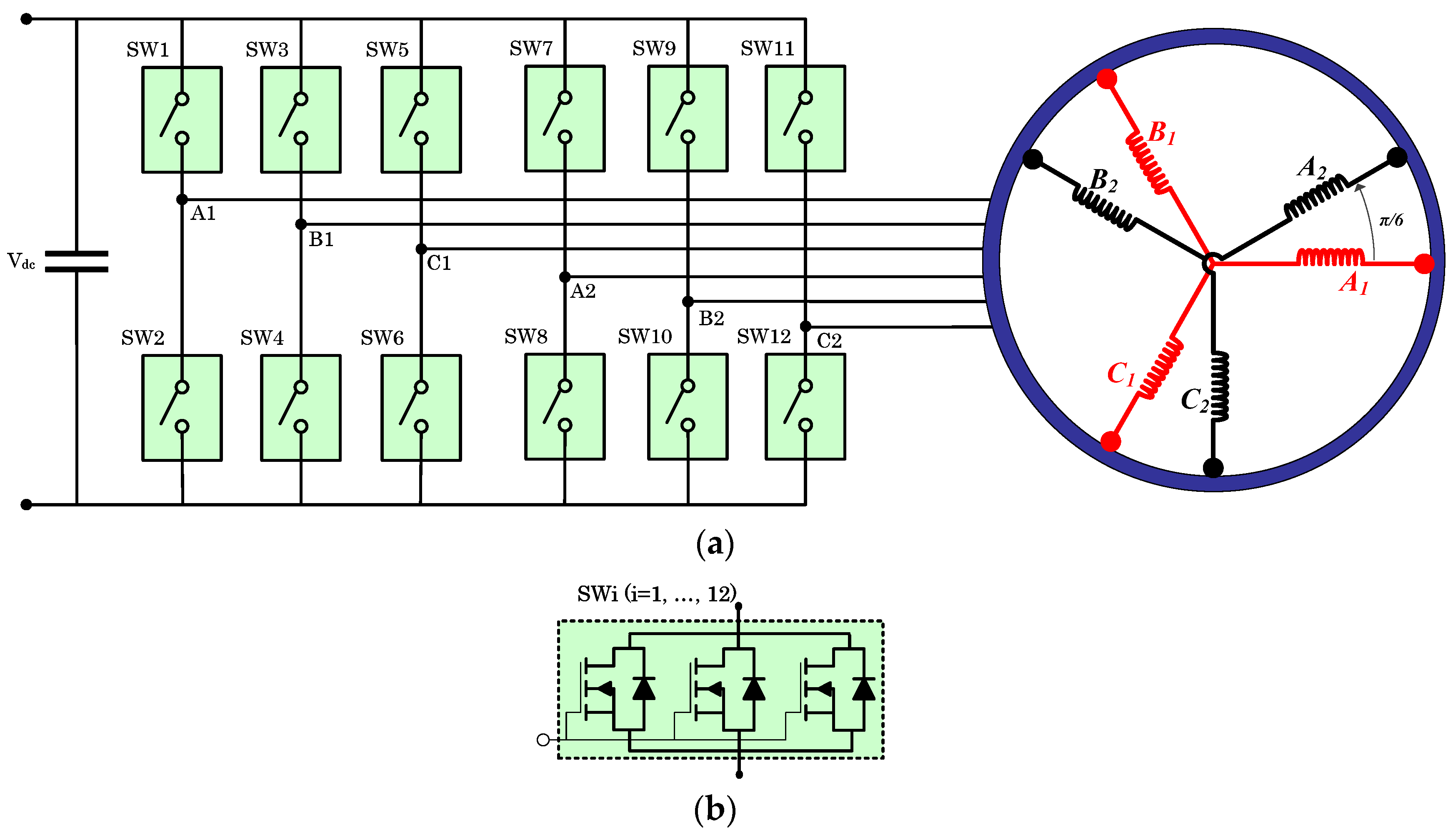
Note that the transformation to be used depends on the relative position of the magnetic axes of the six stator windings. For an asymmetrical six-phase machine, having the six stator windings distributed as shown in
Figure 1a, the proper direct and inverse transformations, which correlate the set of six real variables,
,
,
,
,
, and
, to a new set of three complex variables (space vectors),
,
, and
, can be formulated by (1) and (2), respectively.
where
, the symbol “.” identifies the scalar product, and “*” is the complex conjugate.
It should be emphasized that the behavior of the six-phase electrical quantities of the machine (voltages, currents, and fluxes) can be described by the trajectories of the three space vectors , , and , which independently move within their orthogonal subspaces, α1-β1, α3-β3, and α5-β5, respectively.
The considered machine is a 30° asymmetrical six-phase AC surface-mounted PMSM, as illustrated in
Figure 1a.
The dynamic model of the asymmetrical six-phase surface-mounted PMSM relies on the typical simplifying assumptions adopted for analyzing AC rotating electrical machines. In particular, the iron losses in stator and rotor cores are neglected, the magnetic materials’ permeability is assumed to be very high, the saturation effects are supposed to be negligible, and all cross sections of the machine are considered equivalent. The model, which is valid in a steady state as well as transient operating conditions, takes the effects of the magnetic field in the air gap up to the eleventh spatial harmonic into account. Based on the concept of MsVT, the electrical quantities are developed in a stationary reference frame.
The six stator voltage equations can be formulated for the two sets (
k = 1, 2) of three phase systems as
Based on the direct transformation (1), the stator voltage expressions (3) can be reformulated, leading to a new set of three stator voltage space vectors given by:
where
,
, and
are the space vectors in the
planes of the stator voltages, stator currents, and linkage fluxes, respectively, whereas
is the stator resistance.
The stator flux space vectors can be expressed by
In (7)–(9),
θ is the rotor position in electrical radians, whereas the constant values
can be expressed as in (10), respectively. Furthermore,
,
, and
are given by (11)–(13), respectively.
Taking the previous equations into account, and considering a power balance, the electromagnetic torque can be formulated as the sum of six contributions by
where
It can be noted that, besides the fundamental component , the torque contains several additional oscillating contributions that can be compensated by using a suitable machine design and current control techniques.
An improved FOC scheme is adopted to control the six-phase PMSM (
Figure 2).
For a better analysis of the FOC strategy, it is useful to reformulate the voltage equations in the rotating reference frames. As the stator windings design has two separated neutral points (
Figure 1a), the current space vector in the third subspace is equal to zero. Hence, the set of three voltage Equations (4)–(6) expressed in the stator reference frame, can be limited to the 1st and 5th subspaces.
Assuming the adopted stator windings design, the voltage equations written in the rotating reference frames lead to:
Basically, four current regulators (PI+1,d, PI+1,q) and (PI+5,d, PI+5,q) have been implemented in the 1st and 5th d-q rotor reference frames, respectively.
In order to enhance the current tracking performance in planes d1-q1 and d5-q5, and to reduce the torque ripple, an improved (IFOC) is adopted, which includes four additional regulators, (PI−11,d, PI−11,q) and (PI−7,d, PI−7,q), implemented in reference frames synchronous with the eleventh and seventh harmonics of the back-emfs, respectively.
In this way, the fifth and seventh harmonics of the stator current are zero and, consequently, the fifth and seventh harmonics of the reference voltage in the fifth space v̅S5,ref
coincide with the fifth and seventh harmonic of the EMFs, respectively.
In the next sections, the spectral aspects of the current and voltage space vectors in the fifth plane, with and without the presence of an OPF, will be analyzed by simulations and experimental tests.
3. Simulation Results
In order to assess the detectability and localization aspects of OPh faults, based on CSA and VSA, a complete simulation scheme of a six-phase PMSM controlled by the IFOC scheme shown in
Figure 2 has been implemented in Matlab/Simulink
TM. The main machine parameters are reported in
Table 1. A duration of 10 s with a sampling rate of 5.0 kHz for data acquisition and frequency domain analysis have been adopted.
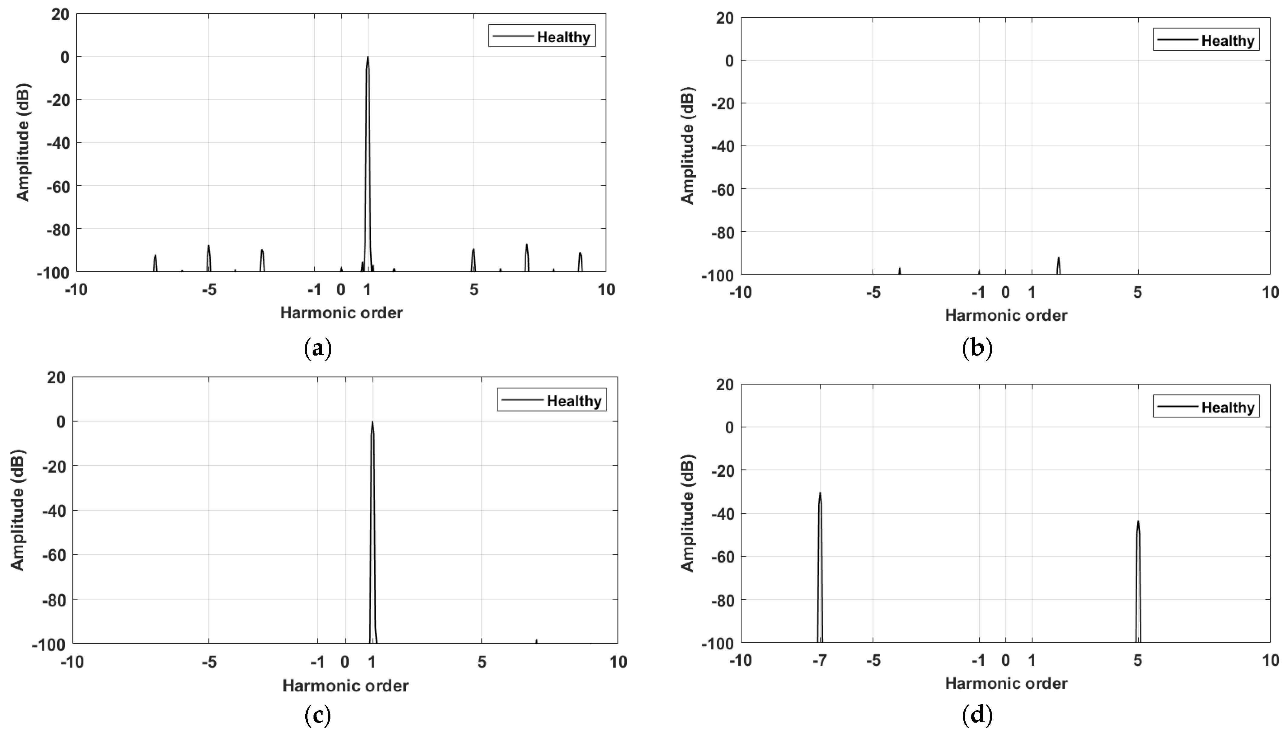
Simulations were first carried out under a healthy condition with 150 rpm and 25% of the rated load. The behavior of the healthy machine under the healthy condition is shown in
Figure 3,
Figure 4 and
Figure 5. The time-domain waveforms of the six-phase currents are reported in
Figure 3, where the currents are balanced due to the identical-stator six-phase impedances. The spectra of the current space vectors, evaluated in the first and fifth subspaces, are reported in
Figure 4a,b, respectively, where only the fundamental component is present in
, whereas a zero dB is observed in
.
In terms of the voltage space vectors, the spectra of
v̅
S1,ref and
v̅
S5,ref are represented in
Figure 4c,d, respectively, where the fundamental component in the first plane is evidenced, and the presence of the 5th and 7th harmonics in the fifth plane are verified. The reference results, corresponding to the healthy condition, confirm the analysis anticipated in the previous section for the adopted IFOC strategy (
Figure 2).
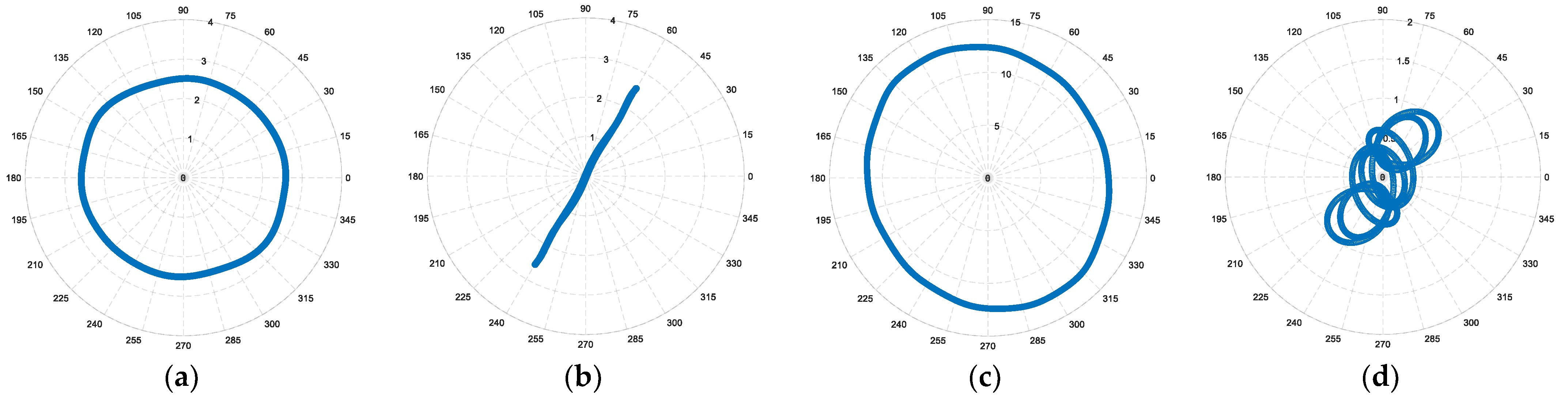
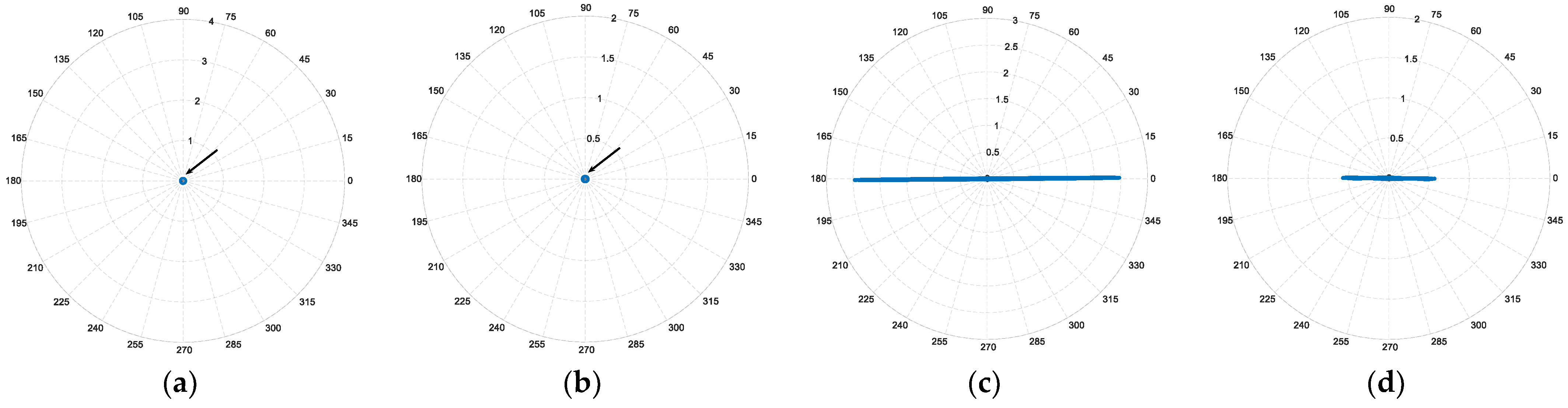
The loci of the current space vectors, evaluated in the first and fifth subspaces, are depicted in
Figure 5a,b, respectively. The resulting circular behavior of the current locus in the α
1-β
1 plane, and the null current value α
5-β
5 plane confirm the proper operation of the system. The corresponding voltage space vectors, evaluated in the first and fifth planes, are depicted in
Figure 5c,d, respectively.
Similarly, the voltage space vector in the α
1-β
1 plane exhibits a circular behavior, whereas small variations can be evidenced in the α
5-β
5 plane due to the small effect of the +5th and −7th harmonic components observed in
Figure 4d, and already established in [
35]. The loci derived from CSA and VSA reported in
Figure 5 are considered as a reference for the faulty phase cases.
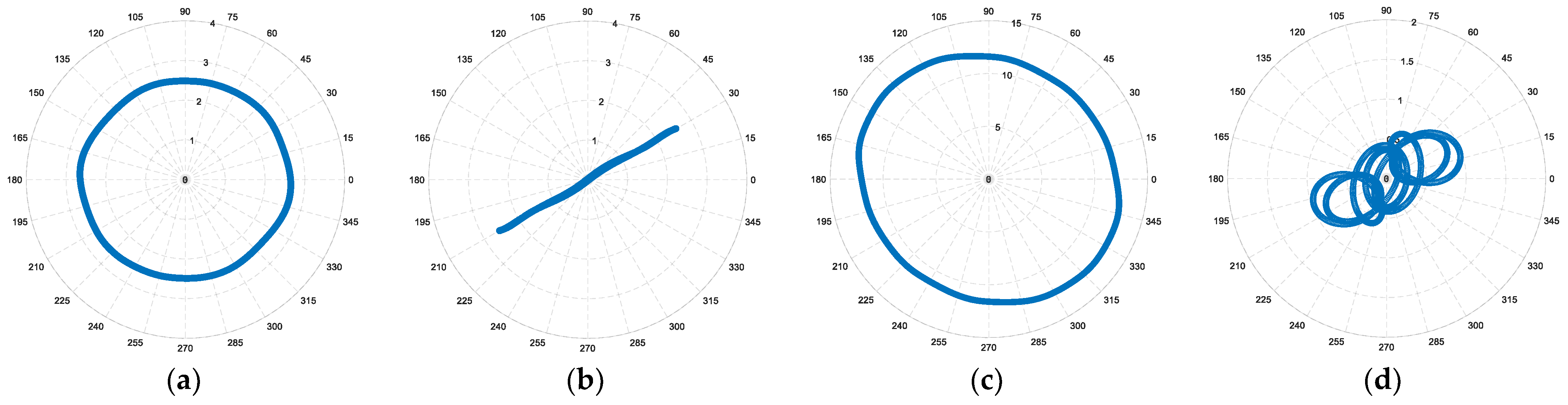
The behavior of the drive under the OPh fault in phase A1 is reported in
Figure 6. Under this fault condition, the current cannot flow through phase A1, leading to an evident current imbalance (
Figure 6).
Considering the reported spectra in
Figure 4 as references, the corresponding spectra under OPh faults in phase A1 (blue dotted line) and B1 (red solid line) have been computed and reported in
Figure 7.
Let us consider the spectra corresponding to the first OPh fault in phase A1 (blue dotted line). By comparing the spectra of
for the healthy (
Figure 4a) and faulty (
Figure 7a) conditions, the magnitude evolution of the inverse component at
−f is evident, which is classically expected in the α
1-β
1 plane, leading to a first spectral fault detection signature of the Oph fault. For the same fault condition, the spectrum of the space vector
, is depicted in (
Figure 7b). With reference to the healthy case (
Figure 4b), the relevant magnitude variation of the fault components at
±f are clearly evidenced, leading to a second more relevant spectral fault detection signature of the Oph fault.
In terms of VSA, the spectra of
v̅
S1,ref and
v̅
S5,ref are reported in
Figure 7c,d, respectively. Compared to the healthy case (
Figure 4c), the spectrum of
v̅
S1,ref shows an inverse component at
−f under the faulty condition (
Figure 7c), whereas the voltage space vector
v̅
S5,ref has shown a relevant magnitude variation of the fault components
±f. Considering the magnet pole arc design, the magnitudes of the 5th and 7th harmonics remain unchanged.
By comparing the spectra obtained in the healthy condition (
Figure 4) and those corresponding to an OPh fault in phase A1 (blue dotted line in
Figure 7), both CSA and VSA can be considered for OPh fault detection. However, by observing the similarities of the spectra obtained under OPh faults in phase A1 (blue dotted line) and B1 (red solid line), reported in
Figure 7, one can note that a possible solution for faulty phase identification cannot be based on the spectral analysis, even considering CSA or VSA.
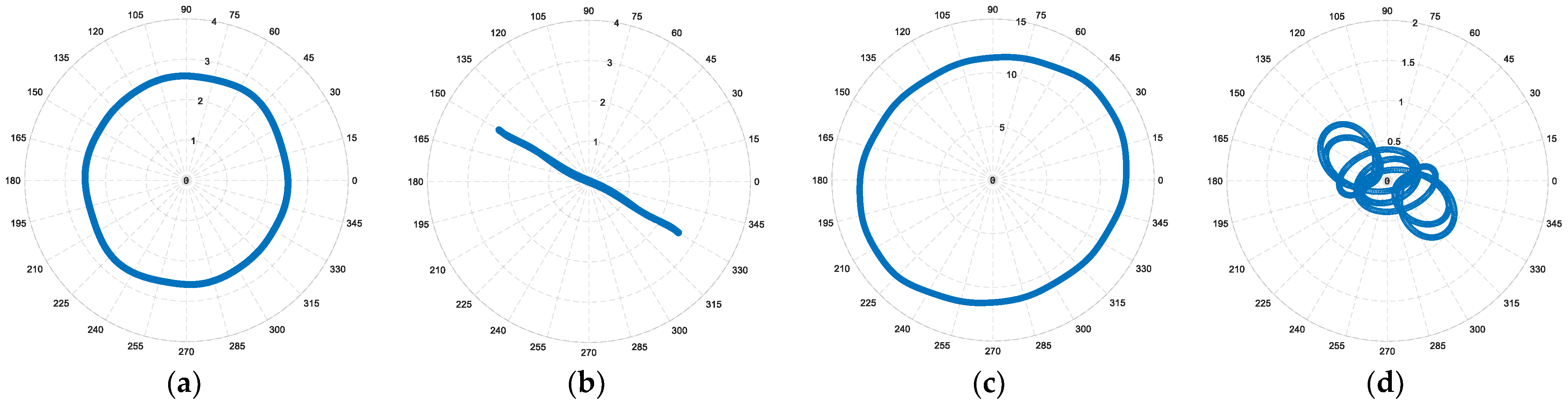
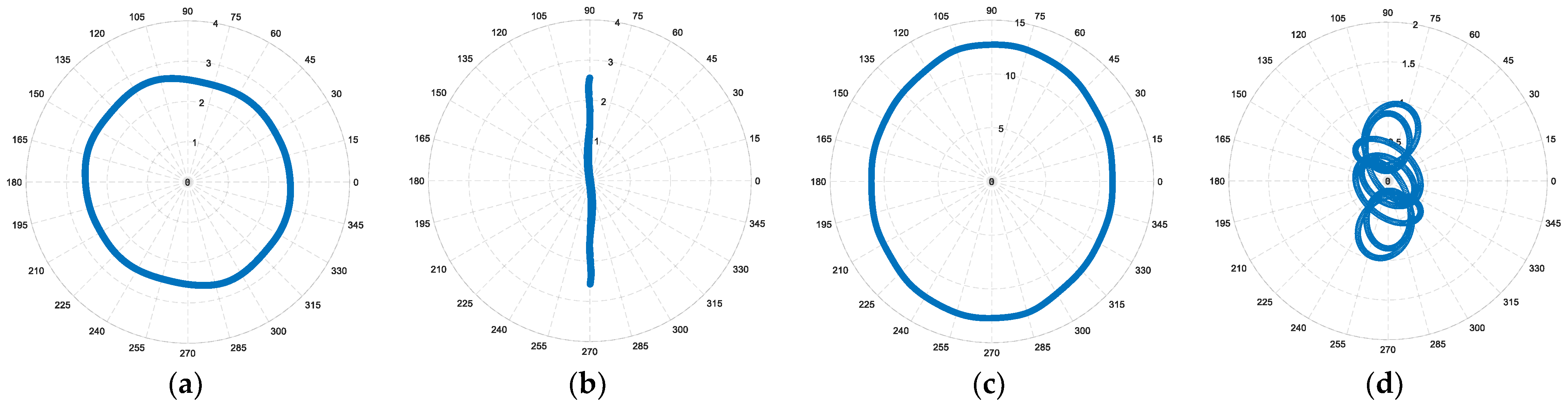
The current locus evaluated in the α
1-β
1 plane (
Figure 8a) shows a quasi-circular trajectory and does not show a particular shape when compared to the healthy condition (
Figure 5a). Nevertheless, when compared to the healthy case (
Figure 5b), the current space vector evaluated in the α
5-β
5 plane (
Figure 8b) indicates a significant variation, leading to a clear detection of the tested fault. Specifically, the current locus exhibits a particular orientation of 180° with the real axis, which corresponds to the direction of the phase A1 angle shown in
Table 2. The voltage space vectors, evaluated in the first and fifth planes, are reported in
Figure 8c,d. In the α
1-β
1 plane, the voltage locus does not change significantly, showing a particular shape corresponding to the introduced OPh fault. Conversely, when compared to the healthy case (
Figure 5d), the voltage space vector evaluated in the fifth plane shows a different shape due to the introduced OPh fault.
Due to the dominance of the fundamental component in the α1-β1 plane for both the current and voltage space vectors, the corresponding loci have shown a quasi-circular shape and then make the detection of an OPh fault difficult. As far as the current and voltage loci evaluated in the fifth plane are concerned, their relevant variations are useful for OPh fault detection.
In order to explore the feasibility of OPh fault localization through CSA and VSA, a series of simulations were performed considering different OPh fault configurations. The behavior of the drive, under the six OPh fault configurations, in terms of CSA and VSA evaluated in the first and fifth planes, are reported in
Figure 9,
Figure 10,
Figure 11,
Figure 12 and
Figure 13, respectively.
As a first comment, the very low sensitivity of CSA to an OPh fault, evaluated in the first plane, is confirmed by the reported loci in
Figure 9a,
Figure 10a,
Figure 11a,
Figure 12a,
Figure 13a, corresponding to the different configurations of an OPh fault, respectively. The same comment is valid for the results in terms of VSA, evaluated in the first plane, and reported in
Figure 9c,
Figure 10c,
Figure 11c,
Figure 12c,
Figure 13c.
The results reported in
Figure 9b,
Figure 10b,
Figure 11b,
Figure 12b,
Figure 13b are the current loci evaluated in the α
5-β
5 plane, where the current space vectors exhibit distinct orientations, relative to the real axis depending on the OPh fault location. With a less precise orientation, the same comment is also valid for the voltage space vectors, evaluated in the same subspace and reported in
Figure 9d,
Figure 10d,
Figure 11d,
Figure 12d,
Figure 13d, for the different OPh fault configurations, respectively. In
Table 2, obtained ideal directions of the current or voltage loci, evaluated in the α
5-β
5 plane, are shown.
Based on the current space vector direction, evaluated in the α
5-β
5 plane, OPh fault detection and localization are clearly evidenced. However, using the corresponding space vector in terms of VSA, due to the disturbing presence of the +5th and −7th harmonic components [
35], only OPh fault detection is possible.
To refine the accuracy of angle tracking through Current Space Analysis (CSA), and more importantly, to make possible the use of Voltage Space Analysis (VSA) for localizing an OPh fault, two diagnostic space vectors are proposed, which adeptly merge the isolated contributions of the ±1 fault harmonic components under the OPh fault condition.
A flowchart illustrating the proposed strategy with the computation of the diagnostic space vectors
and
, is shown in
Figure 14.
Due to the two independent neutral points of the stator windings, four current sensors are sufficient to determine the values of the six stator currents. By applying the MsVT transformation (1), the current space vector
is calculated. The space vector
is available in the control scheme at the output of the current regulators based on PI
+5 and PI
−7, as shown in
Figure 2. As can be seen in
Figure 14,
and
are then processed by some dedicated low-pass filters, implemented in reference frames synchronous with the fault harmonic components +1 and −1 in the α
5-β
5 plane.
In
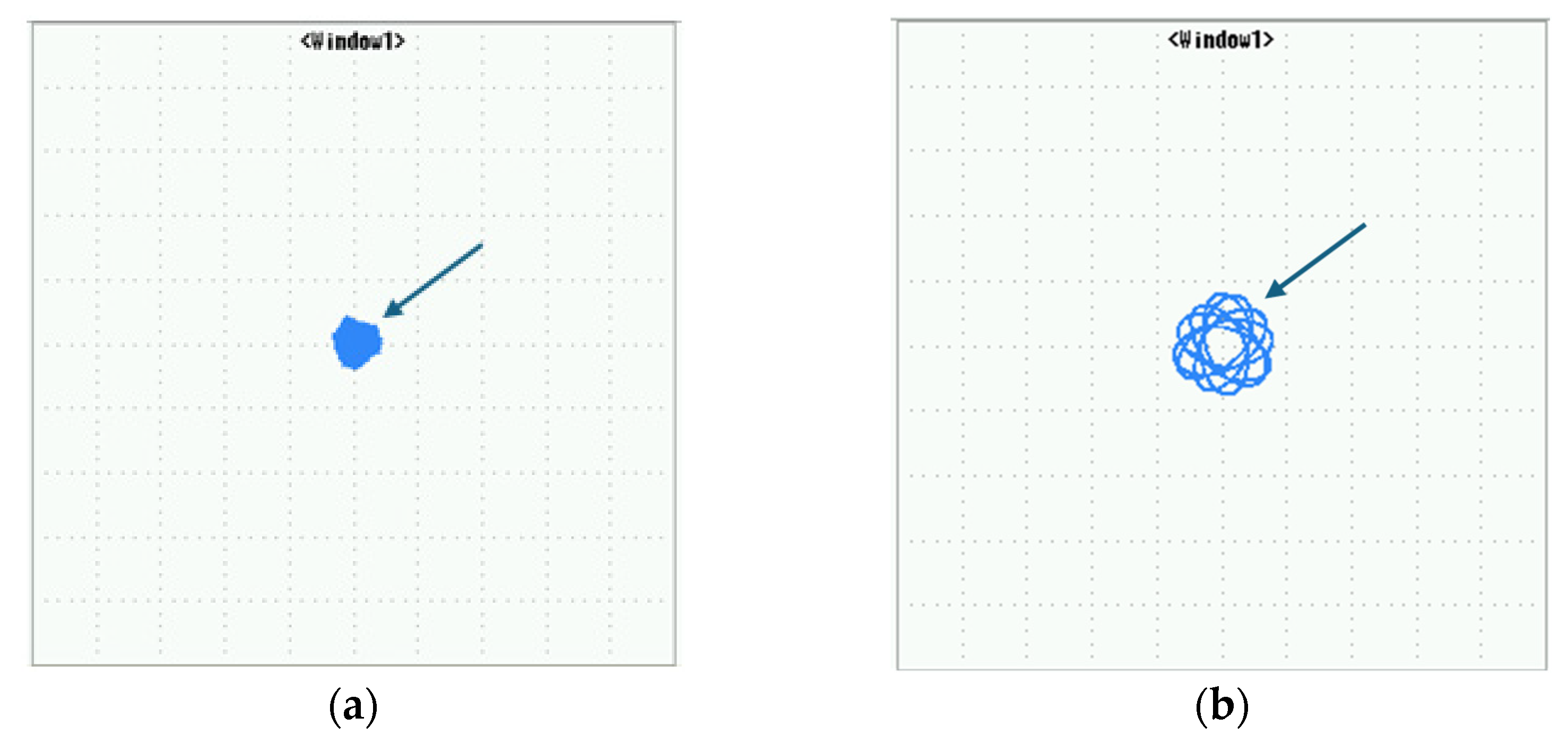
Figure 15, the behaviors of the proposed diagnostic space vector, under healthy and OPh fault conditions in phase A1, are reported.
In
Figure 15a,c, the behaviors of the diagnostic space vector
under healthy and OPh fault conditions in phase A1 are reported, respectively. Comparing the loci obtained from healthy to faulty conditions, it is evident that the detection and specifically the 0° orientation of the vector under faulty conditions (
Figure 15c) is slightly improved when compared to the current space vector
reported in
Figure 8b.
On the other hand, the results based on the diagnostic space vector
under healthy and OPh fault conditions in phase A1 are reported in
Figure 15b and d, respectively. Under the healthy condition, comparing the obtained zero value of vector
v̅
S5,±1, (
Figure 15b) to vector
v̅
S5,ref (
Figure 5d), it is evident that the detectability of the healthy case has been improved. More importantly, comparing the same quantities, reported in
Figure 8d and
Figure 15d, respectively, the 0° orientation of the vector
is clearly evidenced, which is in total agreement with the orientation of vector
, leading to an evident localization of the faulty phase A1.
4. Experimental Results
In order to validate the results obtained in simulations, a complete drive system has been installed in the Laboratory and some experimental tests have been performed. The setup consists of a six-phase MOSFET inverter and a 5.5 kW asymmetrical six-phase surface-mounted PMSM. The main parameters of the six-phase PMSM are indicated in
Table 1, where four poles, 48 slots, and double-layer, short pitch stator windings, having two slots per pole and per phase, are considered. Some pictures of the experimental bench are shown in
Figure 16, where a detailed schematic diagram of the built test bench is illustrated in
Figure 16c. The six-phase motor is coupled to a three-phase induction motor acting as the load. The FOC scheme of
Figure 2 was implemented in a TMS–320F2812-based electronic control board. Having 32-bit CPU, 150 MHz as the operating frequency, and a high-performance fixed-point DSP operation, the adopted control board meets the implementation requirements for the adopted control and the proposed associated diagnosis strategy. The accuracy of the current sensors is of ±1.5%, with a linearity of ±1.5%, and a frequency bandwidth of (−3 dB) 80 kHz. The encoder resolution is of 2048 pulses per revolution.
The VSI switching frequency is of 5.5 kHz with a deadtime of 3.2 µs, whereas a sampling rate of 5.0 kHz for the data acquisition and frequency domain analysis was adopted.
The performance of the six-phase drive was first assessed under healthy conditions and during steady-state conditions for a constant speed of 150 r/min and a torque setpoint of 5 Nm. The corresponding results are reported in
Figure 17,
Figure 18 and
Figure 19.
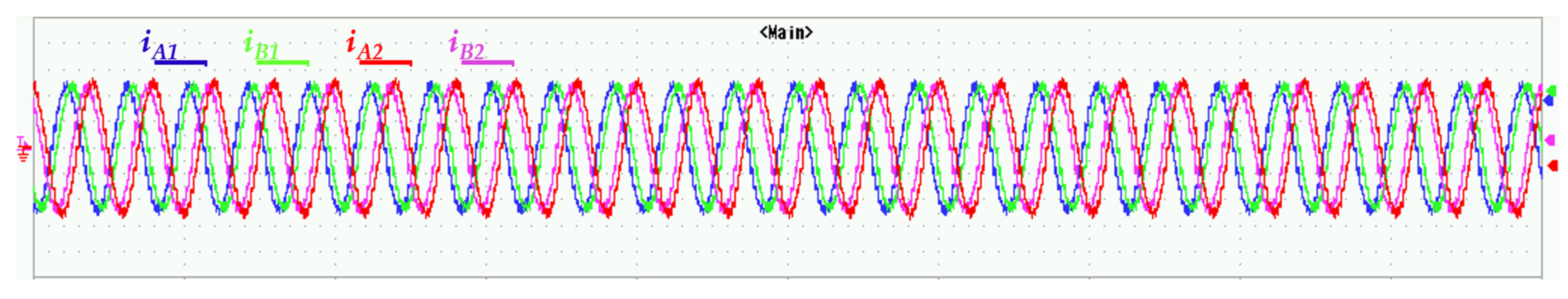
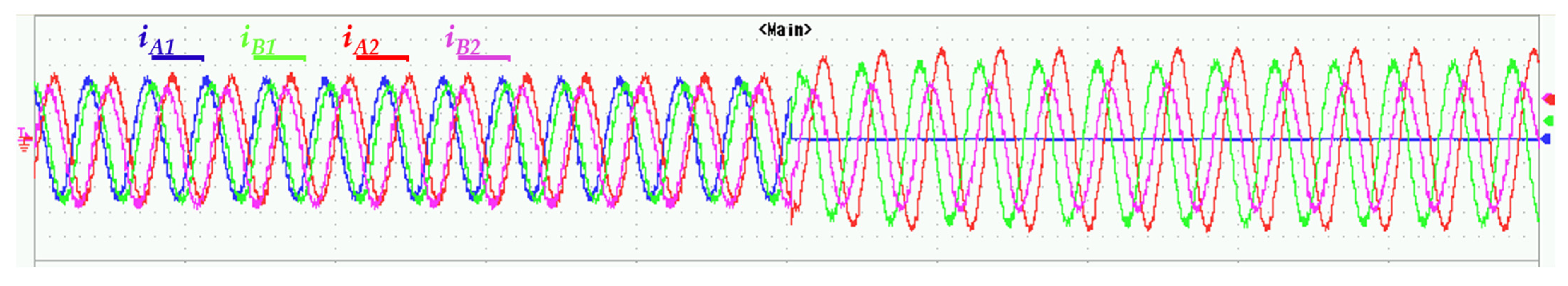
The stator currents of phases A1, B1, A2, and B2 are reported in
Figure 17. As can be seen, the stator currents are almost balanced and sinusoidal.
The corresponding current
and voltage
v̅
S5,ref space vectors, evaluated in the fifth plane, are depicted in
Figure 18a,b, respectively. As expected, due to the action of the current regulators (PI
+5 and PI
−7), the current locus shows a quasi-null value (
Figure 18a); the residual quantity observed on the figure is mainly due to noise and local disturbance effects. With reference to the voltage locus, the effects of the emfs harmonics are clearly shown (
Figure 18b), as anticipated in the previous sections. As can be seen, the obtained experimental current (
Figure 18a) and voltage (
Figure 18b) loci evaluated in the α
5-β
5 plane corroborate the Simulation Results (
Figure 5b,d), respectively, for the healthy machine.
It should be noted that the observed small disturbances for the current space vector are mainly due to the intrinsic manufacturing asymmetries of the motor, temperature effects, inverter nonlinearity (dead times and voltage drops on the switches), and current sensors tuning, which can affect the accuracy of the locus not only in healthy conditions, but also under the presence of OPh faults. It is worth noting that adding these disturbing effects to the presence of the 5th and 7th harmonics due to the magnet pole arc design will complicate further the use of the voltage space vector v̅S5,ref locus for detecting and localizing an OPh fault. These effects are expected to be eliminated using the proposed diagnostic space vector.
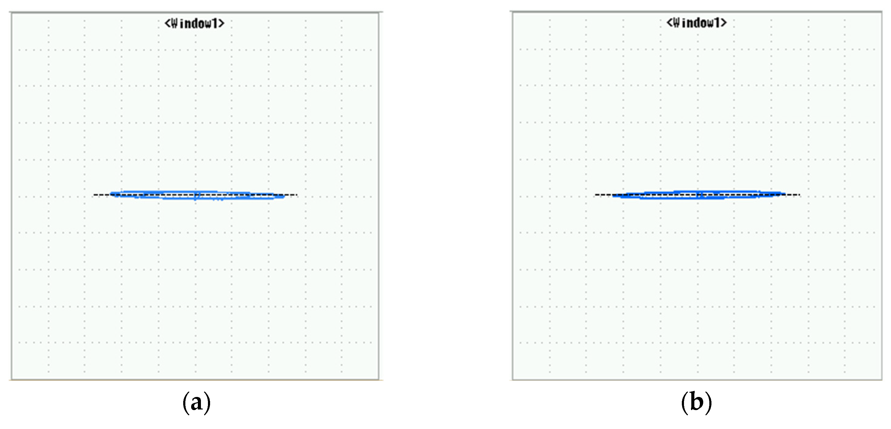
In
Figure 19, and under the same healthy operating conditions, the behaviors of the proposed diagnostic space vectors, in terms of the current and voltage, are reported, where clear zero current and voltage are evidenced. These experimental results corroborate the anticipated Simulation Results reported in
Figure 15 for the healthy case, which validate the performance of the proposed strategy.
Specifically, comparing the current loci of the space vectors
and
and represented in
Figure 18a and
Figure 19a, respectively, it is clear that the proposed diagnostic space vector
provides a high immunity against noise and the disturbing effects discussed above, leading to an accurate diagnosis of the healthy state of the machine, as
is practically equal to zero.
On the other hand, by comparing the voltage loci of the space vectors
v̅
S5 and
reported in
Figure 18b and
Figure 19b, respectively, one can note that the proposed diagnostic space vector
eliminates the disturbing effects of the 5th and 7th harmonics, leading to a clear detection of the healthy state of the machine, as
is practically equal to zero.
In order to assess the capability of CSA and VSA in detecting and localizing OPh faults, a series of tests have been performed.
In
Figure 20, the behavior of the six-phase drive is shown during a transition from a normal operation to an OPh fault in phase A1. During the test, the healthy conditions are maintained during the first 2.5 s, where the currents are quite balanced and sinusoidal. At t = 2.5 s, an OPh fault is applied in phase A1, where a null current value is evidenced, leading to an imbalance in the phase currents.
Current and voltage loci, evaluated in the α
5-β
5 plane, are depicted in
Figure 21a,b, respectively. As can be seen, the current locus in the α
5-β
5 plane (
Figure 21a) is different from zero and shows a vector orientation of 0° with respect to the real axis, as predicted by the Simulation Results (
Figure 8b), enabling the detection and localization of the OPh fault applied to phase A1. In terms of VSA, the voltage locus evaluated in the α
5-β
5 plane is depicted in
Figure 21b. When compared to the reference voltage locus of
Figure 19b, the voltage space vector changes significantly in the presence of the fault, as anticipated by the simulation (
Figure 8d), leading to an evident detection of the fault, whereas the localization of the opened phase based on a clear angular orientation remains difficult.
For the same operating condition, a second test was carried out under an OPh fault in phase B1, where the obtained current and voltage loci, evaluated in the α
5-β
5 plane, are depicted in
Figure 22a,b, respectively. As can be seen, current and voltage paths in the α
5-β
5 plane (
Figure 22a) reveals a distinct orientation of 60° with respect to the real axis, enabling the detection and localization of the Oph fault in phase B1. It is worth noting that the difficulty of interpretation for detection and, more importantly, localization purposes observed for the voltage space vector
v̅
S5,ref under the OPh fault in phase A1 (
Figure 21b) are also valid for this second faulty case (OPh-B1). After several experiments, it should be noted that the same difficulties have been observed for the remaining faulty phase cases.
The loci of the diagnostic space vector, under the OPh fault in phase A1 and B1, are reported in
Figure 23 and
Figure 24, respectively.
When examining the reported current loci in
Figure 23a and
Figure 24a, using the proposed diagnostic space vector
, with reference to those obtained using
reported in
Figure 21a and
Figure 22a, respectively, the improvements in terms of the angular orientation accuracy are evident, leading to a more accurate OPh fault localization.
In terms of VSA, by comparing the loci reported in
Figure 23b and
Figure 24b to those reported in
Figure 21b and
Figure 22b, one comes to the conclusion that based on the proposed diagnostic voltage space vector
, an accurate detection and localization of an OPh fault is validated.


