1. Introduction
Topology optimization (TO) has emerged as a powerful tool for designing liquid-cooled heat sinks, offering improved thermal performance and reduced energy consumption. Several recent studies have advanced the field by focusing on multi-objective optimization, experimental validation, and practical applications [
1,
2,
3].
Li et al. [
4] developed a TO-based design method to balance fluid power dissipation and heat transfer maximization. Using COMSOL Multiphysics 5.3a, they generated cooling channels optimized for both uniform and non-uniform heat sources, producing Pareto optimal solutions. Their experimental validation showed that TO designs achieved lower thermal resistance and higher Nusselt numbers compared to conventional parallel channels, highlighting their efficiency in managing heat flux. In another study, Li et al. [
5] explored flow distribution and heat exchange optimization under engineering constraints. Their findings demonstrated that flow-optimized designs minimize hydraulic resistance, while heat exchange optimized layouts reduce thermal resistance and peak temperatures, enhancing performance across different cooling scenarios.
Xia et al. [
6] explored the impact of inlet and outlet configurations on heat sink efficiency using density-based TO. Their findings indicated that well-distributed fluid flow significantly enhances thermal performance, while higher solid thermal conductivity results in less winding channel layouts. Similarly, Wang et al. [
7] employed TO to compare different inlet and outlet arrangements, aiming to minimize both the average solid temperature and power consumption. Their results demonstrated that the optimized configurations improved heat transfer performance compared to the horizontal rib inlet and outlet liquid-cooled plate-type microchannel heat sink. Following a similar approach, Huang et al. [
8] introduced a novel pseudo-3D TO model tailored for chip heat sink designs. They applied this model to optimize heat sink structures across various inlet and outlet configurations, conducting detailed numerical experiments to evaluate thermal performance under realistic conditions. The results validated the effectiveness and reliability of the pseudo-3D TO model.
Additionally, Zhao et al. [
9] introduced a computationally efficient TO method based on the Darcy model and validated its designs with turbulence models. Their work demonstrated the ability to create manufacturable channels with competitive thermal performance.
Lee et al. [
10] addressed challenges associated with TO porous regions by incorporating cylindrical pin-fin structures and metal foams, which were experimentally validated. This innovative approach enhanced both heat transfer and manufacturability, overcoming a key limitation of conventional TO designs. Similarly, Joo et al. [
11] explored the use of porous media by applying thermofluid TO to forced convection air-cooled heat sinks integrated with graphene aerogel to improve heat dissipation. They analyzed the impact of the aerogel’s thermal and transport properties on heat sink performance, concluding that incorporating graphene aerogel reduced thermal resistance compared to optimized heat sinks without aerogel.
Yan et al. [
12] optimized nine heat sink designs using density-based TO and fabricated them via laser powder bed fusion. A CFD model was developed to analyze temperature distribution around different fins. Both numerical and experimental results confirmed that TO fins significantly improve heat transfer efficiency.
In recent years, the research field of data-based TO methodologies to complement conventional TO methodologies with computation cost constraints and limitations due to their inherent iterative nature has been thriving [
13,
14]. Amongst the data-driven based solutions, machine learning (ML) and artificial intelligence (AI) based solutions have been gaining interest in the TO field, aiming to provide suitable solutions to different TO challenges, among them [
15]: acceleration of iteration, non-iterative optimization, metamodeling, dimensionality reduction of design space, improvement of optimizer, generative design (design exploration), and postprocessing.
Much of the effort and work are focused on meta-modeling, training ML solutions to estimate key output parameters and thus reduce the required computation time of traditional TO methodologies. This line of work directly tackles several of the previously mentioned challenges. Towsyfyan et al. [
16] trained an artificial neural network (ANN) to predict base temperature and pressure drop for a plate-fin heatsink. Parallelly, Lu et al. [
17] follow a similar approach, training a neural network to predict two key outputs parameters (Nu and ΔP) and then using genetic algorithms to explore and optimize the design of the heat sink with good results.
Gaymann and Montomoli [
18] explore the concept of making the fluid-structure TO a gamification problem by combining deep neural networks and Monte Carlo tree search for minimizing pressure difference.
The collective advancements in TO demonstrate its potential to generate high-performance cooling solutions. Studies have shown that TO can enhance heat transfer efficiency, improve manufacturability, and integrate advanced materials [
19,
20,
21,
22]. However, despite these developments, research on TO for thermal management remains limited, and further studies are necessary to refine optimization methods, validate designs experimentally, and explore broader practical applications [
23,
24]. To address this gap, this paper aims to further contribute to the research by analyzing a novel approach by using hybrid CFD and a Monte Carlo-driven methodology for heat sink design optimization. The study covers the whole chain, from design to manufacturing, including an experimental validation of simulation and optimization results. By tackling these challenges, we seek to advance the adoption of TO designs in thermal management applications.
2. Methodology
This study integrates numerical simulations in Ansys Fluent 2023 R1 with data-driven algorithms using a Monte Carlo approach. A custom-developed interconnection methodology is designed to bridge these components, complemented by an experimental setup to validate the methodology.
2.1. Numerical Simulation
2.1.1. Geometry and Concept
In this study, liquid-cooled channels embedded in heat sinks are designed by a TO method combining CFD, thermal simulations, and optimization algorithms to maximize the heat exchange between the fluid and the heated plate and thus be able to reduce as much as possible the temperature of the heated plate. Additionally, the resulting TO geometry is compared to a traditional serpentine design, in terms of temperature as well as pressure loss, which translates to power required to pump the cooling fluid.
The design is modeled as a series of porous domains, where during the optimization process the design variable (porosity) continuously varies from zero (solid) to one (fluid) to define the final channel shape.
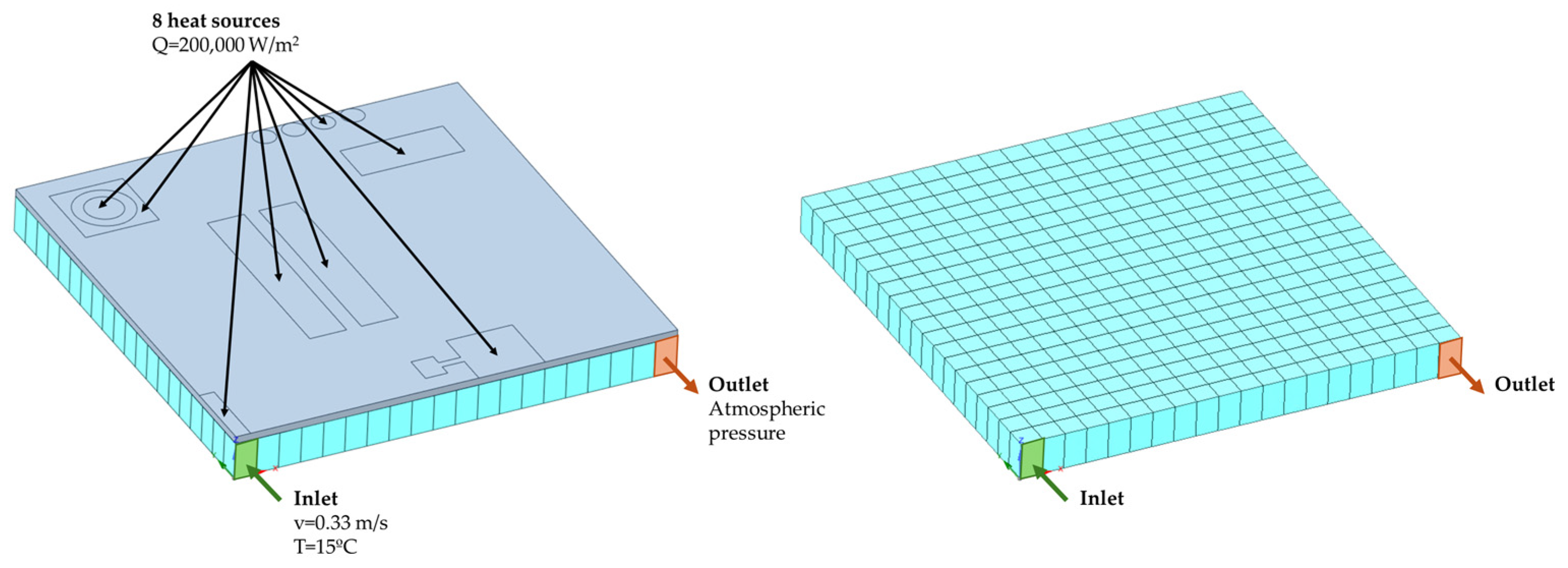
The grey region on
Figure 1 corresponds to the heated plate, where 8 heat sources of different shapes and sizes are defined. Similarly, the cyan region is formed by 20 × 20 smaller domains that can change their identity from fluid to solid, or the other way around, at each optimization iteration. If the domain is considered solid,
whilst if the domain is considered fluid,
where
is the inverse permeability of the porous medium.
2.1.2. Mesh
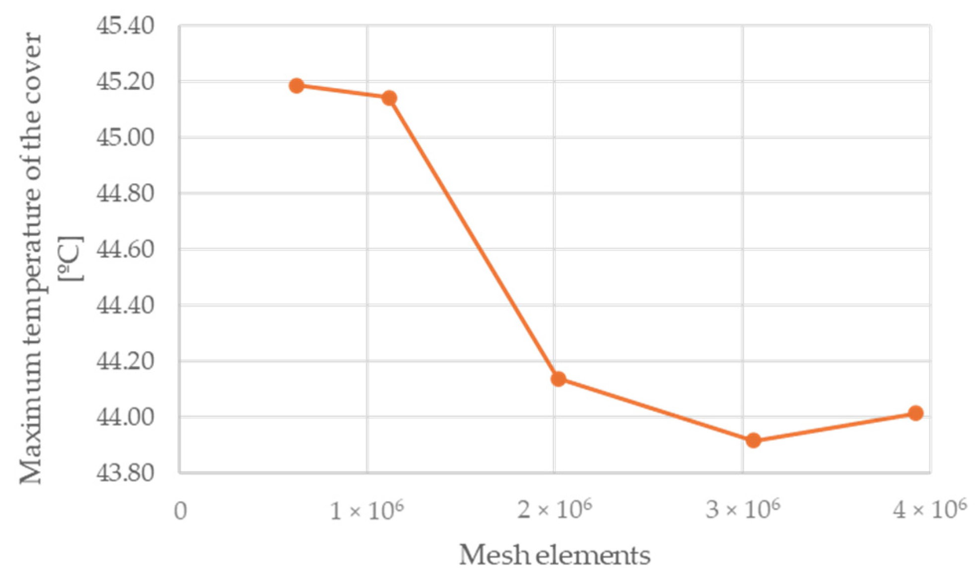
The 3D geometry is imported into the Ansys Workbench Mesher to be discretized into small computational elements. To ensure mesh independence, five different mesh configurations are tested for the serpentine circuit, each with a varying number of tetrahedral elements: 622,897, 1,116,735, 2,016,144, 3,058,923, and 3,920,605, as illustrated in
Figure 2. A comparison of the maximum temperature of the heated surface between the course (622,897 elements) and finest (3,920,605 elements) meshes yields a relative error of approximately 2.66%. Additionally, the calculation times for these two meshes are 1.42 and 8.08 min, respectively.
As discussed in subsequent sections, achieving fast simulation times is essential to allow for the high number of iterations required by the Monte Carlo-driven optimization process. Furthermore, given the need for reinterpretation of the algorithm-derived results, which will slightly modify the achieved temperature (as detailed in
Section 2.2), it is concluded that the mesh with 622,897 elements provides a suitable balance between accuracy and computational efficiency for further simulations.
2.1.3. Governing Equations
To simulate the multiphysical phenomena, Ansys Fluent 2023 R1 software is used to solve both the fluid flow equations as well as the energy performance of the cooling plate, considering the porous media concept for solid and fluid areas described previously.
The mathematical formulation of the laminar fluid flow and heat transfer models used in this work is discussed here. The full Navier-Stokes equations [
25,
26,
27], governed by the momentum and continuity equations, are expressed as follows:
where
represents the fluid density,
and
denotes the velocity and pressure fields, respectively,
is the fluid’s dynamic viscosity, and
represents the fluid body forces.
For a steady-state flow of an incompressible Newtonian fluid, where inertial effects are negligible, the governing equations are:
To describe solid regions, a mixed model for fluid flow through a porous medium, known as Darcy’s law, is applied [
25,
26]:
where
is the inverse permeability of the porous medium.
The fundamental concept behind using a porous media model is to regulate material permeability so that setting it to zero simulates solid behavior. In this limit, the fluid velocity in the corresponding region approaches zero.
The fluid flow equation and Darcy’s law are integrated using the Brinkman equations [
26,
28], which enable both models to be incorporated into a single system of equations:
The Brinkman equations provide a unified framework for representing both solid and fluid regions within a domain, which can dynamically evolve during the optimization process. The term
functions as a permeability control parameter, enabling the formation of zero-permeability zones that effectively absorb velocity and enforce a no-flow condition. Conversely, in regions with high permeability, the standard fluid flow equations dominate, governing the fluid dynamics [
25]. The inverse permeability acts as a fluid resistance, allowing a higher or lower fluid flow through a determined region. This approach allows the design domain to transition between solid and fluid states as needed.
The energy equation describes the heat transfer for a material subjected to both heat conduction and convection, considering the flow over the domain:
where
represents the temperature field. The conduction term is governed by the material’s thermal conductivity (
), while the convective term depends on the fluid velocity (
) and specific heat (
). This model also assumes a steady-state condition, meaning
.
2.1.4. Boundary Conditions and Material Properties
The boundary conditions consist of an inlet and an outlet for the refrigeration circuit. The inlet conditions are defined as a velocity of 0.33 m/s and a temperature of 15 °C, while the outlet is maintained at atmospheric pressure. A uniform heat flux of 200,000 W/m2 is applied to the eight heat source surfaces.
Regarding materials, the optimization domain, which forms the base of the circuit, is composed of stainless steel in solid regions and water in fluid regions, while the circuit cover is made of aluminum.
For the experimental validation simulation, additional materials have been incorporated to meet the manufacturing requirements of the prototype. These include silicone, used as a gasket to ensure water tightness; thermal paste, applied to improve thermal contact between the heating block and the aluminum cover; a copper heating block containing resistances to generate heat; and an epoxy interface, acting as an insulator to ensure that heat is only transferred to the designated heat source areas. Further details regarding the prototype are provided in
Section 2.4, and material properties are described in
Table 1.
2.1.5. Solver Setup
Simulations are performed on a computing server equipped with 2 Intel Xeon CPU E5-2620 v4 processors and 128 GB of RAM. Each simulation utilizes 4 cores and reaches convergence for a single iteration in about 2 min, as explained in
Section 2.3. The simulations use first-order upwind spatial discretization for flow parameters and second-order upwind for the remaining parameters, as well as the coupled pressure–velocity coupling scheme.
2.2. Data-Driven Design Optimization Protocol
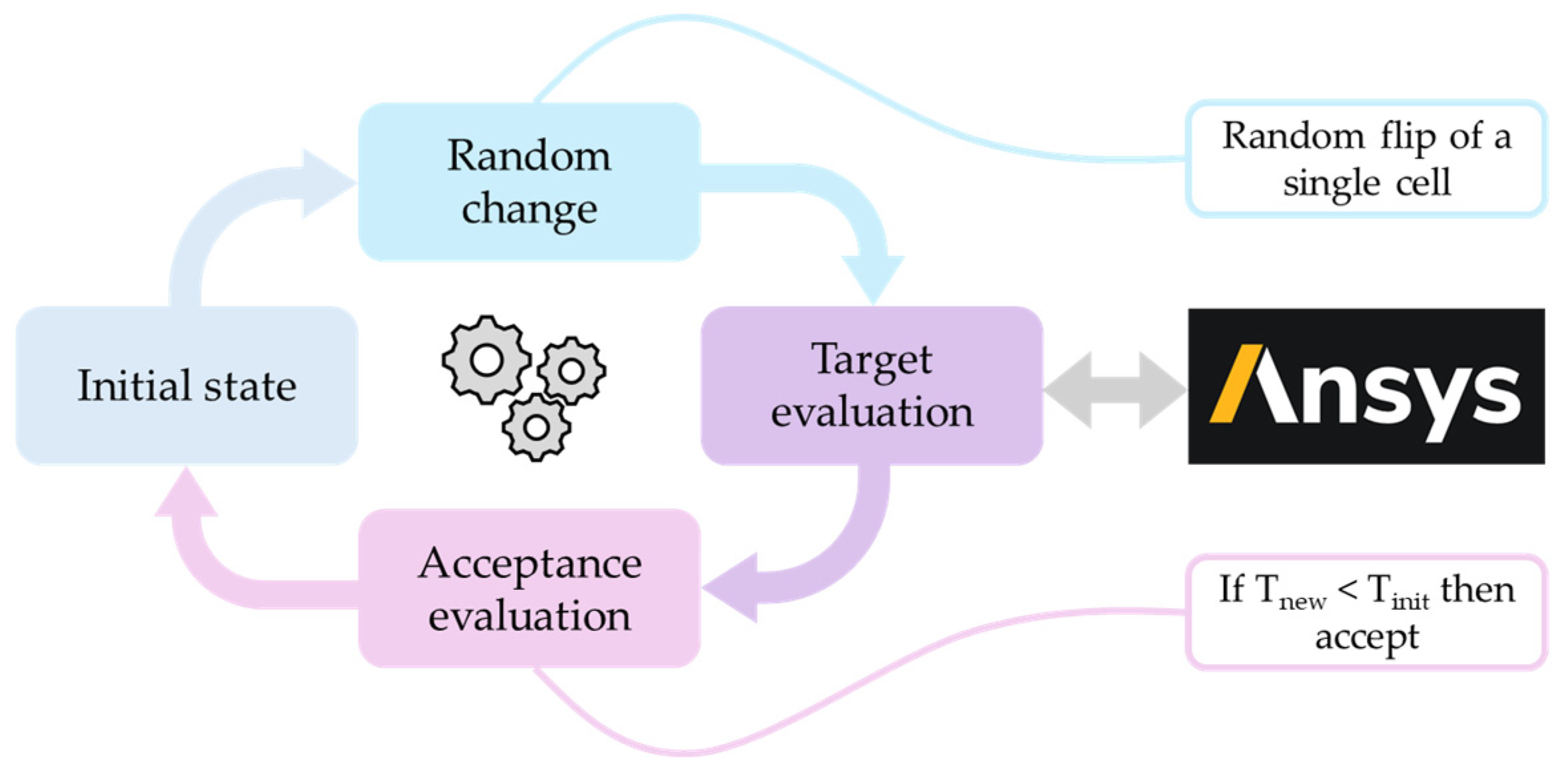
One of the main challenges for TO is the design of a methodology capable of simplifying the problem yet maintaining the nuances and boundaries governing the system. To this end, a methodology based on the discretization of the action space coupled with a Monte Carlo process optimization strategy is presented (
Figure 3).
The first step is the discretization into a finite number of domains of the initial circuit plate. The objective then is to optimize the porosity of each cell in a binary setup: solid or liquid. Subsequently the optimization process generates new design candidates to be validated within the simulation environment. This process is repeated iteratively until a convergence point is met. Finally, a post-processing stage is necessary to adapt these circuits to manufacturable prototypes.
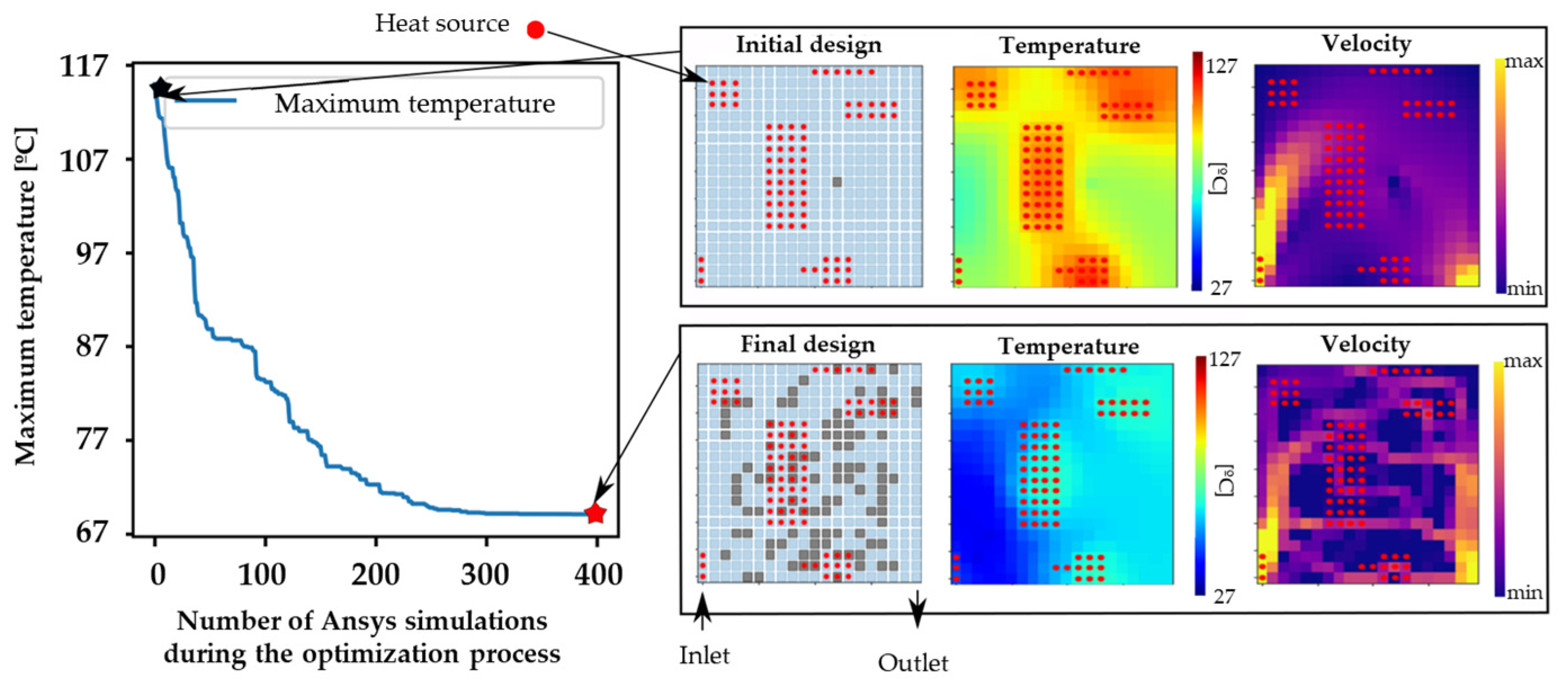
A set of restrictions is introduced. At each step, only one cell of the plate can be flipped between solid/liquid. This targets two main objectives: first, coherence between iterations, and second, speeding up the computation within the simulation software building upon prior cycle results. Once the simulation for the new design is completed, an evaluation is carried out to determine whether the changes are accepted or not. If the maximum temperature is lower than the result of the previous iteration, the change in design is accepted, if not, another modification of the previous cycle design is performed. This iterative process generates a series of changes that alter the design and decrease the temperature until it converges. An example of the result can be seen in
Figure 4, where the scaling of the proposed solution is shown, according to the multiple heat sources and geometry described in
Section 2.1.1 and
Figure 1, where grey squares correspond to solid domains and blue squared to fluid ones.
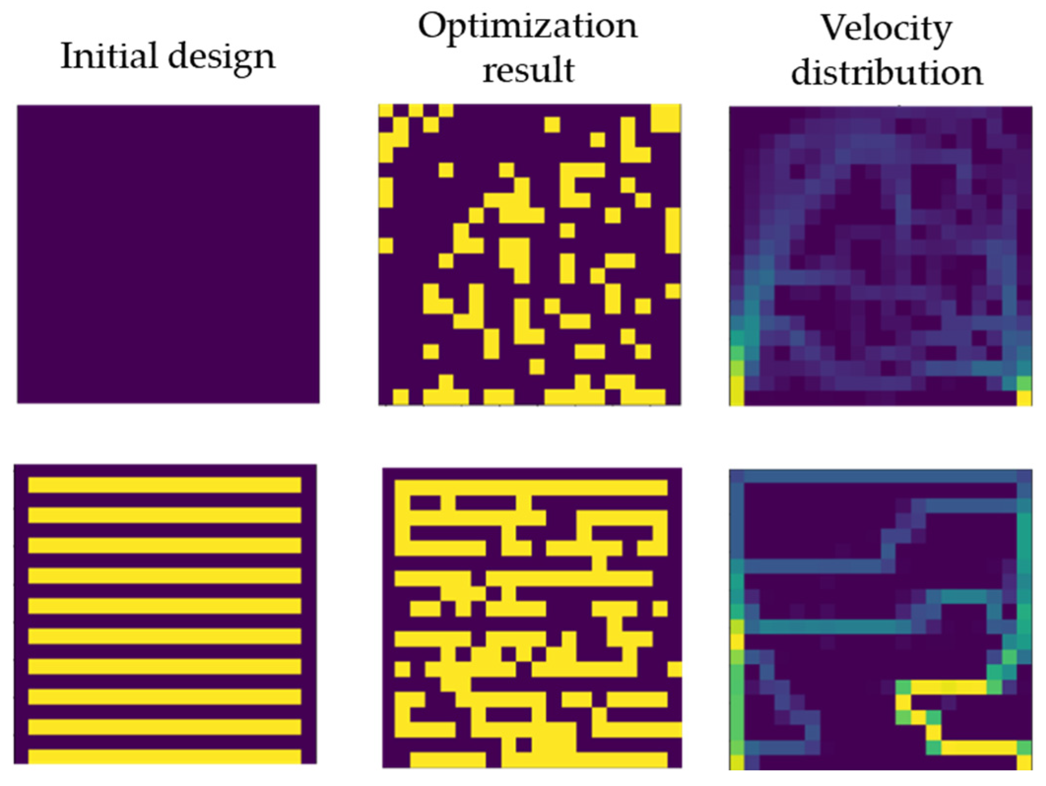
As can be seen in
Figure 4, the proposed optimization methodology converges relatively quickly. Nevertheless, it must be considered that the proposed strategy is a convex optimization method, which means that it will only converge to the nearest local minimum. At the same time, the method used has some limitations related to the changes introduced in the circuit (random 1-on-1 changes). This inherently implies that it is unlikely that the algorithm will generate very complex circuits. These two limitations may hinder its performance. To mitigate these limitations, the impact of initial states on the final design has also been studied (
Figure 5), leading to different designs that will be considered in
Section 3.
After performing the optimization using the data-driven optimization algorithm, the resulting designs exhibit a highly structured, grid-like pattern with sharp corners. This characteristic arises from the use of rectangular computational domains in the optimization process. Consequently, a post-processing reinterpretation of the results is required to ensure feasibility for machined manufacturing.
During this reinterpretation, regions identified with fluid-equivalent porosity are redefined as pure fluid (without porosity), while regions with solid-equivalent porosity are redefined as fully solid. As a result, the continuous transition of porosity between fluid-like and solid-like domains is eliminated, leading to the formation of a distinct solid-fluid interface.
2.3. Implementation: Simulation and Algorithm Interconnect
To facilitate communication between the Ansys Fluent software and the data-driven algorithm, a structured communication strategy has been implemented. This strategy involves executing simulations in Fluent’s background mode, wherein porosity values are modified, and results are extracted using text files that the optimization algorithm can process.
Given the need for extensive iterative evaluations to identify the optimal configuration based on the algorithm’s criteria, it is crucial to ensure that simulations are executed with maximal efficiency. Reducing computational time is essential to enhance the feasibility of running a large number of iterations within a reasonable timeframe.
Two complementary approaches have been implemented to minimize computational time: one focused on pre-processing in Fluent and the other on the calculation strategy.
In terms of pre-processing, it is necessary to generate the base case for optimization. While this study focuses on a single case, the methodology has been designed to be adaptable to various cases, ensuring broader applicability. Manually inputting all conditions into the software is a time-intensive process; therefore, automation techniques have been employed to accelerate this step. As a result, the pre-processing time has been significantly reduced from 2 h and 30 min to 25 min.
The second optimization strategy focuses on reducing calculation time. This approach involves establishing a direct connection between Ansys Fluent and Python 3.8, allowing the case to be loaded only once at the beginning of the process. All subsequent modifications dictated by the algorithm are then executed within the Fluent infrastructure, eliminating the need for repeated file handling. These modifications primarily involve adjusting porosity within the computational domains and extracting key output parameters, such as temperature, velocity, and pressure loss.
This strategy has led to a significant reduction in computation time, from 50 min to just 2 min per iteration, enabling the execution of the large number of iterations required for the optimization process to achieve optimal results.
Furthermore, the algorithm incorporates a mechanism to eliminate redundant calculations, further enhancing computational efficiency.
2.4. Experimental Setup
Two experimental setups have been constructed to validate the simulation results. One setup consists of the serpentine cooling channel design, and the other consists of the optimized cooling channel design, which gives better results.
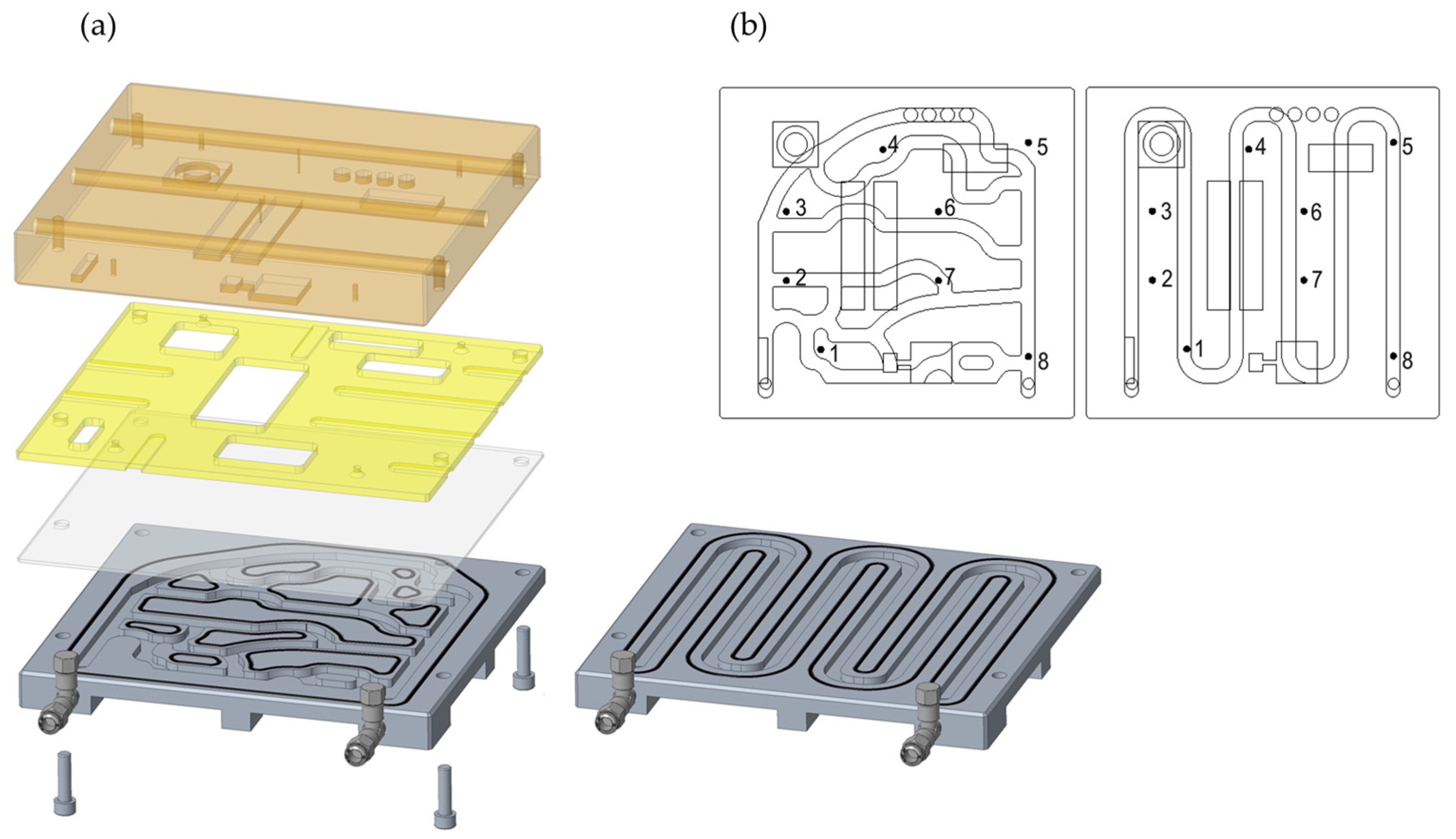
Figure 6a shows an exploded view of the manufactured model. 316 stainless steel blocks have been machined with the cooling channel pattern for each case. Grooves for rubber seals and threaded holes for water fittings are also machined into this block. Temperature measurements of the water inlet and outlet using K-type thermocouples have been added to the assembly. A water flow regulator to set water flow rate has also been added. Over this part, a 2 mm aluminum plate has been mounted. K-type thermocouples have been attached to this plate to measure the temperature at 8 control points (
Figure 6b). A copper block, machined with the pattern of the heat sources proposed, is used as a heat source body. Up to 6 cartridge heaters, 150 W each, are installed inside the copper block using lateral bores to heat it, and 2 K-type thermocouples are installed to measure the block temperature. Thermally conductive paste is used in the contact regions between the copper block and the aluminum plate to ensure homogeneous thermal contact. An epoxy fiberglass insulating plate is installed in between the copper block and the aluminum plate at the regions with no contact between them.
Figure 7 shows the arrangement of the experimental setup. Eurotherm Nanodac temperature controller is used to power control of the cartridge heaters in the copper block to achieve a stable temperature of 50 °C. All temperature data is acquired until the system achieves a steady state using National Instrument cDAQ-9172 with NI-9213 thermocouple input modules.
3. Results and Discussion
As discussed in
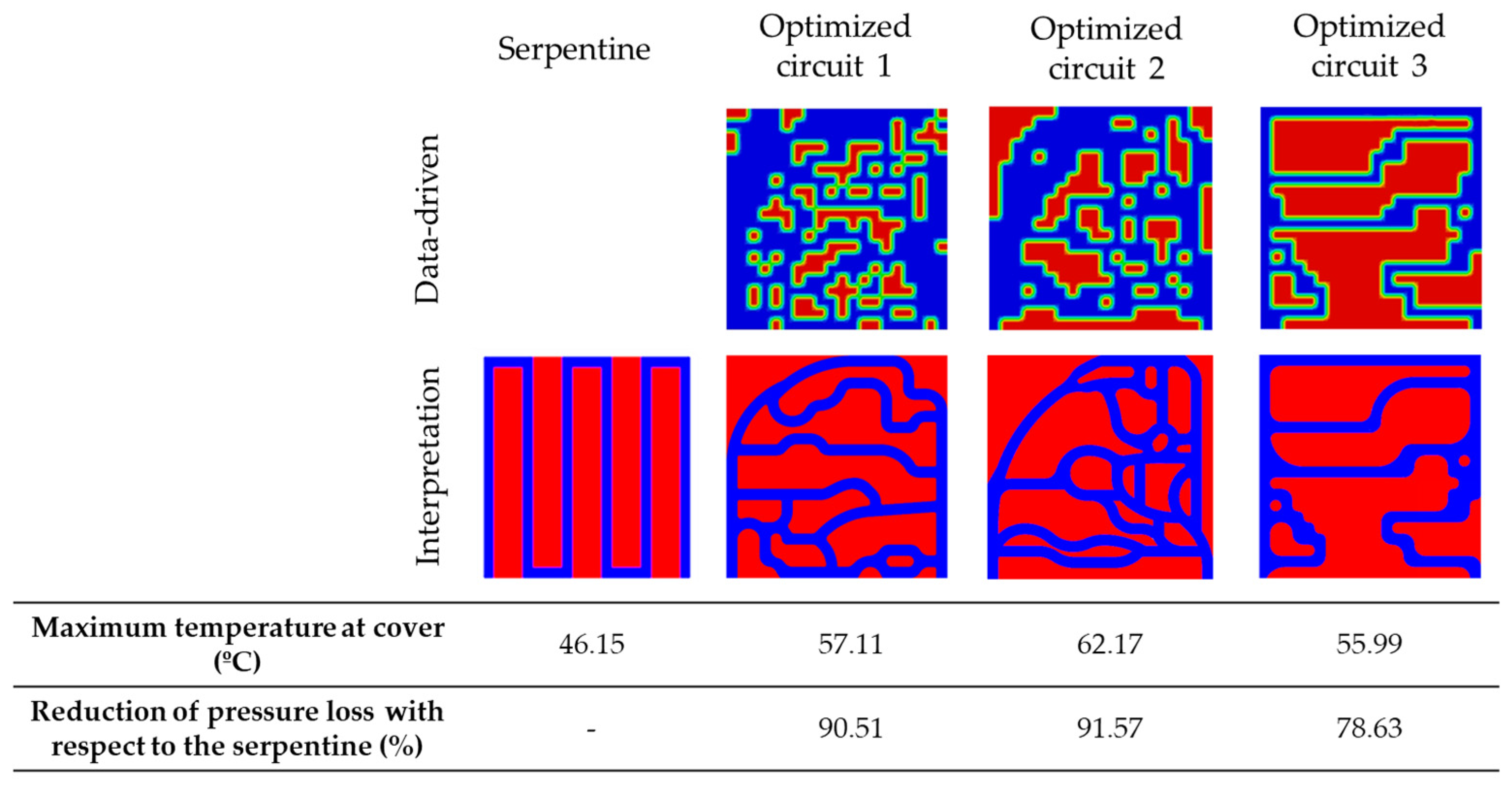
Section 2.2, the optimization algorithm is inherently limited to identifying local minimums rather than a global minimum. Consequently, applying different constraints—which either increase or reduce the algorithm’s degree of freedom—leads to the generation of different optimized circuit designs, as shown in
Figure 8.
The serpentine reference circuit is able to achieve a maximum temperature at the cover of 46.15 °C, whereas the simulation results indicate that the maximum temperature for the three optimized circuit designs is 57.11 °C, 62.17 °C, and 55.99 °C, respectively. While the optimized solutions exhibit slightly higher temperatures compared to the serpentine circuit, they offer a significant advantage in pressure loss reduction. Specifically, the optimized designs achieve reductions of 90.51%, 91.57%, and 78.63%, respectively, leading to substantially lower energy consumption.
This improvement in energy efficiency means that the optimized circuits require much less power to operate, resulting in both cost savings and a more sustainable cooling system. Furthermore, since this comparison is conducted at the same inlet velocity, the substantial decrease in pressure loss suggests that the water mass flow rate could be increased in the optimized circuits, potentially lowering the maximum temperature at the aluminum cover.
To further support this point, two additional simulations were performed by increasing the inlet velocity. At an inlet velocity of 0.36 m/s (a 9.53% increase), the optimized design achieves a heat extraction almost equal to that of the serpentine, 3.38% higher (780.11 W compared to 754.65 W), while still maintaining a 77.22% reduction in pressure drop. When the inlet velocity is further increased to 0.44 m/s (a 31.44% increase), the heat dissipation improves by 14.52% (864.22 W), with the pressure drop still remaining 68.55% lower than that of the serpentine. These additional simulations reinforce the effectiveness and practical relevance of the proposed methodology.
Among the three optimized circuit designs, optimized circuit 1 has been selected as it achieves the best balance between temperature reduction and pressure loss minimization. As detailed in
Section 2.4, both the serpentine circuit and the optimized circuit 1 have been manufactured for experimental testing to validate the simulation model and confirm the conclusions drawn from the study. As the manufactured part has suffered small alterations in order to ensure its manufacturability and assembly, the simulation has been repeated considering the new geometries, using the same criteria and conditions as before.
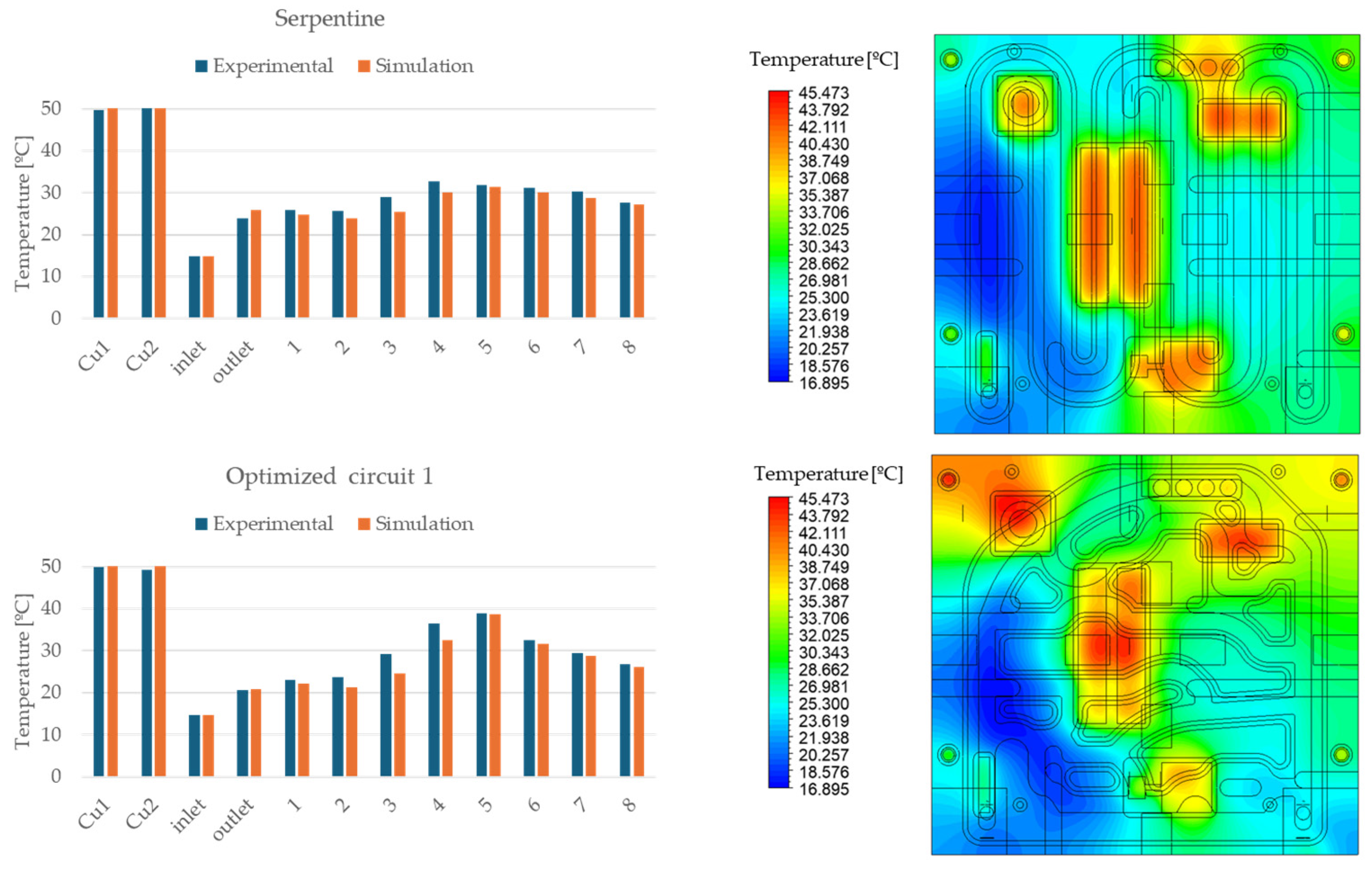
Figure 9 presents a temperature comparison between the experimental and simulation results for both the serpentine and optimized circuit 1. The close agreement between the measured temperatures at each sensor, whose location is indicated on
Figure 6, and the corresponding virtual sensor in the simulation confirms the accuracy and reliability of the simulation model.
This validation reinforces the robustness of the conclusions drawn from the simulation. While the maximum temperature at the aluminum cover in the optimized circuit is slightly higher, with an average of 29.27 °C for the serpentine circuit and 30.03 °C for optimized circuit 1, the significant reduction in pressure loss observed in the simulation leads to a notable decrease in the required pumping power. This results in a more energy-efficient and cost-effective cooling solution, demonstrating the advantages of the data-driven optimized design and the methodology proposed.
4. Conclusions
This study proposes a novel hybrid methodology for the TO of heat sinks, combining computational fluid dynamics (CFD) simulations conducted in Ansys Fluent with a Monte Carlo-based optimization framework. The approach is based on adjusting the porosity of discretized domains within a cooling circuit to iteratively evolve toward optimal channel configurations. By modeling the system as a porous medium with variable porosity, the optimization algorithm iteratively refines the design through binary evaluations of solid or fluid cells, leading to efficient thermal performance.
The methodology successfully converges to optimized solutions, although with some limitations inherent to convex optimization strategies, such as susceptibility to local minimums and reduced capacity to explore highly complex topologies. Nevertheless, the proposed approach enables practical and efficient cooling designs with substantial improvements in hydraulic performance. Among the three evaluated optimized designs, maximum temperatures reached are 57.11 °C, 62.17 °C, and 55.99 °C, compared to 46.15 °C for the reference serpentine channel. Despite the slightly higher temperatures, they offer substantial reductions in pressure loss, by 90.51%, 91.57%, and 78.63%, respectively, resulting in a substantial decrease in required pumping power and overall energy consumption.
Additional simulations demonstrated that by modestly increasing the inlet velocity, the optimized designs can match or exceed the heat extraction of the reference while still maintaining much lower pressure drops. These findings further support the effectiveness and practical relevance of the proposed methodology.
Experimental validation was conducted through two physical setups, one for the reference serpentine channel and one for the optimized design (optimized circuit 1), confirming the close correlation between simulation results and measured data. The average aluminum cover temperatures were 29.27 °C for the serpentine channel and 30.03 °C for the optimized circuit 1 design. The strong agreement between simulated and experimental temperatures across all sensors validates the accuracy and reliability of the simulation and data-driven optimization process.
Despite the promising outcomes, the proposed methodology is computationally intensive, with each iteration requiring significant simulation time to achieve convergence. As a result, the integration of machine learning-based surrogate models will be explored in future works. The ML-based surrogate model developed considers as inputs a set of design descriptors, both geometric and physical, to predict performance outcomes in terms of temperature for a set of output locations. This new approach would be able to improve the methodology presented in terms of efficiency.
In conclusion, the proposed data-driven optimization strategy demonstrates strong potential for advancing thermal management systems. By integrating robust numerical modeling, stochastic optimization, and experimental validation, this work establishes a comprehensive framework for developing high-efficiency TO cooling solutions.
Author Contributions
R.B.: conceptualization, methodology, software, data curation, validation, writing—original draft preparation, and writing—review and editing. M.B.: methodology, software, data curation and writing—review and editing. R.F.: methodology, software, and data curation. F.B.: conceptualization, methodology, and writing—review and editing. H.M.: validation and data curation. J.P.: methodology, validation, data curation, and writing—review and editing. A.B.: conceptualization, methodology, writing—review and editing, and supervision. All authors have read and agreed to the published version of the manuscript.
Funding
This work was financially supported by the Catalan Government through the funding grant ACCIÓ-Eurecat (Project TRAÇA M3DTALL).
Data Availability Statement
The original contributions presented in the study are included in the article, further inquiries can be directed to the corresponding author.
Conflicts of Interest
The authors declare no conflicts of interest.
References
- Chen, C.-H.; Yaji, K. Topology optimization for microchannel heat sinks with nanofluids using an Eulerian-Eulerian approach. Int. J. Heat Mass Transf. 2025, 243, 126870. [Google Scholar] [CrossRef]
- Liu, X.; Hao, B.; Xie, L.; Zhao, Y. Research and application of topology optimization on air-cooled heat sinks. Appl. Therm. Eng. 2025, 265, 125607. [Google Scholar] [CrossRef]
- Han, H.; Han, Y.; Lin, Y.; Wang, C.; Korvink, J.G.; Deng, Y. Topology optimization of microchannel heat sinks for laminar flows of thermal–fluid. Appl. Therm. Eng. 2025, 270, 126153. [Google Scholar] [CrossRef]
- Li, H.; Ding, X.; Meng, F.; Jing, D.; Xiong, M. Optimal design and thermal modelling for liquid-cooled heat sink based on multi-objective topology optimization: An experimental and numerical study. Int. J. Heat Mass Transf. 2019, 144, 118638. [Google Scholar] [CrossRef]
- Li, H.; Ding, X.; Jing, D.; Xiong, M.; Meng, F. Experimental and numerical investigation of liquid-cooled heat sinks designed by topology optimization. Int. J. Therm. Sci. 2019, 146, 106065. [Google Scholar] [CrossRef]
- Xia, Y.; Chen, L.; Luo, J.-W.; Tao, W.-Q. Topology Optimization of Liquid-cooled Heat Sinks with Different Inlets and Outlets. In Proceedings of the 13th International Conference on Applied Energy 2021, Virtual, Thailand, 29 November–5 December 2021; Volume 22, pp. 1–6. [Google Scholar] [CrossRef]
- Wang, D.; Song, H.; Wang, G.; Yang, Y.; Wang, S.; Xiang, S. Optimal arrangements of inlet and outlet in topology liquid-cooled microchannel heat sink based on Multi-Objective optimization. Int. J. Therm. Sci. 2024, 209, 109552. [Google Scholar] [CrossRef]
- Huang, J.; Li, W.; Chen, B.; Jiao, K.; Wang, Q.; Zhao, C. Pseudo three-dimensional topology optimization of chip heat sinks with various inlet–outlet arrangements. Int. J. Heat Fluid Flow 2024, 111, 109670. [Google Scholar] [CrossRef]
- Zhao, X.; Zhou, M.; Sigmund, O.; Andreasen, C.S. A “poor man’s approach” to topology optimization of cooling channels based on a Darcy flow model. Int. J. Heat Mass Transf. 2018, 116, 1108–1123. [Google Scholar] [CrossRef]
- Lee, J.S.; Yoon, S.Y.; Kim, B.; Lee, H.; Ha, M.Y.; Min, J.K. A topology optimization based design of a liquid-cooled heat sink with cylindrical pin fins having varying pitch. Int. J. Heat Mass Transf. 2021, 172, 121172. [Google Scholar] [CrossRef]
- Shaik, S.; Joo, Y.; Kook, J.; Kim, D. Topology-optimized aerogel heat sink for enhanced electronic cooling performance. Appl. Therm. Eng. 2024, 263, 125325. [Google Scholar] [CrossRef]
- Ning, J.; Wang, X.; Huang, H.; Wang, S.; Yan, W. Topology optimized novel additively manufactured heat sink: Experiments and numerical simulations. Energy Convers. Manag. 2023, 286, 117024. [Google Scholar] [CrossRef]
- Sun, P.; Ismail, M.A.; Mustaffa, A.F. Metamodel-based design optimization for heat transfer enhancement of finned heat sinks. Int. J. Therm. Sci. 2025, 214, 109896. [Google Scholar] [CrossRef]
- Li, Y. Numerical investigation of GaN MMIC PA thermal management system and multi-objective genetic algorithm optimization of heat sink parameters. Appl. Therm. Eng. 2025, 272, 126446. [Google Scholar] [CrossRef]
- Shin, S.; Shin, D.; Kang, N. Topology optimization via machine learning and deep learning: A review. J. Comput. Des. Eng. 2023, 10, 1736–1766. [Google Scholar] [CrossRef]
- Towsyfyan, H.; Freegah, B.; Hussain, A.A.; Faik, A.M.E.-D. Novel design to enhance the thermal performance of plate-fin heat sinks based on CFD and artificial neural networks. Appl. Therm. Eng. 2022, 219, 119408. [Google Scholar] [CrossRef]
- Lu, K.; Wang, C.; He, H.; Fan, X.; Chen, F.; Qi, F. Artificial neural network prediction and multi-objective genetic algorithm optimization of the microchannel heat sink with trapezoidal ribs. Therm. Sci. Eng. Prog. 2024, 50, 102546. [Google Scholar] [CrossRef]
- Gaymann, A.; Montomoli, F. Deep Neural Network and Monte Carlo Tree Search applied to Fluid-Structure Topology Optimization. Sci. Rep. 2019, 9, 15916. [Google Scholar] [CrossRef]
- Wang, X.; Li, X.; Li, Y.; Dai, X.; Wen, S.; Zhou, Y.; Shi, Y. Topology-optimized heat sinks with superior thermo-mechanical properties fabricated by laser powder bed fusion. Appl. Therm. Eng. 2024, 263, 125359. [Google Scholar] [CrossRef]
- Pandey, V.; Lee, P.S. Maximizing liquid-cooled heat sink efficiency with advanced topology-optimized fin designs. Int. J. Heat Mass Transf. 2024, 229, 125746. [Google Scholar] [CrossRef]
- Zhao, Y.; Mou, X.; Chen, Z.; Hao, M.; Chen, L.; Xu, B. Topology optimization and bionic analysis of heat sink fin configuration based on additive manufacturing technology. Int. Commun. Heat Mass Transf. 2024, 155, 107544. [Google Scholar] [CrossRef]
- Wang, J.; Melideo, D.; Liu, X.; Desideri, U. Comparative study on topology optimization of microchannel heat sink by using different multi-objective algorithms and objective functions. Appl. Therm. Eng. 2024, 252, 123606. [Google Scholar] [CrossRef]
- Bianco, N.; Cherella, N.; Fragnito, A.; Iasiello, M.; Mauro, G.M. Multi-material topology optimization of innovative microchannel heat sinks equipped with metal foams. Int. J. Heat Mass Transf. 2024, 222, 125201. [Google Scholar] [CrossRef]
- Li, Y.; Roux, S.; Castelain, C.; Biotteau, G.; Luo, L.; Fan, Y. Numerical and experimental investigation of optimized heat sink designs for liquid cooling of a heterogeneous heating surface with multiple heat sources. Int. J. Therm. Sci. 2024, 209, 109540. [Google Scholar] [CrossRef]
- Koga, A.A.; Lopes, E.C.C.; Nova, H.F.V.; de Lima, C.R.; Silva, E.C.N. Development of heat sink device by using topology optimization. Int. J. Heat Mass Transf. 2013, 64, 759–772. [Google Scholar] [CrossRef]
- ANSYS Inc. Fluent Theory Guide; ANSYS: Canonsburg, PA, USA, 2025. [Google Scholar]
- Park, J.; Yu, H.; Bang, K.M.; Kim, W.; Jin, H. Additive-manufactured topology-optimized heat sinks for enhancing thermoelectric generator conversion efficiency. Energy 2025, 320, 135127. [Google Scholar] [CrossRef]
- Guest, J.K.; Prévost, J.H. Topology optimization of creeping fluid flows using a Darcy–Stokes finite element. Int. J. Numer. Methods Eng. 2005, 66, 461–484. [Google Scholar] [CrossRef]
| Disclaimer/Publisher’s Note: The statements, opinions and data contained in all publications are solely those of the individual author(s) and contributor(s) and not of MDPI and/or the editor(s). MDPI and/or the editor(s) disclaim responsibility for any injury to people or property resulting from any ideas, methods, instructions or products referred to in the content. |
© 2025 by the authors. Licensee MDPI, Basel, Switzerland. This article is an open access article distributed under the terms and conditions of the Creative Commons Attribution (CC BY) license (https://creativecommons.org/licenses/by/4.0/).


 ,
, 

