Abstract
As an innovative solution, the virtual synchronous generator (VSG) facilitates the seamless incorporation of renewable energy into power grids. It also exhibits the ability to reconfigure system inertia and deliver damping effects, thereby assuming a progressively vital role in contemporary power systems. Three-phase voltage imbalance, a common phenomenon in power grids, causes current distortion. Imbalance, a common phenomenon in power grids, causes current distortion in VSG outputs, thereby affecting power quality. Therefore, ensuring symmetrical current injection into the grid has become a critical challenge in grid-connected technology. To resolve this challenge, a dual-module VSG control scheme is introduced, enabling precise regulation of the VSG’s power delivery. This approach effectively distinguishes and separately manages the positive-sequence and negative-sequence power outputs of the VSG. Furthermore, virtual impedance and quasi-PR control are incorporated into the current control loop to achieve zero negative-sequence power output from VSG, ensuring a stable power supply. Simulation results validate the reliability of this approach, providing both a theoretical foundation and practical evidence for its future application.
1. Introduction
The incorporation of renewable energy into power networks has gained significant momentum in recent years. Notably, solar and wind power generation systems contribute to grid operations with their environmentally friendly and carbon-neutral attributes [1,2,3]. The majority of these energy sources interface with the grid via power inverters. The virtual synchronous generator (VSG) represents a prevalent inverter control methodology, which emulates key synchronous generator attributes including inertia and damping. This simulation enhances grid stability and reliability, mirroring the performance of traditional synchronous generators (SGs) [4,5,6]. Power grids frequently experience three-phase voltage imbalance as a prevalent operational condition [7,8]. When a VSG interfaces with an unbalanced grid without compensation mechanisms, it can induce current asymmetry in its output, potentially compromising grid power quality standards. To cope with the grid voltage unbalance problem, researchers have proposed many that are not based on conventional inverter control strategies VSGs [9]. These control strategies mainly suppress the unbalanced currents through current loops, and the core method is to compensate the output currents by current reference calculation so that the inverter acts as a current source for the control. This control approach enables the inverter to significantly mitigate imbalance currents induced by grid voltage asymmetries, generating balanced output currents that maintain power quality standards and ensure grid operational stability. Although these control strategies can alleviate the problems caused by grid imbalance to a certain extent, VSG, as a control technology that can better simulate the characteristics of synchronous generators, is still an important direction to solve the grid imbalance problem. Through optimization of the control methodology, system performance during grid imbalance scenarios can be substantially improved, guaranteeing both output current symmetry and overall grid stability.
Many scholars have explored the control strategy in depth. For example, reference [10] proposes a model predictive control-based virtual synchronous generator (MPC-VSG-RBF) strategy, which adjusts virtual inertia online using radial basis function neural networks, enhancing grid inertia and stability while effectively suppressing frequency and power fluctuations caused by load variations. Reference [11] proposes an enhanced virtual synchronous generator (VSG) structure and develops adaptive control algorithms to address the challenges of frequency rate of change and extreme values in converter-dominated power systems. The literature [12] improves the traditional VSG control strategy using a fuzzy controller band to solve the problem of large fluctuations. But, the stability enhancement of the system is limited.
To enhance the negative-sequence current compensation capability of grid-tied inverters, this chapter develops a dual-module VSG control scheme integrating sequence component decomposition algorithms with VSG control methodologies. The voltage–current dual-loop control module incorporates virtual impedance and quasi-proportional-resonant (quasi-PR) control schemes. This integrated approach effectively addresses issues of active/reactive power oscillations and three-phase current imbalances induced by grid voltage asymmetries in grid-tied inverter systems. The solution enhances negative-sequence current compensation capability across the microgrid while demonstrating superior dynamic response when handling uncertain grid disturbances. Experimental verification confirms the proposed method’s ability to maintain superior power quality under voltage imbalance scenarios. Compared to the previous literature, the proposed dual-module VSG control scheme offers a more robust solution for negative-sequence current compensation. Unlike methods that rely on radial basis function neural networks to adjust virtual inertia and alleviate frequency fluctuations, this approach integrates sequence component decomposition and voltage–current dual-loop control, significantly improving the ability to address three-phase current imbalances caused by grid voltage asymmetry. In contrast to traditional methods that face challenges in mitigating reactive power oscillations and negative-sequence current compensation, this method proves to be more effective in improving these aspects, with experimental results validating its superior performance.
2. Topology and Control Strategies of Virtual Synchronous Generators
Figure 1 presents the circuit topology of a standard virtual synchronous generator (VSG) inverter system, where UDC denotes the DC bus voltage source, L1 and L2 represent the converter-side and grid-side filtering inductors, respectively, and C indicates the output filter capacitor. The grid-side three-phase voltage vector is denoted as U = [ua, ub, uc]T, while the output current vector is expressed as I = [ia, ib, ic]T.
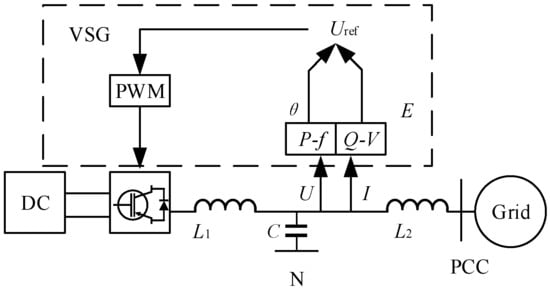
Figure 1.
Topology of inverter of conventional VSG.
The instantaneous active and reactive power measurements are designated as P and Q, respectively, ultimately generating the reference voltage amplitude E and phase angle θ. These signals further generate modulation signals. The synthesized modulation signals are ultimately converted into gate drive commands via PWM techniques, governing the inverter’s power switching states to generate the VSG’s target output voltage waveform [13,14,15].
2.1. Control System Structure
The active frequency regulation of a virtual synchronous machine is actually the simulation of a synchronous machine speed control system. The system exhibits both inertial and damping characteristics owing to the effects of rotational inertia J and damping coefficient Dp. The electromechanical dynamics of synchronous generator rotors are characterized by the swing equation:
The equation parameters are defined as follows: Tm denotes the mechanical input torque, Te represents the electromagnetic counter-torque, Td indicates the damping torque component, ωn is the nominal angular velocity (rated speed), ω stands for the instantaneous rotor angular velocity, and Dp signifies the damping coefficient. Figure 2 presents the complete active power–frequency (P-f) control loop architecture.
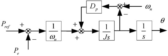
Figure 2.
Block diagram of active-frequency control.
2.2. Reactive-Voltage Controller
In VSG, the role of the reactive power–voltage controller is to dynamically regulate the reactive power output to maintain the grid voltage stability, as specifically indicated by the following equation:
In Equation (2), E0 denotes the grid’s effective voltage, Uref signifies the system’s output reference voltage, and U represents the system’s input voltage. Dq is the reactive damping coefficient; Qref refers to the reactive reference value; and Q is the reactive power output by the system. Under stable grid voltage conditions, the voltage regulation circuit output converges to zero, yielding the reactive power–voltage control block diagram illustrated in Figure 3.
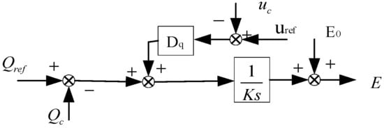
Figure 3.
Block diagram of power–voltage control reactive.
The reference voltage u* abc at the inverter side in the ABC coordinate system is formed by combining the phase angle θ of the VSG active frequency loop output with the reference voltage amplitude e of the reactive voltage loop output, as shown in Equation (3):
3. Dual-Module Virtual Synchronous Generator Control Architecture
3.1. Power Characteristic Analysis of VSG Under Voltage Unbalance Conditions
As illustrated in Figure 1, under three-phase voltage imbalance scenarios, the VSG output voltage and grid voltage exhibit distinct positive- and negative-sequence components through symmetrical component decomposition [16,17]. Following transformation into the α-β coordinate system, the VSG output voltage U is expressed by Equation (4):
The VSG output current I is given by Equation (5):
Equations (4) and (5) employ boldface vectors U and I to denote VSG output voltage and current, respectively, with superscripts VSG+/VSG− distinguishing positive-/negative-sequence components, while subscripts α/β identify their α-β reference frame projections. With the positive-sequence output voltage’s initial phase angle set to zero as a reference, with φ− representing the negative-sequence voltage phase angle, while φ+ and φ− correspond to the positive-sequence and negative-sequence current phase angles, respectively, the VSG output power can be calculated using Equation (6):
Equation (6) reveals that the VSG output active power (p) and reactive power (q) consist of two primary components: (1) the constant terms represented by P0 and Q0, and (2) the oscillatory components at 2ω frequency denoted by Pc2, Ps2, Qc2, and Qs2. Their interrelationships are mathematically expressed in Equations (7) through (9).
Assuming that the constant power components P0 and Q0 are the superposition of positive and negative order components, Equation (7) can be decomposed into Equations (10) and (11):
Based on Equations (10) and (11), to maintain symmetrical output currents from the VSG or achieve complete suppression of negative-sequence currents, it is essential to regulate the negative-sequence power components P0− and Q0− to zero, which represents a critical enhancement in VSG control strategy.
3.2. Conventional at Unbalanced Voltage VSG
It can be seen from Figure 2 and Figure 3 that under steady state, the VSG can be represented as an equivalent AC voltage source model, as illustrated in Figure 4a. This voltage source exclusively generates positive-sequence voltage components and inherently lacks the capability to produce negative-sequence voltages [18,19]. Correspondingly, Figure 4a may be further divided into two different circuits, as shown in Figure 4b,c.
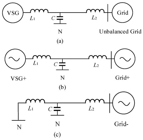
Figure 4.
Sequence component decomposition analysis of VSG under grid voltage imbalance conditions: (a) VSG-unbalanced grid system; (b) positive sequence part; (c) negative sequence part.
In Figure 4b, if the grid is balanced and symmetric, P0+ and Q0+ are the active and reactive power feedbacks of the VSG, respectively. When the system is unbalanced, the power feedback of VSG changes from P0+ and Q0+, as shown in Equation (8). The introduction of negative-sequence components Q0− and P0− induces steady-state errors in both active and reactive power control loops of the VSG+ module. These power regulation errors ultimately manifest as deviations in the VSG+’s output reactive power, specifically affecting the magnitude of its positive-sequence output voltage.
In Figure 4c, since the VSG does not have negative-sequence voltage output capability, the system is equivalent to a negative-sequence grid directly grounded through a small impedance, which leads to large negative-sequence currents.
Under grid imbalance conditions, the VSG output current represents a superposition of positive-sequence and negative-sequence components, as illustrated in Figure 4b,c. Due to the uncontrolled nature of negative-sequence current and low line impedance characteristics, even minor voltage unbalance can generate significant negative-sequence current components.
This results in substantial phase-sequence and amplitude imbalance in the three-phase current, which adversely affects grid stability and compromises VSG control system performance. Consequently, advanced control measures must be implemented to mitigate imbalance effects.
3.3. Dual-Module VSG Control Architecture for Unbalanced Grid Conditions
In view of the shortcomings of the virtual synchronous machine in the asymmetric situation in the previous section, it is improved, and an improvement scheme based on the virtual synchronous machine is given. Figure 5a presents the detailed control architecture. The acquired voltage and current signals undergo symmetrical component decomposition via sampling, this process generates separate positive- and negative-sequence components, enabling independent calculation of both positive-sequence (P+/Q+) and negative-sequence (P−/Q−) power outputs from the VSG through Equations (10) and (11). After the decoupled positive and negative sequence power is calculated, the two VSG modules (VSG+ and VSG−) are used to control the positive and negative sequence power, respectively. The VSG+ module receives P0+ and Q0+ as feedback and outputs u1+. The VSG− module connects P0− and Q0− as feedback and outputs modulation wave u1−. See Figure 5b,c for details.
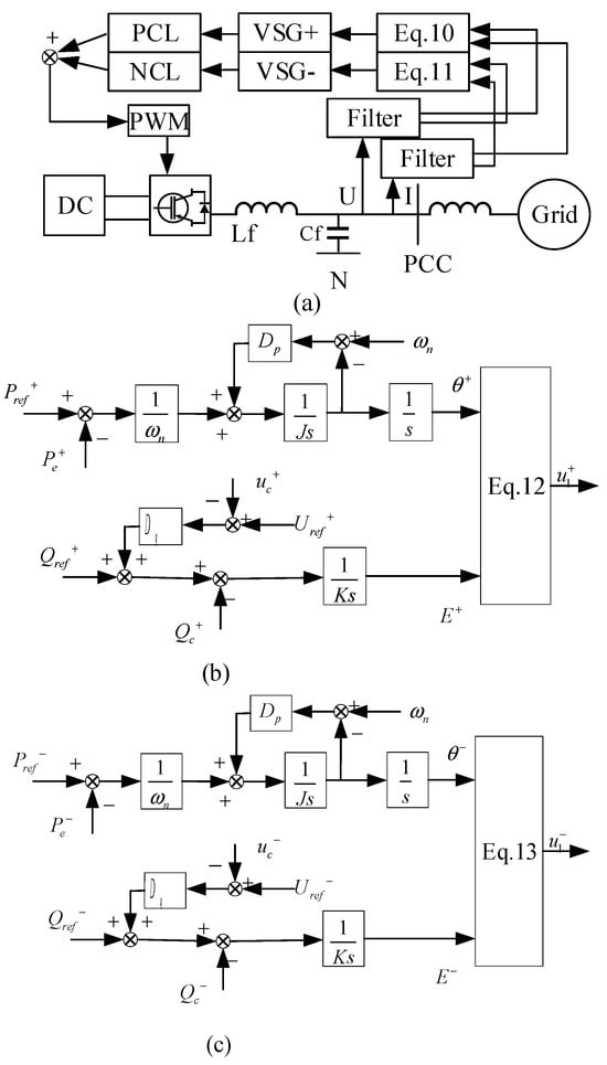
Figure 5.
Dual-mode VSG control diagram: (a) dual-module VSG control schematic; (b) VSG+ details; (c) VSG− details.
3.4. Dual-Loop Voltage and Current Control Architecture
The dual-loop current control serves as a fundamental component in grid-tied microgrid systems, functioning to maintain voltage/current stability while providing overvoltage/overcurrent protection. Conventional PI controllers are typically implemented for both current and voltage regulation [20].
The reference input for the voltage outer loop is obtained from the VSG output. Within the d-q reference frame, the voltage outer loop’s reference signal is mathematically expressed as follows:
where u1d and u1q, respectively, represent the voltage component of the droop controller output on the d and q axes, the terms ud+ and uq+ represent the positive-sequence d-axis and q-axis voltage components of the grid, while id+ and iq+ denote the reference values for the corresponding positive-sequence current components (denoted as id+ * and iq+ *, respectively) represent the grid-side current’s positive-sequence quantities in the d-q reference frame. Applying Laplace transformation yields the positive-sequence current relationship in the complex frequency domain, expressed as follows:
By applying steady-state assumptions to the voltage and current components, the aforementioned current relationship can be simplified to yield the time-domain representation of the positive-sequence current as follows:
The negative-sequence current components can be derived through an analogous methodology.
In order to achieve the control objective of balancing the current and to simplify the signal calculation, as well as to ensure that no mode switching is required in case of faults, the current is selected as the control variable. The control scheme employs a quasi-proportional-resonant (quasi-PR) controller to generate voltage reference signals, augmented by virtual impedance compensation. The controller’s transfer function is given by the following:
where kp, kr, and ωc are the proportionality coefficient, resonance coefficient, and cutoff bandwidth of the controller. The controller is able to balance the current efficiently and provide stable control in different operating modes of the respective quasi-PR.
The virtual impedance can simulate the behavior of the actual impedance and enhance the system’s resistance to grid voltage fluctuations. In the case of grid voltage imbalance, the virtual impedance helps to stabilize the current output and prevent the system from excessive current fluctuations, thus enhancing the stability of the grid-connected system. It effectively isolates the unstable factors and interference signals in the power grid and improves the anti-interference capability of the grid-connected system. In Figure 6, QPR represents a quasi-PR controller.

Figure 6.
Voltage−current dual−loop control structure.
The integrated control strategy enables precise regulation of virtual impedance and quasi-PR compensation for both positive- and negative-sequence power outputs in the VSG. This approach enhances power regulation capability, optimizes current loop dynamics, and improves the control accuracy with faster transient response.
When balanced current control is achieved, the grid-connected current becomes purely sinusoidal without negative-sequence components, allowing the negative-sequence current reference to be set to zero. However, since the grid voltage still contains negative-sequence components, both active and reactive power outputs from the VSG exhibit 2ω frequency oscillations. To maintain current balance while suppressing negative-sequence currents, the quasi-PR controller processes the error between the current reference and measured grid current to generate voltage reference signals, thereby effectively eliminating negative-sequence currents and ensuring balanced operation.
In the d-q reference frame, the voltage and current dual-loop control generate distinct positive- and negative-sequence output components, denoted as ud+*, uq+* for positive-sequence and ud−*, and uq−* for negative-sequence quantities, respectively. Therefore, a micro-network-based voltage–current double loop control scheme is proposed, as shown in Figure 6, and it is simulated.
4. System Operation and Performance Analysis
4.1. Operating Environment and Conditions
To verify the effectiveness of the dual-module control strategy, the used VSG MATLAB/Simulink environment is for simulation tests (https://ww2.mathworks.cn/). The constructed power system model includes the power module, inverter, control loop, and grid model, and the rated power is the VSG 20 kW, a 10% drop, by comparing the traditional in the grid at sec, a phase voltage of 0.7 occurs. The performance of the strategy in terms of dynamic response, power tracking accuracy, and system stability is analyzed using a dual-module VSG control strategy with the incorporation of the VSG PI control.
4.2. Active Power
Under different control methods, Figure 7 presents the active power (P) operational characteristics of the microgrid system.
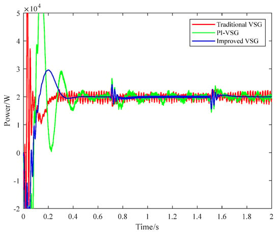
Figure 7.
Active power output under different methods.
It can be seen that the three-phase voltage is balanced at the initial stage, but the control effect of traditional VSG control (red curve) is not ideal, and there are problems such as large fluctuation amplitude of overshoot. The fluctuation amplitude decreases after PI regulation (green curve) is added, but there is a certain overshoot, and the active power fluctuation still exists after the voltage returns to balance. In contrast, the overshoot of the proposed control strategy (blue curve) is significantly reduced and the regulation time is reduced. During grid imbalance conditions, this method effectively mitigates active power oscillations and enhances grid power quality, demonstrating significant advantages in three key aspects: (1) accelerated dynamic response, (2) reduced steady-state tracking error, and (3) elimination of abnormal power fluctuations.
4.3. Reactive Power
Figure 8 compares the reactive power output of the three control strategies.
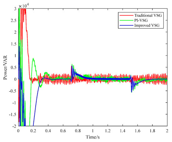
Figure 8.
Reactive power output under different methods.
Traditional VSG control (red curve) has obvious overshoot and irregular fluctuation. Although the PI control (green curve) is improved, the fluctuation is suppressed in the equilibrium state, but the fluctuation still exists in the unbalanced condition. And there is a certain overshoot. The proposed dual module VSG control (blue curve) has good surge suppression capability and reduced regulation time. Under the unbalanced condition, the power fluctuation is the minimum and can quickly reach the steady state. When encountering a system change, the control method can make the system stable again after a short adjustment. The experiment shows that the method is obviously superior to other methods in inhibiting reactive power fluctuation. The anti-interference of the proposed method is fully proven.
4.4. Current Balance Stability
Figure 9 shows the current output for the three control methods. When only the VSG control is used (as shown in Figure 9a), the current distortion is obvious. The symmetry is damaged and cannot be restored to its original state. This condition significantly compromises grid power quality standards.
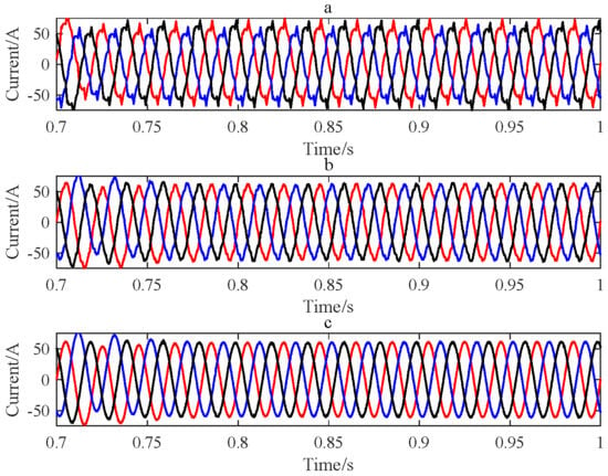
Figure 9.
Three-phase current output under different methods: (a) traditional VSG; (b) PI-VSG; (c) improved VSG.
With PI regulation (as shown in Figure 9b), the current distortion effect is improved. However, the regulation time is too long and the current contains more harmonics. Figure 9c shows the dual-module VSG control strategy with a QPR controller, which can quickly restore the system balance state when the grid voltage drops, so as to ensure the power quality. Experimental verification confirms the enhanced grid disturbance immunity of the developed control scheme during voltage imbalance scenarios, without compromising implementation feasibility.
4.5. THD Analysis
Total Harmonic Distortion (THD) is an important indicator of current quality, and a high THD value not only leads to an increase in system losses, but also may cause disturbances to the power grid and affect the normal operation of power equipment. Reducing THD is a key objective to improve the quality of grid operation. When the control only is used, its VSG THD is much larger than 5%. For the VSG control strategy, by adding limited control accuracy with the control, the PI THD is 4.18%. Although this value is lower than 5%, the output current still contains high harmonic components, resulting in poor grid current quality. The proposed research method effectively reduces the harmonic distortion, as shown in Figure 9, and the THD is reduced to 1.09%, as shown in Figure 10. This improvement reduces the harmonic pollution of the system, ensures the quality of the grid output current, and enhances the overall operational efficiency and stability of the power system. It reflects the advantages of the proposed method in reducing harmonic distortion and has important practical application value.
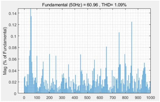
Figure 10.
THD analysis of the proposed control method.
5. Conclusions
Voltage imbalance in microgrids significantly degrades power quality, a condition where conventional VSG control fails to deliver satisfactory performance. The developed dual-module VSG architecture overcomes this limitation through integrated virtual impedance and quasi-PR control schemes, enabling precise decoupled regulation of both positive- and negative-sequence power components. This approach facilitates separate identification and coordinated management of both power components, leading to enhanced current regulation loop performance while improving overall system stability and dynamic response characteristics. The dual-module VSG control approach demonstrates particular efficacy in maintaining grid-connected system stability during voltage imbalance events, effectively mitigating detrimental effects caused by voltage fluctuations.
Simulation analysis demonstrates the proposed control strategy’s efficacy in enhancing system stability, reducing harmonic distortion, and improving current quality, and its effectiveness in practical application is verified. By optimizing the control strategy, the system can regulate the reactive power more accurately and reduce the harmonic component, so as to provide a solid guarantee for the stable operation of the power grid. The research has high practical value, which lays a solid foundation for the stable operation of smart grid and grid connection systems in the future and also provides a reference for further research in relevant fields.
Author Contributions
For this research article, the conceptualization was handled by L.F. and M.W. The methodology, software, formal analysis, investigation, and data curation were primarily carried out by L.F. The validation work was jointly conducted by L.F. and M.W. M.W. was responsible for the original draft preparation and visualization, while L.F. handled the writing—review and editing. L.F. also oversaw the project management and funding acquisition. All authors have read and agreed to the published version of the manuscript.
Funding
This research received no external funding.
Acknowledgments
This work was supported by the Intercollegiate Cooperation Project of Colleges and Universities in Liaoning Province (Grant [2020] 28) and the Key Project of Liaoning Provincial Department of Education (LJKZZ20220057).
Conflicts of Interest
The authors declare there are no conflicts of interest.
References
- Hannan, M.; Tan, Y.S.; Al-Shetwi, Q.A.; Jern, K.P.; Begum, R.A. Optimized controller for renewable energy sources integration into microgrid: Functions, constraints and suggestions. J. Clean. Prod. 2020, 256, 120419. [Google Scholar] [CrossRef]
- Ehsan, R.; Sirus, M.; Mahmoud, Z.; Zadehbagheri, M.; Kiani, M. Probabilistic reliability management of energy storage systems in connected/islanding microgrids with renewable energy. Electr. Power Syst. Res. 2023, 214 Pt A, 108891. [Google Scholar]
- Samuel, O.; Adeyemi, O.; Christiana, O. Potential of using floating solar photovoltaic and wind farms for sustainable energy generation in an existing hydropower station in Nigeria. Clean Technol. Environ. Policy 2023, 25, 1921–1934. [Google Scholar]
- Liu, S.; Hu, P.; Yu, Y.; Kiani, M. A novel fault ride through strategy for grid-connected virtual synchronous Generators: Power angle stability enhancement and current limiting. Int. J. Electr. Power Energy Syst. 2024, 162, 110293. [Google Scholar] [CrossRef]
- Askarov, A.; Ruban, N.; Bay, Y.; Ufa, R.; Malkova, Y.; Suvorov, A. A feedforward control for increasing the damping effect of enhanced current-controlled virtual synchronous generator. Electr. Power Syst. Res. 2024, 234, 110659. [Google Scholar] [CrossRef]
- Zhang, M.; Mu, L.; Chen, G.; Fang, C. A circulating current suppression strategy of VSG based on adaptive virtual complex impedance. Electr. Power Electr. Power Syst. Res. 2024, 228, 110065. [Google Scholar] [CrossRef]
- Cheng, Q.; Lai, Y.; Xie, Y.; Chen, Y.; Shen, Z. Bilateral Lyapunov control strategy for MMMC under three-phase voltage unbalance. J. Electr. Mach. Control 2023, 27, 96–107. [Google Scholar] [CrossRef]
- Wu, T.; Wang, A.; Xu, Y. A rapid harmonic detection method for grid-connected photovoltaic when three-phase voltage is unbalanced. J. Low Carbon Technol. 2021, 16, 822–830. [Google Scholar] [CrossRef]
- Kahia, B.; Bouafia, A.; Chaoui, A.; Zhang, Z.; Abdelrahem, M.; Kennel, R. A direct power control strategy for three level neutral-point-clamped rectifier under unbalanced grid voltage. J. Electr. Power Syst. Res. 2018, 161, 103–113. [Google Scholar] [CrossRef]
- Yang, X.; Li, H.; Jia, W.; Liu, Z.; Pan, Y.; Qian, F. Adaptive Virtual Synchronous Generator Based on Model Predictive Control with Improved Frequency Stability. Energies 2022, 15, 8385. [Google Scholar] [CrossRef]
- Suvorov, A.; Askarov, A.; Ruban, N.; Rudnik, V.; Radko, P.; Achitaev, A.; Suslov, K. An Adaptive Inertia and Damping Control Strategy Based on Enhanced Virtual Synchronous Generator Model. Mathematics 2023, 11, 3938. [Google Scholar] [CrossRef]
- Wang, J.; Ramli, N.; Aziz, N.H.A. Modeling and adaptive control strategy of hybrid microgrid based on virtual synchronous generator. Adv. Control. Appl. Eng. Ind. Syst. 2023, 6, e155. [Google Scholar] [CrossRef]
- Zhou, K.; Jin, Q.-X.; Mo, Z.-Y.; Lu, B.-H. Harmonic suppression and fault ride-through strategy for power grid under virtual synchronous machine grid-connected operation. Power Syst. Prot. Control 2024, 52, 166–173. [Google Scholar] [CrossRef]
- Yang, X.; Yang, Y.; Pan, Y.; Gu, W.; Yang, H.; Jia, W. A virtual synchronous generator control strategy based on RBF-LADRC. J. Sol. Energy 2024, 45, 319–325. [Google Scholar] [CrossRef]
- Wang, Z.; Chen, Y.; Li, X.; Luo, C.; Fu, Y.; Wang, H.; Fu, J. Difference-free coordinated control strategy of multiple virtual synchronous generator frequencies for islanded microgrids. Power Syst. Prot. Control 2024, 52, 12–23. [Google Scholar] [CrossRef]
- Liu, Z.; Tang, N.; Zhang, H.; Wang, T.; Lu, X. Virtual synchronous generator model predictive control under unbalanced grid voltage. Electrotechnology 2024, 1, 12–17. [Google Scholar] [CrossRef]
- Wang, Y.; Wang, H.; Zhuang, B.; Zhou, Z.; Lv, W. VSG-based control strategy for grid-connected inverter under grid voltage unbalance. Renew. Energy 2022, 40, 696–702. [Google Scholar] [CrossRef]
- Zheng, T.; Chen, L.; Guo, Y.; Mei, S. Comprehensive control strategy of virtual synchronous generator under unbalanced voltage conditions. IET Generation. Transm. Distrib. 2018, 12, 1621–1630. [Google Scholar] [CrossRef]
- Zeng, Z.; Shao, W.; Li, H.; Ran, L.; Qin, S. Virtual synchronous generator unbalanced voltage control in an islanded microgrid. Chin. J. Electr. Eng. 2017, 37, 372–381. [Google Scholar] [CrossRef]
- Cao, Z.Y.; Wang, N.H.; Chen, B. Unbalanced voltage control of virtual synchronous generator in isolated micro-grid. IOP Conf. Ser. Mater. Sci. Eng. 2017, 211, 012020. [Google Scholar] [CrossRef]
Disclaimer/Publisher’s Note: The statements, opinions and data contained in all publications are solely those of the individual author(s) and contributor(s) and not of MDPI and/or the editor(s). MDPI and/or the editor(s) disclaim responsibility for any injury to people or property resulting from any ideas, methods, instructions or products referred to in the content. |
© 2025 by the authors. Licensee MDPI, Basel, Switzerland. This article is an open access article distributed under the terms and conditions of the Creative Commons Attribution (CC BY) license (https://creativecommons.org/licenses/by/4.0/).