Article

Efficiency Testing of Pelton Turbines with Artificial Defects—Part 2: Needles and Seat Rings

Lucerne School of Engineering and Architecture, Lucerne University of Applied Sciences and Arts, 6048 Horw, Switzerland
*
Author to whom correspondence should be addressed.
Energies 2025, 18(11), 2725; https://doi.org/10.3390/en18112725
Submission received: 6 March 2025 / Revised: 12 May 2025 / Accepted: 19 May 2025 / Published: 23 May 2025

Abstract

The erosion of Pelton turbine components in mountainous areas with high sediment input is a major challenge for energy- and cost-efficient operation. Quantitative data on possible efficiency losses associated with local damage are needed. A systematic experimental study was carried out on a model turbine to determine the efficiency losses caused by damaged needles and seat rings. For this purpose, artificial patterns of erosion-like damage were generated on the surfaces of needles and seat rings. These patterns were gradually deepened, and hill charts were measured repeatedly. The combination of needle and seat ring defects was also studied, and the finding is that superimposing the individual efficiency losses of the needle and seat ring resulted in the same efficiency loss measured for both damaged parts. The results of the measurement campaign show that damaged needles should be replaced at an early stage of deterioration, as efficiency losses can quickly add up to several percent and become unacceptable at partial load operations of the turbines.

1. Introduction

The wear of turbine parts caused by abrasive particles in sediment-laden flows is a major challenge for the operation and planning of maintenance measures for hydro machinery. Summaries of the processes involved in hydro-abrasive erosion, a discussion of parts of Pelton turbines exposed to hydro-abrasive erosion, and typical damage descriptions are provided in previous review articles [1,2].
Damage to Pelton injector nozzles and the effect this has on efficiency is the focus of this contribution. Nozzles are the parts of Pelton turbines that are exposed to the highest velocities, as their purpose is to convert all the available energy in the flow into kinetic energy. As stated in the standard [3], erosion progresses with increasing flow velocity to the third or even higher power, making nozzles prone to high erosion rates. Uncoated injector needles and seat rings are particularly susceptible to erosion. It is also observed that they are further damaged by the onset of cavitation after the initial sediment erosion. In addition to the high velocities inside the injectors, the curvature of the particle-charged streamlines also has a predominant influence [4,5,6,7]. Unfortunately, high-efficiency injectors with low energy losses and uniform velocity distributions at the outlet have a more curved flow path by design and are subject to higher erosion rates.
The efficiency of the turbines is affected by two effects. On the one hand, damage to the needles and seat rings causes local dissipation, which influences local pressure distributions and reduces the hydraulic energy of the jet. On the other hand, the distortion of the jet with a non-uniform velocity distribution, surface deformation, and dispersion affects the process of the conversion of hydraulic into mechanical energy within the turbine runner, which is far more important than the local dissipation [8].
A series of cases of damaged needles and seat rings are reported in the literature [9,10,11,12,13,14]. The work of Bajracharya et al. [11] presents detailed measurements of an eroded injector and the distribution of the erosion rate on the surface of the needle in the Chilime hydropower plant, Nepal. Cateni et al. [12] point out the influence of nozzle damage on jet quality and its influence on efficiency. Morales et al. [13] measured, in the Chivor power plant, Columbia, the eroded surface patterns and tried to reproduce the same hydro-abrasive phenomena in a controlled laboratory environment. Din et al. [14] performed detailed optical scan measurements of damaged needles and seat rings in the hydropower plant of Chenani, India.
The observed patterns on the needles often show unevenly distributed erosion marks on the circumference of the needles, as exemplified in [11]. The authors explain this occurrence with a secondary flow that is generated in manifolds and elbows that are upstream of the injector nozzles. Damage found in seat rings is generally more evenly distributed around the circumference [14].
Numerical studies on erosion in injectors, needles, and seat rings have been successfully performed in recent years [10,11,12,13,15]. A new approach with respect to CFD is to model defects on needles and to study the effects of such damage on pressure distributions and jet deformation, as is presented in [16,17]. From previous research [18], it is known that jet quality has a major influence on the efficiency of Pelton turbines. Such simulations are a start in relation to predicting the effects of first artificial and then scanned defects on the efficiency of the energy conversion process in the turbine.
For this study, the interest lies not in the change in erosion damage or efficiency over time, but in the actual efficiency of the turbines due to the current damage of the injector parts. For this reason, artificial defects such as those typically observed in hydro-abrasive erosion have been applied. By performing tests with different defects, both individually and in combination, it becomes possible to distinguish between the effects of the different types of defects on efficiency and helps to better understand the loss mechanisms.
The experimental results of efficiency measurements on a model Pelton turbine and an injector with artificially machined defects on nozzles and seat rings are presented in this manuscript.
The test rig, the experimental procedure, and a detailed uncertainty analysis are presented in [19]. To study the effects of damaged injectors, a series of interchangeable needles and seat rings were fabricated. After a study of the typical erosion patterns on the injectors of Pelton turbines in various hydropower plants, it was decided to model the applied damages with uniform grooves. The size, depth, and distribution of these grooves were chosen based on various exponents exhibited in hydropower plants. The idea behind these abstracted shapes was not only to approximate real erosion patterns and have a feasible, not-too-complicated machining process, but also to have a geometry which might be used in further studies with CFD.
The depth and length of the grooves were gradually increased in the study. The effect of the alignment in the circumferential direction of the local damage was also systematically investigated. For each modification, a complete hill chart was recorded based on 99 measurement points with varying speed and discharge. Based on the measured hill chart of the undamaged injector, it was possible to determine the drop in efficiency over the entire hill chart for each machining step.
The data generated in this study show a relationship between the actual erosion of the injector parts and its impact on the efficiency of the entire Pelton turbine. This knowledge can then be used for planning a renewal. The decision as to when and to what extent a turbine runner or injector needs to be refurbished or replaced can only be made on the basis of good basic data such as the current efficiency of the turbine, the usual range of operation, the current electricity price, or the refurbishment costs [20,21].
For future research, the experimental data presented here will also serve as a basis for the validation of CFD simulation techniques, as the geometric defects are geometrically well defined and the operating and efficiency data were determined very accurately.

2. Processing Steps of Needles and Seat Rings

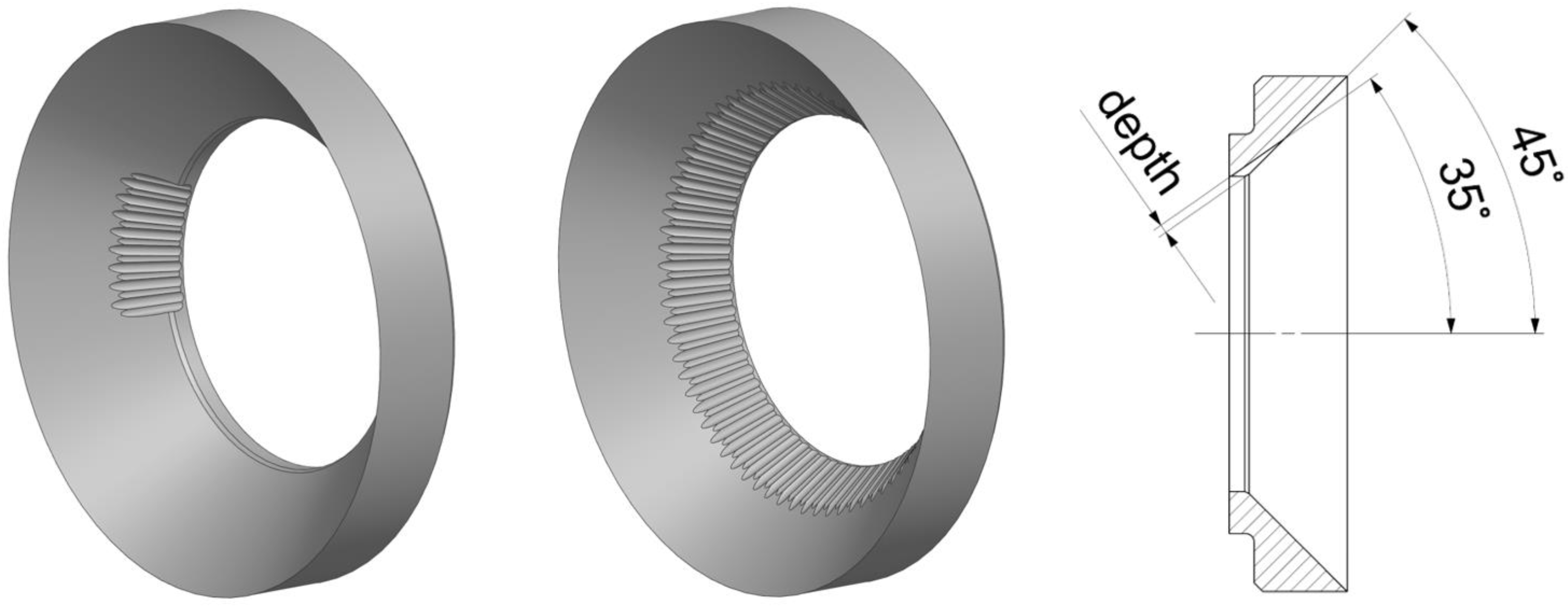
In particular, scans of eroded needles and seat rings, as well as data published by Din [14], Bajracharya [11], and examples found in some other plants, were helpful in determining the geometry of artificial erosion patterns. Finally, it was decided to machine grooves that were equal in size onto the surfaces of the seat rings and the needles, see Figure 1 and Figure 2. The maximum groove depth kt was increased in three steps from 0.25 mm to 0.75 mm. Making the depth dimensionless with the pitch circle diameter D0 of 36.6 mm, this results in steps of 0.00683. For the first processing step, the grooves had a width kb of 0.86 mm; for all subsequent steps, the width was set to 1 mm. The inner contour was rounded with a radius kr of 0.5 mm. The length of the grooves was adapted to the available space in the individual steps (Figure 3).

3. Hill Chart Measurements

3.1. Test Rig and Procedure

The test rig, described in [19], consists of a feed pump that supplies a single-nozzle horizontal Pelton turbine. The injector is equipped with an internal servomotor; the angles of the nozzle and needle are 90° and 50°. The nozzle diameter D0 is 36.6 mm, while the inner bucket width B is 80 mm. The electromagnetic flow meter is calibrated before and after the test series using the flying start-and-finish method, according to [22].
The shaft torque was measured according to the principle of the balancing arrangement, as described in [23]. The torque acting on the rotor is measured at the torque arms of the swinging frame of the generator and the bearing pedestal. The second permits the frictional torque in the runner bearings to be determined.
The uncertainty of the hydraulic efficiency, presented in [19], was calculated to be in the range of 0.17–0.4% depending on the operating point. However, more importantly for these tests with stepwise increased defects is the repeatability, which was shown to be within a band of ±0.15% in the entire range.
Three needles (N 0, N 1, and N 2) and three seat rings (M 0, M 1, and M 2) were used in the series of tests presented here. The base variants N 0 and M 0 were left unmachined as a reference for all tests. The others were processed in steps (S), as shown in Table 1.
The grooves in the 0° angle position are aligned with the splitter on the side of the bucket root. The grooves in the 90° angle position are lateral and distort the flow in the bucket base.
For each machining step and any combination of nozzles and seat rings, the complete hill chart was measured, resulting in a total of 32 hill charts. During a hill chart measurement, the head H was kept constant at 120 m. The flow rate was varied by operating the nozzles. The rotational speed of the generator was then changed for each constant volume flow. For each hill chart, 99 points were measured. The following non-dimensional quantities, as defined in [23], were used for the hill charts:
Speed   factor :   n E D = n   D   E 0.5
Discharge   factor :   Q E B = Q B 2 E 0.5
E [m2/s2]—specific hydraulic energy (Equation (3));
n [1/s]—runner speed;
Q [m3/s]—flow rate;
D [m]—0.3277 m—pitch circle diameter;
B [m]—0.08 m—bucket width.
Simplifying the equation for a horizontal-axis, single-jet Pelton turbine with the pressure transducer for measuring the relative pressure p1 mounted at the level of z1 according to [23], Section 8.2.3.2.2, as well as the velocity v1 at the inlet, gives the following:
Specific   hydraulic   energy :   E = p 1 ρ - + v 1 2 2
The turbine efficiency was evaluated in accordance with the definition provided in [23].

3.2. Procedures for Measurement and Evaluation

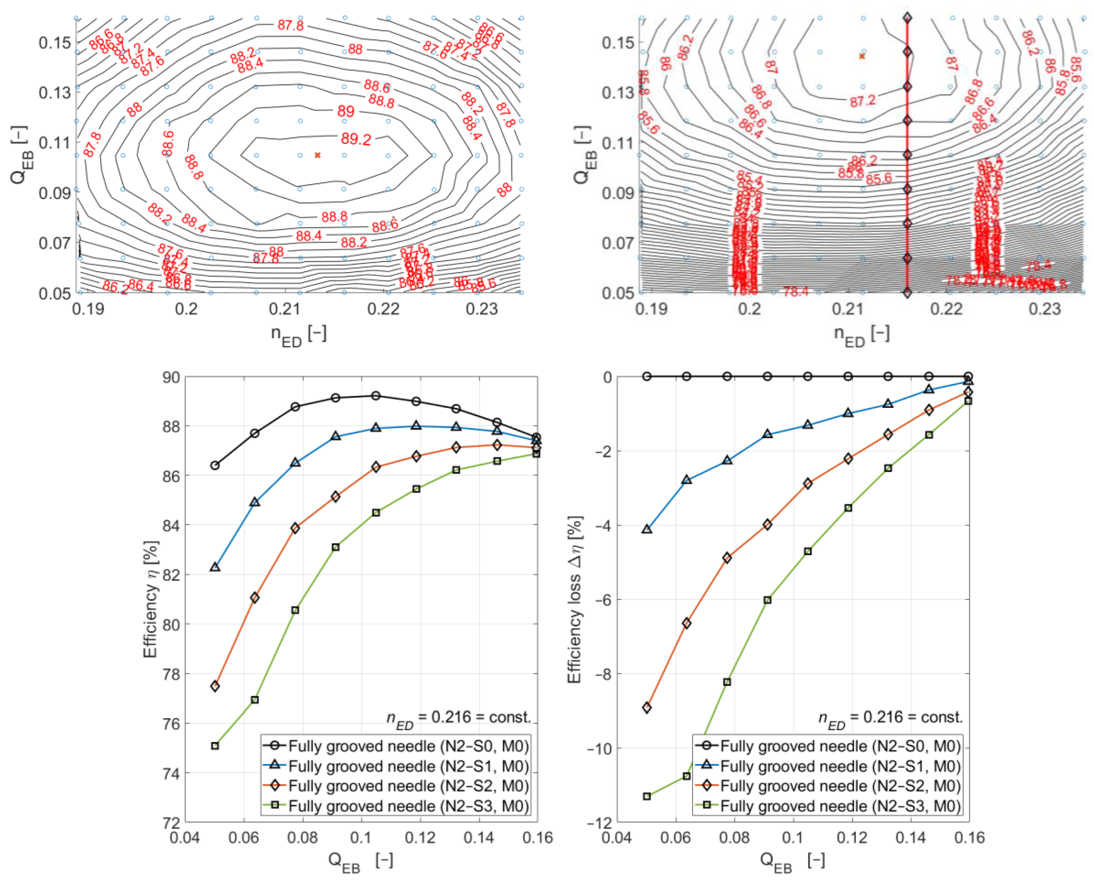
As an example of the evaluation procedure, the measurements of the fully grooved needle case are presented below. The full hill chart, interpolated from the 99 measured operating points, is displayed in the top left of Figure 4. The maximum efficiency lies slightly above 89%. After two machining steps—shown in the top right of Figure 4—the drop in efficiency is already considerable, around 3% at the position of the original best point. The new best point is shifted towards larger flow rates, and the maximum efficiency in this point is 2% below the original maximum efficiency.
As representative curves showing the efficiency and efficiency drop, the data at nED = 0.216 are plotted at the bottom of Figure 4. Obviously, the damaged needle affects efficiency to a much larger degree at the low flow rates. Originally, four machining steps were planned, but since the efficiency drop was unexpectedly high, it was decided to stop at step 3.

3.3. Results of the Partially Grooved Needle and Seat Ring

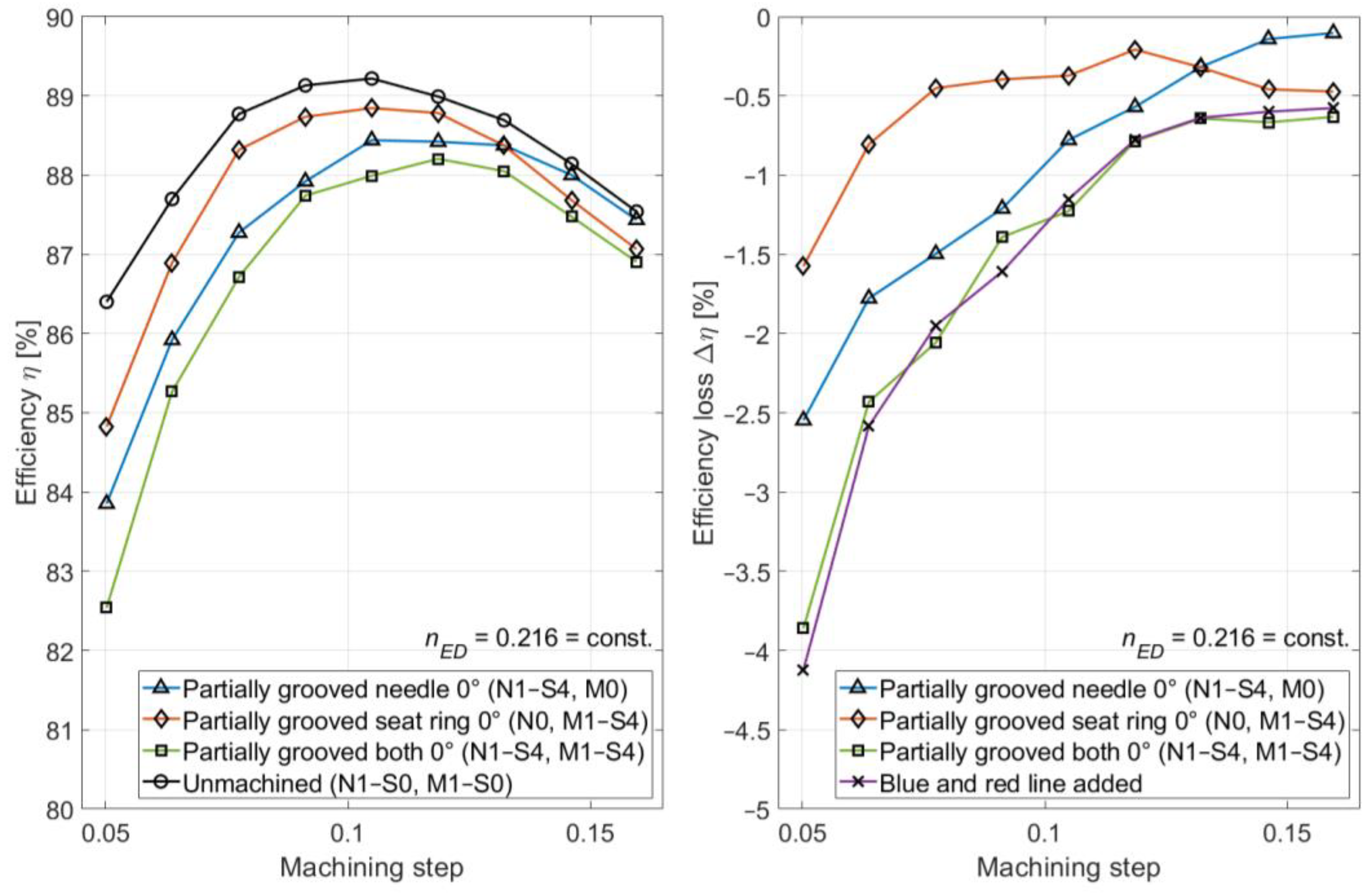
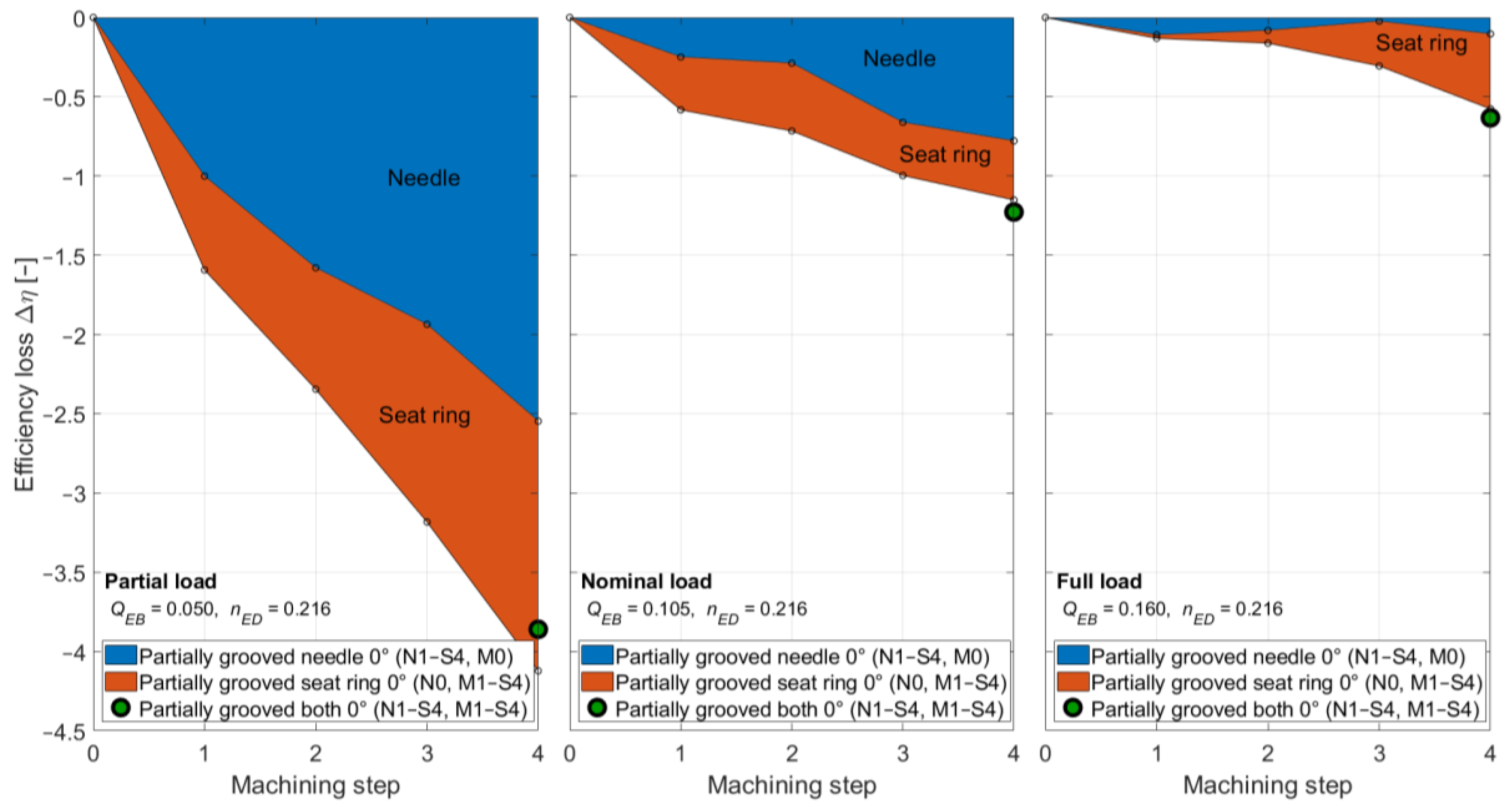
Following the explanation of the process and the presentation of the results for the fully grooved needle in the previous section, only the results for the partially machined parts are presented below. Figure 5 and Figure 6 show the results for the partially grooved needle and seat ring in two different angular positions. Figure 5 shows the efficiency and efficiency drop for the partially grooved needle, the partially grooved seat ring, the combination of both after 4 machining steps, and the original, unmachined case. The grooves of the needle and seat ring were positioned at the same angle of 0°, so that they aligned with the splitter on the side of the bucket root. The scaling of the graphs differs from those in Figure 4 because the effect of the partial grooves is significantly less than that of the fully grooved needle. The best point is also less shifted towards the large flow rates. The interaction between the two defect types on the needle and seat ring is very small. The proof of this is that the superposition of the individual efficiency drops of the needle and seat ring (blue and red line, respectively) leads to the same result in a very good approximation as the measurement of the combined defects.
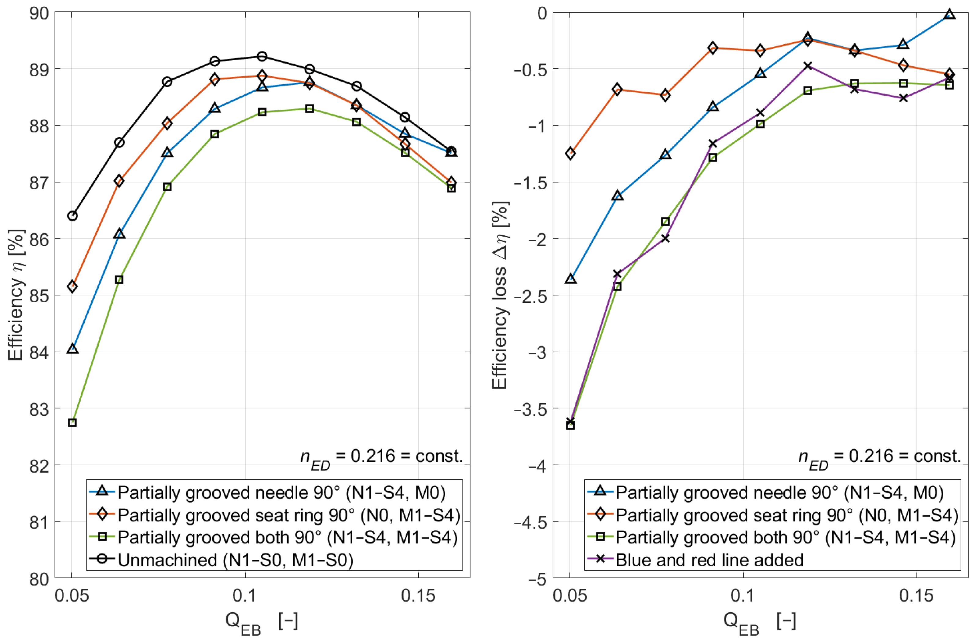
At an orientation of 90° of the partially grooved needles and seat rings, as shown in Figure 6, the observations are effectively the same as those found at 0°. The efficiency drops are slightly smaller. Again, the superposition of the individual efficiency drops of the needle and seat ring (blue and red line, respectively) leads, in very good approximation, to the same result as the measurement of the combined defects.

3.4. Results of the Fully Grooved Needle and Seat Ring

Figure 7 shows the case of the combination of the fully grooved needle (step 3) and fully grooved seat ring (step 4). The drop in efficiency is dominated by the effects of the needle. The efficiency losses due to the seat ring are an order of magnitude smaller than those due to the needle.
Superimposing the individual cases of the needle and seat ring (blue and red lines, respectively) underestimates the efficiency drop measured for the combination of the two. It would probably make more sense to check the superposition principle for a case in which the efficiency drops of the seat ring and needle are equally large.
No explanation has been found as to why the fully grooved seat ring does not lead to much higher efficiency losses than the partially grooved seat ring. The first step of the seat ring machining caused a major drop in efficiency, while the subsequent steps had only a minor influence. The machining selected for the fully grooved seat ring may not have been optimally chosen.

3.5. Combination of the Partially Machined Needle and Seat Ring

The series of measurements in Section 3.3 and Section 3.4 show the individual efficiency losses due to needle and seat ring machining. These measurements are shown in Figure 8 as superimposed blue and red areas. In order to verify that such a superposition of efficiency losses is permissible, a combined measurement was made with the damaged needle and seat ring in the last stage of machining. The results of these measurements are shown as green dots. The agreements for partial, nominal, and full load confirm that such a superposition of efficiency losses of individual damages is possible.

4. Conclusions

The uncoated needles and seat rings of injectors of Pelton turbines exposed to sediment-laden flows often show groove-like patterns of erosion damage. The data presented here enable a qualitative estimate of the efficiency losses depending on the depth and extent of the damage observed at injectors in hydropower plants. For a more quantitative prediction, the dimensionless and averaged depth of the grooves has to be measured on site.
In the laboratory measurements of the hill charts, the most serious efficiency drops were encountered with the fully grooved needle in partial load operation. Here, efficiencies decayed in the order of 10%, while at full load efficiency, dropped only by 1%, even after three steps of machining artificial grooves. In contrast to the grooves on the needle, the grooves on the seat ring had a much smaller influence, and even after four machining steps and at partial load, the efficiency loss was no more than 1%. A special feature of the grooves on the seat ring was that after the first step, the further reduction in efficiency was minimal; in addition, the fully grooved seat ring did not cause higher efficiency losses than the partially grooved seat ring.
The orientation of the grooves on the seat ring and the needles had only a minor influence on efficiency. The combination of needle and seat ring defects was also studied, and the most important finding is that superimposing the individual efficiency losses of the needle and seat ring resulted in the same efficiency loss measured for the combination of both damaged parts.
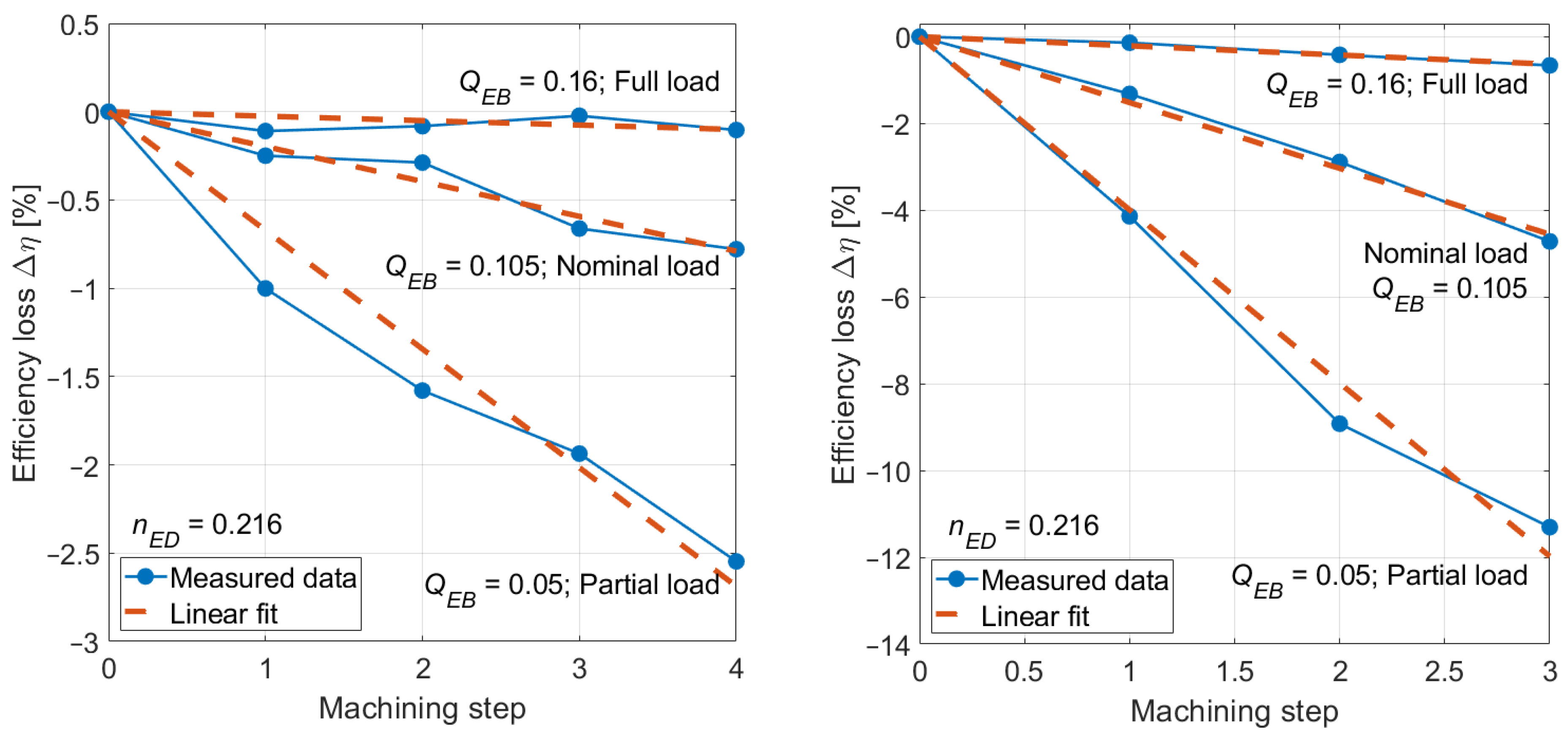
Another important finding of the measurements is that the efficiency losses of the turbine increase approximately linearly with increasing damage. The decay in efficiency for the partially and fully grooved needle for partial, nominal, and full load operation is shown in Figure 9. For the seat ring, the behavior is similar; however, the scatter is higher due to the lower values. It is probable that the specifications of the artificial erosion patterns and the machining steps for the seat ring were not chosen optimally at the beginning of the project. Further research in this area should consider different types of defects on the seat ring.
The knowledge of the presented results allows the plant operator to better plan the repairs or replacement of needles and seat rings. In general, it is recommended to use coated seat rings and needles in the presence of hydro-abrasive erosion, as these will resist erosion for a much longer period of time. If coated needles or seat rings are damaged, they should be replaced as soon as possible, as the softer ground material will erode quickly and result in significant losses.

Author Contributions

Measurements, investigation, and visualization: F.F.; conceptualization and writing—original draft: T.S.; funding acquisition, supervision, and project administration: E.C. All authors have read and agreed to the published version of the manuscript.

Funding

This research was funded by the Swiss Federal Office of Energy (SFOE [SI/502195]) and Axpo Power AG, Baden, Switzerland.

Data Availability Statement

The original contributions presented in this study are included in the article. Further inquiries can be directed to the corresponding author.

Conflicts of Interest

The authors declare no conflict of interest.

References

  1. Ge, X.; Sun, J.; Chu, D.; Liu, J.; Zhou, Y.; Zhang, L.; Chen, H.; Binama, M.; Zheng, Y. Sediment erosion on Pelton turbines: A review. Chin. J. Mech. Eng. 2023, 36, 64. [Google Scholar] [CrossRef]
  2. Shrivastava, N.; Rai, A.K. Hydro-abrasive erosion in Pelton turbines: Comprehensive review and future outlook. Renew. Sustain. Energy Rev. 2025, 207, 114957, ISSN 1364-0321. [Google Scholar] [CrossRef]
  3. IEC 62364:2019; Hydraulic Machines—Guidelines for Dealing with Hydro-Abrasive Erosion in Kaplan, Francis, and Pelton Turbines. International Electrotechnical Commission: Geneva, Switzerland, 2019.
  4. Guo, B.; Rai, A.K.; Zhang, J.; Liang, Q. Sediment-laden flow and erosion modeling in a Pelton turbine injector. Renew. Energy 2020, 163, 30–42. [Google Scholar] [CrossRef]
  5. Tarodiya, R.; Khullar, S.; Levya, A. Particulate flow and erosion modeling of a Pelton turbine injector using CFD-DEM simulations. Powder Technol. 2022, 399, 117168. [Google Scholar] [CrossRef]
  6. Shrivastava, N.; Rai, A.K. Parametric Investigation of Pelton Turbine Injector under Hydro-abrasive Erosion Conditions. J. Appl. Fluid Mech. 2024, 17, 89–104. [Google Scholar]
  7. Shrivastava, N.; Rai, A.K.; Abbas, A.; Xiao, X. Analysis of hydro-abrasive erosion in a high-head Pelton turbine injector using a Eulerian-Lagrangian approach. Proc. IMechE Part A J. Power Energy 2024, 238, 495–514. [Google Scholar] [CrossRef]
  8. Villacorta Benitez, R. Theoretische und experimentelle Untersuchungen an Einlaufdüsen von Freistrahlturbinen. Ph.D. Thesis, Swiss Federal Institute of Technology (Eidgenössische Technische Hochschule), Zurich, Switzerland, 1972. No. 4678. [Google Scholar]
  9. Brekke, H.; Wu, Y.L.; Cai, B.Y. Design of Hydraulic Machinery Working in Sand Laden Water. In Abrasive Erosion & Corrosion of Hydraulic Machinery; Duan, C.G., Karelin, V.Y., Eds.; Imperial College Press: London, UK, 2002; pp. 155–233. [Google Scholar]
  10. Thapa, B. Sand Erosion in Hydraulic Machinery. Ph.D. Thesis, Faculty of Engineering & Technology, Norwegian University of Science and Technology, Trondheim, Norway, 2004. [Google Scholar]
  11. Bajracharya, T.R.; Acharya, B.; Joshi, C.B.; Saini, R.P.; Dahlhaug, O.G. Sand erosion of Pelton turbine nozzles and buckets: A case study of Chilime Hydropower Plant. Wear 2008, 264, 177–184. [Google Scholar] [CrossRef]
  12. Cateni, A.; Magri, L.; Grego, G. Optimization of Hydro Power Plants Performance—Importance of rehabilitation and maintenance in particular for the runner profiles. In Proceedings of the 7th International Conference on Hydraulic Efficiency Measurements (IGHEM), Milan, Italy, 3–6 September 2008. [Google Scholar]
  13. Morales, A.M.; Pachon, I.F.; Loboguerrero, J.; Medina, J.A.; Escobar, J.A. Development of a test rig to evaluate abrasive wear on Pelton turbine nozzles. A case study of Chivor Hydropower. Wear 2017, 372–373, 208–215. [Google Scholar] [CrossRef]
  14. Din, M.Z.U.; Harmain, G.A. Assessment of erosive wear of Pelton turbine injector: Nozzle and spear combination–A study of Chenani hydro-power plant. Eng. Fail. Anal. 2020, 116, 104695. [Google Scholar] [CrossRef]
  15. Messa, G.V.; Mandelli, S.; Malavasi, S. Hydro-abrasive erosion in Pelton turbine injectors: A numerical study. Renew. Energy 2019, 130, 474–488. [Google Scholar] [CrossRef]
  16. Satyal, S.; Abregu, J.; Singh, B.; Nascimben, F.; Chitrakar, S.; Neopane, H.P.; Dahlhaug, O.G. Numerical Investigation of Effects of Ripple Type Needle Erosion on Pressure Inside a Pelton Nozzle. IOP Conf. Ser. Earth Environ. Sci. 2024, 1385, 012004. [Google Scholar] [CrossRef]
  17. Bhattarai, B.S.; Khatiwada1, A.; Vaidhya1, N.; Satyal, S.; Chitrakar, S. Numerical investigation of flow around the injector of a Pelton turbine due to eroded needle. IOP Conf. Ser. Earth Environ. Sci. 2024, 1385, 012003. [Google Scholar] [CrossRef]
  18. Staubli, T.; Abgottspon, A.; Weibel, P.; Bissel, C.; Leduc, J.; Leboeuf, F. Jet quality and Pelton efficiency. In Proceedings of the Hydropower & Dams International, Hydro 2009, Lyon, France, 26–28 October 2009. [Google Scholar]
  19. Fahrni, F.; Staubli, T.; Casartelli, E. Efficiency Testing of Pelton Turbines with Artificial Defects—Part 1: Buckets. Energies 2025. [Google Scholar]
  20. Abgottspon, A.; Staubli, T.; Bieri, E.; Felix, D. Economic optimization of maintenance measures based on continuous efficiency monitoring. In Proceedings of the 21st International Seminar on Hydropower Plants (Viennahydro 2022), Vienna, Austria, 9–11 November 2022. [Google Scholar]
  21. Rai, A.K.; Kumar, A.; Staubli, T. Financial analysis for optimization of hydropower plants regarding hydro-abrasive erosion: A study from Indian Himalaya. In Proceedings of the 29th Symposium of Hydraulic Machinery and Systems, Kyoto, Japan, 16–21 September 2018. [Google Scholar]
  22. ISO 4006; Measurement of Liquid Flow in Closed Conduits. Weighing Method. International Standardization Organization: Geneva, Switzerland, 1980.
  23. IEC 63461:2024; Pelton Hydraulic Turbines—Model Acceptance Tests. International Electrotechnical Commission: Geneva, Switzerland, 2024.
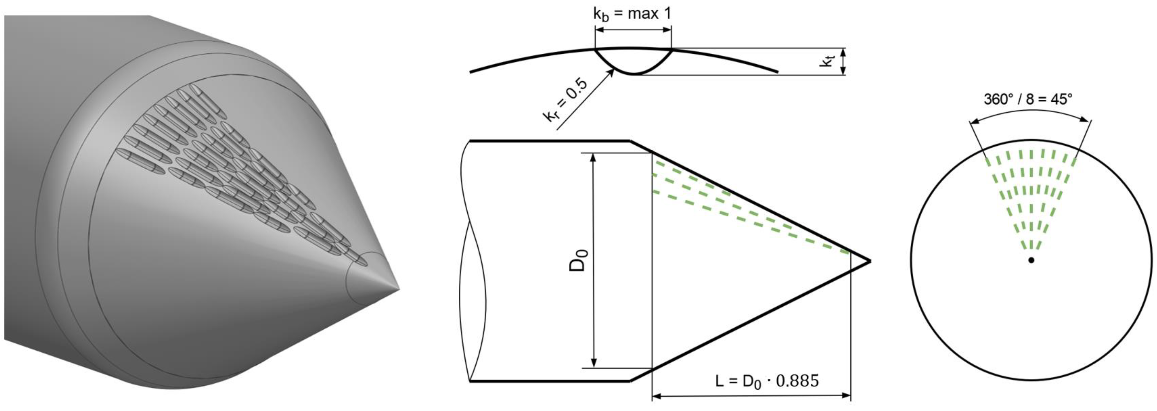
Figure 1. Partially grooved needle. Seat ring diameter D0 = 36.6 mm.
Energies 18 02725 g001
Figure 2. Partially and fully grooved seat ring (both step 4) and the definition of the depth of the grooves.
Energies 18 02725 g002
Figure 3. Three steps of the fully grooved needle.
Energies 18 02725 g003
Figure 4. Hill chart of the unmachined configuration (top left) and fully grooved needle at step 2 (top right). Efficiency for three machining steps at nED = 0.216 (bottom left) and efficiency losses for three machining steps (bottom right).
Energies 18 02725 g004
Figure 5. Efficiency of partially grooved needles and seat rings at nED = 0.216 (left) and efficiency losses (right) after four machining steps at 0°.
Energies 18 02725 g005
Figure 6. Efficiency of partially grooved needles and seat rings at nED = 0.216 (left) and efficiency losses (right) after four machining steps at 90°.
Energies 18 02725 g006
Figure 7. Efficiency of fully grooved needles and fully grooved seat rings at nED = 0.216 (left) and efficiency losses (right) after four machining steps of the seat ring and three steps of the needle.
Energies 18 02725 g007
Figure 8. Superposition of efficiency drops of the partially machined needle and seat ring both at 90°. Four steps of individual defects and the last step for the combination of both at nED = 0.216, QEB = 0.050 (left), QEB = 0.105 (center), QEB = 0.160 (right).
Energies 18 02725 g008
Figure 9. Partially (left) and fully grooved needle (right). Linear increase in efficiency losses for partial, nominal, and full load operation.
Energies 18 02725 g009
Table 1. Measured hill charts for machined needles, seat rings, and combinations of both.
Needle (N)
Machining Step (S)
Seat Ring (M)
Machining Step (S)
CommentsNumber of Measured Hill Charts
N 1, S 0–4M 0Partial grooves at 0°5
N 1, S 0–4M 0Partial grooves at 90°5
N 0M 1, S 0–4Partial grooves at 0°5
N 0M 1, S 0–4Partial grooves at 90°5
N 1, S 4M 1, S 4Partial grooves at 0° (both)1
N 1, S 4M 1, S 4Partial grooves at 90° (both)1
N 2, S 0–3M 0Fully grooved needle4
N 0M 2, S 0–4Fully grooved seat ring5
N 2, S 3M 2, S 4Fully grooved both1
Disclaimer/Publisher’s Note: The statements, opinions and data contained in all publications are solely those of the individual author(s) and contributor(s) and not of MDPI and/or the editor(s). MDPI and/or the editor(s) disclaim responsibility for any injury to people or property resulting from any ideas, methods, instructions or products referred to in the content.