Article

Model of a Switched Reluctance Generator Considering Iron Losses, Mutual Coupling and Remanent Magnetism

1
HEP-ODS Elektra Zadar, 23000 Zadar, Croatia
2
Department of Power Engineering, Faculty of Electrical Engineering, Mechanical Engineering and Naval Architecture, University of Split, 21000 Split, Croatia
*
Author to whom correspondence should be addressed.
Energies 2025, 18(10), 2656; https://doi.org/10.3390/en18102656
Submission received: 25 April 2025 / Revised: 15 May 2025 / Accepted: 19 May 2025 / Published: 21 May 2025

Abstract

In this paper, an advanced model of a switched reluctance generator (SRG) with mutual coupling, iron losses, and remanent magnetism is presented. The proposed equivalent circuit for each SRG phase is represented by the winding resistance, phase inductance and electromotive forces (EMFs) induced by mutual flux-linkage and remanent magnetism. In the advanced SRG model, the phase inductance and equivalent iron-loss resistance need not be known, as the components of the phase current flowing through them are determined directly from appropriate look-up tables, making the advanced SRG model simpler. Both the magnitude of the mutual flux-linkage and its time derivative are considered in the advanced model. The proposed model only requires knowledge of data that can be obtained using the DC excitation method and does not require knowledge of the SRG material properties. For the first time, the remanent magnetic flux of the SRG is modeled and the induced EMS caused by it is included in the advanced SRG model. Stray losses within the SRG are considered negligible. Connection to an asymmetric bridge converter is assumed. Magnetization angles of individual SRG phases are provided by the terminal voltage controller. The results obtained with the advanced SRG model are compared with experiments carried out in the steady-state of the 8/6 SRG with a rated power of 1.1 kW SRG over a wide range of load, terminal voltage, turn-on angle, and rotor speed in single-pulse mode suitable for high-speed applications.

1. Introduction

Geometric simplicity, the absence of windings or permanent magnets on the moving part, lower manufacturing costs, greater reliability and robustness compared to other electrical machines are the main characteristics of switched reluctance machines (SRM) [1,2]. As the windings are not located on the moving part but only on the stator of the machine, cooling is facilitated, as the moving part does not heat up due to copper losses. The SRM has no permanent magnets or windings on the moving part, which simplifies the design, but unlike most other electrical machines, it requires a power converter. The lack of permanent magnets and windings on the rotor allows efficient operation at high speeds and high temperatures, but also brings many challenges, such as high torque ripple, noise, and vibration. It is possible to mitigate these issues by using different algorithms to control the machine with the power converter. A system with an SRM requires precise knowledge of the rotor position in order to magnetize the phases in time. Due to its simple design, an SRM is cheaper to manufacture than other electrical machines. Also, it should bear in mind that the final price of a product also includes the price of the power converter and very often the price of the incremental encoder.
SRMs are usually designed for rotary motion, although they can also be designed for linear motion [3,4]. SRMs designed for circular motion consist of a stator and a rotor, both of which have salient poles. The number of poles on the stator and rotor is usually not identical. Each of the stator poles has a winding, while the rotor poles are not wound.
The conventional SRM model is based on the assumption that the individual phases of the machine are magnetically decoupled from each other. The starting point is therefore the voltage equation of one phase of the machine, whereby mutual coupling effects, remanent magnetic flux, iron losses, and stray losses are neglected. The models of all individual phases of the machine result in the overall SRM model. To create such a model, it is necessary to know the resistance of the phase windings and the magnetic characteristics of the machine. The resistance can be measured relatively easily, while the magnetic characteristics require knowledge of the flux-linkage or phase inductance for different values of phase currents and rotor positions. They can be determined using the finite element method (FEM) [5,6,7,8,9] or experimentally [10,11,12]. According to [13], there are five methods that can be used to experimentally determine the magnetic characteristics of SRMs: the direct current (DC) excitation method, the alternating current (AC) method, the AC superposition method, the current interruption method, the chopped current method, and the torque method. The DC method is satisfactorily accurate and simple, which is why it is widely used. The dependence of the phase flux-linkage or inductance on the phase current and rotor position is usually written as a second-order partial sum of the Fourier series [7,14]. In addition, it is possible to write them with other equations [15], store them in a look-up table [16] or map them with a neural network [17,18,19]. It is also possible to calculate the flux-linkage using the FEM in each iteration of the program to determine the current values of the SRM variables [20].
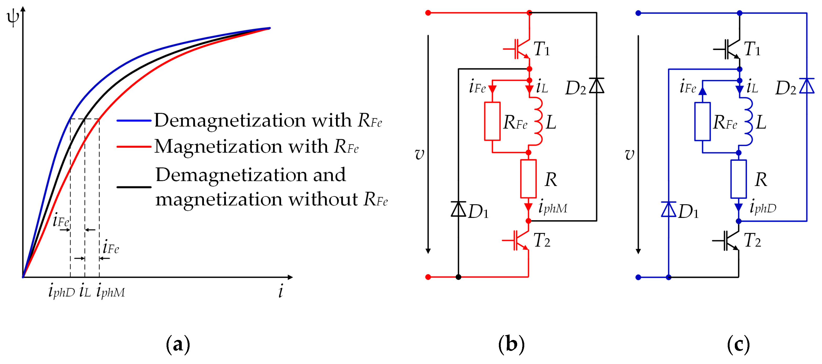
In most models, the iron losses are neglected, although they can account for up to 50% [21] or up to 33% [22] of the SRM losses. If the characteristics of the material of which the machine is made are known, it is possible to calculate the magnetic field with FEM and determine the iron losses [22,23]. In [11,24], it was proposed to improve the SRM model by introducing an equivalent resistance parallel to the phase inductance and thus modeling the iron losses without knowing the material characteristics.
In most papers, the effect of mutual coupling between the SRM phases is neglected. Nevertheless, models were created in [8,9,10,14] that take mutual coupling into account. In [
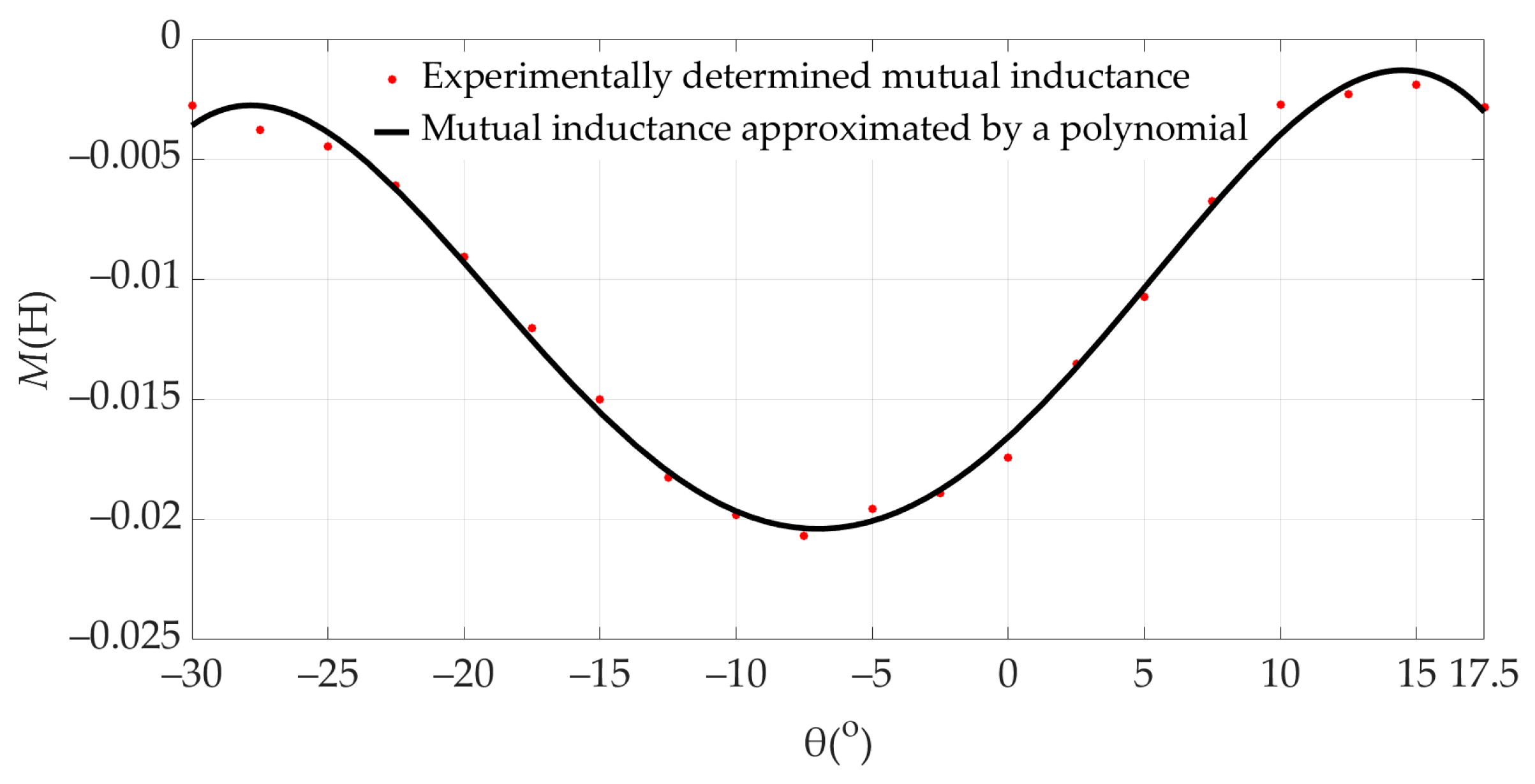
10], it was shown that the effect of mutual coupling can lead to asymmetries between the phase currents. Furthermore, this paper does not consider the time derivative of the mutual flux-linkage, but only the magnitude of the mutual flux-linkage. In [8,9,14], the FEM was used to calculate the mutual coupling effect. This method requires knowledge of the detailed geometry of the machine and the material properties, i.e., data that is not publicly available and must be obtained from the manufacturer. Since a considerable part of the flux-linkage of a phase is coupled via the poles of the neighboring phases, it is necessary to consider the effect of mutual coupling in the SRM model in order to calculate the instantaneous values of the phase currents, the flux-linkages, the electromagnetic torque of the SRM, etc., more accurately. When an SRM phase is magnetized in the same/opposite direction as the neighboring phase, the flux-linkage of the neighboring phase coupled by the phase under consideration is subtracted/added from the flux-linkage generated by the phase under consideration. It is desirable to achieve a configuration in which the flux-linkage of the neighboring phase is added to the flux-linkage of the considered phase because then the flux-linkages of all phases are symmetrical. This can be achieved if each phase of the machine is magnetized in the opposite direction to the neighboring phases. Such a configuration can be achieved with an SRM that has an odd number of phases.
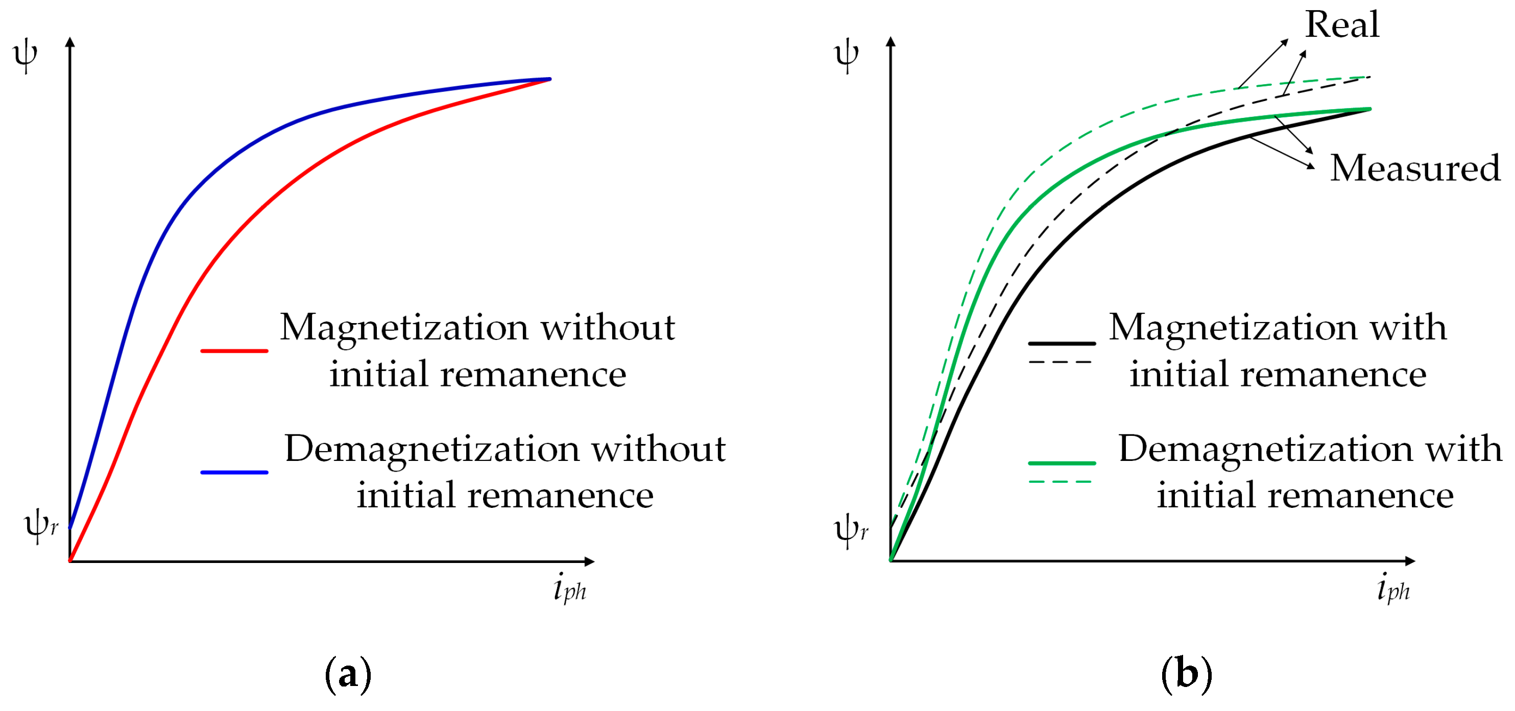
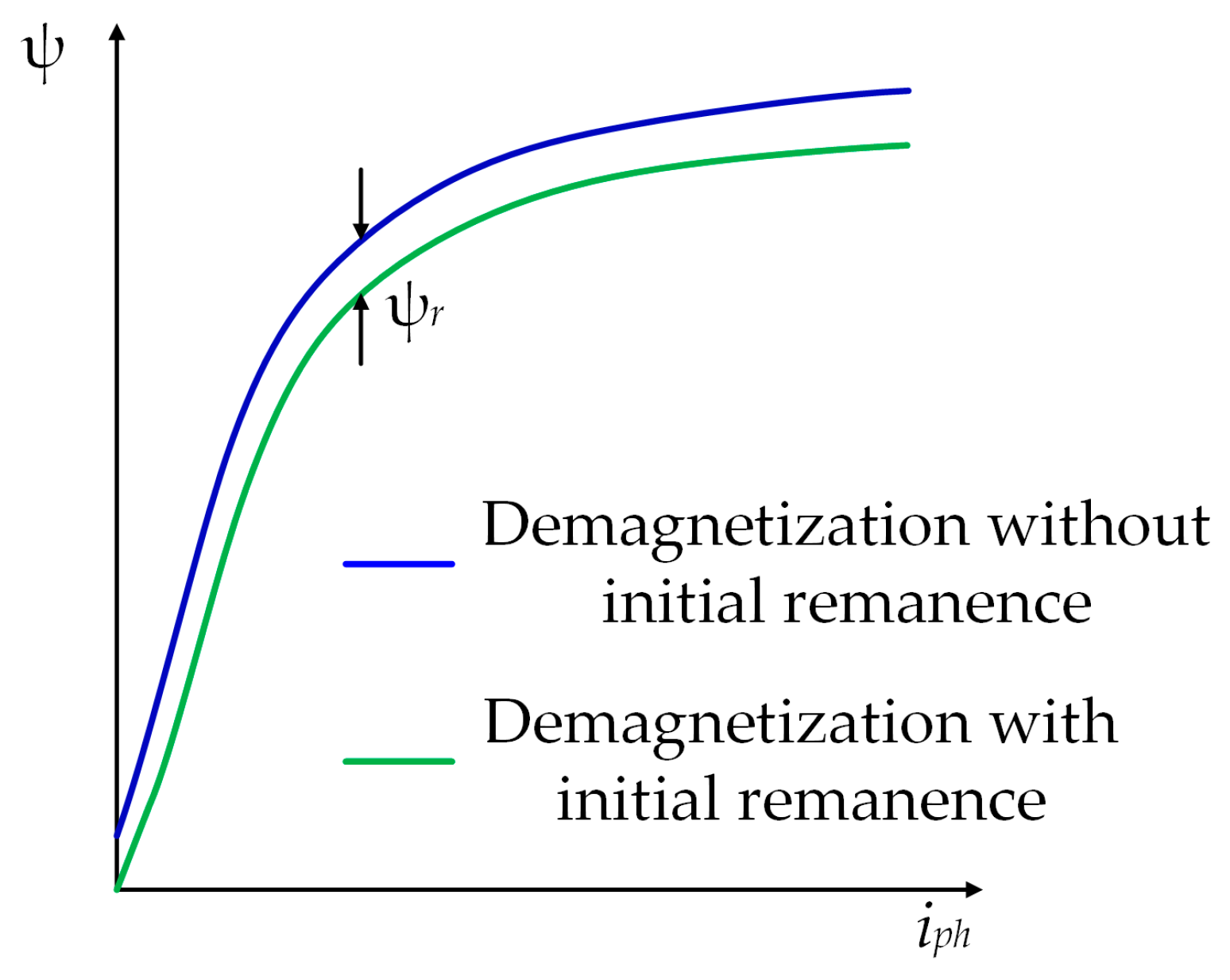
The remanent magnetic flux was neglected in all earlier publications. In [25], it was pointed out that the remanent magnetic flux is important and difficult to predict and model, and the need for further research was pointed out.
SRM is considered for the operation of generators in different areas. It is used for operation in wind turbines [26,27,28], as an electric starter and generator in the aerospace industry [29], and as a generator in wave power plants [30]. One of the main advantages of the switched reluctance generator (SRG) is that it can operate over a wide speed range and does not require a gearbox. The commercial application of the SRM was achieved in a 20 kW wind turbine [31]. In the aerospace industry, reliability in the event of failure is emphasized as an advantage. For example, if one phase fails, the other phases can continue to generate power so that the aircraft’s electrical systems continue to be supplied with electrical energy despite the failure.
In this paper, a new model of a four-phase SRG with mutual coupling of the neighboring phases, remanent magnetic flux and iron losses is presented. To model the mutual coupling between neighboring phases, an experimental approach similar to [10] was used, with the difference that in this paper both the magnitude of the mutual flux-linkage and its time derivative were considered. The proposed model requires only input data that can be obtained using the DC excitation method and does not require knowledge of the SRG material properties. The iron losses were calculated using the same equivalent circuit as in [11,24], with the difference that the equivalent resistance of the iron losses does not need to be known, but the SRG phase current component responsible for these losses was determined directly from a look-up table, which makes the advanced SRG model simpler. The remanent magnetic flux of the SRG was modeled for the first time and the induced EMS caused by it was included in the advanced SRG model. The accuracy of this model was experimentally verified in single-pulse operation and the justification for using the model was determined by comparison with the conventional SRG model. In this paper, the SRG is connected to the asymmetric bridge converter required for proper phase magnetization. The stray losses of the SRG are neglected. The mechanical losses are also not considered in the machine model itself. However, to obtain the experimental electromagnetic torque, these losses are subtracted from the measured mechanical torque. The resulting experimental electromagnetic torque, multiplied by the rotor speed, corresponds to the experimentally determined input power Pin,exp.

2. Control of the Switched Reluctance Generator

Figure 1 shows the cross-section of the SRG with eight poles on the stator and six poles on the rotor (8/6) with the rotor at the aligned position (Figure 1a) and unaligned position (Figure 1b). The magnetized phase winding and its flux-linkage lines are colored red.
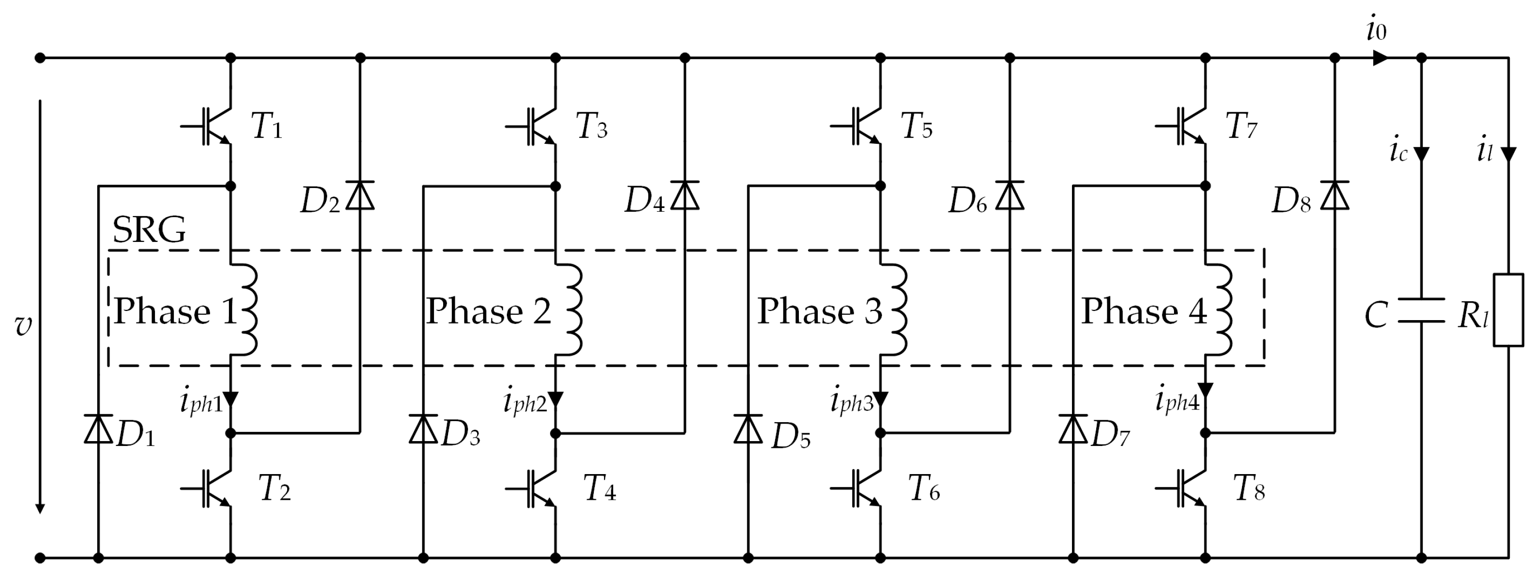
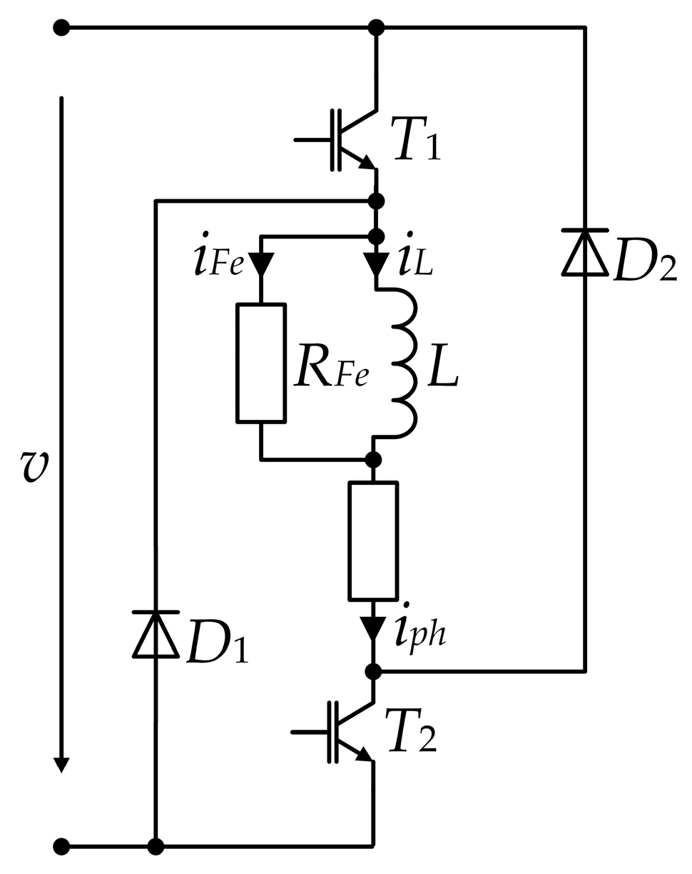
For an SRG to function, a power electronic converter is required. Numerous types of converters have been studied in the literature. The most common type of converter is the asymmetric bridge converter, as shown in Figure 2, with the four-phase SRG, the load resistance Rl, and the capacitor C, which has the task of supplying energy for the phase magnetization. In this configuration, each phase of the SRG can be controlled separately, which ensures tolerance to phase fault.
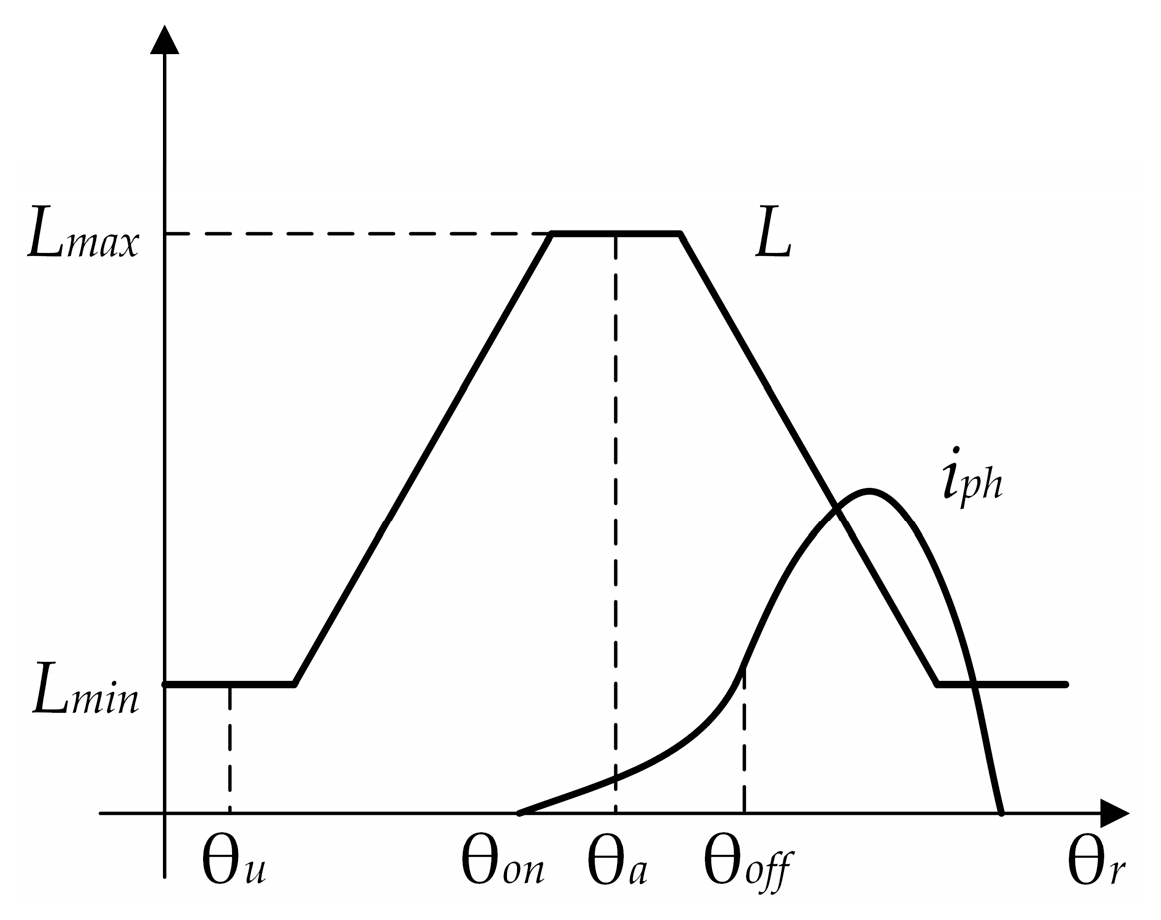
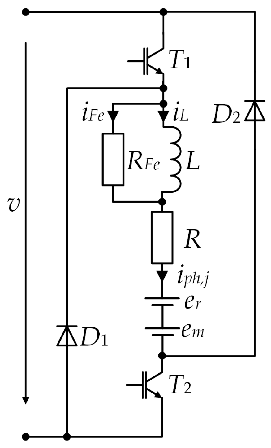
In this paper, two stages of SRG and converter are realized for each phase: magnetization and demagnetization (Figure 3). The waveforms shown in Figure 3 assume high-speed operation and linear analysis, which means that there is no magnetic saturation. Magnetization starts when the two transistors of the same converter leg are switched on (angle θon). During the magnetization of an SRG phase, the terminal voltage is applied to the magnetized phase and the phase current increases. The magnetization is completed at the time corresponding to the rotor position θoff shown in Figure 3 when the transistors are switched off. At this rotor position, the diodes in the same leg start to conduct the phase current and the phase inductance decreases, as shown in Figure 3.
In addition to magnetization and demagnetization, there is a third state, which was first proposed by [32] and is referred to as the freewheeling stage. In [27], this stage is incorrectly referred to as “flux boosting” because during this stage the flux-linkage remains approximately constant. The third stage is observed when only one of the transistors of the same leg is switched on and the other is switched off (for example, the current of phase 1 in Figure 1 flows through T1 and D2). The phase voltage is then zero. Applying the zero voltage to the phase reduces the current ripple of the terminal voltage. However, the output power is reduced [33]. Therefore, the third state was not used in this paper.
The phase current waveform shown in Figure 3 applies to high-speed operation, where the EMF is greater than the terminal voltage. This EMF causes the phase current to continue to rise even after θ
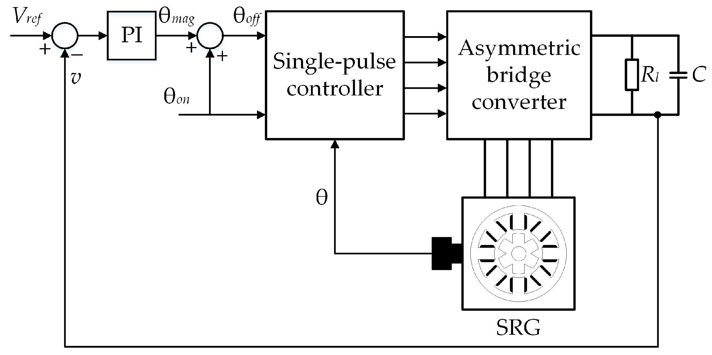
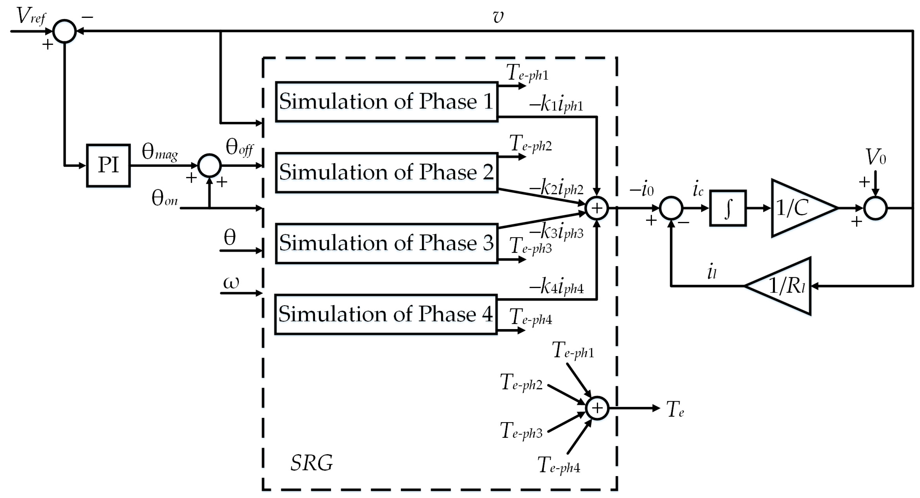
off, which can lead to a large uncontrolled phase current peak. One possible solution to avoid these peaks is the SRG terminal voltage control system shown in Figure 4. As in [34,35], the terminal voltage is also the controlled variable in this paper. In [34,35], the output of the PI controller is turn-off angle, but instead of this angle, the magnetization angle is used in this paper. Considering that there is an analytical expression for the turn-off angle and the magnetization angle when the turn-on angle is fixed, it is ultimately irrelevant which of these two angles is used as the output of the PI controller.
The single-pulse controller shown in Figure 4 determines the times at which the transistors of the same leg are switched on and off. If the rotor position is between θon and θoff, the two transistors of the same leg switch on, otherwise they switch off. The main purpose of the control system shown in Figure 4 is to validate the advanced simulation model of the SRG.

3. Conventional Mathematical Model of the SRG and the Asymmetric Bridge Converter

This section describes the conventional 8/6 SRG model connected to the asymmetric bridge converter and loaded by Rl. The parameters of the SRG can be found in Appendix A. In this model, each phase of the SRG is represented as a series-connected phase inductance L with the winding resistance R. Figure 1 shows the equivalent circuit of the four-phase SRG connected to the asymmetric bridge converter.
The diodes D1 and D2 and the IGBTs T1 and T2, which are shown in Figure 2, are modeled as ideal switches. The diodes and the transistors conduct alternately. When the transistors are switched on, phase magnetization begins, and when the transistors are switched off, the diodes conduct, and this process represents demagnetization. Therefore, and according to Figure 2, the following equation applies to one phase of the SRG:
k v = R i p h + d ψ ( i p h , θ ) d t
where k denotes the switching state of the transistors; v denotes the terminal voltage; iph denotes the phase current; R denotes the phase resistance; ψ denotes the flux-linkage; θ denotes the rotor position.
Equation (1) can be written in the following form:
k v = R i p h + ψ i p h d i p h d t + ψ θ ω
where ω (=dθ/dt) denotes the rotor angular speed.
The phase current can be derived from (2) and expressed as follows:
i p h = 1 ψ i p h 0 t k v R i p h ψ θ ω m d t + i p h ( 0 )
When the transistors are switched on, iph(0) = 0. Based on (3), the phase currents in all four phases of the machine are as follows:
i p h j = 1 ψ j i p h j 0 t k j v R i p h j ψ j θ ω m d t
where j (j = 1, …, 4) is the number of the phase.
The phase currents described by (4) are always positive. The terminal current shown in Figure 1 is
i 0 = j = 1 4 k j i p h j
The terminal current i0 is divided into the current iC, which flows through the capacitor C, and the current il, which flows through the load Rl. The current iC is therefore
i C = C d v d t = i 0 i l = j = 1 4 k j i p h j v R l
The terms ∂ψ/∂iph and ∂ψ/∂θ in (3) are still missing for a complete definition of the conventional mathematical model. Authors in [26,28] replace the flux-linkage in (3) as the product of the phase inductance and the phase current. Since the phase inductance changes periodically with the rotor position θ, it can be expressed as a Fourier series of the rotor position θ, which has current-dependent coefficients. Similarly, the Fourier series of the flux-linkage is expressed as a power series of the rotor position
ψ ( i p h , θ ) = l = 0 2 C l ( i p h ) cos ( N r l θ )
where Nr is the number of rotor poles.
The coefficients Cl (l = 0, 1, 2) in (7) are defined by the following equation:
C 0 ( i p h ) C 1 ( i p h ) C 2 ( i p h ) = 1 4 1 2 1 4 1 2 0 1 2 1 4 1 2 1 4 ψ a ( i p h ) ψ m ( i p h ) ψ u ( i p h )
where ψa(iph), ψu(iph), and ψm(iph) represent the flux-linkages in the aligned (θ = 0°), unaligned (θ = 180°/Nr), and midway position of the rotor (θ = 180°/2Nr), respectively.
The flux-linkages in (8) are approximated by polynomials [33]
ψ a ( i p h ) = l = 1 5 a a l i p h l , ψ m ( i p h ) = l = 1 5 a m l i p h l , ψ u ( i p h ) = a u i p h
where aal, aml, and au are the polynomial coefficients obtained by the curve fitting technique of the experimental data obtained by the DC excitation method [13]. These coefficients are listed in Appendix B.
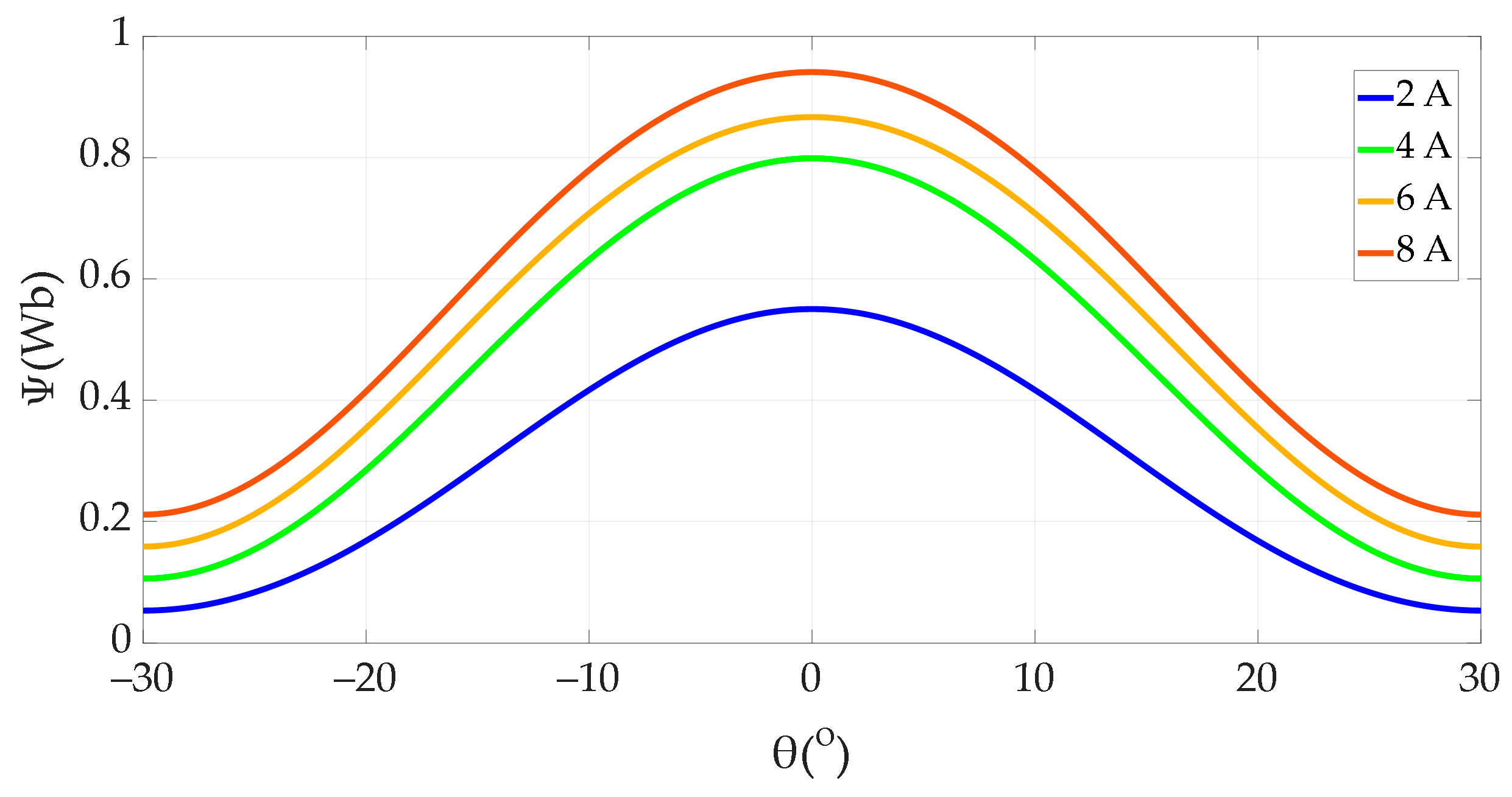
Substituting (8) and (9) into (7) gives
ψ ( i p h , θ ) i p h = 1 4 l = 1 5 l a a l i p h l 1 + 1 2 l = 1 5 l a m l i p h l 1 + 1 4 a u + 1 2 l = 1 5 l a a l i p h l 1 1 2 a u cos ( N r θ ) + 1 4 l = 1 5 l a a l i p h l 1 1 2 l = 1 5 l a m l i p h l 1 + 1 4 a u cos ( 2 N r θ )
The term ∂ψ/∂θ, which is needed in (3), can be obtained from (7)
ψ ( i p h , θ ) θ = N r l = 0 2 l C l ( i p h ) sin ( N r l θ )
Substituting (10) and (11) into (3), the phase current iph is completely determined. Using (7)–(9) and the polynomial coefficients given in Appendix B, it is also possible to determine ψ(iph,θ), as shown in Figure 5.
The electromagnetic torque of one phase is
T e = W c θ = 0 i p h ψ ( i p h , θ ) d i p h θ
where Wc is the magnetic co-energy.
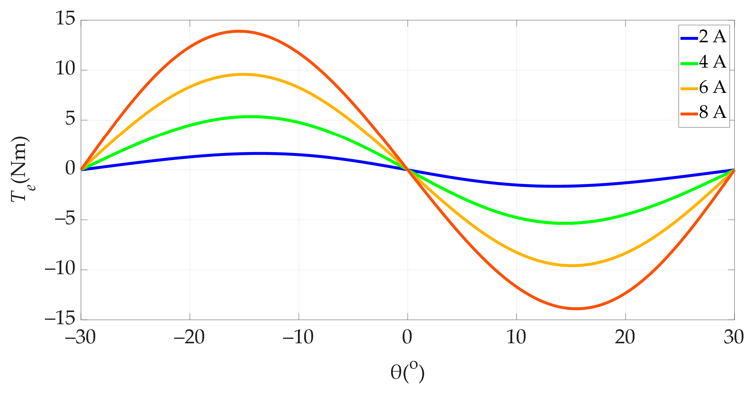
Using (7)–(9) and (12), the electromagnetic torque is defined as
T e ( i p h , θ ) = N r 2 sin ( N r θ ) l = 1 5 1 l + 1 a a l i p h l + 1 1 2 a u i p h 2 N r sin ( 2 N r θ ) 1 2 l = 1 5 1 l + 1 a a l i p h l + 1 + 1 4 a u i p h 2 l = 1 5 1 l + 1 a m l i p h l + 1
Using the polynomial coefficients given in Appendix A, the electromagnetic torque of a phase is obtained as shown in Figure 6.
A positive electromagnetic torque corresponds to the motor operating mode and a negative one to the generator operating mode, as shown in Figure 6.
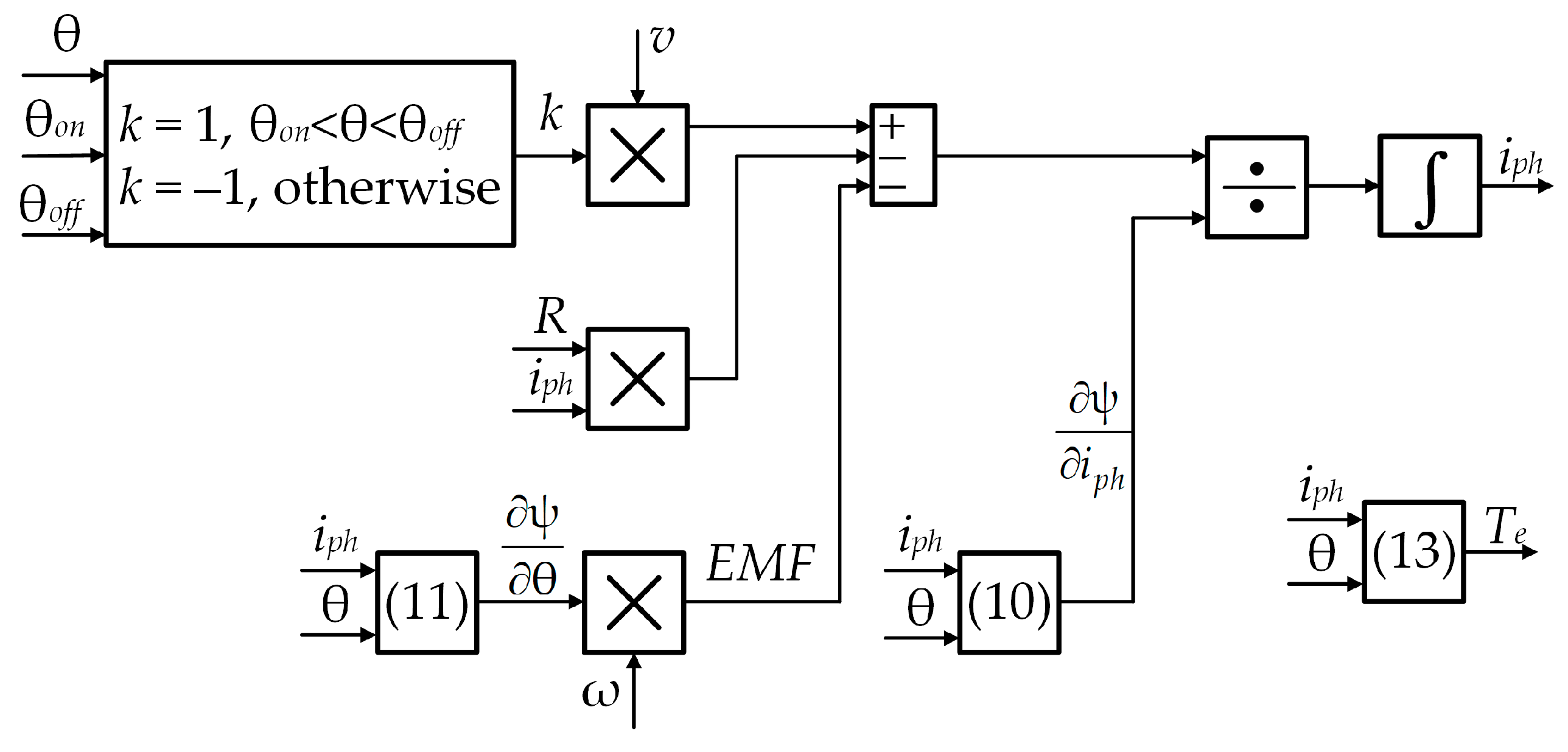
The full diagram of the conventional SRG model of one phase, which is basically a graphical representation of (3), is shown in Figure 7.
The diagram of the complete conventional SRG model together with the terminal voltage control system is shown in Figure 8.
As shown in Figure 8, the electromagnetic torque Te and the terminal current i0 are calculated based on the independent operation of the SRG phases.
The conventional SRG model does not take iron losses into account. This model provides symmetrical phase currents, and it was found in [10] that the phase currents of SRG are not symmetrical. These facts are the reason for the development of the advanced model presented in Section 4.

4. Advanced Mathematical Model of the SRG

This section presents a novel SRG model that considers iron losses, mutual inductances, and remanent magnetism.

4.1. Modeling of Iron Losses

When current flows through a phase winding, a flux-linkage is generated due to self-induction, which causes iron losses. To account for the iron losses in the model, it was suggested in [11,24] to add an iron loss resistor RFe in parallel to the inductance (Figure 9).
The phase current iph is divided into the current iL, which flows through the inductance, and the current iFe, which flows through the iron loss resistance. The current iL is responsible for generating flux-linkage, the current iFe for the iron losses. This section describes the determination of these two currents for different values of flux-linkages and rotor positions. iL and iFe are determined for 16 rotor positions, as in [10,19].
If there were no iron losses, the magnetization and demagnetization processes would follow the same curve when the rotor is locked (Figure 10a). However, considering that there are iron losses, this is not the case. Figure 10a shows the demagnetization and magnetization taking into account the iron losses. During magnetization, the current iphM flows through the phase winding so that iphM = iL + iFe, as shown in Figure 10b. The current iFe changes with the change in the flux-linkage ψ.
During demagnetization, the current iphD flows through the phase winding, which consists of the current iL minus the current iFe, so that iphD = iLiFe. As a result, the blue magnetization curve in Figure 10a shifts to the left by the amount iFe.
The following equations result from Figure 10a:
i L = i p h M + i p h D 2
i F e = i p h M i p h D 2
The DC excitation experiment was used to determine the current through the inductance and the current through the iron loss resistance for a given flux-linkage and position. The DC excitation experiment was performed for phase currents up to and above the rated current of 6 A and for 16 rotor positions from 0° to 30° with a step size of 2°. The dependencies of the current iL and iFe on the position and the flux-linkage are shown in Figure 11 and Figure 12.
Since the magnetization and demagnetization curves are close to each other, the current through the iron loss resistance determined experimentally using (15) exhibits a certain degree of measurement noise. Therefore, the data shown in Figure 12 was filtered beforehand. The physical conditions specified for the filter are described below. When the flux-linkage is 0 Wb, there are no iron losses and the current iFe is 0 A. On the other hand, when the flux-linkage is 1 Wb, the phase core is in deep magnetic saturation, so the magnetization and demagnetization curves practically overlap and the difference between them is 0 A again. The condition specified for the filter is, therefore, that the current iFe is equal to 0 A when the flux-linkage is 0 Wb and 1 Wb.

4.2. Mutual Coupling Effect

Due to the mutual coupling between the SRG phases, part of the flux-linkage of the neighboring phase of the SRG is coupled by the phase under consideration. The change in this flux-linkage induces a voltage in the phase under consideration. It is important to note that the neighboring phase, which is magnetized before the phase under consideration, already has a significant flux-linkage at the time when the phase under consideration is magnetized.
The mutual inductance between coupled phases is estimated using the DC excitation method, in which the phase voltage is measured at the open terminals of the phase under consideration and the neighboring phase is magnetized. The rotor is mechanically fixed in a desired position. The ultra-precise IT 60-S current transducer was used to measure the phase current of the SRG. This sensor was also used for the identification of iron losses described in Section 4.1.
This article assumes that the direction of rotation of the rotor is clockwise. In this case, the order of magnetization of the SRG phases is as follows: phase 1, phase 4, phase 3, phase 2 (Figure 13). For example, when phase 1 is magnetized, phase 2 is already magnetized. Figure 13 shows different rotor positions in which phase 1 is magnetized in each of the positions shown. The flux-linkage lines of phase 1 are shown in red. The flux-linkages lines of phase 2 and phase 4, which flow through phase 1, are also shown when these phases are magnetized. A turn-on angle of −10° was selected.
The position of the rotor of phase 1 in Figure 13a is −7.5°, and the current through phase 2 is significant. The flux-linkage lines of phase 2, which couple phase 1, are shown in black. In this rotor position, the magnetic resistance between phase 1 and phase 2 is minimal and the mutual inductance is maximum. The flux-linkage lines of phase 2, which couple phase 1, are shown as solid black lines.
The position of the rotor of phase 1 in Figure 13b is 10°. There is a magnetic coupling between phase 2 and phase 1, since the rotor position of phase 2 is 20° and its flux-linkage is not yet negligible. The flux-linkage lines of phase 2, which couple phase 1, are shown by solid black lines. After phase 1, as already mentioned, phase 4 is the next phase to be magnetized. The position of the rotor of phase 4 in Figure 13b is −5°. Since a turn-on angle of −10° was selected, phase 4 is magnetized. It should be noted that the current has only just started to flow through phase 4 and has not yet generated any significant flux-linkage. Therefore, the mutual coupling between phase 4 and phase 1 is negligible and the flux lines of phase 4, which couples phase 1, are represented by blue dashed lines.
Figure 13c shows the rotor position of phase 1, which is 25° and this phase is still magnetized. The rotor position of phase 4 is 10° and a considerable current flows through this phase. However, the coupling between phase 1 and phase 4 is negligible due to the high magnetic resistance.
Finally, from the considerations resulting from the three different rotor positions shown in Figure 13, it can be concluded that it is justified to consider only the mutual coupling of a certain phase and the previously magnetized phase when modeling the mutual coupling. To determine the induced EMFs due to the coupling effect, the direction of the flux-linkage of each phase must be considered. Part of the flux-linkage of phase 2, which couples phase 1, is in the opposite direction of the flux-linkage of phase 1. The same applies to phase 3 and phase 2 or phase 4 and phase 3. In contrast, part of the flux-linkage of phase 4, which couples phase 1, is in the same direction as the flux-linkage in phase 1. The flux in a certain phase caused by the jth phase current is therefore as follows:
ψ j 1 , j = i p h j M , j = 2 , 3 , 4 ψ j + 3 , j = i p h j M , j = 1
where M is the mutual inductance between a certain phase and previously magnetized phase.
The experimentally determined mutual inductance and its polynomial interpolation are shown in Figure 14.
The equation of the polynomial describing the mutual inductance shown in Figure 14 is as follows:
M = l = 0 4 m l θ l
where the polynomial coefficients ml (l = 0, …, 4) were determined using the Matlab Basic Fitting Tool and are listed in Appendix C.
By deriving the flux-linkages in (16) as a function of time and considering (17), the induced EMF caused by the jth phase is calculated as follows:
e m = e j 1 , j = d ψ j 1 , j d t = d i p h j d t M + i p h j d M d t = d i p h j d t M + i p h j d M d θ d θ d t =   = d i p h j d t l = 0 4 m l θ l + i p h j l = 0 4 l m l θ l 1 180 π ω , j = 2 , 3 , 4 e j + 3 , j = d ψ j + 3 , j d t = d i p h j d t M + i p h j d M d t = d i p h j d t M + i p h j d M d θ d θ d t =   = d i p h j d t l = 0 4 m l θ l + i p h j l = 0 4 l m l θ l 1 180 π ω , j = 1
In (18), the rotor position is expressed in degrees. To express the rotor speed ω in rad/s, the factor 180/π appears in (18).

4.3. EMFs Induced by Remanent Magnetism

During the periodic magnetization and demagnetization of the SRG phases, remanent magnetism (or remanence) remains in the SRG iron. This remanence produces the remanent flux ψr. Only a part of this remanent magnetism present in the SRG rotor induces an EMF in the phases of the SRG when the rotor rotates. In this paper, it is assumed that half of the total remanence belongs to the rotor and that this part is responsible for the EMF induced by the remanent flux.
In order to obtain the EMF caused by the remanent flux in a phase, factors on which the remanent flux depends and a method for its determination must be defined. Similar to Section 4.1 and Section 4.2, the DC excitation method is chosen to determine the remanent flux. For this purpose, it is necessary to carry out magnetization and demagnetization with and without remanence. The elimination of remanence is achieved by applying a decaying AC voltage to one phase. Figure 15a shows the measured flux-linkage of a phase during magnetization and demagnetization when the rotor is locked and the initial remanence has been eliminated. During this experiment, the stator current should be higher than the rated current to achieve maximum remanent magnetic flux. At the beginning of this experiment, the remanent magnetic flux is zero. When the machine phase is magnetized, the remanent magnetic flux increases. At the moment when the machine phase starts to demagnetize, the remanent magnetic flux has a value of ψr, which is the maximum possible value for the given rotor position. It is assumed here that the remanent magnetic flux remains constant during the demagnetization process (blue curve in Figure 15a). The remanent magnetic flux ψr is difficult to determine accurately from the data obtained with this method because when the phase current approaches zero, the measurement noise begins to dominate. The method for determining the remanent magnetic flux ψr, which avoids this problem, is described below.
When the DC experiment is completed without remanence, it is necessary to repeat this experiment, but this time with remanence. In this case, it is assumed that the remanent magnetic flux has a constant value ψr during the experiment. Therefore, the remanent magnetic flux has no influence on the induced electromotive force and cannot be recorded in the second experiment (curves in Figure 15b, marked with a solid line). In contrast, the real magnetization and demagnetization characteristics are marked by dashed lines in Figure 15b.
In both experiments (without and with initial remanence), the remanent magnetic flux during demagnetization has the same value ψr. The demagnetization curve of the experiment without initial remanence contains the maximum of the remanent magnetic flux ψr, while the demagnetization curve of the experiment with initial remanence does not. Figure 16 shows the demagnetization curves from Figure 15. The difference between these two curves was determined with a step of 0.5 A in the range from 0 A to 10 A, and thus the remanent magnetic flux ψr was obtained for a specific rotor position.
In this paper, ψr was determined for rotor positions from 2° to 30° with a step of 2°. Figure 17 shows the experimentally determined remanent magnetic flux and its linear approximation as a function of the rotor position. The remanent magnetic flux has a maximum value ψrmax = 0.0314 Wb at the aligned rotor position (θ = 0°). For positions from −30° to 0°, ψr is mirror-symmetrical with respect to the ordinate axis in Figure 17.
The linear equation describing the dependence of the remanent magnetic flux ψr coupled by the phase under consideration on the rotor position is as follows:
ψ r ( θ ) = ψ r m a x ( 0.033 sgn ( θ ) θ + 1 )
All of the above applies to a locked rotor and with equal contributions from the stator and rotor to the remanent magnetic flux. The phase currents of the SRG are DC and the remanent magnetic flux in the stator (in the yoke and in each of the poles) always maintains the same direction. In this paper, we assume that it also maintains its maximum value. Therefore, the induced electromotive force in each phase winding is only due to the remanence in the rotor.
It is assumed that the stator and rotor poles contribute equally to the remanent magnetic flux, so that the maximum remanent magnetic flux of the rotor pole is 0.5ψrmax. As the rotor rotates, the remanent magnetic flux of the rotor pole changes under the influence of the magnetic flux of the phases it passes. A rotor pole is only in a certain position for a short time. For this reason, it can be assumed that each of the phases of the machine only partially changes the remanent magnetic flux of the rotor pole in the direction of its flux-linkage and not completely, as is the case in the DC excitation experiment with the locked rotor. Figure 18 shows the change in the remanent magnetic flux in the rotor as a function of its position. The arrows on the rotor represent the remanent magnetic flux in the rotor pole, while the arrows on the stator pole represent the flux-linkage of each phase when magnetized. The rotor rotates clockwise. The sign of the remanent magnetic flux is determined by the direction of the flux-linkage of a particular phase. If these directions coincide, the remanent magnetic flux is positive, otherwise it is negative. This designation of the sign of the remanent magnetic flux of the rotor pole is made taking into account the fact that in the equivalent SRG scheme shown later, the positive-induced EMF counteracts the increase in the phase current and the negative one supports the increase in the phase current.
Furthermore, the process of changing the direction of the remanent magnetic flux in the rotor pole is naturally continuous and changes from 0.5ψrmax (when the rotor pole is in the phase 4 zone of influence) to −0.5ψrmax (when the rotor pole is in the phase 1 zone of influence), as shown in Figure 18. For simplicity, this change is modeled as discrete and it is assumed that the remanent magnetic flux of the rotor does not change in the zone of influence of the observed phase (rotor position from −30° to 30°), but only when the rotor pole leaves this zone. It is also assumed that each phase has the same influence on the change in the remanent magnetic flux of the rotor pole. Starting from the zone of influence of phase 1 via the zones of influence of phases 2 and 3 to the zone of influence of phase 4, the change in the remanent magnetic flux is modeled as a discrete change in three steps, with the step size being 1/3ψrmax. Therefore, the remanent magnetic flux in the zone of influence of phase 2 is (−1/3)·0.5ψrmax and in the zone of influence of phase 3 1/3·0.5ψrmax, as shown in Figure 18.
Considering all the above facts the remanent magnetism in the rotor of the jth phase of the SRG is calculated by the following equation:
ψ r , j ( θ ) = ψ r m a x , j ( 0.033 sgn ( θ ) θ + 1 )
where j = 1, …, 4, ψrmax,1 = –0.5ψrmax, ψrmax,2 = –0.5/3ψrmax, ψrmax,3 = 0.5/3ψrmax, ψrmax,4 = 0.5ψrmax.
Considering (20), the induced EMF due to the remanent magnetism in the rotor for the jth phase of the SRG is calculated by the following equation:
e r = d ψ r , j ( θ ) d t = d ψ r , j ( θ ) d θ d θ d t = ψ r m a x , j ( 0.033 sgn ( θ ) ) 180 ° π ω
The factor 180/π appears in (21) for the same reason as in (18). Equation (21) applies equally to the rotor pole under consideration and to all other rotor poles. The EMFs calculated by (18) and (21) are used to obtain the advanced equivalent circuit of the SRG, which is described in the next section.

4.4. Advanced Equivalent Circuit of the SRG

Figure 19 shows the equivalent circuit of one phase of the SRG, taking into account the iron losses, the EMF caused by the mutual coupling, the EMF caused by the remanent magnetism and the switching elements of the asymmetric bridge converter.
The following equation applies to the phase current iph:
i p h = i L + k i F e
where k denotes the switching state of the transistors.
During magnetization, k = 1 and the transistors shown in Figure 19 are switched on. The phase current iph therefore consists of the current through the inductance iL, increased by the current iFe, which flows through the equivalent resistance of the iron losses. During demagnetization, k = −1 and the transistors shown in Figure 19 are switched off. The phase current therefore consists of the current through the inductance, reduced by the current flowing through the equivalent resistance of the iron losses.
The following equation applies to the equivalent circuit shown in Figure 19:
k v = R i p h + d ψ d t + e r + e m
The flux-linkage, from (23), is
ψ = 0 t ( k v R i p h e r e m ) d t + ψ ( 0 )
Since the SRG operates in single-pulse mode, the flux-linkage at the time the transistors are switched on is 0 Wb, i.e., ψ(0) = 0 Wb.
The complete diagram of the advanced model of the jth phase of the SRG, which was realized in Matlab/Simulink, is shown in Figure 20.
The complete diagram of the advanced SRG model with the terminal voltage control system is similar to that shown in Figure 8, with the difference that in this case the blocks labeled Simulation of phase 1, …, Simulation of phase 4 are based on the advanced model of the jth phase shown in Figure 20.

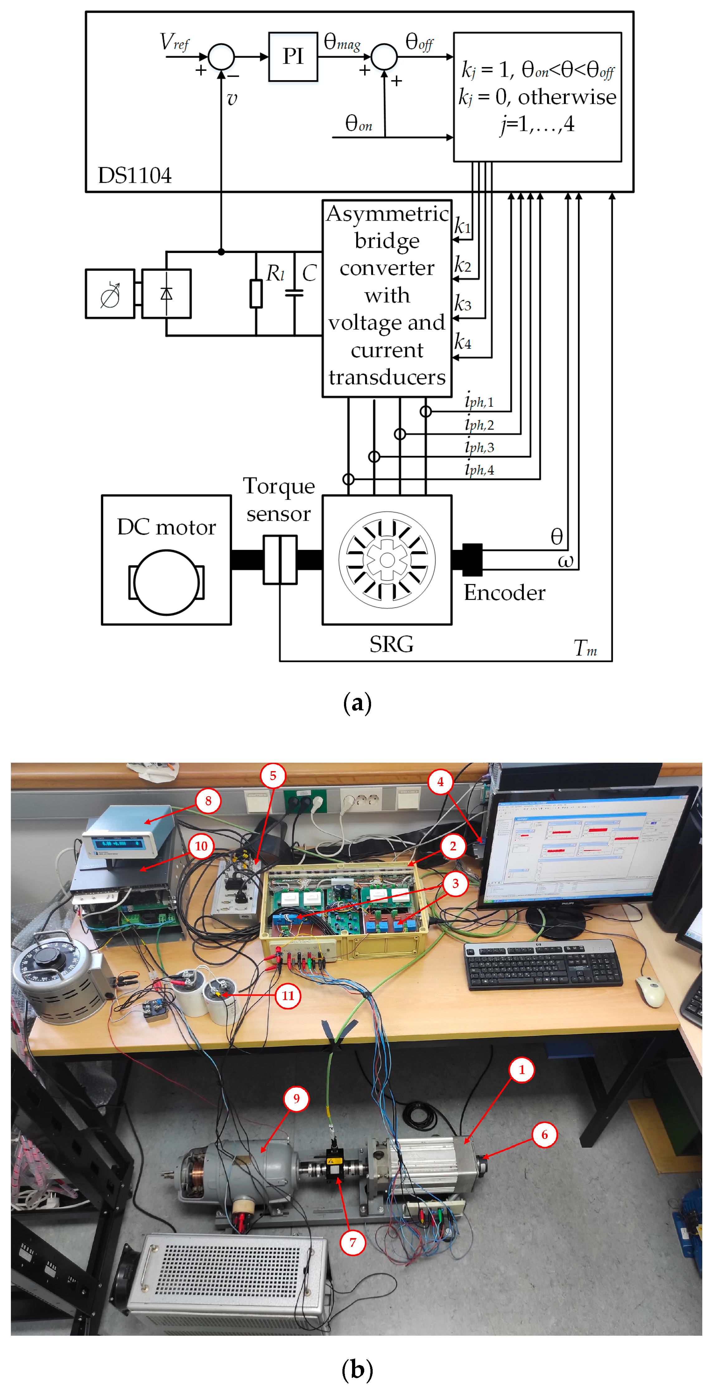
5. Experimental Validation of the Advanced SRG Model

The experimental setup of the SRG control system used for the evaluation of the proposed advanced SRG model is shown in Figure 21a, and the photo of the experimental setup is shown in Figure 21b.
The names and data of the main components of the experimental setup shown in Figure 21b are listed in Table 1.
A series of experiments were conducted to determine the accuracy of the advanced SRG model. By combining rotor speeds of 2000 rpm and 3000 rpm, terminal voltages of 150 V, 200 V, 250 V, and 300 V, load resistances of 110 Ω, 65 Ω, and 45 Ω and turn-on angles of −15°, −10°, and −5°, 58 steady-state operating points were realized with the laboratory setup. The SRG was tested over a wide power range, from 18.6% to 126.6% of the rated power.
The DS1104 controller board was used for the real-time implementation of the control algorithm shown in Figure 21 and for data acquisition. The control algorithm works reliably (i.e., without task overrun) up to a sampling frequency of 20 kHz, so this frequency was used. The parameters of the PI controller were determined by trial and error, using the integration gain Ki = 5 and the proportional gain Kp = 1.
For each operating point, the no-load torque was subtracted from the measured mechanical torque to obtain the electromagnetic torque Te generated by the SRG. To ensure the accuracy of the no-load torque measurement, the measurement was carried out in the range from 0 to 3000 rpm with an increment of 250 rpm and the measurement was repeated five times at each speed.
After conducting the experiments, simulations were carried out in Matlab/Simulink using the conventional and advanced model described in Section 3 and 
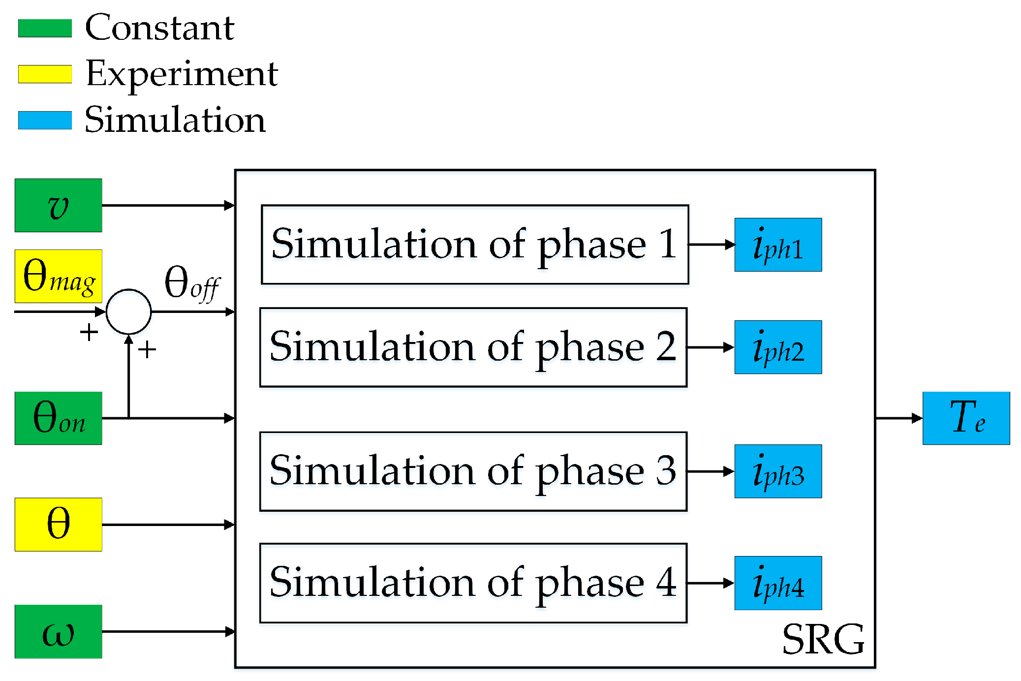
Section 4. The simulated phase currents and input powers were used for comparison with the corresponding measured values. The comparison is only possible if the simulations with the advanced and conventional model were carried out under the same conditions as the experiments. This means that the terminal voltage, the rotor speed, the turn-on and turn-off angles, and the rotor position must always be identical in the simulation and in the measurement. For this purpose, the so-called hybrid simulation model for steady-state conditions was developed, the diagram of which is shown in Figure 22.
Note that the blocks labeled Simulation of phase 1, …, 4 in Figure 22 may represent conventional or advanced simulation models of the SRG phases. The turn-on angle shown in Figure 22 was selected as constant, as this angle was also constant in experiments. The terminal voltage v was precisely controlled by the PI controller (Figure 21) and considering a capacitor of 8800 μF, its ripple was less than 0.5% in experiments. Therefore, it is justified to consider the terminal voltage as constant, as shown in Figure 22. The same applies to the rotor angular speed ω, which is controlled by the power converter.
In order to determine the accuracy of the conventional and advanced SRG simulation models, a simulation with a hybrid simulation model was also carried out for each of the 58 steady-state experimental operating points. The comparison of the experimentally determined phase currents with the phase currents obtained by the hybrid model, in which the phase currents were simulated by the advanced/conventional model, was carried out for a time of 4.75 s (95,000 samples) in the steady-state of the SRG. Each steady-state operating point of the SRG is completely defined by the load resistance Rl, turn-on angle θon, the rotor speed n (in rpm) and the terminal voltage v. Therefore, the so-called accuracy coefficient is defined by the following equation:
K ( R l , θ o n , n , v ) = q = 1 95 , 000 i p h , e x p ( q ) i p h , c o n v ( q ) q = 1 95 , 000 i p h , e x p ( q ) i p h , a d v ( q )
where iph,exp(q) denotes the experimental value of the phase current at the qth sampling instant and iph,conv(q)/iph,adv(q) denotes the phase current obtained with the conventional/advanced simulation model current at the qth sampling instant.
According to (25), the advanced model is more accurate than the conventional model if K > 1. Otherwise, the conventional model is more accurate.
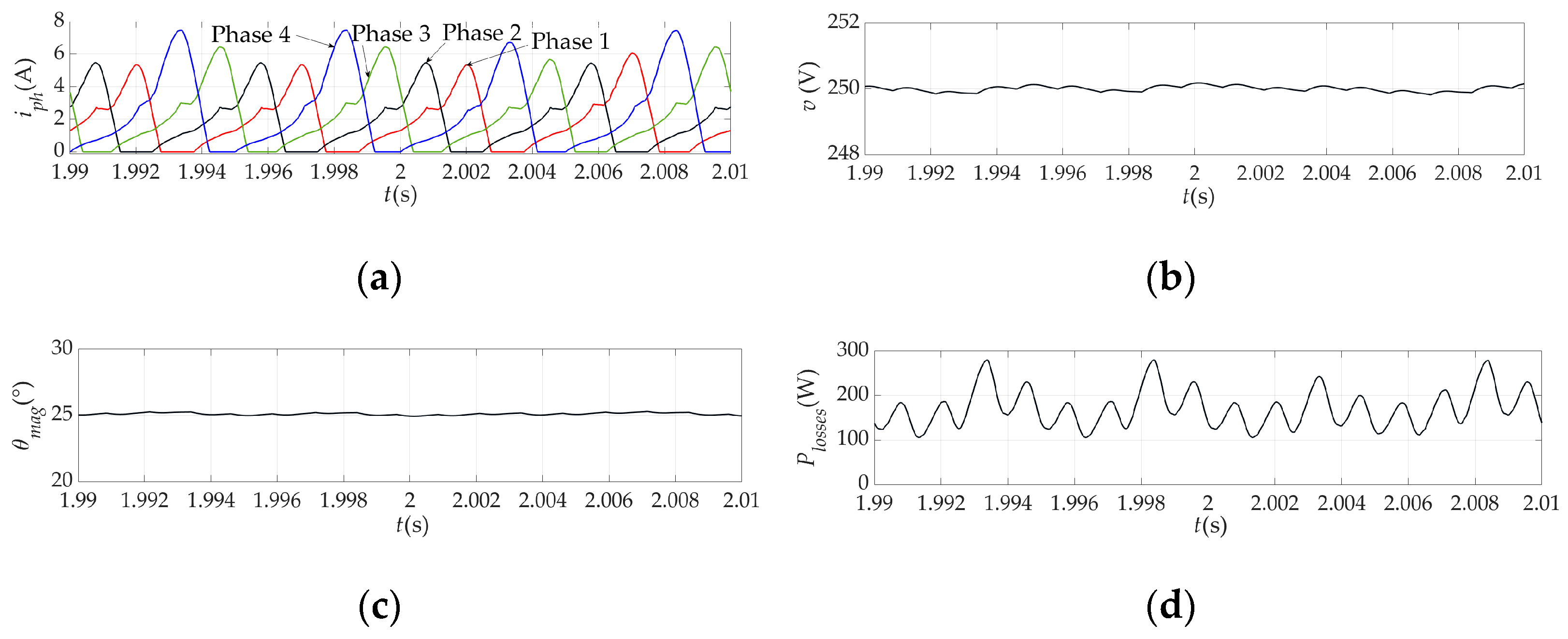
Figure 23 shows the phase currents and the magnetization angle for one of the 58 steady-state operating points defined by the following parameters: Rl = 65 Ω, θon = –5°, n = 2000 rpm and v = 250 V. The simulated phase currents are determined using the hybrid steady-state simulation model, in which the phase current models are first based on the conventional model and then on the advanced model. The same figure also shows the experimentally determined phase currents in the control system shown in Figure 21. According to Figure 22, the magnetization angle is the same for all these phase currents and corresponds to the experiment.
In Figure 23, it is easy to see that the phase currents obtained by the advanced simulation model of the SRG are in better agreement with the experimental phase currents. As already mentioned, the accuracy coefficient K according to Equation (25) was chosen as a measure of this agreement. The accuracy coefficient for each phase of the SRG and for each of the 58 steady-state operating points is shown in Figure 24.
Figure 24 shows a total number of 232 accuracy coefficients (58 × 4). The accuracy coefficient is greater than 1 in 226 cases, while it is less than 1 in 6 cases (points circled with a red line). This means that the phase current determined with the advanced simulation model is more accurate than that determined with the conventional model in 97.4% of cases. At the points where the accuracy coefficient is less than 1, in phases 2 and 3, it is possible in experiments that the remanent magnetic flux and the part of the flux-linkages of the neighboring phase cancel each other out. However, this cannot happen in the advanced model. In this case, the conventional model is more accurate than the advanced model, suggesting that discrete changes in remanent magnetic flux should be modeled more accurately. However, this modeling was not performed, as the number of such points is negligible.
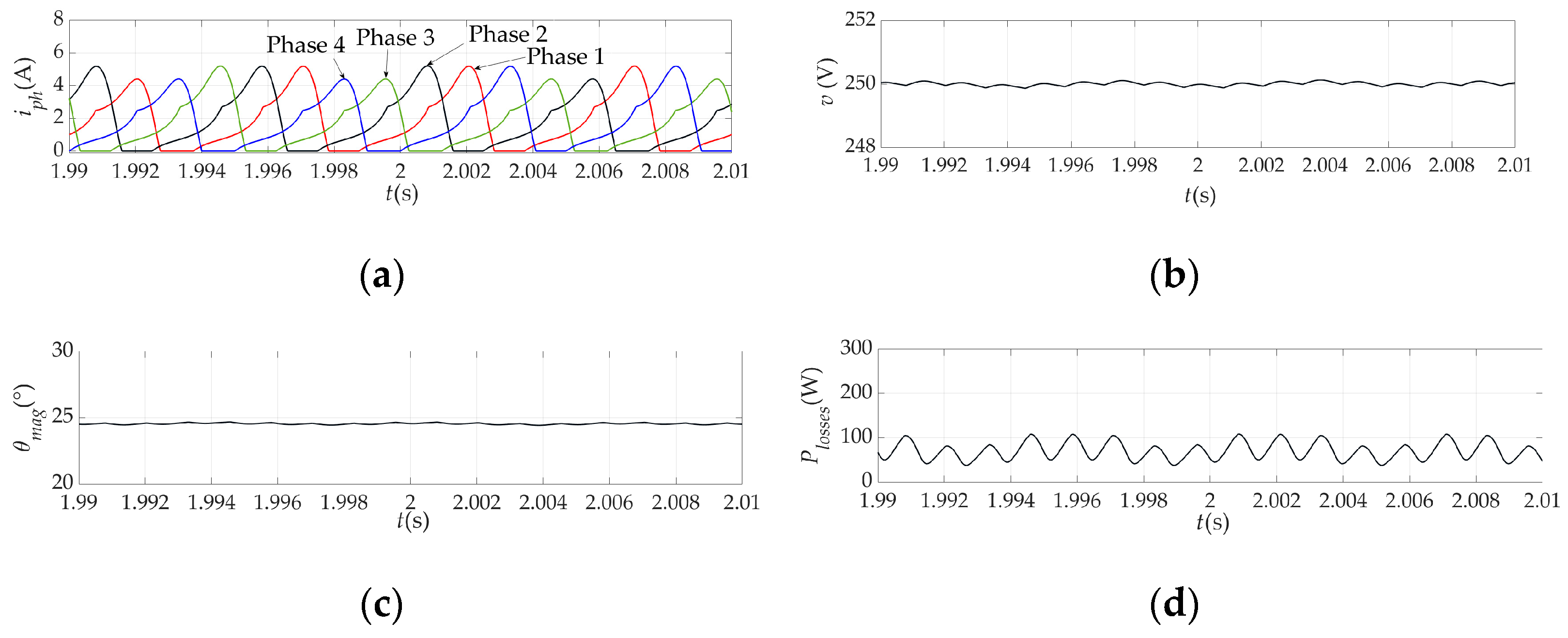
Finally, to show that the development of an improved SRG model is justified, Figure 25 and Figure 26 show the simulation results of the control system shown in Figure 4, where the SRG model is conventional (Figure 25) and advanced (Figure 26). These figures show simulation results for the same steady-state operating point as in Figure 21 (Rl = 65 Ω, θon = −5°, n = 2000 rpm and v = 250 V). Figure 25a and Figure 26a show the SRG phase current determined using the conventional and advanced models, respectively. As expected, the peak values of the phase currents are higher when using the advanced model, as the iron losses are also taken into account. Therefore, the losses calculated with the conventional model (copper losses), Figure 25d, are lower than the losses calculated with the advanced model (copper losses and iron losses, Figure 26d). In the advanced simulation model, the current of phase 4 has a higher peak value than the other phase currents. This effect was also observed in the experiment (Figure 23) and is due to the mutual coupling of phase 4 and its previously magnetized phase, i.e., phase 1. The flux-linkage of phase 1 is in the same direction as the flux-linkage of phase 4 and they support each other. As a result, the flux density of phase 4 is higher than that of the other phases and consequently the current of phase 4 is also higher.
The magnetization angle calculated with the advanced model (Figure 26c) is higher than that calculated with the conventional model (Figure 25c). There are physical reasons for this because in the SRG control system shown in Figure 4, the magnetization angle increases with the load. In this case, the iron losses actually represent an additional load. Finally, the terminal voltage shown in Figure 25b and Figure 26b has a ripple of less than 0.7%, so that the terminal voltage is practically constant. A similar ripple occurs with the rotor speed.
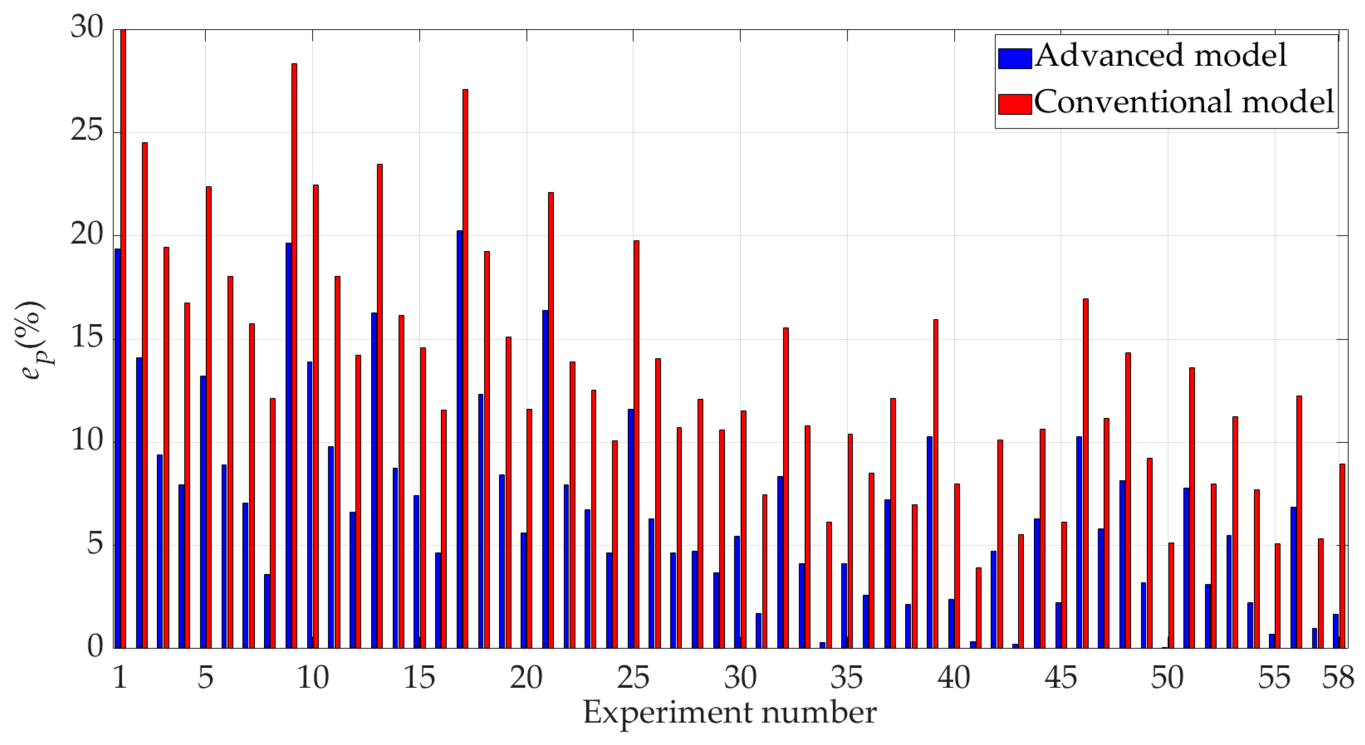
As a final step to check the accuracy of the simulation models, a comparison was made between the SRG input power calculated by the conventional and advanced simulation models and the experimentally determined input power for the same 58 steady-state operating points. The input power determined by the simulation was determined as the sum of the output power and the losses and not as the product of electromagnetic torque and power. This was performed because the electromagnetic torque is calculated according to (12), which implies a differentiation with respect to the rotor position and therefore contains a larger numerical error. It is important to emphasize again that the mechanical losses are not considered in the SRG model itself. These losses are subtracted from the measured mechanical torque to obtain the experimental electromagnetic torque, which is then multiplied by the rotor speed to obtain the input power Pin,exp.
The mechanical input power is measured by the torque transducer in the experiments. To compare the input powers, the relative difference eP between the experimentally determined input power and the input power calculated with the simulation models is defined by the following equation:
e P = P i n , exp P i n , s i m P i n , exp 100 %
where eP denotes the relative difference between the experimentally determined input power and the input power determined by simulation, Pin,exp denotes the experimentally determined input power, and Pin,sim denotes the input power determined by simulation (conventional or advanced model).
Figure 27 shows the relative differences between the input power of the SRG determined by simulations and the experimental power for 58 steady-state operating points.
The mean relative difference between the experimentally determined input powers and the input powers calculated with the advanced model in Figure 27 is 6.95%, and the mean relative difference between the experimentally determined input powers and the input powers calculated with the conventional model is 13.54%. It can also be seen that the advanced model is more accurate than the conventional model at all steady-state operating points. As the SRG output power increases, the accuracy of the advanced model also increases, so that it has the highest accuracy around the rated power and above the rated power of the SRG (points 3, 12, 16, 20, 24, 27, 30, 31, 34, 37, 38, 41, 44, 45, 47, 49, 50, 52, 54, 55, 57 in Figure 27) when the relative difference of the advanced model is between 0.05% and 7.96%. Despite this fact, the error of the advanced model is not zero, which means that the advanced SRG model does not fully describe the real SRG. The reason for this is that neither the semiconductor losses nor the so-called stray losses of the SRG were modeled. However, based on the data sheet of the diodes and transistors used in the experiments, the semiconductor losses in the experiments were also calculated and it was found that they account for a maximum of 21.6% of the total losses of the SRG and as such were not included in the Pin,sim calculation. On the other hand, the stray losses of the SRG were not considered as they do not account for more than 6% of the total losses of the SRG according to [9]. In comparison, the copper losses calculated using the advanced SRG model based on 58 steady-state operating points account for up to 66% of the total losses in some cases, while in other cases the iron losses account for up to 44.7% of the total losses.

6. Conclusions

This paper presents a model of SRG that takes into account the effects of mutual coupling, iron losses, and remanent magnetism. It is shown that it is sufficient to consider only the mutual coupling between a considered phase and a previously magnetized phase to accurately capture the effect of mutual coupling. The iron losses were successfully modeled by taking the SRG phase current component responsible for these losses directly from the look-up table, which justifies the simplicity of the advanced SRG model. The effects of mutual coupling and remanent magnetism in the equivalent circuit of one phase are represented as the EMFs. All data required for the development of the advanced SRG model were obtained using the DC excitation method and no machine design data were required.
To evaluate the advanced SRG model, a laboratory setup was designed with an 8/6 SRG with a rated power of 1.1 kW connected to the asymmetric bridge converter. The terminal voltage was controlled. The simulation results obtained with both the advanced and conventional models in single-pulse operation were compared with the experimental results obtained in steady-state over a wide range of loads, terminal voltages, duty angles and rotor speeds. It was found that the SRG phase currents simulated with the advanced SRG model matched the experimental results better than the SRG phase currents simulated with the conventional SRG model in 97.4% of the steady-state conditions considered. This is the main advantage of the advanced SRG model compared to the conventional one. If the semiconductor losses of the asymmetric bridge converter are taken into account in the simulation analysis, an even better match between the input power obtained by the advanced model and the experimentally determined input power would be achieved.
The proposed model is not suitable for the simulation of SRG failure states, since, for example, if one of the SRG phases is interrupted, the mutual couplings between the phases are different from those in normal operating mode.
The advanced SRG model was experimentally tested in SRG single-pulse mode, but it is also applicable in PWM current control mode and motoring mode. A more precise determination of the remanent magnetic flux as a function of the position of the rotor and the phase current of the SRG opens up the possibility of improving the proposed model. Moreover, this model is not limited to the SRG control strategy; it can also be applied to other voltage or power control strategies. All this is a topic for future research.

Author Contributions

Conceptualization, Š.G. and D.V.; methodology, Š.G. and D.V.; software, Š.G.; validation, Š.G. and D.V.; formal analysis, Š.G. and D.V.; investigation, Š.G. and D.V.; resources, Š.G., D.V. and M.B.; data curation, Š.G. and D.V.; writing—original draft preparation, D.V.; writing—review and editing, Š.G., D.V. and M.B.; visualization, Š.G. and D.V.; supervision, D.V.; funding acquisition, D.V. All authors have read and agreed to the published version of the manuscript.

Funding

This research received no external funding.

Data Availability Statement

The original contributions presented in the study are included in the article, further inquiries can be directed to the corresponding author.

Conflicts of Interest

Author Šime Grbin was employed by the company HEP-ODS Elektra Zadar. The remaining authors declare that the research was conducted in the absence of any commercial or financial relationships that could be construed as a potential conflict of interest.

Appendix A

Number of phase windings: 4
Number of stator poles: 8
Number of rotor poles: 6
Rated power: 1.1 kW
Rated current: 6 A
Base speed: 1400 rpm
Outer stator diameter: 135 mm
Inner stator diameter: 80 mm
Rotor diameter: 79.5 mm
Stator stack length: 300 mm
Stator pole arc: 22°
Rotor pole arc: 24°
Number of turns per phase: 300
Phase resistance (at 20 °C): 2.89 Ω

Appendix B

aa1 = 3.275 × 10⁻¹, aa2 = −8.9117 × 10⁻³, aa3 = −1.2256 × 10⁻³, aa4 = −1.9876 × 10⁻³, aa5 = −9.0779 × 10⁻⁵,
am1 = 1.5588 × 10⁻¹, am2 =−4.5792 × 10⁻³, am3 =−6.8236 × 10⁻³, am4 =9.3844 × 10⁻⁴, am5 =−3.9258 × 10⁻⁵,
au = 2.6393·10−2

Appendix C

m0 = −1.65 × 10⁻², m1 = 1.03 × 10⁻³, m2 = 5.67 × 10⁻⁵, m3 = −2.48 × 10⁻⁶, m4 = −9.16 × 10⁻⁸

References

  1. Miller, T.J.E. Electronic Control of Switched Reluctance Machines, 1st ed.; Newnes Power Engineering Series: Oxford, UK, 2001. [Google Scholar]
  2. Bilgin, B.; Emadi, A. Electric Motor Industry and Switched Reluctance Machines. In Switched Reluctance Motor Drives, Fundamentals to Applications, 1st ed.; Bilgin, B., Weisheng Jiang, J., Emadi, A., Eds.; CRC Press: Boca Raton, FL, USA; Taylor & Francis Group: Abingdon, UK, 2019; pp. 1–33. [Google Scholar]
  3. Murty, V.S.; Jain, S.; Ojha, A. Linear switched reluctance motor for traction propulsion system using configuration of electric locomotive. Mechatronics 2023, 89, 102916. [Google Scholar] [CrossRef]
  4. Dyrcz, K.; Kubiczek, M.; Mendrela, E.A.; Derugo, P. Dynamics of Switched Reluctance Linear Tubular Motor for Reciprocating Water Pump. Energies 2021, 14, 430. [Google Scholar] [CrossRef]
  5. Zhu, Y.; Wu, H.; Zhang, J. Regenerative Braking Control Strategy for Electric Vehicles Based on Optimization of Switched Reluctance Generator Drive System. IEEE Access 2020, 8, 76671–76682. [Google Scholar] [CrossRef]
  6. Hamouda, M.; Menaem, A.A.; Rezk, H.; Ibrahim, M.N.; Számel, L. An improved indirect instantaneous torque control strategy of switched reluctance motor drives for light electric vehicles. Energy Rep. 2020, 6, 709–715. [Google Scholar] [CrossRef]
  7. Rezig, A.; Boudendouna, W.; Djerdir, A.; N’Diaye, A. Investigation of optimal control for vibration and noise reduction in-wheel switched reluctance motor used in electric vehicle. Math. Comput. Simul. 2020, 167, 267–280. [Google Scholar] [CrossRef]
  8. Azer, P.; Dhale, S.; Kordic, M.; Emadi, A. Modeling and Evaluation of Mutual Coupling Effect in Conventional Switched Reluctance Machines Using Space Vector Representation. IEEE Access 2022, 10, 104532–104542. [Google Scholar] [CrossRef]
  9. Yan, W.; Chen, H.; Wang, K.; Chen, L. Dynamic circuit model considering core losses and phase interaction for switched reluctance machines. IET Electr. Power Appl. 2018, 12, 826–836. [Google Scholar] [CrossRef]
  10. Panda, D.; Ramanarayanan, V. Mutual Coupling and Its Effect on Steady-State Performance and Position Estimation of Even and Odd Number Phase Switched Reluctance Motor Drive. IEEE Trans. Magn. 2007, 43, 3445–3456. [Google Scholar] [CrossRef]
  11. Vukadinović, D.; Grbin, Š.; Bašić, M. Experimental Method of Determining the Equivalent Circuit Parameters of a Switched Reluctance Machine. Adv. Electr. Comput. Eng. 2015, 15, 93–98. [Google Scholar] [CrossRef]
  12. Ling, X.; Gong, L.; Li, B.; Liu, C. Precise in-situ characterization and cross-validation of the electromagnetic properties of a switched reluctance motor. Artif. Intell. Agric. 2020, 4, 74–80. [Google Scholar] [CrossRef]
  13. Gobbi, R.; Sahoo, N.C.; Vejian, R. Experimental Investigations on Computer-Based Methods for Determination of Static Electromagnetic Characteristics of Switched Reluctance Motors. IEEE Trans. Instrum. Meas. 2008, 57, 2196–2211. [Google Scholar] [CrossRef]
  14. Kuai, S.; Zhao, S.; Heng, F.; Cui, X. Position sensorless technology of switched reluctance motor drives including mutual inductance. IET Electr. Power Appl. 2017, 11, 1085–1094. [Google Scholar] [CrossRef]
  15. Wang, H.; Du, J.; Niu, Z.; Xue, Y. Estimating Rotor Position for SRM via Regional Sliding Mode Observer. IEEE Trans. Ind. Electron. 2025, 72, 230–239. [Google Scholar] [CrossRef]
  16. Fang, G.; Ye, J.; Xiao, D.; Xia, Z.; Emadi, A. Computational-Efficient Model Predictive Torque Control for Switched Reluctance Machines With Linear-Model-Based Equivalent Transformations. IEEE Trans. Ind. Electron. 2022, 69, 5465–5477. [Google Scholar] [CrossRef]
  17. Demidova, G.; Justo, J.J.; Lukichev, D.; Poliakov, N.; Anuchin, A. Neural Network Models for Predicting Magnetization Surface Switched Reluctance Motor: Classical, Radial Basis Function, and Physics-Informed Techniques. IEEE Access 2025, 13, 54987–54996. [Google Scholar] [CrossRef]
  18. Yalavarthi, A.; Singh, B. Sensorless Speed Control of SRM Drive Using Optimized Neural Network Model for Rotor Position Estimation. IEEE Trans. Energy Convers. 2024, 39, 2158–2168. [Google Scholar] [CrossRef]
  19. Ding, W.; Liang, D. Modeling of a 6/4 Switched Reluctance Motor Using Adaptive Neural Fuzzy Inference System. IEEE Trans. Magn. 2008, 44, 1796–1804. [Google Scholar] [CrossRef]
  20. Bober, P.; Ferková, Ž. Comparison of an Off-Line Optimized Firing Angle Modulation and Torque Sharing Functions for Switched Reluctance Motor Control. Energies 2020, 13, 2435. [Google Scholar] [CrossRef]
  21. Torrent, M.; Andrada, P.; Blanqué, B.; Martinez, E.; Perat, J.I.; Sanchez, J.A. Method for estimating core losses in switched reluctance motors. Eur. Trans. Electr. Power 2011, 21, 757–771. [Google Scholar] [CrossRef]
  22. Ge, L.; Burkhart, B.; Doncker, R.W.D. Fast Iron Loss and Thermal Prediction Method for Power Density and Efficiency Improvement in Switched Reluctance Machines. IEEE Trans. Ind. Electron. 2020, 67, 4463–4473. [Google Scholar] [CrossRef]
  23. Hrabovcova, V.; Rafajdus, P.; Liptak, M. Output Power of Switched Reluctance Generator with regard to the Phase Number and Number of Stator and Rotor Poles. Electron. Electr. Eng. 2011, 109, 25–30. [Google Scholar] [CrossRef]
  24. Memon, A.A.; Bukhari, S.S.H.; Ro, J.S. Experimental Determination of Equivalent Iron Loss Resistance for Prediction of Iron Losses in a Switched Reluctance Machine. IEEE Trans. Magn. 2022, 58, 8102404. [Google Scholar] [CrossRef]
  25. Schofield, N.; Long, S. Generator Operation of a Switched Reluctance Starter/Generator at Extended Speeds. IEEE Trans. Veh. Technol. 2009, 58, 48–56. [Google Scholar] [CrossRef]
  26. Fabbina, C.; Karuvelam, P.S.; Kanna, B.; Vijayalakshmi, S. Hybrid-optimized PI controller integration for wind energy microgrids with high-speed SRG. Electr. Eng. 2024, 106, 7147–7166. [Google Scholar] [CrossRef]
  27. Scalcon, F.P.; Fang, G.; Filho, C.J.V.; Gründling, H.A.; Vieira, R.P.; Nahid-Mobarakeh, B. A Review on Switched Reluctance Generators in Wind Power Applications: Fundamentals, Control and Future Trends. IEEE Access 2022, 10, 69412–69427. [Google Scholar] [CrossRef]
  28. Cardenas, R.; Pena, R.; Perez, M.; Clare, J.; Asher, G.; Wheeler, P. Control of a switched reluctance generator for variable-speed wind energy applications. IEEE Trans. Energy Convers. 2005, 20, 781–791. [Google Scholar] [CrossRef]
  29. Abdollahi, M.E.; Zahid, A.; Vaks, N.; Bilgin, B. Switched Reluctance Motor Design for a Light Sport Aircraft Application. Machines 2023, 11, 362. [Google Scholar] [CrossRef]
  30. Pan, J.F.; Li, Q.; Wu, X.; Cheung, N.; Qiu, L. Complementary power generation of double linear switched reluctance generators for wave power exploitation. Int. J. Electr. Power Energy Syst. 2019, 106, 33–44. [Google Scholar] [CrossRef]
  31. Eco Whisper Turbine. Available online: http://www.acts.asn.au/wp-content/uploads/2012/04/EWT-Technical-Brochure.pdf (accessed on 26 March 2025).
  32. Dixon, S.; Fahimi, B. Enhancement of output electric power in switched reluctance generators. In Proceedings of the IEEE International Electric Machines and Drives Conference IEMDC’03, Madison, WI, USA, 1–4 June 2003; pp. 849–856. [Google Scholar]
  33. Asadi, P. Development and Application of an Advanced Switched Reluctance Generator Drive. Ph.D. Thesis, Texas A&M University, College Station, TX, USA, December 2006. [Google Scholar]
  34. Silveira, A.W.F.V.; Andrade, D.A.; Fleury, A.V.S.; Gomes, L.C.; Bissochi, C.A.; Dias, R.J. Generated voltage control of the SRM operating as motor/generator. In Proceedings of the 2009 Brazilian Power Electronics Conference, Bonito-Mato Grosso do Sul, Brazil, 27 September–1 October 2009; pp. 830–835. [Google Scholar]
  35. Viajante, G.P.; Andrade, D.A.; Gomes, L.C.; Freitas, M.A.A.; Bernardeli, V.R.; Silveira, A.W.F.V. A voltage control strategy for Switched Reluctance Generator. In Proceedings of the International Electric Machines & Drives Conference, Chicago, IL, USA, 12–15 May 2013; pp. 421–426. [Google Scholar]
Figure 1. Cross-section of the 8/6 SRG at aligned rotor position θa (a) and unaligned rotor position θu (b).
Energies 18 02656 g001
Figure 2. Equivalent circuit of the four-phase SRG connected to the asymmetric bridge converter and the load resistance.
Energies 18 02656 g002
Figure 3. Magnetization and demagnetization of an SRG phase—no magnetic saturation.
Energies 18 02656 g003
Figure 4. SRG terminal voltage control system.
Energies 18 02656 g004
Figure 5. Flux-linkages versus rotor position and phase current.
Energies 18 02656 g005
Figure 6. Electromagnetic torque of a phase versus rotor position and phase current.
Energies 18 02656 g006
Figure 7. Diagram of the conventional SRG model of one phase.
Energies 18 02656 g007
Figure 8. Diagram of the conventional SRG model with the terminal voltage control system.
Energies 18 02656 g008
Figure 9. SRG equivalent circuit of one phase with the iron loss resistance RFe and switching elements of the asymmetric power converter.
Energies 18 02656 g009
Figure 10. Magnetization and demagnetization with and without Rm (a), SRG equivalent circuit of one phase during magnetization (b) and demagnetization (c).
Energies 18 02656 g010
Figure 11. Inductance current versus flux-linkage for different rotor positions.
Energies 18 02656 g011
Figure 12. Iron loss resistance current versus flux-linkage for different rotor positions.
Energies 18 02656 g012
Figure 13. Cross-section of the SRG with the flux-linkage lines in the rotor position of phase 1 of −7.5° (a), 10° (b) and 25° (c).
Energies 18 02656 g013
Figure 14. Mutual inductance between a certain phase and previously magnetized phase.
Energies 18 02656 g014
Figure 15. Magnetization and demagnetization without initial remanence (a) and with initial remanence (b).
Energies 18 02656 g015
Figure 16. Measured demagnetization curves without and with initial remanence.
Energies 18 02656 g016
Figure 17. Experimentally determined remanent magnetic flux and its linear approximation as a function of rotor position.
Energies 18 02656 g017
Figure 18. Illustration of the change in remanent magnetic flux of the rotor.
Energies 18 02656 g018
Figure 19. Advanced SRG equivalent circuit of one phase with switching elements of the asymmetric bridge converter.
Energies 18 02656 g019
Figure 20. Diagram of the advanced model of the jth phase of SRG.
Energies 18 02656 g020
Figure 21. Diagram of the experimental setup of the SRG control system (a) and a photo of the experimental setup (b).
Energies 18 02656 g021
Figure 22. Diagram of the hybrid steady-state SRG simulation model.
Energies 18 02656 g022
Figure 23. Comparison of the advanced and conventional model of phase currents with experiments; phase 1 (a), phase 2 (b), phase 3 (c), phase 4 (d) and magnetization angle (e).
Energies 18 02656 g023
Figure 24. Accuracy coefficient for the SRG phase currents (phase 1—red, phase 2—black, phase 3—green, phase 4—blue).
Energies 18 02656 g024
Figure 25. SRG phase currents (a), terminal voltage (b), magnetization angle (c), and power losses (d) determined from the conventional SRG simulation model.
Energies 18 02656 g025
Figure 26. SRG phase currents (a), terminal voltage (b), magnetization angle (c), and power losses (d) determined from the advanced SRG simulation model.
Energies 18 02656 g026
Figure 27. Relative differences between the input power of the SRG determined by simulations and the experiments.
Energies 18 02656 g027
Table 1. The main components of the experimental setup and their data.
Row NumberNameDataManufacturer
1SRG1.1 kWKončar (Zagreb, Croatia)
2Asymmetric bridge converterIGBT RG4PH50UD
Driver SKHI 22B
International Rectifiers (El Segundo, CA, USA)
Semikron (Nuremberg, Germany)
3Hall effect transducersLA 55-P for currents
LV 25-P for voltages
LEM International (Geneva, Switzerland)
4Controller boardDS1104dSpace (Paderborn, Germany)
5Connector panelCP1104dSpace (Paderborn, Germany)
6Incremental encoderXCC 1510PS50XTelemecanique (Courbevoie, France)
7Torque transducerTMB 308Magtrol (Buffalo, NY, USA)
8Torque display3410Magtrol (Buffalo, NY, USA)
9DC motor1.1 kWWinkelmann Elektromotoren (Uelzen, Germany)
10Power converter for DC motorSinamics DCM6RA813-6DV62-0AA0Siemens (Munich, Germany)
11Electrolytic capacitors8800 μF PEH169VN444AMEvox Rifa (Espoo, Finland)
Disclaimer/Publisher’s Note: The statements, opinions and data contained in all publications are solely those of the individual author(s) and contributor(s) and not of MDPI and/or the editor(s). MDPI and/or the editor(s) disclaim responsibility for any injury to people or property resulting from any ideas, methods, instructions or products referred to in the content.

