Abstract
Modular multilevel converter (MMC)-based HVDC systems have become one promising way to integrate a large amount of renewable energy. However, the high-frequency harmonics problem could seriously affect the safety and stable operation level of MMC-HVDCs. Aiming at the high-frequency harmonics issues in MMC-HVDC projects, this study investigates the influence of the valve-level controller modulation control on the DC high-frequency harmonics of MMCs. Firstly, the mechanism of high-frequency DC voltage harmonics generated by carrier quantization errors is revealed. Research results demonstrate that carrier quantization errors alter the switching instants of upper and lower arm submodules, inducing wideband high-frequency DC voltage harmonics ranging from several kilohertz to hundreds of kilohertz. In addition, a discrete carrier compensation method based on amplitude symmetry is proposed to eliminate the impact of carrier quantization errors on DC voltage harmonics. Lastly, a carrier phase-shifted (CPS)-modulated MMC simulation model is built in Matlab/Simulink to validate the impact of carrier quantization errors on DC high-frequency harmonics and the effectiveness of the proposed discrete carrier compensation method.
1. Introduction
Against the backdrop of the dual carbon goals, the scale of new energy development and utilization continues to expand, leading to a significant diversification of the energy structure. According to China’s long-term energy plan, the share of renewable energy is expected to reach 40–45% by 2050. However, renewable energy sources dominated by wind and solar power exhibit intermittency and randomness. The large-scale integration of such energy into the power grid poses substantial challenges to traditional power equipment, grid structure, and operational modes [1]. To meet the needs of the future energy landscape, DC grids based on flexible DC transmission technology have become a critical solution to address these issues [2].
The Modular multilevel converter (MMC), featuring a self-commutation capability, modular design, elimination of device series connection, multilevel output, and low low-frequency harmonic content, has become one of the core equipment for high-voltage and large-capacity flexible DC transmission [3]. In recent years, China has commissioned multiple MMC-based flexible DC projects. In 2011, the Shanghai Nanhui Wind Farm Flexible DC Transmission Project—Asia’s first flexible DC transmission project—was successfully put into operation. The Luxi Back-to-Back DC Project followed in 2016, and both the Zhangbei DC Grid and the “Kunliulong” UHVDC Project were commissioned in 2020 [4,5,6]. Among China’s commissioned flexible DC projects, the maximum capacity of MMCs has reached 5000 MW.
To date, multiple high-frequency oscillation incidents have occurred in MMC-based flexible DC projects worldwide. In the INELFE project connecting France and Spain, a 1700 Hz high-frequency oscillation was observed [7]; a Canadian flexible DC system experienced oscillations exceeding 2000 Hz. In China, the Luxi Back-to-Back Project encountered a 1272 Hz oscillation in 2017, and the Chongqing–Hubei DC Project saw 800 Hz and 1810 Hz high-frequency oscillations in 2018 [8]. Notably, in the Zhangbei Flexible DC Transmission Project, high-frequency harmonics on the DC overhead metal return line severely degraded the sensitivity of fault detection devices, causing frequent false alarms. The Fukang Converter Station also suffered multiple neutral line divider faults due to high-frequency harmonics, threatening the operational reliability of the multi-terminal flexible DC system and even the stability of the sending/receiving end grids in severe cases.
Existing research on MMC high-frequency oscillations mainly focuses on the interaction between converter-level control (responsible for calculating arm modulation waves) and the MMC main circuit. Methods such as impedance analysis [9], eigenvalue analysis [10], frequency scanning [11], the complex torque coefficient method [12], and amplitude–phase dynamics [13] are used to analyze how negative damping in each link amplifies oscillations, with time-domain simulations for verification. In practice, the modulation of MMC valve-level controllers and the switching processes of power devices are inherently high-frequency actions [14]—a typical issue of interaction between power electronics and the power system. However, the existing studies primarily used the average model [15], where the modulation process is ignored. They focused only on the amplifying effect of negative damping from the converter-level control, but ignored the source of the high-frequency oscillation. On the other hand, although reference [14] mentioned the possibility of the valve-control affecting the high-frequency characteristics, no detailed analysis was presented, and how the high-frequency harmonics are generated by the valve control was not revealed.
Based on the above analysis, this paper focuses on the valve-level control, and analyzes the mechanism by which quantization errors in carrier discretization lead to DC high-frequency harmonics in MMC under carrier phase-shifted (CPS) modulation. In Section 2, the voltage waveforms based on the ideal continuous triangular carriers and those based on the practical discrete triangular carriers are compared, and it is revealed that the discretization of the triangular carriers may be one of the essential sources of the high-frequency oscillations. In Section 3, a discrete carrier compensation method is proposed to eliminate DC high-frequency harmonics caused by carrier quantization errors. Using a case study of an MMC and Fast Fourier Transform (FFT), the impact of carrier quantization errors on DC high-frequency harmonics is analyzed in Section 4. Simulation results in Section 5 validate the proposed harmonic generation mechanism and the effectiveness of the harmonic elimination method, and Section 6 draws the conclusion.
2. Mechanism Analysis of DC Voltage High-Frequency Harmonics Caused by Discrete Carrier Quantization Error
2.1. Principle of CPS Modulation and Ideal Waveforms
The MMC primarily employs Half-Bridge Submodules (HBSMs), with the topology shown in Figure 1. Each arm consists of N series-connected HBSMs. By controlling the insertion and bypass of submodules in the upper and lower arms, the arm voltage is regulated to control the output DC and AC voltages of the MMC. Since there is no parallel DC capacitor on the MMC DC bus, the DC port voltage is obtained by superimposing the output voltages of submodules in each phase. Taking phase A as an example, assuming that under sorting and capacitor voltage balancing control, the capacitor voltages of submodules in the upper and lower arms are equal—denoted as uAcap_p(t) and uAcap_n(t)—and the number of inserted submodules in the upper and lower arms at time t are nAp(t) and nAn(t), respectively, the DC voltage can be expressed as follows:
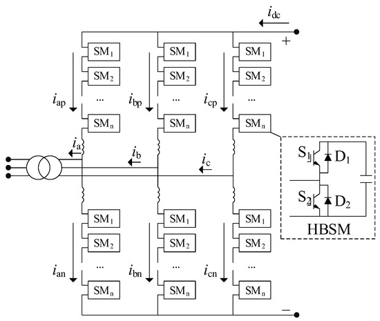
Figure 1.
Topology of MMC.
During normal MMC operation, submodule capacitor voltages fluctuate over time. However, as this paper focuses on the impact of the modulation link on DC voltage high-frequency harmonics (with capacitor voltages mainly affecting low-frequency components), it is assumed that all capacitor voltages equal their rated value UCN, i.e., uAcap_p(t) = uAcap_n(t) = UCN. Equation (1) can then be rewritten as follows:
If the valve-level controller ensures that the sum of inserted submodules in the upper and lower arms remains constant at all times (usually equal to the total number of arm submodules), according to Equation (2), no high-frequency harmonics will appear in the DC port voltage. However, control errors in the valve-level controller that cause fluctuations in the sum of inserted submodules may induce high-frequency harmonics in the DC port voltage. Taking the VSC-HVDC inverter side control method as an example, the control strategy is shown in Figure 2.
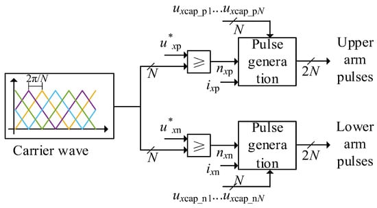
Figure 2.
Principle of valve control based on CPS modulation.
Figure 2 illustrates the basic principle of CPS modulation with four submodules, where N is the number of arm submodules, and are the reference voltages for the upper and lower arms of phase x, ixp and ixn are the arm currents, nxp and nxn are the number of inserted submodules in the upper and lower arms, and uxcap_p1…uxcap_pN and uxcap_n1…uxcap_nN are the capacitor voltages of the upper and lower arm submodules, respectively. The different colors are the different carrier wave. Triangular waves equal in number to the arm submodules are generated as carriers, with a phase shift of 2π/N between adjacent carriers. The upper and lower arm voltage reference waves are compared with the carriers, and the number of modulation waves exceeding the carriers determines the number of submodules to be inserted in each arm. Control pulses for switching devices are then calculated based on the number of inserted submodules, arm current direction, and capacitor voltage sorting.
The ideal CPS modulation process and results are shown in Figure 3. Using CPS modulation, the upper and lower arms of the MMC output stepped Pulse Width Modulation (PWM) waves. Notably, under ideal CPS modulation, the number of inserted and bypassed submodules in the upper and lower arms are complementary—i.e., the sum of inserted submodules in the upper and lower arms always equals the number of arm submodules (four in this case). This phenomenon is explained in Figure 4, where Am is the maximum carrier amplitude: the upper and lower arm submodules (2N in total) can be viewed as N submodule pairs. For each pair, the carriers and modulation waves of the upper and lower arms are symmetric about Am/2 (Figure 4a,c), ensuring that bypassing a submodule in the upper arm coincides with inserting a submodule in the lower arm, and vice versa. Thus, only one submodule in each pair is inserted at any time, and the total number of inserted submodules in the upper and lower arms remains N. According to Equation (2), ideal CPS modulation does not generate high-frequency harmonics on the DC side.
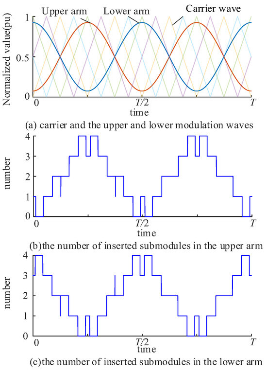
Figure 3.
Ideal waveforms based on CPS modulation.
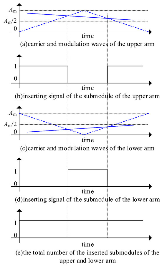
Figure 4.
Diagram of complementary switching and bypassing for upper and lower arm submodule pairs under ideal triangular wave conditions.
2.2. High-Frequency Harmonics Caused by Discretization of Triangular Carriers
In practice, MMC valve-level controllers are typically implemented using discrete devices such as Field Programmable Gate Arrays (FPGAs), which approximate continuous triangular waves with discrete step waves.
As shown in Figure 5, the discrete step wave is lower than the ideal triangular wave, causing the actual bypass time of submodules to lag behind the ideal case and the actual insertion time to precede the ideal case. This “early insertion and delayed bypass” error leads to simultaneous insertion of both submodules in a pair at certain moments (with the duration equal to one step time of the triangular wave). Considering there are a number of submodules per arm, this “early insertion and delayed bypass” will cause the total number of submodules inserted in the upper and lower arms to be greater than the ideal value at some time points, thereby introducing high-frequency harmonics into the DC voltage, as shown in Figure 5b,d,e.
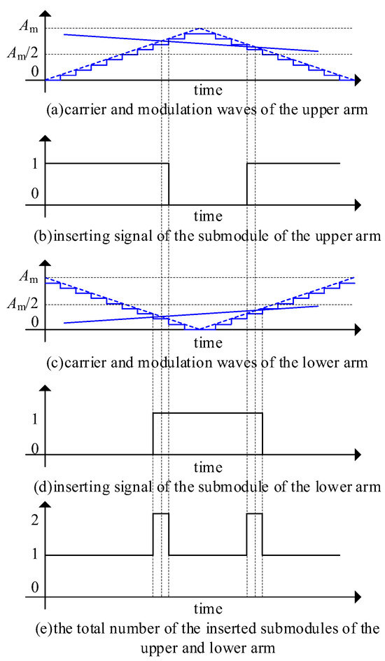
Figure 5.
Diagram to show the effects of discrete triangles on submodule pairs in upper and lower arm.
3. Discrete Carrier Compensation Method Based on Amplitude Symmetry
Taking Figure 5 as an example, the ideal triangular wave has a range of 0 to Am, with the sum of upper and lower arm carrier values always equal to Am at any time. However, the discrete triangular waves for the upper and lower arms have a range of 0 to Am − 1 due to quantization, making their sum Am − 1 instead of being exactly complementary about Am/2. This results in asynchronous insertion/bypass of submodule pairs.
To address this, a discrete carrier compensation method based on amplitude symmetry is proposed, as shown in Figure 6. By adding a compensation level to the lower arm carrier, the upper and lower arm triangular waves become exactly complementary about Am/2. As shown in Figure 7c, compensating the lower arm carrier with “+1” delays submodule insertion and advances submodule bypass in the lower arm, ensuring simultaneous insertion/bypass of upper and lower arm submodules. Although there is still a slight timing error compared to the ideal triangular wave, this error does not induce DC harmonics, and the proposed method has no significant impact on AC harmonics—a conclusion verified by the simulation results in this paper.
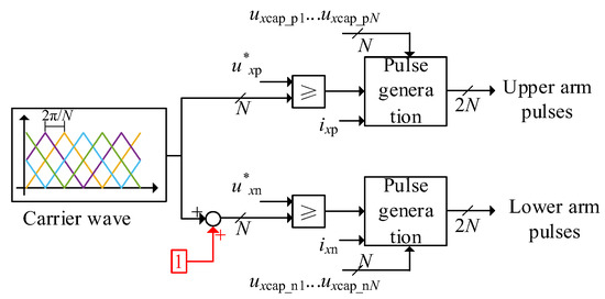
Figure 6.
Diagram of the discrete carrier compensation strategy proposed in this paper.
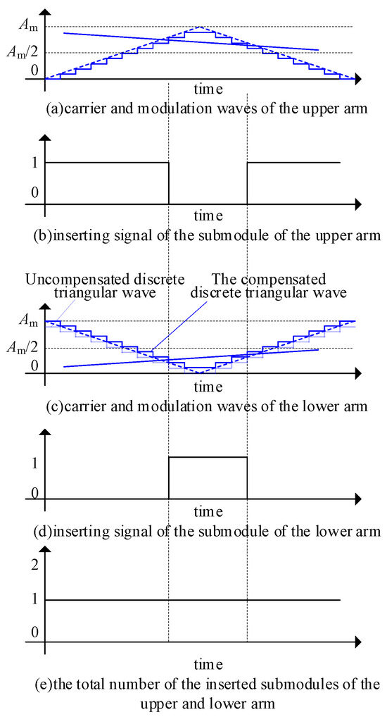
Figure 7.
Diagram of the effect of the proposed discrete carrier compensation strategy.
4. Case Study
A CPS-modulated MMC is used to analyze the impact of triangular wave quantization errors on DC voltage harmonics, with parameters listed in Table 1. The MMC has a rated DC voltage of 6.8 kV, a rated AC voltage (valve side of the converter transformer, line-to-line RMS) of 3.5 kV, a modulation ratio of 0.85 under no-load conditions, a submodule rated voltage of 1.7 kV, four submodules per arm (without redundancy), a carrier frequency of 1000 Hz, and 128 steps for the discrete triangular wave.

Table 1.
System parameters of the LCC-HVDC and VSC-HVDC.
The influence of triangular wave quantization errors on DC voltage harmonics is shown in Figure 8. Ideally, the sum of inserted submodules in the upper and lower arms should be four. However, as shown in Figure 8a, quantization errors cause the sum to reach five frequently in the DC port voltage of phase A. Figure 8b presents the FFT spectrum of the phase A DC port voltage over a 2 s period, revealing that quantization errors introduce harmonics in the DC voltage across a frequency range of several kilohertz to hundreds of kilohertz, with a Total Harmonic Distortion (THD) of 6%. Based on the observation result of Figure 8b, the identified harmonic frequencies have a relatively wide band, but exhibit no characteristic patterns. The harmonics generated by the discretization of the triangular carriers may be one of the sources of the high-frequency oscillations.
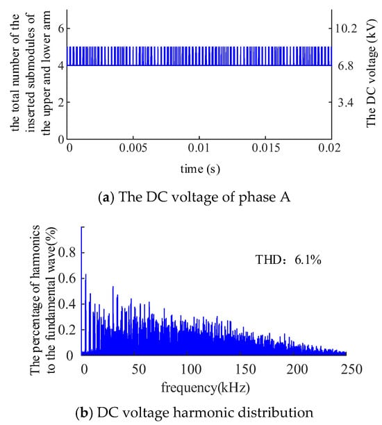
Figure 8.
Influence of quantitative error on DC voltage harmonics.
Based on this case, by adopting the discrete carrier compensation method proposed in this paper, the DC port voltage of the MMC can be obtained, as shown in Figure 9. Adopting the discrete carrier compensation method proposed in this paper can make the insertion and bypass of submodules in the upper and lower arms occur simultaneously, thus ensuring that the sum of the number of inserted submodules in the upper and lower arms is always equal to the number of arm submodules, and eliminating the DC high-frequency harmonics caused by carrier quantization errors.
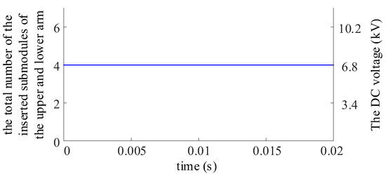
Figure 9.
Effect of proposed discrete carrier compensation.
5. Simulation Verification
A CPS-modulated MMC simulation model was built in Matlab/Simulink (R2021b) to validate the impact of carrier quantization errors on DC high-frequency harmonics and the effectiveness of the proposed discrete carrier compensation method. In the simulation model, each triangular carrier is discretized with 127 levels, thereby simulating the discrete effect in the FPGA. The modulation waves are compared with the carriers, thus generating the quantities of the submodules to be inserted. With the sorting results of the capacitor voltages, the switch signals are generated and drive the capacitors to be inserted and bypassed. Although the simulation is not as accurate as the hardware-based experiments, the detailed mathematical model considering the insertion and bypass of the submodules can still validate the correctness and effectiveness of the proposed theory. The simulation parameters match those in Table 1, and the simulation is conducted under no-load conditions to isolate the effect of carrier quantization errors from capacitor voltage fluctuations.
Simulation results using conventional CPS modulation are shown in Figure 10. Figure 10a depicts the phase A DC port voltage, where carrier quantization errors cause “early insertion and delayed bypass”, leading to frequent instances of five inserted submodules and significant high-frequency harmonics. FFT analysis of Figure 10a yields a THD of 6.05%, consistent with theoretical analysis. Figure 10b shows the MMC DC port voltage, where harmonics are partially canceled among phases but remain evident, with a THD of 3.4%. The AC port voltage in Figure 10c has a THD of 12.14% under this modulation strategy. Figure 10d presents the FFT analysis results of the AC port voltage, indicating that the harmonics are clustered around 4 kHz.
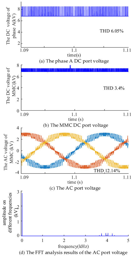
Figure 10.
Simulation results of DC and AC voltages based on the conventional CPS modulation strategy.
The results using the proposed discrete carrier compensation method are shown in Figure 11. Figure 11a,b demonstrates that the method eliminates DC high-frequency harmonics caused by carrier quantization errors in both phase A and the total MMC DC port voltage. The AC port voltage in Figure 11c has a THD of 12.06%, where different colors lines represent the three-phase voltage, showing no significant increase in AC harmonics compared to conventional CPS modulation. Figure 11d also presents the FFT analysis result. By comparing Figure 10d and Figure 11d, it is concluded that the harmonic distributions of the AC voltage are similar, indicating that the proposed method does not affect the AC voltage to a large extent.
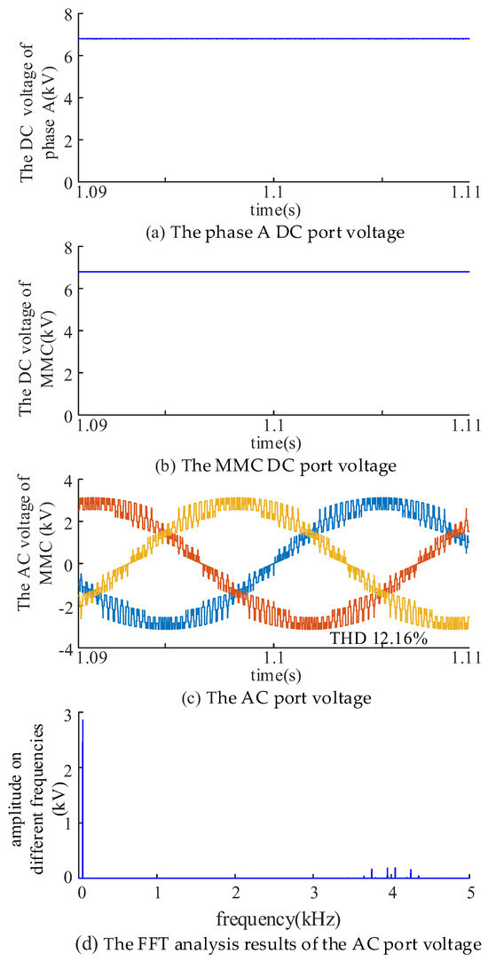
Figure 11.
Simulation results of DC and AC voltages based on the CPS modulation strategy with discrete carrier compensation.
6. Conclusions
This paper analyzes the impact of MMC valve-level controller modulation on DC high-frequency harmonics, revealing that carrier discretization-induced quantization errors cause “early insertion and delayed bypass” of upper/lower arm submodules, leading to DC voltage high-frequency harmonics. A discrete carrier compensation method based on amplitude symmetry is proposed by simply adding one to the carriers of the lower arm, thereby eliminating the harmonics caused by carrier quantization errors, while other controllers remain unchanged. The case study results show that quantization errors introduce DC voltage harmonics across a frequency range of several kilohertz to hundreds of kilohertz. The simulation results validate the proposed harmonic generation mechanism and the effectiveness of the discrete carrier compensation method. The simulation results also verify that the proposed discrete carrier compensation method will not affect the AC harmonics. The research conclusions of this paper can provide a new idea for analyzing the high-frequency harmonics and oscillations on the DC side.
Author Contributions
Conceptualization, Q.H.; methodology, Y.J.; validation, X.X.; supervision, Z.J.; project administration, X.Y.; funding acquisition, M.Y. All authors have read and agreed to the published version of the manuscript.
Funding
This research was funded by the State Grid Jibei Electric Power Co., Ltd. science and technology project (52018K230008).
Data Availability Statement
The original contributions presented in the study are included in the article, further inquiries can be directed to the corresponding author.
Conflicts of Interest
Authors Qing Huai, Yirun Ji, Ziyao Jie and Xi Yuan were employed by the company Electric Power Research Institute of State Grid Jibei Electric Power Co., Ltd. Author Minxiang Yang was employed by the company State Grid Jibei Electric Power Co., Ltd. The authors declare that this study received funding from the State Grid Jibei Electric Power Co., Ltd. The funder was not involved in the study design, collection, analysis, interpretation of data, the writing of this article or the decision to submit it for publication. The remaining authors declare that the research was conducted in the absence of any commercial or financial relationships that could be construed as a potential conflict of interest.
References
- Shu, Y.; Zhao, Y.; Zhao, L.; Qiu, B.; Liu, M.; Yang, Y. Study on low carbon energy transition path toward carbon peak and carbon neutrality. Proc. CSEE 2023, 43, 1663–1672. [Google Scholar]
- Kouro, S.; Malinowski, M.; Gopakumar, K.; Pou, J.; Franquelo, L.G.; Wu, B.; Rodriguez, J.; Pérez, M.A.; Leon, J.I. Recent Advances and Industrial Applications of Multilevel Converters. IEEE Trans. Ind. Electron. 2010, 57, 2553–2580. [Google Scholar] [CrossRef]
- Debnath, S.; Qin, J.; Bahrani, B.; Saeedifard, M.; Barbosa, P. Operation, Control, and Applications of the Modular Multilevel Converter: A Review. IEEE Trans. Power Electron. 2015, 30, 37–53. [Google Scholar] [CrossRef]
- Pang, H.; Wei, X. Research on Key Technology and Equipment for Zhangbei 500kV DC Grid. In Proceedings of the 2018 International Power Electronics Conference (IPEC-Niigata 2018-ECCE Asia), Niigata, Japan, 20–24 May 2018; pp. 2343–2351. [Google Scholar]
- Li, J.; Zhu, B.; Guo, Y.; Liang, Z.; Wu, H.; Liu, H. The Simulation of Kunliulong Flexible DC Project with Single Station Operation and out of Operation. In Proceedings of the 2021 IEEE/IAS Industrial and Commercial Power System Asia (I&CPS Asia), Chengdu, China, 18–21 July 2021; pp. 1028–1034. [Google Scholar]
- Huifan, X.; Yang, S.; Guanghu, X.; Tao, L.; Weihuang, H.; Xuehua, L.; Yangzheng, W. Abnormal Analysis and Optimization Measures of Valve-controlled Trigger of Kunliulong Hybrid Multi-terminal UHVDC Project. In Proceedings of the 2023 8th Asia Conference on Power and Electrical Engineering (ACPEE), Tianjin, China, 14–16 April 2023; pp. 1551–1556. [Google Scholar]
- Saad, H.; Fillion, Y.; Deschanvres, S.; Vernay, Y.; Dennetière, S. On Resonances and Harmonics in HVDC-MMC Station Connected to AC Grid. IEEE Trans. Power Deliv. 2017, 32, 1565–1573. [Google Scholar] [CrossRef]
- Li, Y.; Pang, H.; Kong, M.; Lu, J.; Ji, K.; Tang, G. Compensation control and parameters design for high-frequency resonance suppression of MMC-HVDC system. CSEE J. Power Energy Syst. 2021, 7, 1161–1175. [Google Scholar]
- Wu, H.; Wang, X.; Kocewiak, Ł.; Harnefors, L. AC Impedance Modeling of Modular Multilevel Converters and Two-Level Voltage-Source Converters: Similarities and Differences. In Proceedings of the 2018 IEEE 19th Workshop on Control and Modeling for Power Electronics (COMPEL), Padua, Italy, 25–28 June 2018; pp. 1–8. [Google Scholar]
- Yue, B.; Lyu, J.; Yin, J.; Yuan, B.; Li, X.; Yu, H.; Yin, C.; Wang, B. Review of suppression strategies for high-frequency oscillations in MMC-HVDC systems. In Proceedings of the 10th Renewable Power Generation Conference (RPG 2021), Online Conference, 14–15 October 2021; pp. 1015–1019. [Google Scholar]
- Wen, B.; Boroyevich, D.; Burgos, R.; Mattavelli, P.; Shen, Z. Small-Signal Stability Analysis of Three-Phase AC Systems in the Presence of Constant Power Loads Based on Measured d-q Frame Impedances. IEEE Trans. Power Electron. 2015, 30, 5952–5963. [Google Scholar] [CrossRef]
- Canay, I.M. A Novel Approach to the Torsional Interaction and Electrical Damping of the Synchronous Machine. Part I: Theory. IEEE Power Eng. Rev. 1982, 10, 24. [Google Scholar] [CrossRef]
- Yuan, H.; Yuan, X.; Hu, J. Modeling of Grid-Connected VSCs for Power System Small-Signal Stability Analysis in DC-Link Voltage Control Timescale. IEEE Trans. Power Syst. 2017, 32, 3981–3991. [Google Scholar] [CrossRef]
- Li, Y.; An, T.; Zhang, D.; Pei, X.; Ji, K.; Tang, G. Analysis and Suppression Control of High Frequency Resonance for MMC-HVDC System. IEEE Trans. Power Deliv. 2021, 36, 3867–3881. [Google Scholar] [CrossRef]
- Hao, Q.; Li, Z.; Gao, F.; Zhang, J. Reduced-Order Small-Signal Models of Modular Multilevel Converter and MMC-Based HVdc Grid. IEEE Trans. Ind. Electron. 2019, 66, 2257–2268. [Google Scholar] [CrossRef]
Disclaimer/Publisher’s Note: The statements, opinions and data contained in all publications are solely those of the individual author(s) and contributor(s) and not of MDPI and/or the editor(s). MDPI and/or the editor(s) disclaim responsibility for any injury to people or property resulting from any ideas, methods, instructions or products referred to in the content. |
© 2025 by the authors. Licensee MDPI, Basel, Switzerland. This article is an open access article distributed under the terms and conditions of the Creative Commons Attribution (CC BY) license (https://creativecommons.org/licenses/by/4.0/).