Article

Reactive Power Compensation for Single-Phase AC Motors Using Integral Power Theory

Department of Electrical Machines, Drives and Measurements, Faculty of Electrical Engineering, Wroclaw University of Science and Technology, 50-372 Wroclaw, Poland
*
Author to whom correspondence should be addressed.
Energies 2025, 18(10), 2641; https://doi.org/10.3390/en18102641
Submission received: 10 April 2025 / Revised: 9 May 2025 / Accepted: 12 May 2025 / Published: 20 May 2025
(This article belongs to the Special Issue Energy, Electrical and Power Engineering: 4th Edition)

Abstract

:
The paper investigates an alternative approach to measuring and compensating reactive power in electric machines, particularly under non-sinusoidal voltage and current waveforms. Traditional power definitions, such as those introduced by Budeanu and Fryze, as well as the power triangle, are discussed alongside integral definitions of reactive power, which account for waveform distortions. This approach is novel and has not been previously applied in the context of electric machines. A digital algorithm for reactive power calculation, based on the integral definition, is proposed. It requires minimal computational resources and is easy to implement. Experimental measurements conducted on a single-phase induction motor demonstrate the impact of capacitive compensation on current waveforms. The results confirm the validity of the adopted definition of reactive power. With full reactive power compensation, the RMS value of the current drawn by the motor is minimized, which is not always the case with the classical approach to improving the power factor. The findings highlight the importance of accurate reactive power measurement and compensation in enhancing the performance and energy efficiency of electrical machines. The proposed approach is applicable not only to single-phase motors but also more broadly in determining the reactive power drawn by electric machines and in measuring electric energy, particularly in the presence of distorted voltages and currents.

1. Introduction

In a steady state, the power delivered to an object under a direct current (DC) voltage, when the current does not change over time, is entirely converted into work and heat. Alternating current (AC) power does not possess this property. Under an applied AC voltage, even a large alternating current may flow, while the work performed and heat dissipated may be close to zero.
The average electrical energy over a voltage as well as current waveform period, known as active power, is converted into work and heat.
P = 1 T t k T + t k p d t = 1 T t k T + t k u i d t ,
where p = u∙i—instantaneous electrical power; u, i—voltage and current periodically varying with period T, tk—any instant.
If a sinusoidal voltage is applied to the object,
u = U m sin ( ω t ) ,
which causes a sinusoidal current drawn by the object
i = I m sin ( ω t ϕ ) ,
where Um—voltage amplitude, Im—current amplitude, and ω—angular frequency.
The object is linear and can be replaced by an electrical circuit with constant parameters R, L, and C (Figure 1). In Equation (3), ϕ is the phase angle between voltage and current.
The active power drawn by a linear object powered by a sinusoidal voltage is
P = U I cos ϕ = S cos ϕ ,
where U and I are the RMS values of voltage and current, and S is the apparent power.
Active power can also be determined using the resistance R of the equivalent circuit.
P = U 2 R .
The resistance R models the phenomenon of converting electrical power into work and heat.
Reactive power
Q = U I sin ϕ ,
is defined such that
P 2 + Q 2 = S 2 .
Powers P, Q, and S in the case of sinusoidal current and voltage waveforms form the so-called power triangle (7). Reactive power depends on the parameters L and C of the equivalent circuit, modeling the occurrence of electrical energy in the form of an electric field and a magnetic field.
Q = U 2 ω C 1 ω L ,
At a given angular frequency ω, the object’s parameters can be chosen such that Q = 0 (the so-called reactive power compensation occurs). Reactive power compensation is desirable because it minimizes the current drawn from the power supply by the load, while keeping the active power unchanged.
Reactive power, defined by relation (8), similarly to active power, is a quantity that can be balanced in a circuit (is an additive quantity).
For non-sinusoidal current and voltage waveforms, there is no unambiguous definition of reactive power. Equation (7) is not satisfied.
Over the years, many theories and methods of measuring reactive power have emerged. It can be observed that the two definitions of reactive power dominate, on which many other, more complex theories of reactive power are based.
The first—the most widespread and practically used—is the method of calculating reactive power given in 1927 by C. Budeanu [1]. The definition of reactive power was constructed analogously to the formula describing active power in the frequency domain. To close the power triangle, a new quantity was added—distortion power D, which is attributed to being a measure of current distortion with respect to voltage.
S 2 = P 2 + Q 2 + D 2 ,
The idea behind the second significant power theory, proposed by S. Fryze, is to decompose the current into an active component (carrying active energy) and a reactive component orthogonal to the active current component [2].
The approach to describing the energy state of a circuit initiated by S. Fryze, which involves decomposing the current into mutually perpendicular components to which phenomena in the circuit are attributed, is continued in later works by, among others, W. Shepherd and P. Zakikhani [3], N.L. Kusters and W.J.M. Moore [4], and L. Czarnecki [5,6,7].
The article [8] presents research on the selection of a passive compensator, L, C, or LC. The selection of the compensator is based on the Budeanu theory [1] and the theory of the physical components of current (CPC) [6,7]. The article [9] also deals with passive compensation and the use of the Budeanu and CPC theories, which were applied in 3-Phase 4-Wire Systems.
An attempt to unify and systematize the method of defining and measuring reactive power can be found in the IEEE 1459-2010 standard [10]. This standard is an attempt to unify and systematize the method of defining and measuring reactive power—dedicated to engineering applications.
This standard does not facilitate the implementation of simple, practical solutions. In the introduction to the standard [10], it is emphasized that there is still no power theory that could be simultaneously applied to the following:
  • reactive energy billing [11,12,13],
  • power quality assessment,
  • the detection of main waveform distortion sources, and
  • theoretical calculations for the design of active filters and compensators.
The IEEE 1459 standard [10] aims to provide extended definitions based on well-established power theories. The standard is not helpful in designing real-time control for dynamic compensators, and the definitions presented in it are intended to serve as guidelines and a useful reference point for future developments.
The monitoring of power quality is a crucial factor in modern electrical environments and power grids. Poor power quality affects the normal operation of electric motors and drives, leading to malfunctions or, in the worst cases, irreparable damage. Additionally, the regular operation of motors and drives introduces power disturbances into the grid, such as voltage sags and flickers during start-up, as well as harmonic and interharmonic content generated by variable-frequency drives [13]. Peplinski and Gnaciński et al. studied induction motors, both single-phase [14] and three-phase [15], supplied with voltages containing subharmonics and interharmonics, resulting from voltage fluctuations. They found that these fluctuations cause high-velocity vibrations and that torque pulsations caused by harmonics and interharmonics combine algebraically. Elphick and Crawford et al. [16] analyzed the impact of voltage magnitude, harmonic distortion, and voltage unbalance on the operation of both single-phase and three-phase induction motors. Hasan and Parida [17] examined a single-phase motor powered by a variable-frequency drive, finding that under these conditions, the motor behaves similarly to a machine with faulty bearings and broken rotor bars. Donolo and Pezzani et al. [18] investigated the effect of voltage unbalance on losses in induction motors across different efficiency classes. Their findings indicate that the losses caused by poor power quality are greater in high-efficiency machines. Cogburn and Bhattarai [19] studies the impact of unbalanced supply conditions on the performance and efficiency of induction motors, highlighting the losses resulting from negative-sequence currents. The authors proposed a novel compensation method based on the current’s physical components power theory. The technique effectively reduces negative-sequence currents; however, only the simulation results are presented. Oliveira and Soares et al. [20] designed a back-to-back converter for an induction drive, intended to provide power factor correction, harmonic compensation, and resilience to voltage sags, in addition to its standard function, i.e., speed and torque control. There are relatively few studies concerning reactive power compensation in the context of single-phase induction motors. There are papers that address compensation in single-phase systems more generally. Guo and Zhong et al. [21] proposed a novel control algorithm for a single-phase static compensator, based on precise reactive current tracking, utilizing a PI controller and a novel system dynamics estimator for disturbance estimation. Simulation results are presented to validate the theoretical claims. Binkowski and Nowak et al. [22] presented a system designed to transfer PV-generated power to a single-phase power grid while also providing reactive power compensation. The method was applied to an isolated 400 Hz, single-phase power grid. These selected studies highlight the significant impact of power quality on motor performance and reliability. Understanding and mitigating voltage fluctuations, harmonics, and other disturbances are essential for ensuring the efficient and safe operation of electrical machines.
Active power measurements are definitionally unambiguous, whereas the correct determination of reactive power values presents a problem. This is a definitional issue, and the power triangle definition (7) is most frequently used; however, it does not yield good results with non-sinusoidal current and voltage waveforms. This applies not only to electrical machines but also to reactive energy measurements [11,12]. This paper aims to highlight the measurement problems that occur when determining reactive power for distorted waveforms. A change in approach to determining this power using the integral definition for non-sinusoidal signals seems purposeful, as it yields a measurable effect in the form of minimizing the RMS current consumed by electrical machines.

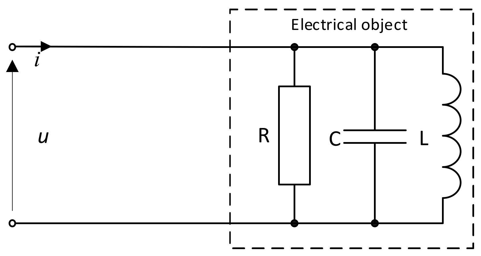
2. Integral Definitions of Reactive Power

The integral determination of reactive power has been known for over 100 years. M. Iliovici [23] provides two definitions of reactive power based on the scalar product of current or voltage and quantities that are linearly dependent on current and voltage.
Q i = ω T 0 T q u d t = ω T 0 T ψ i d t ,
Q d = 1 ω T 0 T u d i d t d t = 1 ω T 0 T i d u d t d t
where ψ = u d t ; q = i d t ; ω—angular frequency.
The quantity ψ has the dimension of magnetic flux, while q has the dimension of electric charge. Both Formulas (10) and (11) give the same value of power when one of the waveforms (voltage or current) is sinusoidal. To distinguish the reactive power where, depending on where it occurs, there is a substitute magnetic flux or a substitute electric charge, it is denoted by the symbol Qi, while the powers where there is a derivative of current or voltage are denoted by the symbol Qd. If both waveforms are non-sinusoidal, the values of powers Qd and Qi are different. This same method of measuring reactive power is also found in the IEEE standard [10]. For any periodic current and voltage waveforms, the reactive powers defined by Formulas (10) and (11) have a geometric interpretation in the absence of a DC component [24,25,26,27]. The Qi power is proportional to the loop area in the q, ψ coordinates (12), while the Qd power is proportional to the loop area in the u, i coordinates (13).
Q i = ω T ψ d q = ω T q d ψ ,
Q d = 1 2 π u d i = 1 2 π i d u .
For sinusoidal current and voltage waveforms, the loops are ellipses. If the reactive power is equal to zero, the loops become a line segment.
Relations (10) and (11) in the frequency domain take the form of series
Q i = n = 1 1 n U n I n sin ϕ n = n = 1 1 n Q n ,
Q d = n = 1 n U n I n sin ϕ n = n = 1 n Q n .
The implementation of a digital algorithm for calculating reactive power using Formulas (10) to (13) does not require high processor computational power. Assuming that N samples fall within one period, the dependencies (1), (10), and (11) take the following form:
P = 1 N k = 0 N 1 u k · i k
where uk and ik represent the next voltage and current sample.
Q d = 1 ω 1 N k = 0 N 1 u k · d i k = 1 ω 1 N k = 0 N 1 i k · d u k
where duk and dik are the corresponding samples of the voltage and the current derivatives.
Q i = ω 1 N k = 0 N 1 i k · y k = ω 1 N k = 0 N 1 u k · q k
where ψk and qk are the corresponding samples of the equivalent magnetic flux and electric charge.

3. Minimization of the RMS Value of the Load Current or Voltage

One of the fundamental goals of knowing the reactive power value is to minimize currents flowing in the power system and to minimize the resulting power losses. Reactive powers Qd and Qi have different values for non-sinusoidal current and voltage waveforms. Also, in the general case, the power triangle (7) is not satisfied. This property is not necessary to minimize the RMS value of the current flowing through the load.
The instantaneous value of the current supplying an electrical object with a parallel equivalent circuit composed of linear elements (Figure 2) is
i = u R + 1 L r u d t + C r d u d t .
Hence, the square of the RMS current value
I 2 = 1 T 0 T i 2 d t = C r 2 U ˙ 2 + 1 L r 2 Ψ 2 2 C r L r U 2 + 1 R 2 U 2 .
Minimizing the RMS value of the current involves connecting a capacitor or an inductor in parallel with the object. Single-element passive compensators do not provide current minimization like active compensators. However, economic considerations and low failure rates are the reasons for their wide use in various areas.
Figure 2. Compensation with a parallel single-element compensator.
Energies 18 02641 g002

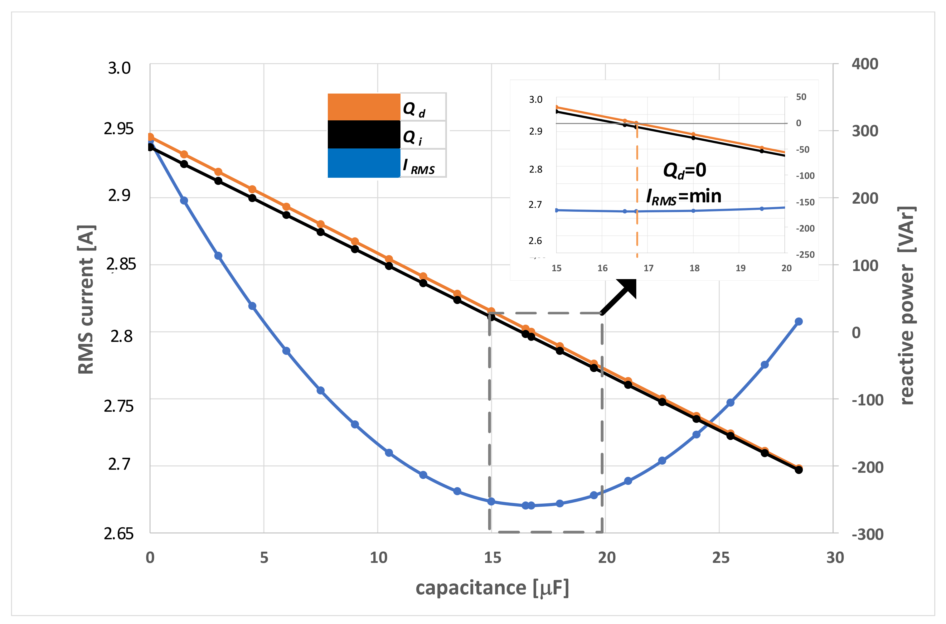
3.1. Minimization of the RMS Current Value with a Parallel-Connected Capacitor

The RMS current in the circuit will be minimal after connecting a capacitor Ck in parallel when
d d C I 2 = 2 C U ˙ 2 1 L r U 2 = 0 ,
where C is the sum of the object’s capacitance Cr and the compensator’s capacitance Ck. The expression in parentheses corresponds to the reactive power Qd calculated from the loop area in the u, i coordinates (or from relations (11) and (15)) of the object with the connected compensator (Figure 2). The minimum RMS current occurs when C has a value that causes Qd to become zero, which is equivalent to the loop area being equal to zero. This situation occurs after connecting a capacitor with a value of
C k = ω Q d U ˙ 2 ,
where Q′d is the reactive power before connecting the capacitor (the power to be compensated).

3.2. Minimization of the RMS Current Value with a Parallel-Connected Inductor

The RMS current in the circuit will be minimal after connecting an inductor in parallel, when
d d L I 2 = 2 L 2 C U 2 1 L Ψ 2 = 0 ,
where L is the inductance of the parallel-connected inductances of the compensator Lk and the object’s inductance Lr.
1 L = 1 L k + 1 L r .
The expression in parentheses in Formula (23) corresponds to the reactive power Qi calculated from the loop area in the ψ, q coordinates. The minimum RMS current occurs after connecting a compensator Lk with an inductance value that causes the ψ, q loop area to become zero.
This situation occurs after connecting a compensator with a value of
L k = ω Ψ 2 Q i
where Q′i is the reactive power before connecting the inductor (to be compensated).
In the case of a capacitive object, the Qd power is negative, and an inductor with a value determined by Formula (25) should be added in parallel.

4. Results and Discussion

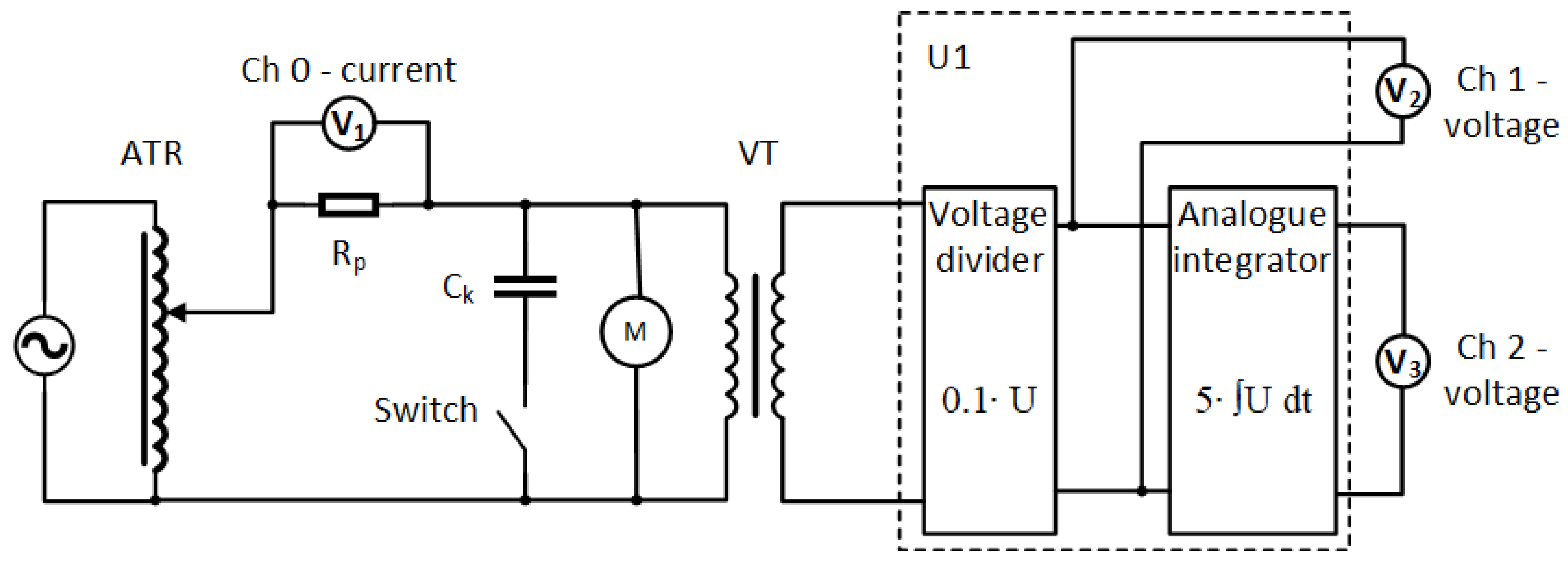
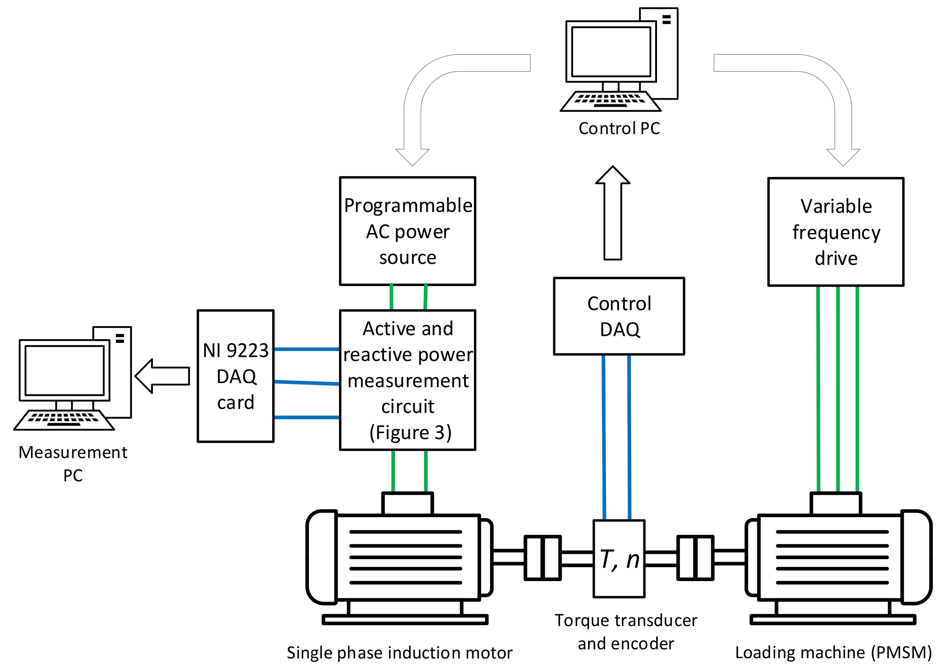
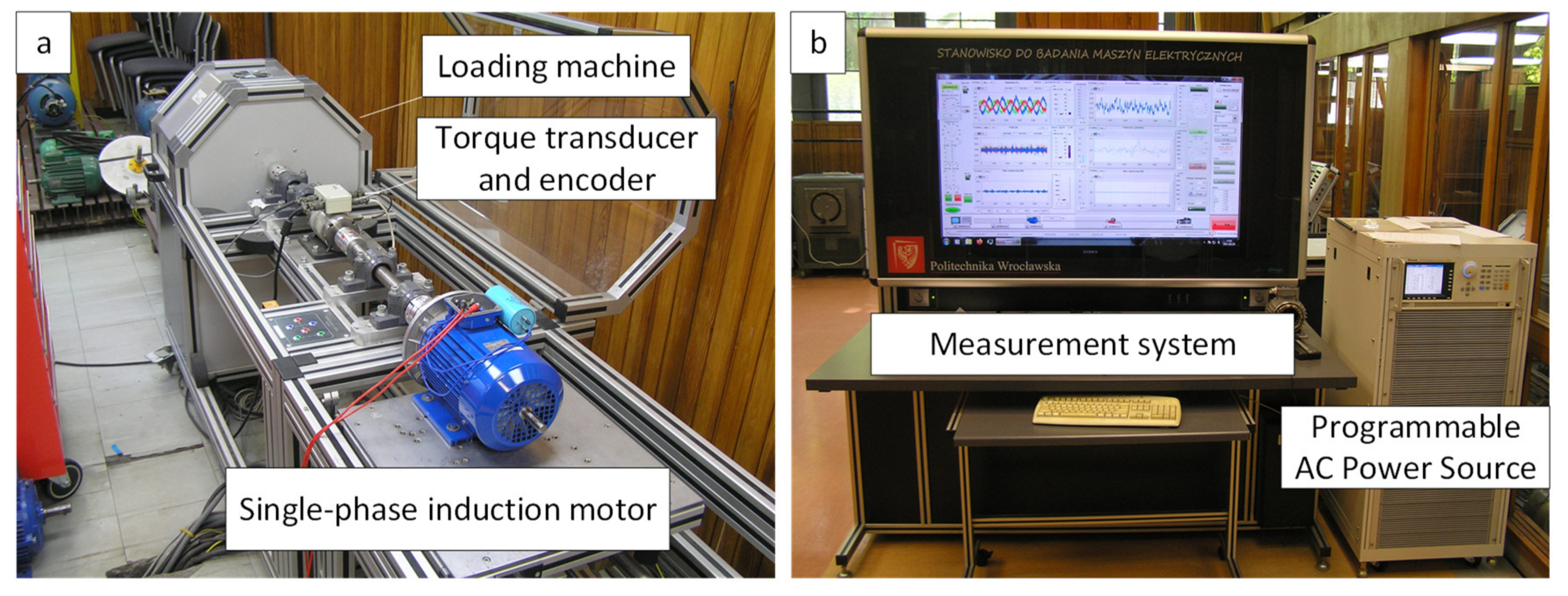
4.1. Description of the Research Object and Measurement Setups

The machine selected for this study is a single-phase, permanent-split capacitor induction motor, designed for continuous operation (S1 duty cycle). The motor’s ratings and parameters are listed in Table 1.
The active and reactive power measurements were conducted using the setup shown in Figure 3 according to the algorithm presented in Formulas (16)–(18). To ensure the accuracy of power measurements for any object, it is necessary to simultaneously sample current and voltage signals. To minimize phase shifts, a resistive shunt (class 0.2, Rp in Figure 3), a voltage transformer VT (class 0.2), and a voltage divider (class 0.1) were incorporated into the analog processing path. The synchronization of current and voltage samples is crucial for accurate power measurement, as the asynchronous sampling of measured signals can introduce errors, particularly under variable load conditions. To meet the set requirements, data acquisition was carried out using the NI 9223 simultaneous sampling (accuracy 0.02% of reading + 0.01% of range); this indicates that the DAQ board introduces no phase shifts between the channels because its architecture consists of parallel processing paths, ensuring correct acquisition. The DAQ card, operating at a sampling frequency of 10 kSps (200 samples per period is enough), is supported by a custom program written in the LabView environment. Voltmeters V1, V2, and V3 correspond to channels 0, 1, and 2 of the DAQ system. The capacitor C represents the compensation capacitance. To estimate active and reactive power, the voltages are fed into the DAQ card via an analog integrator and a voltage divider, respectively (block U1 in Figure 3).
Reactive power compensation was carried out under no-load conditions. The motor was supplied with the mains voltage through a variable autotransformer, as illustrated in Figure 3. Testing the motor under load conditions was conducted on a different test bench, with its functional diagram shown in Figure 4. The induction motor was powered by a programmable voltage source capable of supplying both sinusoidal and distorted voltage waveforms. The mechanical load was provided by the 7.1 kW MCS permanent magnet synchronous servo motor operating in braking mode, controlled by a variable-frequency drive. A photo of the mechanical part of the test bench, which consists of the single-phase motor, the torque transducer, and the loading machine, is shown in Figure 5.

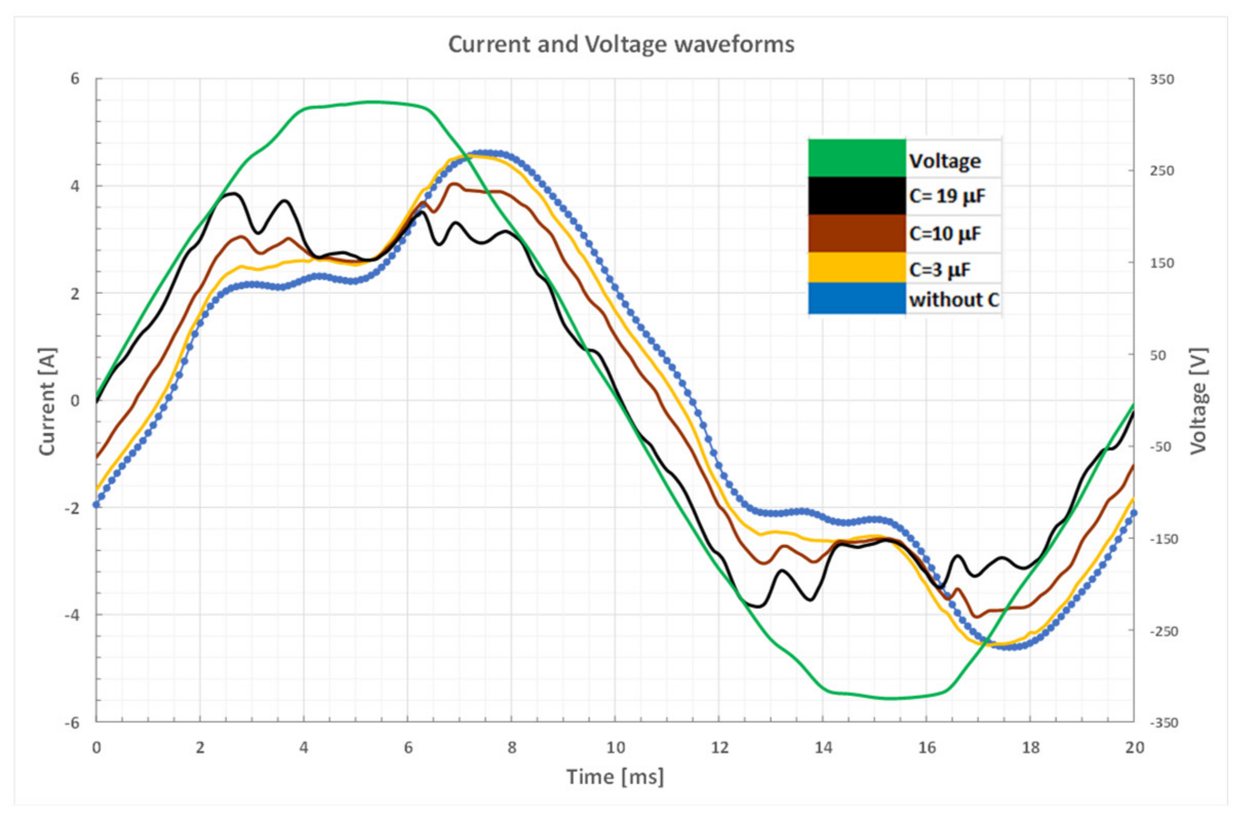
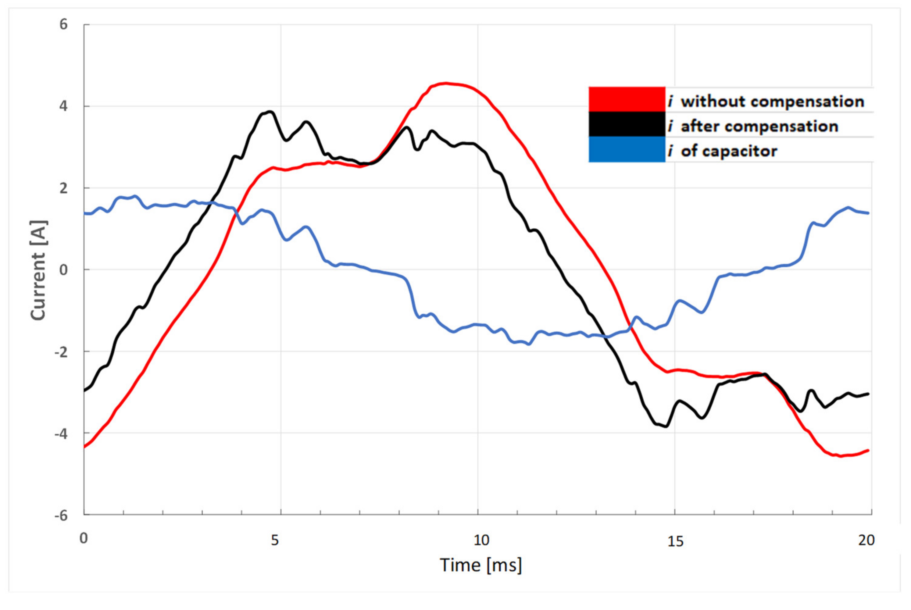
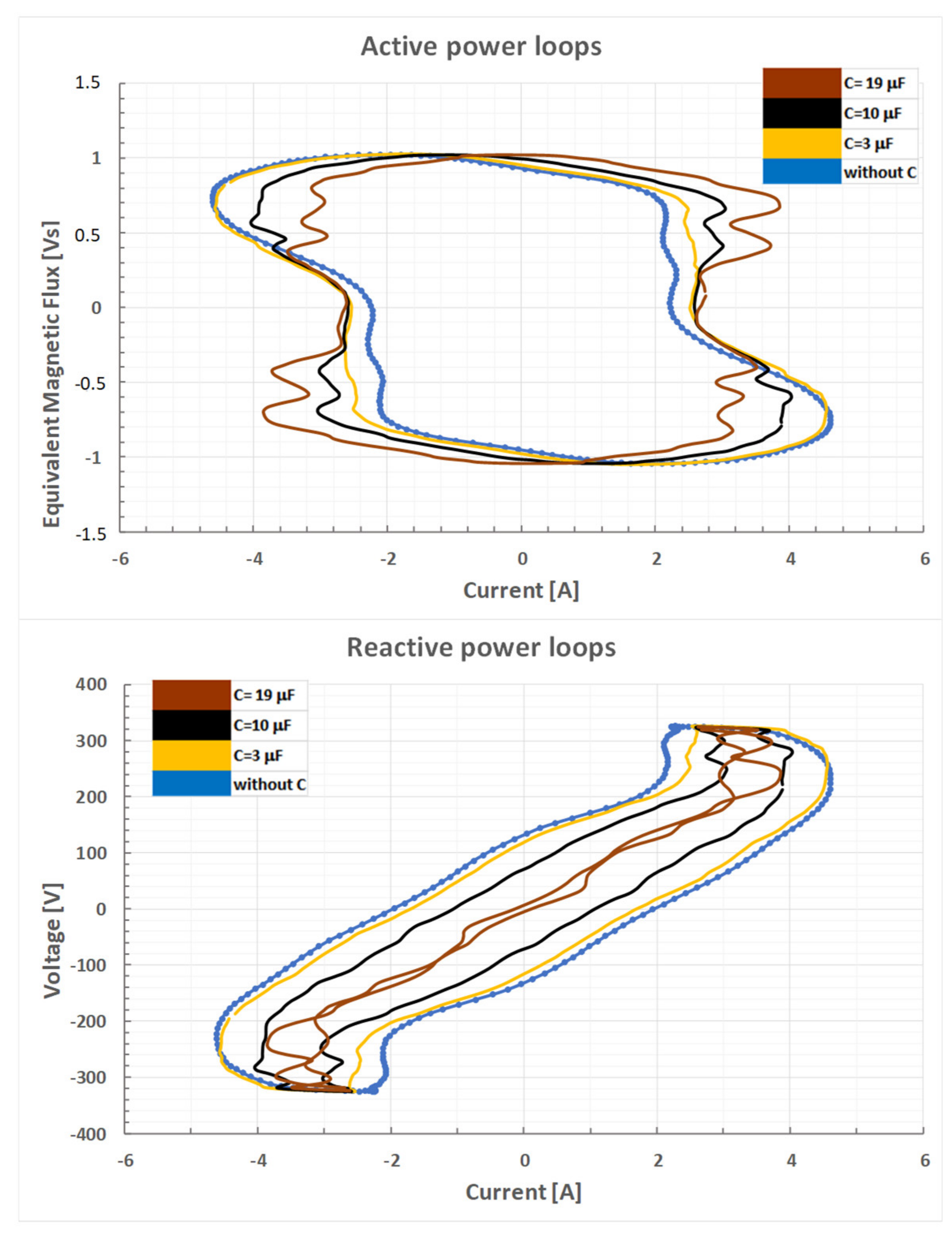
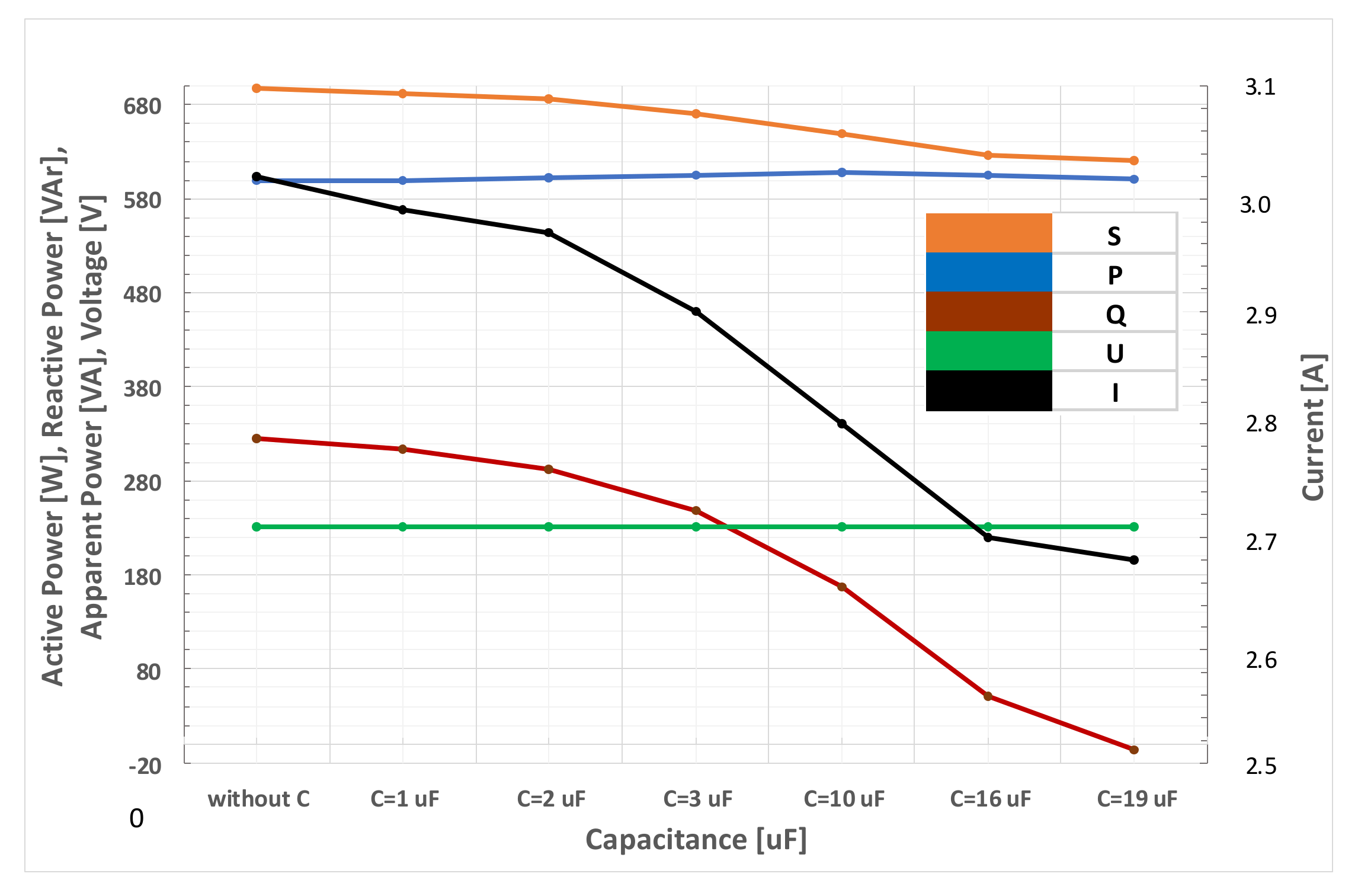
4.2. Reactive Power Compensation of the Load

In the power supply systems of electric motors, especially single-phase ones, reactive power is present, related to the inductance of the windings. Reactive power is not used to perform work but causes an additional load on the network and leads to energy losses in it. In order to minimize these adverse effects, reactive power compensation is applied by connecting capacitors. The current waveform in the circuit with a single-phase motor was measured with different values of the capacitor compensating reactive power, from 1 µF to 19 µF. Figure 6 shows the measured waveforms of the mains voltage with harmonic content THD = 4.6% (green color) and currents resulting from the connection of selected capacitors compensating reactive power to the measured object. The blue color corresponds to the system without compensation, while the yellow, brown, and black colors in Figure 6 correspond to the capacities of 3, 10, and 19 μF, respectively.
Changes in current distortion and the phase shift between current and voltage were recorded. The connection of capacitors compensating reactive power caused a distortion of the current waveform, characterized by the appearance of higher harmonics.
The phenomenon of current distortion is related to the connection of a capacitor, and the degree of current distortion increases with increasing capacitance (iC = C du/dt). The phase shift between current and voltage indicates that the measured object has an inductive character, which is confirmed by the reactive power Qd, which has a positive value.
Figure 7 shows the dependence of the rms value of the current drawn from the mains and reactive power on the value of the capacitor capacitance during the compensation of reactive power Qd. As can be seen, both the rms value of the current is the smallest and the power Qd is equal to zero for the capacitor capacitance of 16.6 μF.
The instantaneous values of the current before compensation (red), the current drawn from the mains after compensation (black), and the capacitor current (blue) are shown in Figure 8. The capacitor current is phase shifted relative to the current drawn by the motor (current before compensation). These currents are added together, limiting both the maximum and rms values of the current drawn from the mains.
The analysis of active and reactive power loops shown in Figure 9 reveals significant dependencies. Despite the observed changes in the shape and slope of the active power loops after connecting compensating capacitors, their area remains relatively constant. In contrast to the active power loops, the reactive power loops show significant changes in both shape and area. In the case of connecting a capacitance C = 19 μF, a slight overcompensation occurs, resulting in a change in the character of reactive power from inductive to capacitive.
The analysis of the characteristics shown in Figure 10 reveals the impact of reactive power compensation on the RMS values of the electrical parameters of an induction motor powered from the power grid. As the capacitance of the capacitor increases, a decrease in reactive power is observed, which is consistent with expectations. For the last point (C = 19 μF), overcompensation occurs. If a capacitor smaller by 400 nF were connected, the Qd power would be equal to zero, and the current drawn by the motor would be minimized.
In power networks where devices generating higher harmonics appear, the supply voltage is distorted. In such a situation, resonance can occur between the capacitor and the supply network inductance at a harmonic frequency. Protective reactance is used to protect capacitors. They form resonant circuits with the capacitor capacitances, protecting the capacitors from the influence of higher harmonics. The resonant frequency of the reactor and capacitor set should fall between the harmonics.

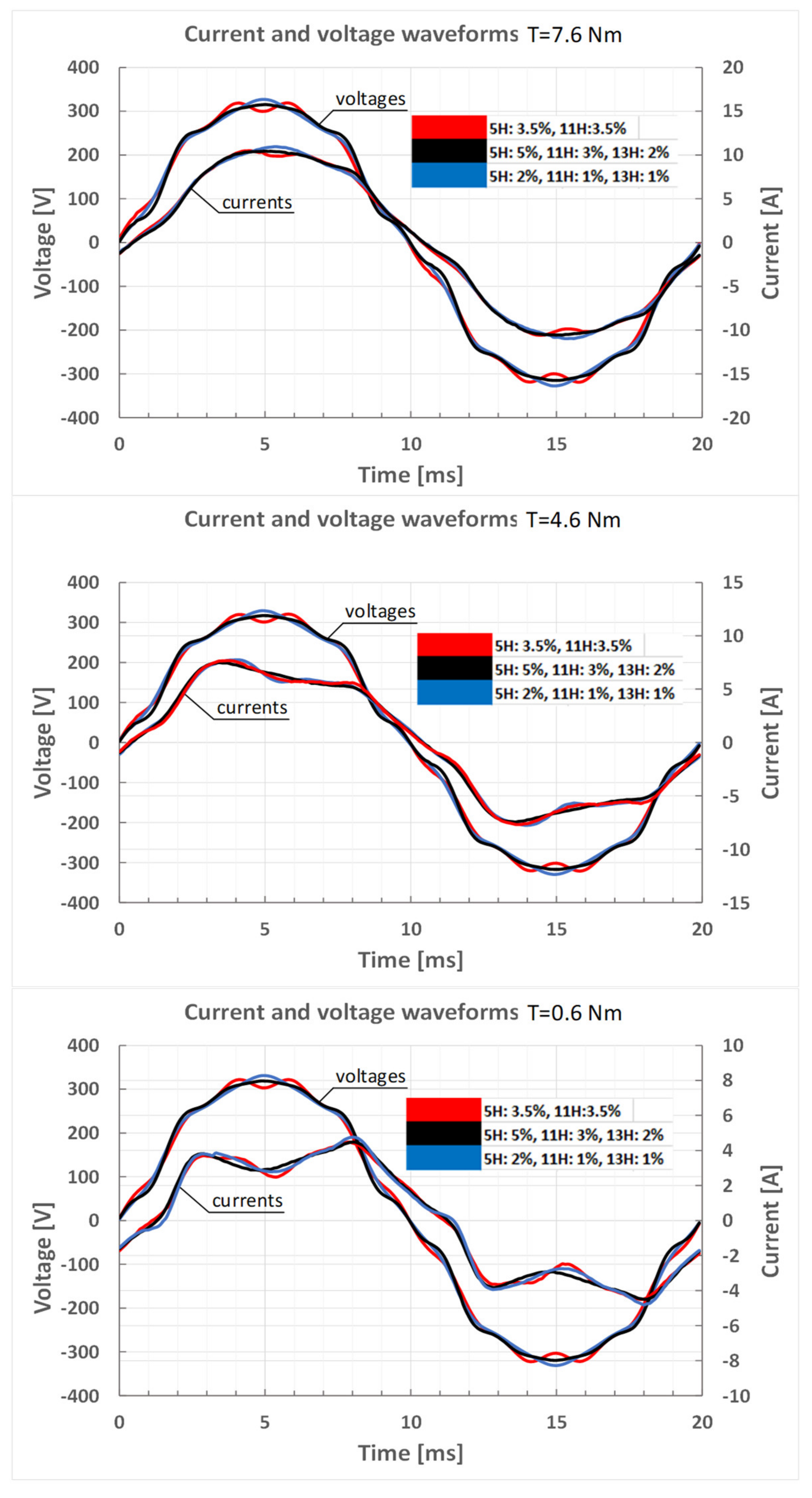
4.3. Effects of Distorted Voltage on Power Values

Figure 11 and Figure 12 show the effects of distorted supply voltage on the current waveforms and also on the shapes and areas of power loops at different load values. As can be seen in Figure 11, the deformation of the motor current from the sinusoidal waveform is more visible at a lower load torque.
The measured reactive power variations are attributed to the specific characteristics of the measured object, which is a single-phase induction motor. The analysis of an object powered by a voltage containing the fifth, eleventh, and thirteenth order harmonics revealed their influence on the shape of the active and reactive power loops, while maintaining the values of active and reactive power, which is detailed in Figure 12a,b. When the load torque changes, the shapes of the loops change, but the area of the reactive power loop remains almost constant. In the case of active power, the loop area also changes with the load torque. This is obvious because the power consumed to generate torque must be greater.
The relative standard uncertainty of power measurement does not exceed 0.2% when using the current and voltage transducers and the simultaneous sampling DAQ board described above.

5. Conclusions

This paper presents an alternative approach to the currently used one for measuring and compensating reactive power in electric machines, particularly under non-sinusoidal voltage and current waveforms.
Two definitions of the integral theory of reactive power were presented and used in the laboratory tests of a single-phase motor. This approach is novel and has not been previously applied in the context of electric machines.
To minimize observational errors, a signal processing system with appropriate accuracy and sampling frequency was designed. The current and voltage transducers used in this system were selected to ensure minimal voltage and current measurement errors, with a particular focus on reducing phase errors. Hall effect-based transducers, commonly used in the design and testing of electric machines, often lack phase error specifications in their datasheets. As a result, they are generally unsuitable for power measurement, as the associated measurement uncertainty cannot be properly estimated.
It was observed that when the value of reactive power in the voltage–current coordinates is equal to zero, the current reaches its minimum value, which confirms the correctness of the applied method and definition of reactive power. The use of a different definition of reactive power and its compensation may lead to similar results or, in specific cases, be unsuitable for minimizing the load current.
The findings highlight the importance of accurate reactive power measurement and compensation in enhancing the performance and energy efficiency of electrical machines. The use of an integral definition of power also significantly simplifies the design process of passive reactive power compensation systems.
The approach proposed in this paper is applicable not only to single-phase motors but also more broadly in determining and compensating the reactive power of electric machines, other electric devices, and generally when measuring electric energy, particularly in the presence of distorted voltages and currents. Such an analysis will be presented in the authors’ future publications.
The considerations regarding the definition of reactive power presented in this manuscript mainly concern the compensation (minimization of current) of a single load used for local motor compensation. This method can be used to calculate the value of a fixed reactive compensator—simple, inexpensive, and with a low failure rate. In the case of algorithm implementation in a controller—a regulator controlling the sections of a multi-section reactive compensator (capacitor banks and chokes)—it can be utilized for group compensation. Such a regulator can be used in both residential and industrial environments. The current of the capacitors can be monitored, and if necessary, the regulator can activate detuning chokes.

Author Contributions

Conceptualization, G.K., D.D., M.P.C. and A.L.; Methodology, G.K., D.D., M.P.C. and A.L.; Software, G.K., D.D., M.P.C. and A.L.; Validation, G.K., D.D., M.P.C. and A.L.; Formal analysis, G.K., D.D., M.P.C. and A.L.; Investigation, G.K., D.D., M.P.C. and A.L.; Resources, G.K., D.D., M.P.C. and A.L.; Data curation, G.K., D.D., M.P.C. and A.L.; Writing—original draft, G.K., D.D., M.P.C. and A.L.; Writing—review & editing, G.K., D.D., M.P.C. and A.L.; Visualization, G.K., D.D., M.P.C. and A.L.; Supervision, G.K., D.D., M.P.C. and A.L.; Project administration, G.K., D.D., M.P.C. and A.L.; Funding acquisition, G.K., D.D., M.P.C. and A.L. All authors have read and agreed to the published version of the manuscript.

Funding

This research was supported by research funds of the Faculty of Electrical Engineering, Wroclaw University of Science and Technology (2025).

Data Availability Statement

The original contributions presented in this study are included in the article. Further inquiries can be directed to the corresponding author.

Conflicts of Interest

The authors declare no conflicts of interest.

References

  1. Balci, M.E.; Hocaoglu, M.H. Comparison of power definitions for reactive power compensation in nonsinusoidal conditions. In Proceedings of the 2004 11th International Conference on Harmonics and Quality of Power (IEEE Cat. No.04EX951), Lake Placid, NY, USA, 12–15 September 2004. [Google Scholar]
  2. Czarnecki, L.S. Considerations on the Reactive Power in Nonsinusoidal Situations. IEEE Trans. Instrum. Meas. 1985, IM-34, 399–404. [Google Scholar] [CrossRef]
  3. Shepherd, W.; Zakikhani, P. Suggested definition and power factor improvement in nonlinear systems. Proc. Inst. Electr. Eng. 1972, 119, 1361–1362. [Google Scholar] [CrossRef]
  4. Kusters, N.L.; Moore, W.J.M. On the definition of rectiwe power under nonsinusoidal conditions. IEEE Trans. Pow. Appl. Syst. 1980, PAS-99, 1845–1854. [Google Scholar] [CrossRef]
  5. Czarnecki, L.S. What is wrong with the Budeanu Concept of reactive and distortion power and why it should be abandoned. IEEE Trans. Instrum. Meas. 1987, IM-36, 834–837. [Google Scholar] [CrossRef]
  6. Czarnecki, S.; Pearce, S.S. CPC-based comparison of compensation goals in systems with nonsinusoidal voltages and currents. In Proceedings of the 2010 International School on Nonsinusoidal Currents and Compensation, Lagow, Poland, 15–18 June 2010; pp. 27–36. [Google Scholar] [CrossRef]
  7. Czarnecki, L.S. Currents’ Physical Components (CPC)-based power theory a review part II: Filters and reactive, switching and hybrid compensators. Prz. Elektrotechniczny 2020, 20, 3–13. [Google Scholar] [CrossRef]
  8. Sołjan, Z.; Zajkowski, M.; Borusiewicz, A. Reactive Power Compensation and Distortion Power Variation Identification in Extended Budeanu Power Theory for Single-Phase Systems. Energies 2024, 17, 227. [Google Scholar] [CrossRef]
  9. Mikulović, J.Č.; Šekara, T.B. Power Definitions for Nonsinusoidal Unbalanced Three-Phase Four-Wire Systems with Different Neutral Conductor Resistance. In Proceedings of the 2025 24th International Symposium INFOTEH-JAHORINA (INFOTEH), East Sarajevo, Bosnia and Herzegovina, 19–21 March 2025; pp. 1–6. [Google Scholar]
  10. IEEE 1459-2010; IEEE Standard Definitions for the Measurement of Electric Power Quantities Under Sinusoidal, Nonsinusoidal, Balanced or Unbalanced Conditions. IEEE: New York, NY, USA, 2010.
  11. Xavier, G.L.; Miyasaka, G.; Silvério, E.T.; da Silva, H.R.J.; Braz, L.L.; de Oliveira, R.F.B.; Lima, R.N.C.; Macedo, J.R., Jr. An update on the performance of reactive energy meters under non-sinusoidal conditions. Electr. Eng. 2020, 102, 1881–1891. [Google Scholar] [CrossRef]
  12. Anu, G.; Francis, M. Fernandez, Reactive Power Measurement in Power Systems with Harmonic Currents. In Proceedings of the 2024 Third International Conference on Electrical, Electronics, Information and Communication Technologies (ICEEICT), Trichirappalli, India, 24–26 July 2024; IEEE: New York, NY, USA, 2024. [Google Scholar] [CrossRef]
  13. Gonzalez-Abreu, A.-D.; Osornio-Rios, R.-A.; Jaen-Cuellar, A.-Y.; Delgado-Prieto, M.; Antonino-Daviu, J.-A.; Karlis, A. Advances in Power Quality Analysis Techniques for Electrical Machines and Drives: A Review. Energies 2022, 15, 1909. [Google Scholar] [CrossRef]
  14. Pepliński, M.; Adamczak, D.; Gnaciński, P. Single-Phase Induction Motor Under Voltage Fluctuations. Sci. J. Gdyn. Marit. Univ. 2022, 123, 40–49. [Google Scholar] [CrossRef] [PubMed]
  15. Gnaciński, P.; Hallmann, D.; Muc, A.; Klimczak, P.; Pepliński, M. Induction Motor Supplied with Voltage Containing Symmetrical Subharmonics and Interharmonics. Energies 2022, 15, 7712. [Google Scholar] [CrossRef]
  16. Elphick, S.; Crawford, M.; Perera, S.; Ciufo, P. Laboratory investigation of the impact of PQ on induction motor performance. In Proceedings of the 2018 18th International Conference on Harmonics and Quality of Power (ICHQP), Ljubljana, Slovenia, 13–16 May 2018; pp. 1–6. [Google Scholar] [CrossRef]
  17. Hasan, M.; Parida, S. Performance of single phase induction motor under different supply quality. In Proceedings of the 2016 IEEE 6th International Conference on Power Systems (ICPS), New Delhi, India, 4–6 March 2016; pp. 1–4. [Google Scholar] [CrossRef]
  18. Donolo, P.; Pezzani, C.; Bossio, G.; De Angelo, C.; Donolo, M. Derating of Induction Motors Due to Power Quality Issues Considering the Motor Efficiency Class. IEEE Trans. Ind. Appl. 2020, 56, 961–969. [Google Scholar] [CrossRef]
  19. Cogburn, A.; Bhattarai, P. Reactive Power Compensation of Induction Motors Supplied with Unbalanced Voltage. In Proceedings of the 2024 56th North American Power Symposium (NAPS), El Paso, TX, USA, 13–15 October 2024; pp. 1–6. [Google Scholar] [CrossRef]
  20. Oliveira, M.R.L.; Soares, L.T.F.; Coelho, A.L.M. Back-to-Back Inverter for Induction Machine Drive with Harmonic Current Compensation and Reactive Power Tolerance to Voltage Sags. Energies 2024, 17, 4110. [Google Scholar] [CrossRef]
  21. Guo, C.; Zhong, L.; Zhao, J.; Gao, G. Single-Phase Reactive Power Compensation Control for STATCOMs via Unknown System Dynamics Estimation. Math. Probl. Eng. 2020, 2020, 8394513. [Google Scholar] [CrossRef]
  22. Binkowski, T.; Nowak, M.; Piróg, S. Power Supply and Reactive Power Compensation of a Single-Phase Higher Frequency On-Board Grid with Photovoltaic Inverter. Energies 2022, 15, 2563. [Google Scholar] [CrossRef]
  23. Iliovici, M. Definition et Measure de la Puissance et de L’Energie Reactives (The definition and measurement reactive power and energy). Bull. Soc. Franc. Electr. 1925, 5, 931–956. [Google Scholar]
  24. Kosobudzki, G.; Nawrocki, Z.; Nowak, J. Measure of electric reactive power. Metrol. Meas. Syst. 2005, 12, 131–149. Available online: http://www.metrology.pg.gda.pl/full/2005/M&MS_2005_131.pdf (accessed on 11 May 2025).
  25. Schurov, N.I.; Myatezh, S.V.; Myatezh, A.V.; Malozyomov, B.V.; Shtang, A.A. Inactive power detection in AC network. Int. J. Electr. Comput. Eng. 2021, 11, 966–974. [Google Scholar] [CrossRef]
  26. Kosobudzki, G.; Dusza, D. Reactive Power Measurements Based on its Geometrical Interpretation. In Proceedings of the 2018 14th Selected Issues of Electrical Engineering and Electronics (WZEE), Szczecin, Poland, 19–21 November 2018. [Google Scholar] [CrossRef]
  27. Hartman, M.T.; Wojciechowski, D. Emanuel’s method versus Iliovici’s method for reactive power compensation in passive-active power conditioning scheme. In Proceedings of the 2013 International Conference-Workshop Compatibility and Power Electronics, Ljubljana, Slovenia, 5–7 June 2013; pp. 92–96. [Google Scholar] [CrossRef]
Figure 1. Equivalent circuit of an electrical object.
Energies 18 02641 g001
Figure 3. Active and reactive power measurement circuit (ATR—autotransformer, Rp—resistive shunt, Ck—compensation capacitance, M—single-phase induction motor, VT—voltage transformer, and U1—voltage divider and integrator).
Energies 18 02641 g003
Figure 4. Experimental bench for tests under load.
Energies 18 02641 g004
Figure 5. View of the laboratory stand: (a) mechanical part with motor, load and torque transducer, (b) control PC, and the AC power source.
Energies 18 02641 g005
Figure 6. Voltage and current waveforms of a single-phase induction motor with capacitive compensation.
Energies 18 02641 g006
Figure 7. Change in the RMS current value during Qd power compensation.
Energies 18 02641 g007
Figure 8. Instantaneous current values before and after compensation and the capacitor current.
Energies 18 02641 g008
Figure 9. Active and reactive power loops obtained for the no-load operation of a single-phase motor.
Energies 18 02641 g009
Figure 10. Characteristics of changes in motor parameters as a function of the change in the compensating capacitor’s capacitance (the capacitance axis is not to scale).
Energies 18 02641 g010
Figure 11. Distorted waveforms of motor voltage and current.
Energies 18 02641 g011
Figure 12. Effect of distorted supply voltage on the shapes and areas of power loops at different load values: (a) active power loops; (b) reactive power loops.
Energies 18 02641 g012
Table 1. Ratings and parameters of the single-phase induction motor.
ParameterValue
Rated power1.1 kW
Rated voltage230 V
Rated frequency50 Hz
Rated current7.5 A
Rated efficiency70%
Rated power factor0.96
Rated speed1380 rpm
Rated torque7.6 N∙m
Breakdown torque ratio1.4
Starting torque ratio0.4
Starting current ratio2.5
Run capacitor30 μF
Disclaimer/Publisher’s Note: The statements, opinions and data contained in all publications are solely those of the individual author(s) and contributor(s) and not of MDPI and/or the editor(s). MDPI and/or the editor(s) disclaim responsibility for any injury to people or property resulting from any ideas, methods, instructions or products referred to in the content.

