
Design of a Controller for Supercapacitor’s Bidirectional High-Gain Interleaved Converter


Abstract
:1. Introduction
1.1. General Considerations
1.2. Literature Review
1.3. Motivation and Contribution
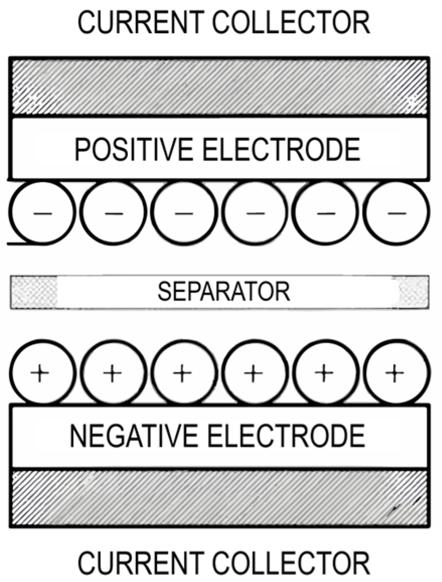
2. Supercapacitors
2.1. Supercapacitor Modeling
2.1.1. Simple RC Model
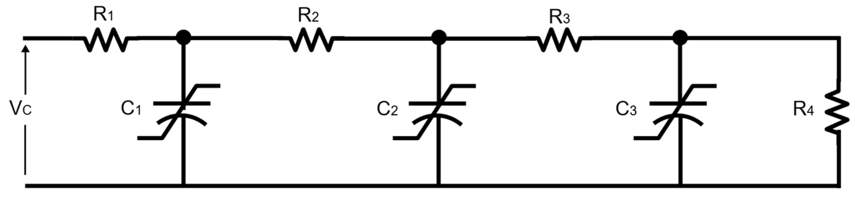
2.1.2. Transmission Line Model
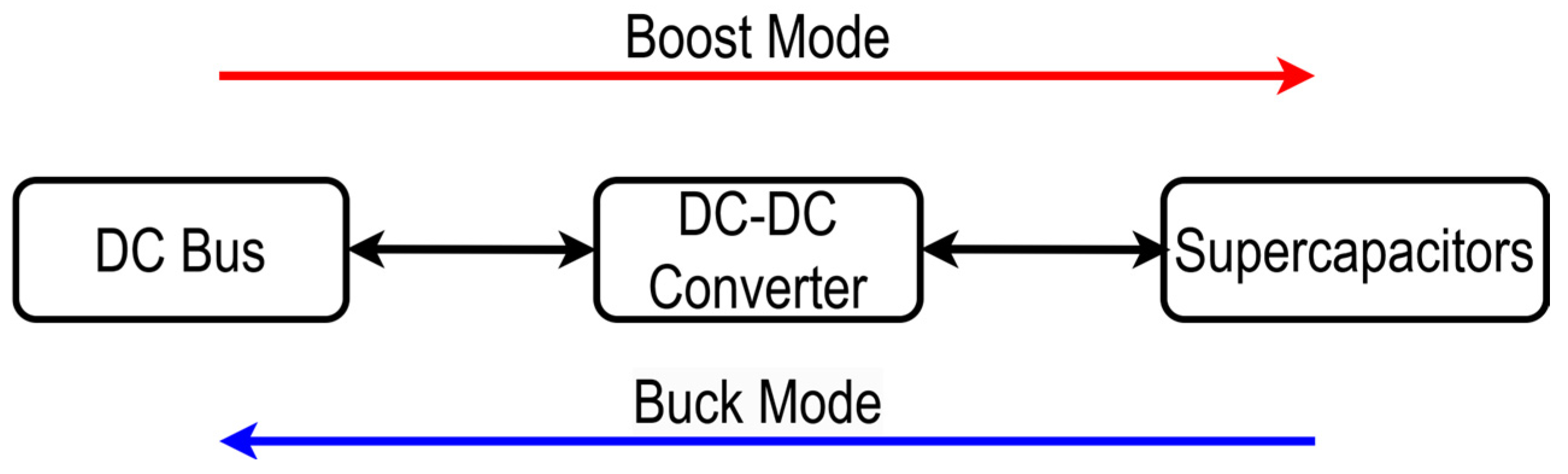
3. Bidirectional DC-DC Converters for Supercapacitors
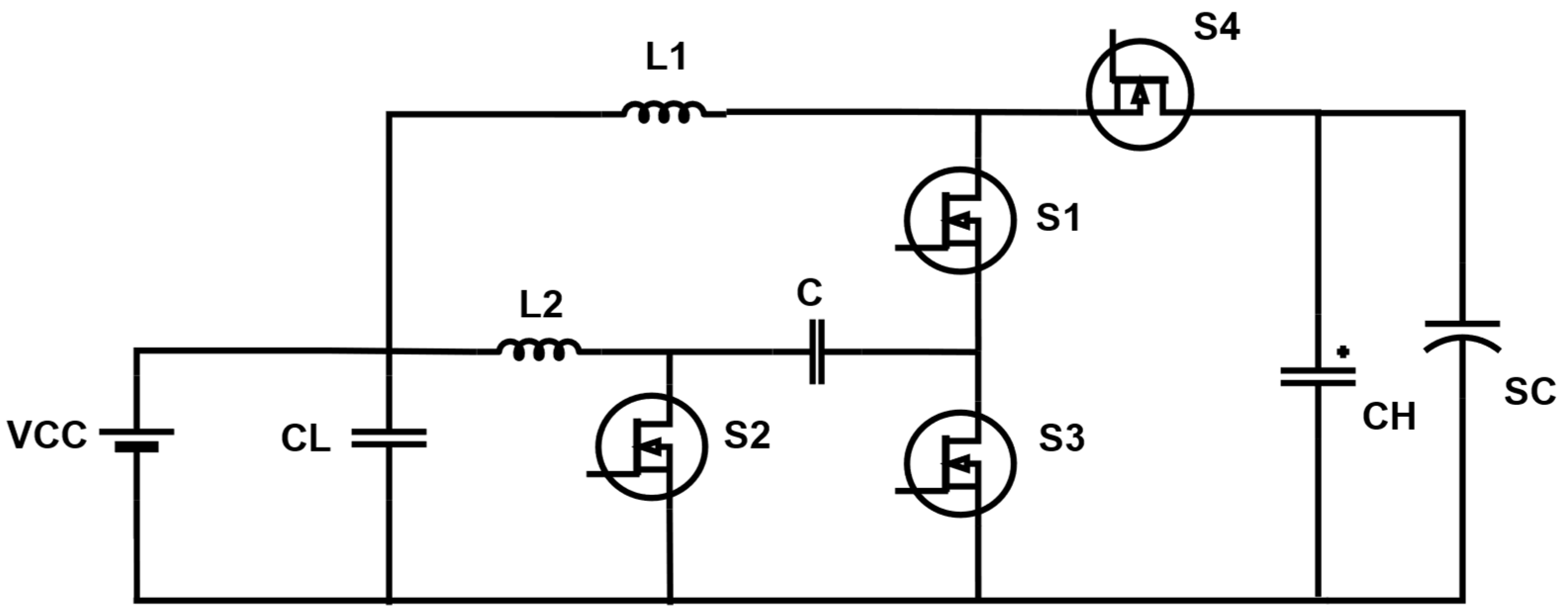
3.1. Bidirectional DC-DC Converter with High Voltage Gain
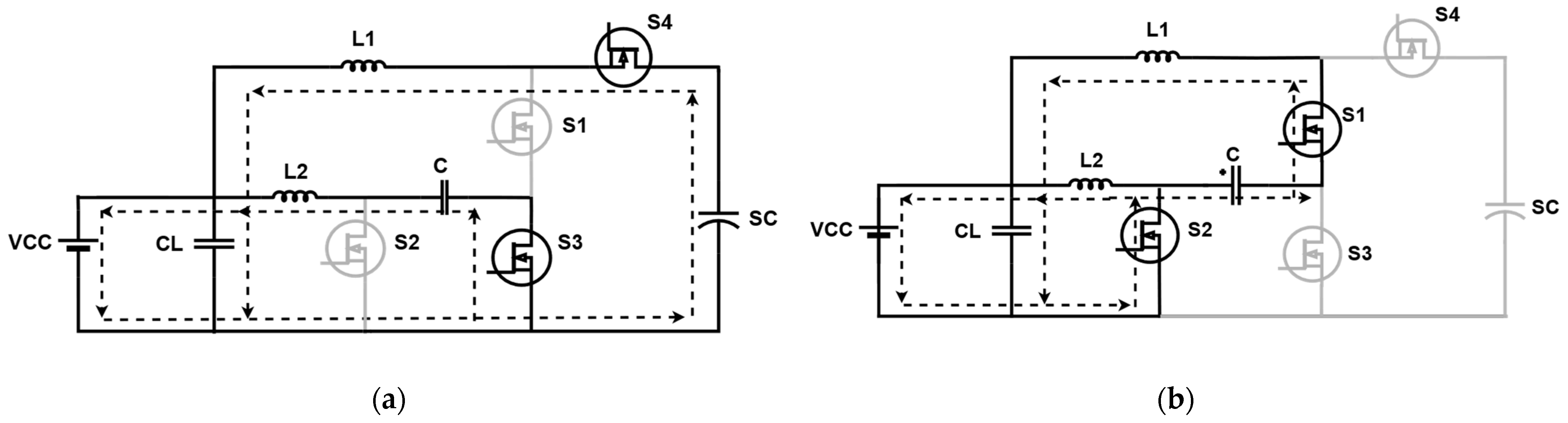
3.1.1. Buck Mode
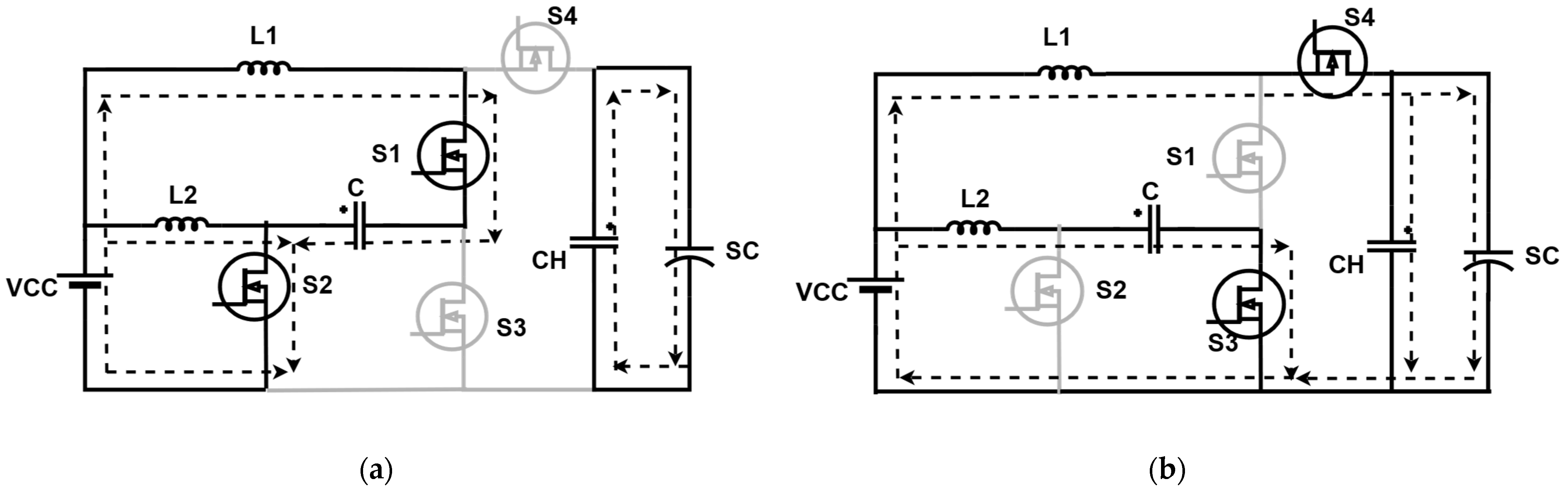
3.1.2. Boost Mode
3.1.3. Design of a High-Voltage-Gain Interleaved Bidirectional Buck–Boost Converter
4. Dynamic Modeling of the Interleaved Buck–Boost Converter with High Voltage Gain
4.1. Buck Operating Mode
4.2. Boost Operating Mode
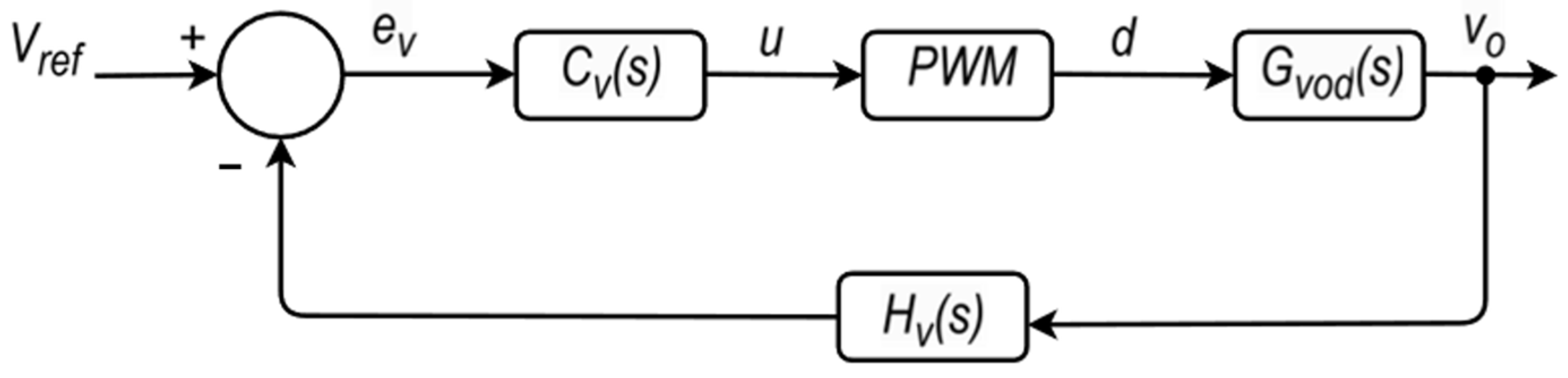
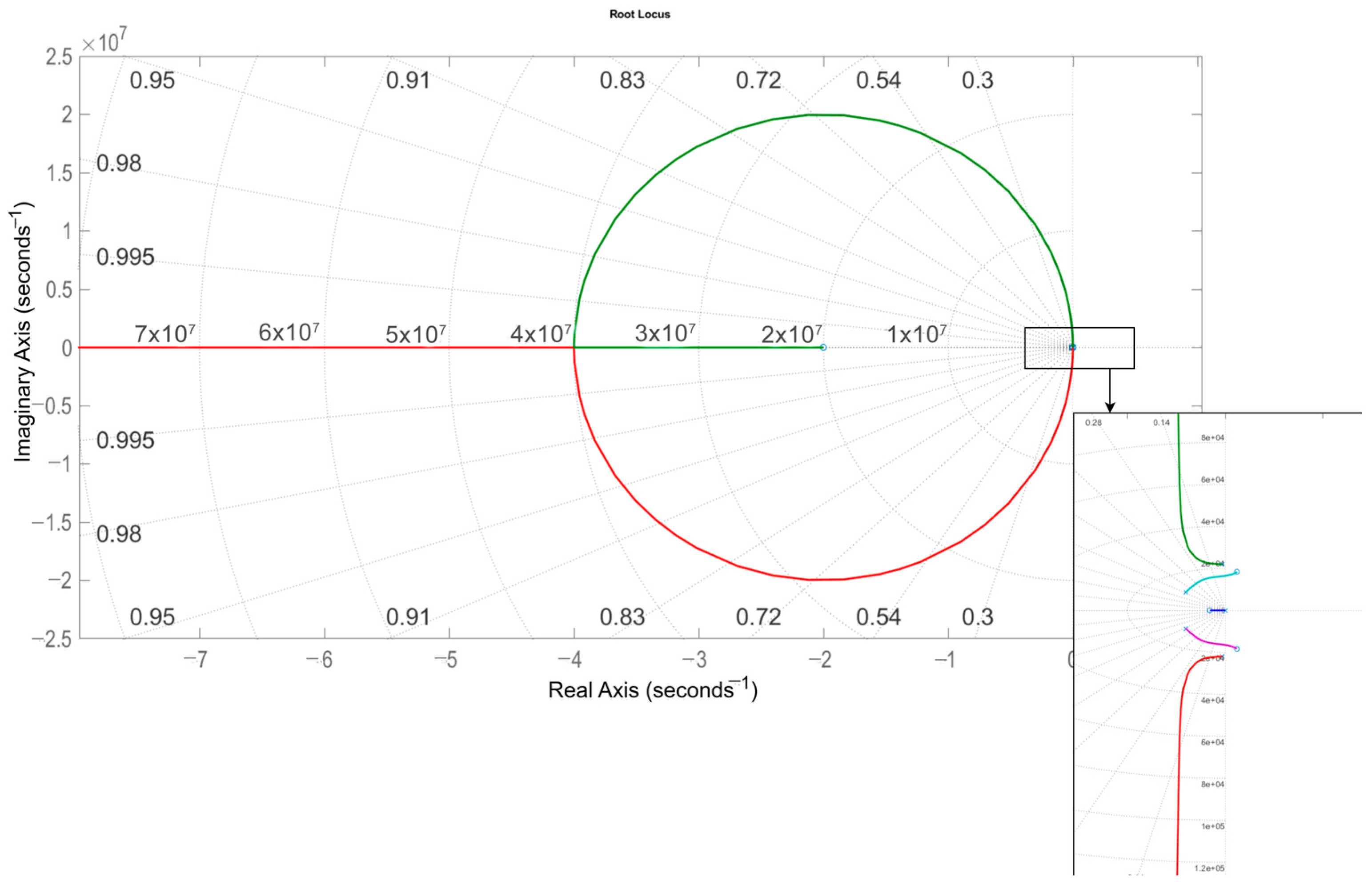
5. Controller Design
5.1. Buck Operating Mode: Results
Analysis of Results—Buck Operation
5.2. Boost Operating Mode
Analysis of Results—Boost Operation
6. Conclusions
Author Contributions
Funding
Data Availability Statement
Acknowledgments
Conflicts of Interest
References
- United Nations. Cumbre de las Naciones Unidas Sobre el Desarrollo Sostenible|Naciones Unidas. Available online: https://www.un.org/es/conferences/environment/newyork2015 (accessed on 8 June 2024).
- International Energy Agency. World Energy Outlook 2023—Analysis. Available online: https://www.iea.org/reports/world-energy-outlook-2023 (accessed on 30 June 2024).
- Calero, F.; Cañizares, C.A.; Bhattacharya, K.; Anierobi, C.; Calero, I.; De Souza, M.F.Z.; Farrokhabadi, M.; Guzman, N.S.; Mendieta, W.; Peral, D.; et al. A Review of Modeling and Applications of Energy Storage Systems in Power Grids. Proc. IEEE 2023, 111, 806–831. [Google Scholar] [CrossRef]
- Badal, F.R. Microgrid to smart grid’s evolution: Technical challenges, current solutions, and future scopes. Energy Sci. Eng. 2023, 11, 874–928. [Google Scholar] [CrossRef]
- Tabora, J.M.; Paixão Júnior, U.C.; Rodrigues, C.E.M.; Bezerra, U.H.; Tostes, M.E.D.L.; Albuquerque, B.S.D.; Matos, E.O.D.; Nascimento, A.A.D. Hybrid System Assessment in On-Grid and Off-Grid Conditions: A Technical and Economical Approach. Energies 2021, 14, 5284. [Google Scholar] [CrossRef]
- Do Nascimento, A.L.L.; De Albuquerque, B.S.; Filho, E.O.R.; Tabora, J.M.; Brilhante, M.G.; De Rocha, L.J.M.; Carrera, D.P.R.; De Moura Carvalho, C.C.M.; De Lima Tostes, M.E.; Monteiro, E.K.C.; et al. Battery Energy Storage Systems Operation in a Hybrid Renewable System. In Proceedings of the 2023 IEEE Colombian Caribbean Conference (C3), Barranquilla, Colombia, 22–25 November 2023; pp. 1–6. [Google Scholar] [CrossRef]
- Martin-Martínez, F.; Sánchez-Miralles, A.; Rivier, M. A literature review of Microgrids: A functional layer based classification. Renew. Sustain. Energy Rev. 2016, 62, 1133–1153. [Google Scholar] [CrossRef]
- Corti, F.; Laudani, A.; Lozito, G.M.; Palermo, M.; Quercio, M.; Pattini, F.; Rampino, S. Dynamic Analysis of a Supercapacitor DC-Link in Photovoltaic Conversion Applications. Energies 2023, 16, 5864. [Google Scholar] [CrossRef]
- Ahmed, O.A.; Bleijis, J.A.M. An Overview of DC–DC Converter Topologies for Fuel Cell-Ultracapacitor Hybrid Distribution System. Renew. Sustain. Energy Rev. 2015, 42, 609–626. [Google Scholar] [CrossRef]
- Wang, J.; Wang, B.; Zhang, L.; Wang, J.; Shchurov, N.I.; Malozyomov, B.V. Review of bidirectional DC–DC converter topologies for hybrid energy storage system of new energy vehicles. Green Energy Intell. Transp. 2022, 1, 100010. [Google Scholar] [CrossRef]
- Hussain, A.; Mohamed, M.M.; Aijaz, M.O.; Karim, M.R.; Aziz, M.A. Electrospun PEI/PAN membrane for advanced Zn ion hybrid supercapacitors. J. Energy Storage 2024, 84, 110974. [Google Scholar] [CrossRef]
- Hu, W.; Liu, X.; Pang, Y.; Li, A.; Lyu, Z.; Li, Q. A functional interlayer of PVDF-CTFE/MCA-HOFs for inhibiting zinc dendrite growth to improve the performance of aqueous zinc-ion batteries. J. Alloys Compd. 2025, 1022, 179843. [Google Scholar] [CrossRef]
- Mohamed, M.M.; Hussain, A.; Rezaul Karim, M.; Faisal Al-Betar, A.-R.; Aziz, A. N-doped polyacrylonitrile carbon fiber interlayer for uniform and dendrite free Zn metal battery. Appl. Surf. Sci. 2025, 680, 161347. [Google Scholar] [CrossRef]
- Davies, T.S.; Jefferson, C.M.; Larsen, N.; Nouri, H. DC-DC Power Conversion for Supercapacitor Energy Storage System. In Proceedings of the 31st Universities Power Engineering Conference, Heraklion, Greece, 18–20 September 1999; pp. 289–292. [Google Scholar]
- Jefferson, C.M.; Neilson, K. In Proceedings of the 29th Universities Power Engineering Conference, Hosted by Department of Electrical Engineering, University College: Conference Proceedings, Galway, Ireland, 14–16 September 1994; pp. 275–277.
- Andrade, V.B.; Paixão, U.C., Jr.; Moreira, C.E.; Soares, T.M.; Tabora, J.M.; Tostes, M.E.D.L.; Bezerra, U.H.; Albuquerque, B.; Gouveia, L.D.S. Modelagem de um sistema de distribuição real desbalanceado e análise do impacto da geração distribuída utilizando o software OpenDSS. In Proceedings of the Anais do Simpósio Brasileiro de Sistemas Elétricos 2020, Santo André, SP, Brazil, 25–28 August 2020. [Google Scholar] [CrossRef]
- Moreira, G.A.M.; Tabora, J.M.; Soares, T.M.; De Lima Tostes, M.E.; Bezerra, U.H.; De Carvalho, C.C.M.; De Matos, E.O. Demand Side Management Strategies for the Introduction of Electric Vehicles: A Case Study. In Proceedings of the 2023 IEEE Colombian Caribbean Conference (C3), Barranquilla, Colombia, 22–25 November 2023; pp. 1–6. [Google Scholar] [CrossRef]
- Mendes, N.; Tabora, J.M.; de Lima Tostes, M.E.; de Matos, E.O.; H.Bezerra, U.; Moura, P.; Mendes, J.; Ferreira, F.J.T.E.; de Almeida, A.T. ANN for Motor Loading Diagnosis under Voltage Variation Conditions. In Proceedings of the 2023 IEEE Kansas Power and Energy Conference (KPEC), Manhattan, KS, USA, 27–28 April 2023; pp. 1–6. [Google Scholar] [CrossRef]
- Serpi, A.; Porru, M.; Damiano, A. An Optimal Power and Energy Management by Hybrid Energy Storage Systems in Microgrids. Energies 2017, 10, 1909. [Google Scholar] [CrossRef]
- Duke Energy. Duke Energy to Put New Battery and Ultracapacitor System to the Test in N.C. Available online: https://news.duke-energy.com/releases/duke-energy-to-put-new-battery-and-ultracapacitor-system-to-the-test-in-n-c (accessed on 7 July 2023).
- Endesa, S.A. La Graciosa, the Intelligent Energy Island. Available online: https://www.endesa.com/en/projects/all-projects/energy-transition/smart-grids/la-graciosa-the-intelligent-energy-island (accessed on 7 July 2023).
- Hosseinalizadeh, R.; Shakouri, H.G.; Amalnick, M.S.; Taghipour, P. Economic sizing of a hybrid (PV–WT–FC) renewable energy system (HRES) for stand-alone usages by an optimization-simulation model: Case study of Iran. Renew. Sustain. Energy Rev. 2016, 54, 139–150. [Google Scholar] [CrossRef]
- Smart Energy City Project: An Australian Perspective to a Large DER Intensive Microgrid-IEEE Smart Grid. Available online: https://smartgrid.ieee.org/bulletins/november-2018/smart-energy-city-project-an-australian-perspective-to-a-large-der-intensive-microgrid (accessed on 8 July 2023).
- Zhu, Y.; Li, X.; Liu, Q.; Li, S.; Xu, Y. Review Article: A Comprehensive Review of Energy Management Strategies for Hybrid Electric Vehicles. Mech. Sci. 2022, 13, 147–188. [Google Scholar] [CrossRef]
- Ramos, G.A.; Costa-Castelló, R. Energy Management Strategies for Hybrid Energy Storage Systems Based on Filter Control: Analysis and Comparison. Electronics 2022, 11, 1631. [Google Scholar] [CrossRef]
- Wang, Y.; Lucia, O.; Zhang, Z.; Gao, S.; Guan, Y.; Xu, D. A Review of High Frequency Power Converters and Related Technologies. IEEE Open J. Ind. Electron. Soc. 2020, 1, 247–260. [Google Scholar] [CrossRef]
- Gorji, S.A.; Sahebi, H.G.; Ektesabi, M.; Rad, A.B. Topologies and Control Schemes of Bidirectional DC–DC Power Converters: An Overview. IEEE Access 2019, 7, 117997–118019. [Google Scholar] [CrossRef]
- Gürçam, K.; Almalı, M.N. A High-Efficiency Single-Stage Isolated Sepic-Flyback AC–DC Led Driver. Electronics 2023, 12, 4946. [Google Scholar] [CrossRef]
- Wang, Z.; Su, X.; Zeng, N.; Jiang, J. Overview of Isolated Bidirectional DC–DC Converter Topology and Switching Strategies for Electric Vehicle Applications. Energies 2024, 17, 2434. [Google Scholar] [CrossRef]
- Ardi, H.; Ajami, A.; Kardan, F.; Avilagh, S.N. Analysis and Implementation of a Nonisolated Bidirectional DC–DC Converter with High Voltage Gain. IEEE Trans. Ind. Electron. 2016, 63, 4878–4888. [Google Scholar] [CrossRef]
- Mumtaz, F.; Yahaya, N.Z.; Meraj, S.T.; Singh, N.S.S.; Abro, G.E.M. A Novel Non-Isolated High-Gain Non-Inverting Interleaved DC–DC Converter. Micromachines 2023, 14, 585. [Google Scholar] [CrossRef]
- Wang, H.; Wang, P.; Yan, E.; Wang, W.; Xu, D. A Review of Non-Isolated High-Gain Y-Source Converters Topologies. Energies 2024, 17, 2850. [Google Scholar] [CrossRef]
- Biswal, P.; Bhajana, V.V.S.K.; Iqbal, A.; Kakani, V.; Popuri, M. Extended high gain DC-DC converter with switched-inductors, switched-capacitors and soft-switching: Analysis and implementation. IET Power Electron. 2024, 17, 1445–1456. [Google Scholar] [CrossRef]
- Sethi, B.; Mitra, L. Design and implementation of grid tied high step-up DC-DC converter with switched capacitor. Int. J. Power Electron. Drive Syst. 2024, 15, 323–334. [Google Scholar] [CrossRef]
- Mohammadi, P.; Samanbakhsh, R.; Hernandez, F.D.; Koohi, P.; Ibanez, F. A Novel Non-Coupled Non-Isolated Double-Input Bidirectional High-Gain Converter for Hybrid Energy Storage System. In Proceedings of the 2019 IEEE 10th International Symposium on Power Electronics for Distributed Generation Systems (PEDG), Xi’an, China, 3–6 June 2019; pp. 531–536. [Google Scholar] [CrossRef]
- Chong, L.W.; Wong, Y.W.; Rajkumar, R.K.; Rajkumar, R.K.; Isa, D. Hybrid Energy Storage Systems and Control Strategies for Stand-Alone Renewable Energy Power Systems. Renew. Sustain. Energy Rev. 2016, 66, 174–189. [Google Scholar] [CrossRef]
- Gee, A.M.; Robinson, F.V.P.; Dunn, R.W. Analysis of Battery Lifetime Extension in a Small-Scale Wind-Energy System Using Supercapacitors. IEEE Trans. Energy Convers. 2013, 28, 24–33. [Google Scholar] [CrossRef]
- Kollimalla, S.K.; Mishra, M.K.; Narasamma, N.L. Design and Analysis of Novel Control Strategy for Battery and Supercapacitor Storage System. IEEE Trans. Sustain. Energy 2014, 5, 1137–1144. [Google Scholar] [CrossRef]
- Kroičs, K.; Staņa, Ģ. Bidirectional Interleaved DC–DC Converter for Supercapacitor Energy Storage Integration with Reduced Capacitance. Electronics 2023, 12, 126. [Google Scholar] [CrossRef]
- Broday, G.R.; Nascimento, C.B.; Agostini, E.; Lopes, L.A.C. A bidirectional DC-DC converter For Supercapacitors in Hybrid Energy Storage Systems. In Proceedings of the 2017 11th IEEE International Conference on Compatibility, Power Electronics and Power Engineering (CPE-POWERENG), Cadiz, Spain, 4–6 April 2017; pp. 298–303. [Google Scholar] [CrossRef]
- Lencwe, M.J.; Olwal, T.O.; Chowdhury, S.D.; Sibanyoni, M. Nonsolitary two-way DC-to-DC converters for hybrid battery and supercapacitor energy storage systems: A comprehensive survey. Energy Rep. 2024, 11, 2737–2767. [Google Scholar] [CrossRef]
- Garcia-Torres, F.; Bordons, C. Optimal Economical Schedule of Hydrogen-Based Microgrids with Hybrid Storage Using Model Predictive Control. IEEE Trans. Ind. Electron. 2015, 62, 5195–5207. [Google Scholar] [CrossRef]
- Ghorashi Khalil Abadi, S.A.; Habibi, S.I.; Khalili, T.; Bidram, A. A Model Predictive Control Strategy for Performance Improvement of Hybrid Energy Storage Systems in DC Microgrids. IEEE Access 2022, 10, 25400–25421. [Google Scholar] [CrossRef]
- Song, Y.D.; Cao, Q.; Du, X.; Karimi, H.R. Control Strategy Based on Wavelet Transform and Neural Network for Hybrid Power System. J. Appl. Math. 2013, 2013, 1–8. [Google Scholar] [CrossRef]
- Kim, S.-M.; Sul, S.-K. Control of Rubber Tyred Gantry Crane with Energy Storage Based on Supercapacitor Bank. IEEE Trans. Power Electron. 2006, 21, 1420–1427. [Google Scholar] [CrossRef]
- Chakole, R.; Palandurkar, M.V.; Renge, M.M. Energy management of supercapacitor with DC-DC converter. In Proceedings of the 2016 IEEE 1st International Conference on Power Electronics, Intelligent Control and Energy Systems (ICPEICES), Delhi, India, 4–6 July 2016; pp. 1–6. [Google Scholar] [CrossRef]
- Ali, U.S.; Saravanan, D.; Shreya, S.; Prahaladh, M.R. Quasi Z-source DC-DC Converter with Supercapacitor for Photovoltaic Application. In Proceedings of the 2022 3rd International Conference for Emerging Technology (INCET), Belgaum, India, 27–29 May 2022; pp. 1–6. [Google Scholar] [CrossRef]
- Enang, C.M.; Johnson, B.K. Bidirectional dc-dc Converter Control in Battery-Supercapacitor Hybrid Energy Storage System. In Proceedings of the 2020 IEEE Power & Energy Society Innovative Smart Grid Technologies Conference (ISGT), Washington, DC, USA, 17–20 February 2020; pp. 1–5. [Google Scholar] [CrossRef]
- Samanta, A.; Huynh, A.; Sharma, M.; Marcis, V.; Williamson, S. Supercapacitor and Bidirectional DC-DC Converter-based Active Charge Balancing Scheme for Lithium-ion Batteries. In Proceedings of the 2022 IEEE Energy Conversion Congress and Exposition (ECCE), Detroit, MI, USA, 9–13 October 2022; pp. 1–7. [Google Scholar] [CrossRef]
- Saichand, K.; John, V. Adaptive control strategy for ultracapacitor basec bidirectional dc-dc converters. In Proceedings of the 2017 IEEE Applied Power Electronics Conference and Exposition (APEC), Tampa, FL, USA, 26–30 March 2017; pp. 1167–1174. [Google Scholar] [CrossRef]
- Zhang, J.; Lai, J.-S.; Yu, W. Bidirectional DC-DC converter modeling and unified controller with digital implementation. In Proceedings of the 2008 Twenty-Third Annual IEEE Applied Power Electronics Conference and Exposition, Austin, TX, USA, 24–28 February 2008; pp. 1747–1753. [Google Scholar] [CrossRef]
- Grbovic, P.J. Ultra-Capacitors in Power Conversion Systems; John Wiley & Sons: Hoboken, NJ, USA, 2013. [Google Scholar]
- Şahin, M.; Blaabjerg, F.; Sangwongwanich, A. A Comprehensive Review on Supercapacitor Applications and Developments. Energies 2022, 15, 674. [Google Scholar] [CrossRef]
- Zhang, L.; Hu, X.; Wang, Z.; Sun, F.; Dorrell, D.G. A review of supercapacitor modeling, estimation, and applications: A control/management perspective. Renew. Sustain. Energy Rev. 2018, 81, 1868–1878. [Google Scholar] [CrossRef]
- Ferreira, A.A.; Pomilio, J.A. Estado da Arte sobre a Aplicação de Supercapacitores em Eletrônica de Potência. Eletrônica Potência 2005, 10, 25–32. [Google Scholar] [CrossRef]
- Halper, M.S.; Ellenbogen, J.C. Supercapacitors: A Brief Overview; The MITRE Corporation: McLean, VA, USA, 2006. [Google Scholar]
- Şahin, M.; Blaabjerg, F.; Sangwongwanich, A. Predesign Simulation of Supercapacitors Based on Simplified Equivalent Circuit Model. In Proceedings of the CYSENI 2019, Kaunas, Lithuania, 23–24 May 2019. [Google Scholar]
- Ma, N.; Yang, D.; Riaz, S.; Wang, L.; Wang, K. Aging Mechanism and Models of Supercapacitors: A Review. Technologies 2023, 11, 38. [Google Scholar] [CrossRef]
- Pean, C.; Rotenberg, B.; Simon, P.; Salanne, M. Multi-Scale Modelling of Supercapacitors: From Molecular Simulations to a Transmission Line Model. J. Power Sources 2016, 326, 680–685. [Google Scholar] [CrossRef]


| Paper | Converter Topology | Control Strategy | Applications | Observations |
|---|---|---|---|---|
| [31] | Dual boost with four switches and passive components. | PWM for power and voltage regulation. | Fuel cells, batteries, and renewable energy systems. | High efficiency and voltage gain; simple design, but more components and higher cost. |
| [47] | Quasi Z-source DC-DC converter. | MPPT using Perturb and Observe (P&O) algorithm. | Photovoltaic systems with supercapacitor energy storage. | Efficient PV–supercapacitor interface; sensitive to rapid irradiance changes. |
| [48] | Separate converters for battery and supercapacitor. | Frequency-based control with PI for duty cycle adjustment. | Power regulation, grid support, and energy backup. | Flexible and stable; requires precise measurements and involves higher complexity. |
| [49] | Supercapacitor + C2P2C DC-DC converter. | Active cell balancing by modulating charging/discharging. | Electric vehicles and storage systems. | Improved voltage balance; fewer components, but requires accurate parameter estimation. |
| [50] | Bidirectional DC-DC converter (boost/buck mode) with ultracapacitor | Adaptive PI-based control. | Hybrid EVs, microgrids, backup systems. | Reduces settling time (10–50%); complex design and sensitive to parameter tuning. |
| [46] | Boost converter with series-connected supercapacitors | Open-loop vs. closed-loop with PI controller. | Renewables, electric mobility, motor drive systems. | Stable voltage; needs accurate control to prevent voltage drop. |
| [45] | Inverter-based three-phase converter. | Frequency estimation and dual-mode control. | Rubber-tyred gantry crane (RTGC) for container handling in ports | The system achieves approximately 35% energy savings and over 40% reduction in engine emissions. Limitations include the need for precise control and reliance on simulations for validation |
| [51] | Four-phase interleaved bidirectional converter. | DSP-based unified control. | High-power EVs and fuel cell systems. | Smooth buck/boost transitions with ZVS; requires high sampling and careful design. |
| Parameter | Specification |
|---|---|
| Average supercapacitor voltage | |
| Supercapacitor module capacitance | |
| Supercapacitor module | SKELMOD 162V62F |
| Average DC bus voltage | |
| Average output power | |
| Switching frequency current ripple across inductors | |
| Voltage ripple across DC bus | |
| Voltage ripple across supercapacitor | |
| Semiconductor switches |
| Variable | Specification |
|---|---|
| Duty cycle | |
| Central capacitance | |
| Central capacitor voltage | |
| Inductances | |
| Parasitic resistance of inductors | |
| Inductor current | |
| DC bus resistance | |
| DC bus output capacitance | |
| DC bus output capacitor resistance | |
| Output capacitor voltage | |
| Source-drain resistances | |
| Supercapacitor voltage | |
| Supercapacitor output capacitance | |
| Supercapacitor output capacitor resistance | |
| Calculated supercapacitor resistance | |
| Supercapacitor capacitance | |
| Output voltage on the supercapacitor |
| Parameter | Specification |
|---|---|
| Rated power | |
| Input voltage | |
| Output voltage | |
| Maximum cyclic ratio | |
| Switching frequency | |
| Central capacitance | |
| Output capacitance | |
| Load resistance | |
| Series resistance of inductors | |
| Output capacitor series resistance | |
| Source-drain resistor |
| Parameter | Specification |
|---|---|
| Rated power | |
| Input voltage | |
| Output voltage | |
| Maximum cyclic ratio | |
| Switching frequency | |
| Central capacitance | |
| Output capacitance | |
| Supercapacitor capacitance | |
| Load resistance adopted | |
| Series resistance of the inductors | |
| Output capacitor series resistance | |
| Source-drain resistor |
Disclaimer/Publisher’s Note: The statements, opinions and data contained in all publications are solely those of the individual author(s) and contributor(s) and not of MDPI and/or the editor(s). MDPI and/or the editor(s) disclaim responsibility for any injury to people or property resulting from any ideas, methods, instructions or products referred to in the content. |
© 2025 by the authors. Licensee MDPI, Basel, Switzerland. This article is an open access article distributed under the terms and conditions of the Creative Commons Attribution (CC BY) license (https://creativecommons.org/licenses/by/4.0/).
Share and Cite
Sousa, J.C.A.; Soares, T.M.; Tabora, J.M.; Lott, H.G. Design of a Controller for Supercapacitor’s Bidirectional High-Gain Interleaved Converter. Energies 2025, 18, 2605. https://doi.org/10.3390/en18102605
Sousa JCA, Soares TM, Tabora JM, Lott HG. Design of a Controller for Supercapacitor’s Bidirectional High-Gain Interleaved Converter. Energies. 2025; 18(10):2605. https://doi.org/10.3390/en18102605
Chicago/Turabian StyleSousa, Jessica C. A., Thiago M. Soares, Jonathan M. Tabora, and Hugo G. Lott. 2025. "Design of a Controller for Supercapacitor’s Bidirectional High-Gain Interleaved Converter" Energies 18, no. 10: 2605. https://doi.org/10.3390/en18102605
APA StyleSousa, J. C. A., Soares, T. M., Tabora, J. M., & Lott, H. G. (2025). Design of a Controller for Supercapacitor’s Bidirectional High-Gain Interleaved Converter. Energies, 18(10), 2605. https://doi.org/10.3390/en18102605