1. Introduction
Brazil stands out for its energy matrix with a high proportion of renewable sources. At the end of 2022, the data indicate that 47.7% of the country’s internal energy supply comes from renewable sources, while the global average is 14.3%. In the electricity sector, this proportion is even more impressive, with 86.1% of electricity generated coming from renewable sources, almost three times as much as the global average of 29.5% [
1]. As is well known, most of the electricity generated in Brazil comes from hydroelectric plants (58.9%). However, wind and solar energy have also been growing significantly, with a contribution to the electric matrix of approximately 13.2% and 7%, respectively. This is great for Brazil, because in addition to having lower operating costs, plants that generate energy from renewable sources generally emit much less greenhouse gases.
As mentioned before, despite the recent growth in hydraulic, solar, and wind energy, a substantial part of the country’s energy production remains susceptible to seasonal rainfall patterns and fluctuations in solar and wind conditions. The reduction in the storage capacity of water reservoirs, combined with climate change, has been impacting the effective capacity of generation and service at the end of the National Integrated System (SIN, in the Brazilian acronym). To meet the electrical load, the National System Operator (ONS) controls the expressive amount and capacity to meet the systemic requirements of reliability and safety to meet the load curve, considering the variability of renewable generation, increasingly present in the system [
2]. Then, it is necessary to activate fossil-fuel-powered thermoelectric power plants (TPPs) to ensure stabilization and flexibility of the energy supply. TPPs act as a strategic reserve, offering an alternative to ensure a constant supply of energy. They can be activated quickly in times of emergency when there are system failures or unexpectedly high demand (at peak hours). TPPs come into operation to meet this demand and avoid blackouts. In the specific case of Brazil, especially in the Amazon, where some regions are not connected to the SIN, TPPs powered by fossil fuels are the main source of energy. However, in recent years, the Federal Government has been discussing increasing the use of thermoelectric plants under the justification of avoiding the emptying of hydroelectric reservoirs and controlling the risks of potential energy rationing [
3].
Thermoelectric power plants are frequently fueled by natural gas, coal, and diesel/heavy fuel oil (HFO). However, the cost of generating electricity in this way is high and increases environmental pollution. The basic operating process of a TPP is based on the conversion of thermal energy, released by the fuel, into mechanical energy, which is then converted into electrical energy. In our case study, part of a thermal power plant powered by internal combustion four-stroke engines using heavy fuel oil (HFO) as working fluid is analyzed. The reason behind burning HFO rather than conventional light oil is due to its lower production cost and higher availability [
4], particularly in regions rich in oil reserves. Diesel cycle engines are also chosen due to their ease of maintenance, wide availability on the market, and efficiency comparable to steam turbines. Their use is also justified by their low cost and rapid implementation compared to other forms of generation.
HFO cannot be used in diesel engines since injection and combustion systems are made for light diesel. Direct use of heavy fuel oil will lead to difficulties with low atomization characteristics, delayed combustion rate, and depositing more carbon [
5]. Proper heating is critical for ensuring less viscosity and an efficient combustion. HFO’s high viscosity is attributed to some of its components such as resin and asphaltene. As a result, its mobility within the reservoir is significantly affected, and the flow resistance during pipeline transport is substantial, requiring heating before it can be pumped through pipes or burned in boilers or engines. These heating systems typically use electric or traditional steam heating methods (coil/oil/gas heating, nuclear heat, waste heat recovery). In the present work, a theoretical case study of a steam generator used in a real thermoelectric power plant is performed in order to create and validate its thermodynamic and combustion model by means of energy analysis. We use the validated model to estimate
emissions and simulate a scenario given by the substitution of a conventional fuel boiler for an electrical one. In our case, the fuel steam generator burns heavy fuel oil (HFO) to reduce the viscosity of the HFO used by the vapor generator itself and mainly to power the internal combustion engines responsible for generating electrical energy in the plant. As is well known, HFO combustion emits significant quantities of carbon dioxide (
) and other greenhouse gases, contributing to climate change. HFO is a fuel widely used on ships and due to its harmful effects on the environment, mainly due to its relatively poor atomization characteristic, low combustion quality, and high content of polluting elements, the International Maritime Organization (IMO) has regulated the maximum sulfur content in the fuel, as well as the
and
emissions produced by its combustion [
6,
7]. Therefore, to overcome problems like this, it is crucial to understand how an HFO steam generator works, its energy consumption and
production, especially in the case where the TPP operates in standby mode (when requires the use of this type of steam generator 100% of the operational time). Some solutions to minimize its use have been implemented, such as the production of ultra-low sulfur fuel oil (ULSFO), very low sulfur fuel oil (VLSFO), the replacement of HFO by liquefied natural gas (LNG) [
8], and more recently, the replacement of fuel-fired boilers with electric ones [
9]. In this work, a case study (under the same operating conditions - standby mode) is also proposed to replace the fossil fuel (HFO)-fired boiler with two lower capacity electric boilers to develop a brief and simple thermo-economic analysis, while considering that this replacement ensures zero pollutant gas emissions into the atmosphere.
Rising fuel costs and environmental challenges have become significant concerns for contemporary society, motivating engineers and scientists to focus on enhancing the efficiency of steam generators. Then, energy analysis is useful to highlight several aspects of steam generating cycles and calculate general quantities of energy, work, and heat flows [
10]. In [
11], the first law of thermodynamics was used to determine the efficiency of a steam generator that burns solid fuel with a high moisture content; along the same lines, ref. [
12] used the energy loss method in order to analyze the efficiency of steam generators. In [
10], the chosen assessment method was an exergy analysis of a boiler, which takes into account, heat transfer between exhaust gases and working fluid and also the combustion process itself. Other simple methods as the direct method or input output method are preferred by other authors. In terms of
emissions calculation, ref. [
13] adopted a simplified method using the chemical reaction of carbon combustion to compare the
emissions for different types of fuels. In the current work, energy and chemical equation balances are used to validate the models and perform the analyses.
As previously mentioned, diesel engines powered by HFO are still widely used today, not only in land, maritime, aerial, and agricultural vehicles but also in industries and thermoelectric power plants. Although the dynamic viscosity, latent heat of evaporation, and density of HFO are higher than those of LFO, leading to significantly worse emissions, its low production cost and availability have hindered its replacement, despite numerous alternatives studied by researchers, such as the use of blends with natural gas or hydrogen. Therefore, the main objective of the case study presented in this work is to introduce an initial attempt to reduce HFO consumption for steam generation at the SUAPE II thermoelectric plant by replacing combustion boilers with electric boilers. The main contribution of this work lies in the proposal and validation, using real data, of a theoretical model for HFO combustion. It should be noted that few studies have focused on the combustion characteristics of this fuel from a theoretical perspective, despite the various experimental works available in the literature. Developing an appropriate mathematical model and conducting simulations saves resources and time and also enables the study and exploration of a wider range of conditions compared to real-world experiments. It is important to note that the thermoelectric plant, which is the subject of this study, does not have a thermodynamic mathematical model of its auxiliary boiler, making this the first attempt to develop one. From the standpoint of comparing both steam generation systems, the analyses presented in this work will encourage the use of economically and environmentally viable alternatives, such as electric steam generators.
2. Description of Thermoelectric Power Plant and Steam Generator
In this work, our scope of study is the steam generators of the
Energética Suape II thermoelectric power plant with a total installed capacity of 381.2 MW of electric generation and located in Pernambuco, Brazil. The TPP is equipped with 17 Wärtsilä 20V46F engines powered by diesel oil/HFO; heavy fuel oil is the main fuel for powering the plant, and light fuel oil (LFO) is the backup fuel used for starting or in case of heating (steam generation) of HFO is out of service. Engine cooling water is also preheated with steam to ensure a quick engine starting when required. LFO is more expensive than heavy fuel oil (HFO); therefore, its use is limited to specific operating conditions. Recently, many people who use diesel engines, especially owners of small vessels, have considered switching from expensive light diesel fuel to cheaper heavy fuel oil [
5].
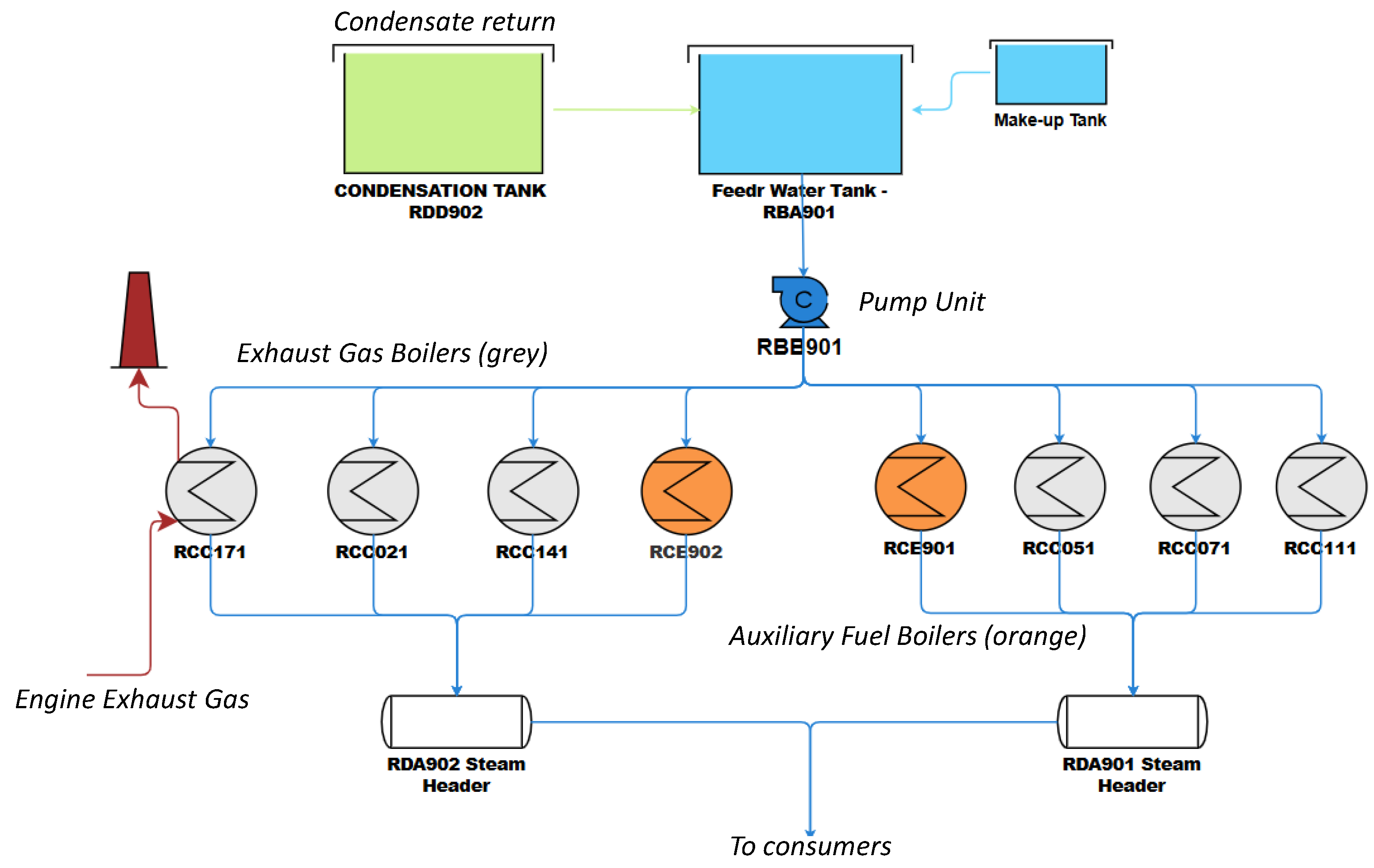
The main source of steam at Suape II TPP is provided by a heat-recovery steam generator (HRSG). This system is composed of energy recovery heat exchangers and boilers that recover waste heat from exhaust gases of engines (as illustrated in
Figure 1). This system is used according to Brazilian energy dispatch system needs (grid failures, unexpected demand surges, or outages in renewable sources) due to the nature of TPPs that represent a fast-response backup power source. The secondary source of steam generation called the auxiliary system is composed of two auxiliary boilers (RCE901 and RCE902). The auxiliary boilers were originally designed to produce steam through the combustion of light fuel oil; however, a modification made to the system allowed one of the boilers (RCE902) to work with HFO, the latter being the object of study of this work. For a better understanding of the steam generating system, see
Figure 1.
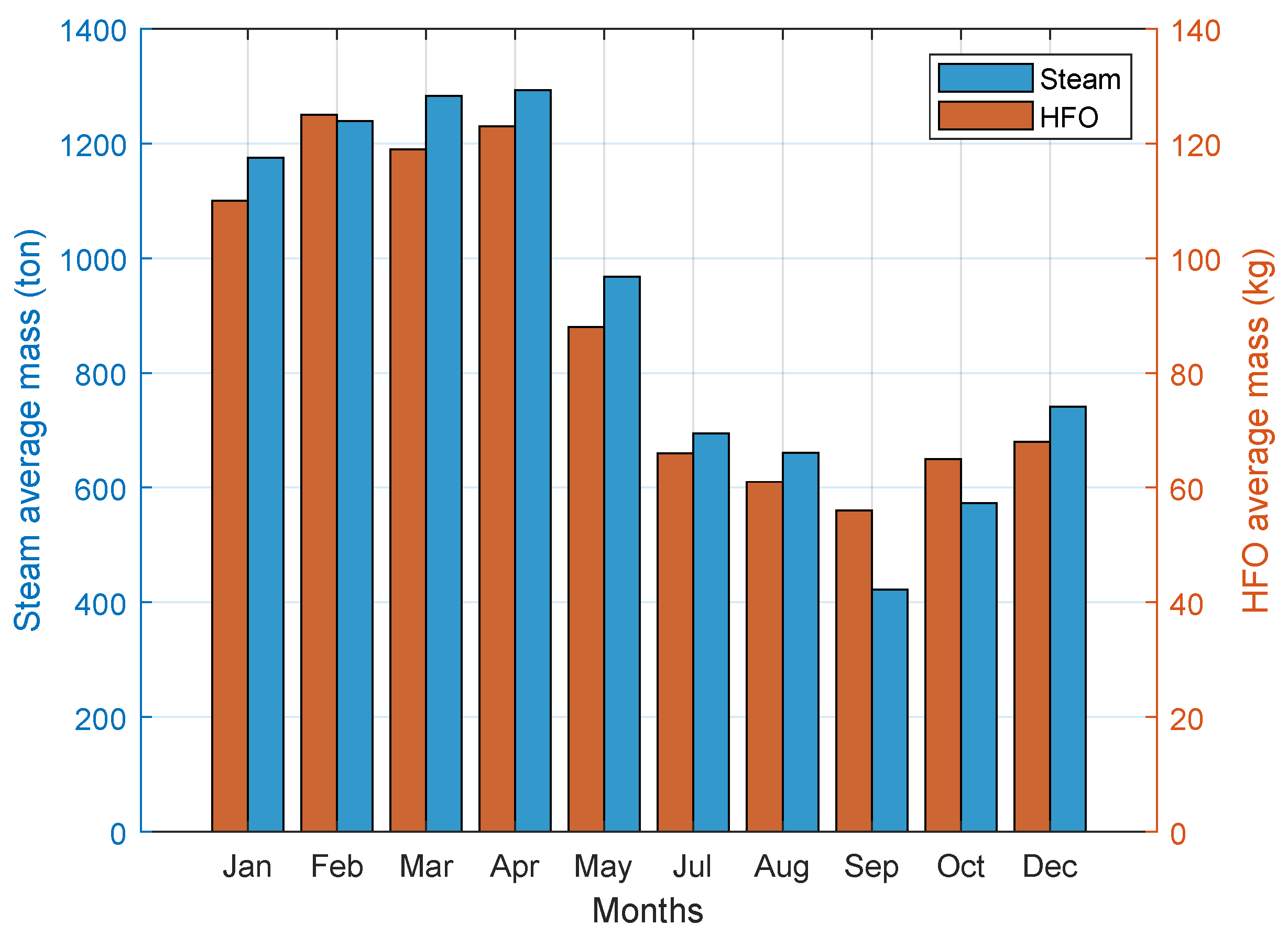
The auxiliary fire-tube boiler (RCE902) operates at 170 °C, 11 bar of pressure, and a maximum capacity of 3000 kg/h. It uses HFO as fuel and transforms its chemical energy into thermal energy that is subsequently transferred to the water (which enters the system at approximately 95 °C), evaporating it through a thermodynamic process. The steam is used not only to heat the fuel for engines but also to keep the fuel warm inside the various tanks (storage, intermediate, daily, and supply) as well as to heat the transport pipes between all of them at strategic points. The complete fuel heating and engine cooling water system is supplied in normal conditions (with the engines running) by the recovery boilers (exhaust gas boilers). On the other hand, the auxiliary boilers are responsible for keeping the daily tanks and engines warm for a quick start as soon as required; this operational mode is called standby. The monthly average data of HFO mass and steam generation, collected over the course of 2024, can be seen in
Figure 2 (excluding June and November, months in which the boiler was not in operation).
3. Methodology
The mathematical modeling of the steam generator is carried out by applying an energy analysis based on the first law of thermodynamics (also known as energy balance) using data provided by the technical documentation and also data collected from real performance of the TPP operating in standby mode during the year 2024.
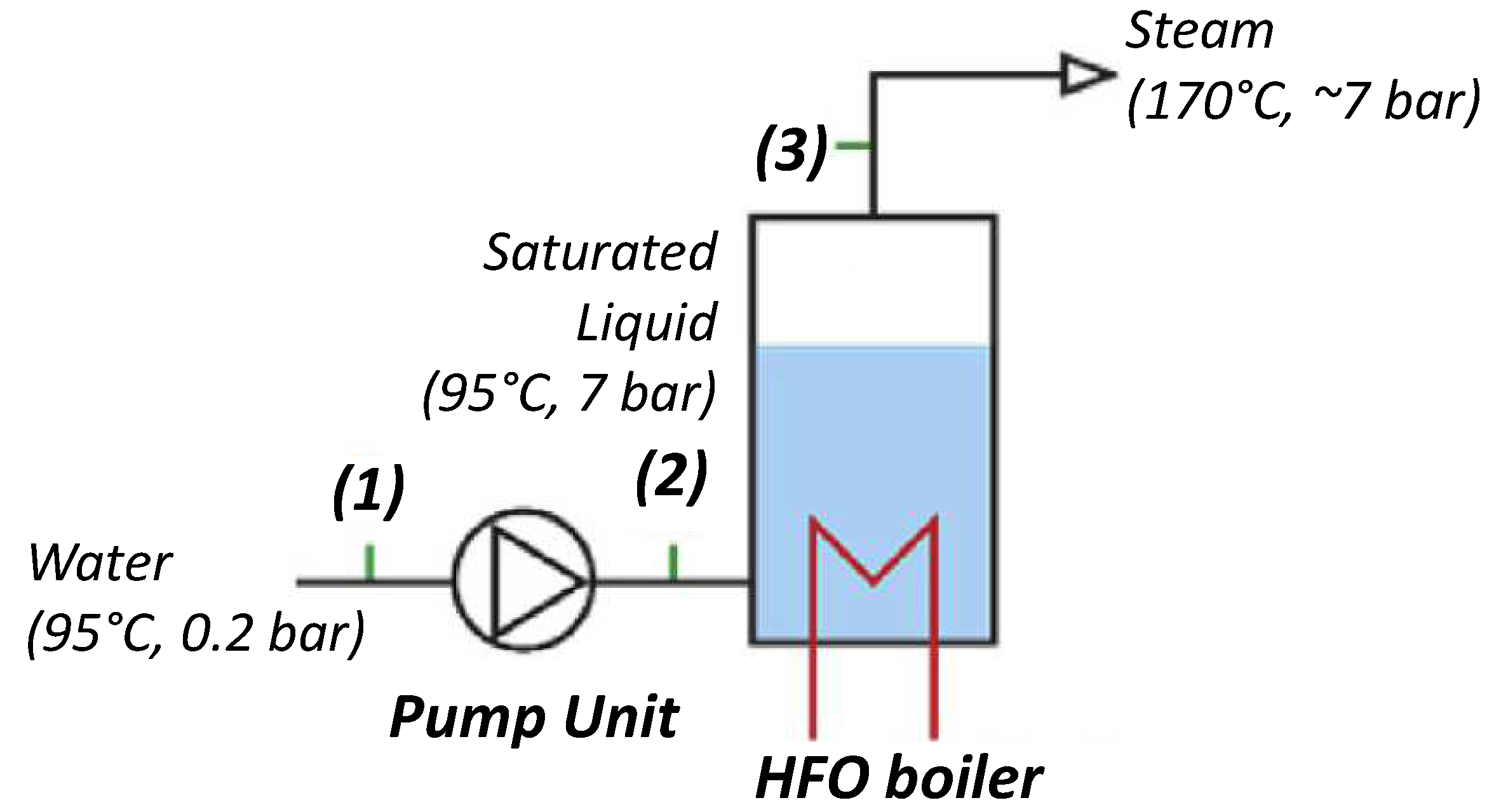
The thermodynamic analysis is divided into two parts: the first one is related to the transformation of saturated liquid water, pumped through the boiler, to superheated vapor before moving to the fuel heating process. The second is associated with the chemical reaction of HFO fuel to produce the desired heat used in the first part.
3.1. Thermodynamic Modeling
In our case study, an HFO boiler called RCE902 at TPP used water with an initial temperature and pressure of 95 °C) and pressure of 0.2 bar (before pump unit) as the starting liquid. The final superheated vapor generated was at 170 °C) and 7 bar (see
Figure 3).
The heat flow (Energy,
[kJ/s]) necessary to evaporate water is calculated as follows:
with
and
being the enthalpy of the liquid/vapor at predefined temperature and pressure (
). The mass flow (
) is extracted from operation data collected during plant operation. The enthalpies are estimated by using thermodynamic tables, available at [
14] and implemented in a computational code developed by authors to create a future thermodynamic model of the entire plant.
3.2. Estimation of the Heat of Combustion
According to [
15], heavy fuel oil (HFO) consists mostly of carbon (86% by weight), hydrogen (11% by weight), and sulfur (the current average is about 3% by weight). In addition, it also includes ash, minerals, and water, among other pollutants. The exact composition of the HFO used at
SUAPE II TPP is unknown. Then, in the present work, a simple chemical formula
without sulfurs is proposed and nitrous oxide (NOX) is not expected as a result of the combustion process. The proposed equation for HFO is based on the literature approximations of hydrocarbon as
with
; it is assumed that
. Other similar approaches have been proposed and validated in other studies, such as in [
7].
To determine the heat of combustion in the exhaust gases, we start by writing the stoichiometric combustion equation for
with oxygen and for 1 kmol of fuel (see Equation (
2)).
Balancing the equation, it is possible to determine the stoichiometric coefficients for each component:
The ideal number of moles of air that guarantees complete combustion is
. Then, the resulting equation is as follows; this is called the theoretical equation without air excess.
The heat of combustion (
), also called the higher heating value (HHV) or calorific value, can be estimated using standard enthalpies of formation and numbers of moles of products (
p) and reactants (
r) of the combustion (see Equation (
5)).
where
is the enthalpy of formation of the substances,
is the enthalpy of substances at an estimated temperature of exhaust gases, and
is the enthalpy at ambient temperature (both calculated based on Tables A18–A26 of [
14]). The enthalpies of formation are considered at 298
(see
Table 1) and extracted from Table A26 of [
14].
Assuming the temperature of the exhaust gases of 2900
, the combustion heat is then estimated as shown in Equation (
6) (that is an expansion of Equation (
5)), and after substituting the values from
Table 1, the results are as shown in Equation (
7).
Using
kg/kmol, the combustion heat per mass unit is:
Finally, the heat energy released by the combustion of HFO can be estimated as shown in Equation (
8) (the use of mass flow in this case study is the average value collected in September 2024, 56 kg/h).
3.3. Case Study Verification
Assuming 10% of the heat loss from the boiler walls, that is, only 90% of the combustion heat of Equation (
8) can be used to generate vapor, the final estimation of the combustion heat is given by Equation (
9):
As previously stated in Equation (
1), it is possible to do an inverse approximation, that is, from the “usable” heat of combustion, estimate whether it is possible to obtain supersaturated steam in the boiler; therefore, we compute the output enthalpy (
) of Equation (
1) using as input the useful heat of combustion of HFO (Equation (
9)). Then:
By using and bar in thermodynamic tables for water, it is easy to verify that boiler output is superheated water with an approximate temperature of 200 °C, which matches the estimated outlet temperature of the steam generator according to the manufacturer’s technical specifications. The manufacturer’s specifications refer to technical drawings of the steam generation system, where estimated values of temperature, pressure, and mass flow along the heat recovery circuit of the exhaust gas boilers and the steam distribution system are detailed. In the results section, other comparisons are made in order to validate the proposed analysis methodology and proposed estimation of HFO composition.
3.4. Emissions Estimation
Once the theoretical equation of combustion has been validated, the resulting stoichiometric coefficients can be used to estimate the amount of emissions
. In order to estimate the
mass flow (
), the product of the number of moles of
by the
–fuel molar mass ratio is calculated and then multiplied by the fuel mass flow (see Equation (
12)). In our case study, the mass flow measured in the boiler through 2024 will be used.
Considering , , , and assuming the average fuel flow in October/2024 (56 kg/h), we obtain kg/s.
3.5. Electric Boilers Analysis
As previously mentioned, with new environmental requirements and challenges to reduce pollutant emissions such as , industrial systems and processes that use fossil fuels are gradually being replaced by equivalent electric systems. In this case study, a preliminary analysis is also proposed to evaluate the replacement of auxiliary steam generator powered by HFO with two lower-capacity electric steam generators.
The electric boilers proposed in the study have a maximum capacity of 500 kg/s and a maximum achievable power between 405 kW and 450 kW. Based on the technical specifications of the boilers and the characteristics of the steam required by the plant, the estimated power is calculated according to Equation (
13).
where
is the mass flow of steam demanded by the plant,
is the enthalpy at the output of electric boiler (
170 °C,
bar),
is the input enthalpy (
20 °C,
bar) and
is the boiler efficiency. To estimate the total cost, the electrical power (
) is multiplied by the unit cost of electricity, which is 87.00 BRL/MWh. For a fuel boiler, the total cost is calculated as the product of the total mass per day and the unit cost of HFO (4.23 BRL/kg).
4. Results and Discussion
As stated in the Methodology section, a combustion model of an HFO steam generator, installed at a thermoelectric power plant (TPP) and used in standby mode during 2024, was proposed. Some assumptions were made due to the lack of specific information and data that are not measured directly at the TPP; one of these assumptions is the temperature of the exhaust gases of the boiler (
), which represents an unknown parameter that will be used to calibrate the validation of the modeling and its influence on the results will be presented below. Other limitations of the model are related to the model construction itself. A simplified equation was assumed for HFO, based on the literature, which establishes that this fuel is composed only of carbon and hydrogen. However, in reality, the composition of this fuel, depending on the location where it was extracted, may contain small amounts of sulfur and nitrogen (see [
4,
15]). This latter statement leads to the simplification that only carbon dioxide is emitted, whereas, in fact, more polluting gases such as nitrogen oxides and sulfur emissions also occur. Still, regarding the composition of HFO, the proposed approximation of
in the formula
has a significant influence, and one of the objectives is to verify, after validation, whether the approximation was reasonable. Concerning the combustion process itself, in this work, it was assumed that the combustion of HFO is complete, whereas in practice, if the air intake into the combustion chamber is not properly controlled, incomplete combustion may lead to carbon monoxide emission (
) in addition to
.
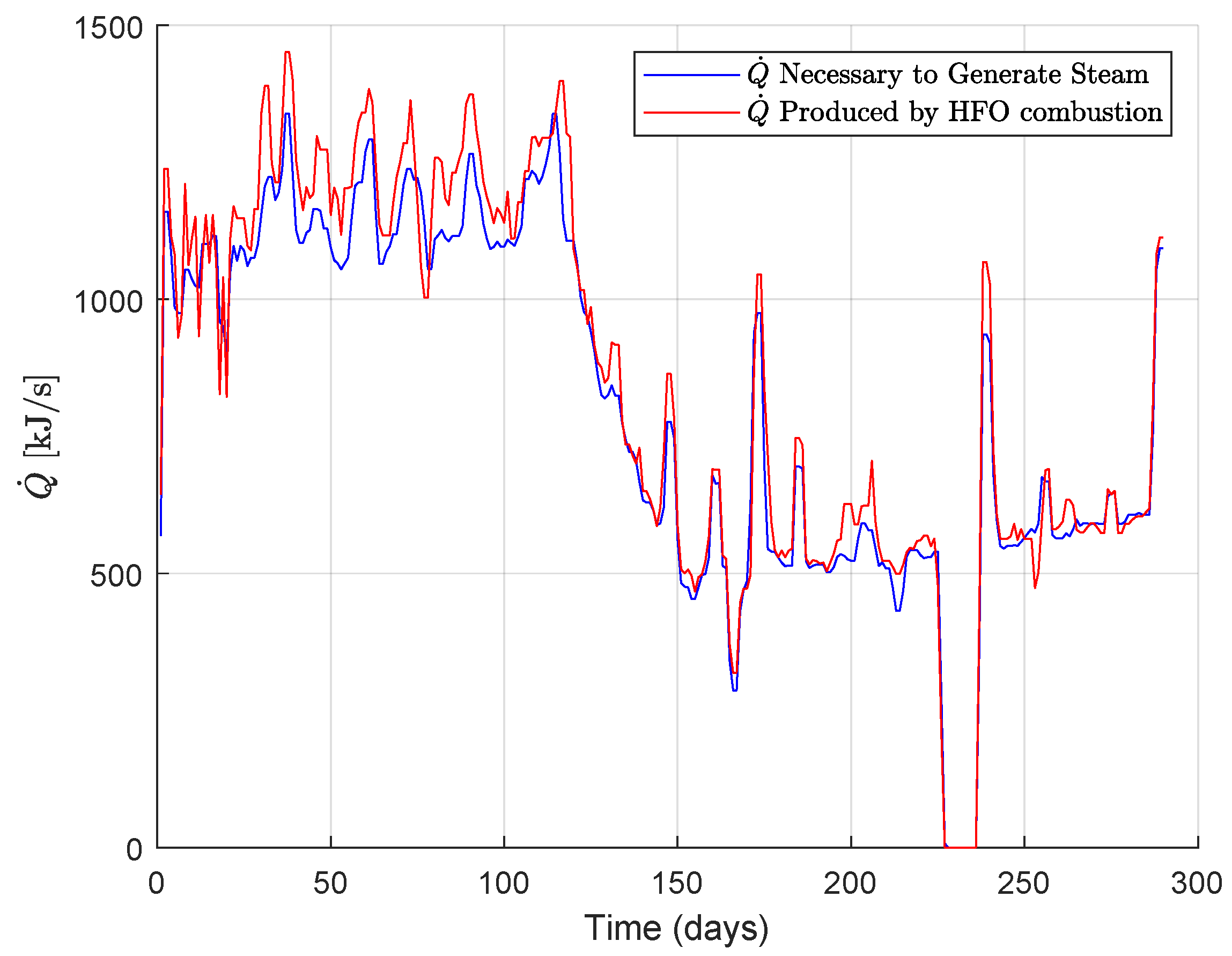
Figure 4 illustrates the behavior of the heat flow throughout the year 2024 (except the months of June and November) assuming
K. It is easy to observe a good fit between the curves, demonstrating that the proposed chemical formula of the HFO is consistent with the reality of the problem. It is also worth noting that both curves depend on real data collected during plant operation, with these data being the mass flows of the fuel and the generated steam.
It was expected that the heat released during the combustion of the HFO would be greater than the heat required to convert water (under the predefined input conditions) into steam (also within the expected temperature range). However, this behavior is not observed in
Figure 4. The case was simulated with
K, and the result seems to be more consistent (see
Figure 5). The HFO combustion heat flow showed in
Figure 5 demonstrates that the proposed chemical formula for HFO,
is accurate enough compared to the heat flow necessary to generate steam. Then, the proposed model is validated. This can be verified by the similarity between the curves in
Figure 5, where both represent, respectively, the mathematical model of two independent thermodynamic processes: steam generation (blue curve), based on the enthalpy increase between boiler inlet and outlet, and the combustion of the liquid HFO fuel (red curve). Both models were fed with independently collected real operational data of the TPP, such as steam and fuel mass flow. Therefore, it can be said that the simplified HFO model proposed,
, resulted in a good approximation for the case study analyzed in terms of the heat generated from the combustion of this fuel, and its use can be extended to other applications.
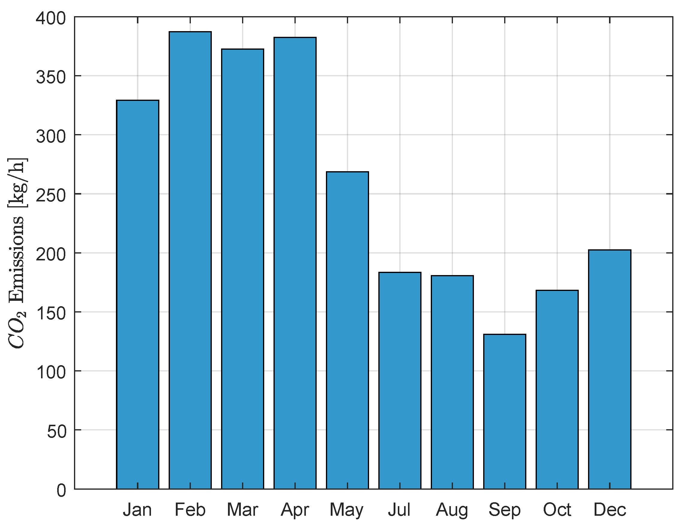
Once the steam generator model has been validated, it is used to estimate carbon dioxide (
) emissions released into the atmosphere during 2024.
Figure 6 illustrates the mass flow of
gases. Summing the mass flow of
emissions over the analyzed months, a total of 62.55 tons of carbon dioxide were produced, which, in the scenario presented below, would no longer be released into the environment.
An analysis of the plant steam generator system was performed in the scenario in which two electric boilers are used as substitutes for the fuel boilers installed currently. As can be seen in
Figure 7, two electric boilers with a maximum power of 450 kW and a maximum steam supply capacity of 500 kg/h would not be sufficient to meet the demand for steam during approximately the first half of the analyzed year. On the other hand, to generate the amount of steam equivalent to the current combustion boiler, the combination of both electric boilers would be able to meet the demand of the second half of the analyzed year at a significantly lower cost, approximately 25% of the cost of fuel (HFO) as illustrated at
Figure 7. The last statement comes from calculating the ratio of the average steam generation cost between electric and fuel-fired boilers, considering only the cost of the required electrical energy and fuel, respectively, and in the current condition, with a low PLD (Settlement Price of Differences), which significantly reduces the cost of electricity in the country. This result is consistent with the statement made in reference [
16], which states that electric boilers result in a 19% energy saving compared to combustion steam boilers.
In terms of maintenance cost, in combustion boilers, it depends mainly on the type of fuel used. Oil-fired boilers have lower maintenance costs because the combustion generates hardly any ash. However, solid fuel has a high percentage of ash that must be removed frequently [
17]. Even in our case study involving a fire-tube boiler using liquid fuel, the piping is subject to corrosion. This acid attack occurs more intensely on the water side, potentially causing leaks and reducing the equipment’s service life. For this reason, it is recommended to conduct periodic laboratory analyses to determine the pH and define the appropriate boiler water treatment. It is also recommended to clean the tubes with a steel brush every 3 to 6 months, depending on the boiler’s usage time, the exhaust gas temperature at the chimney outlet, and the type of fuel used, as well as to remove impurities. Condensate tanks should be inspected and cleaned at least once a year, filters cleaned once a week, and burners should be inspected and cleaned. Monitoring and safety devices such as pressure switches and manometers should be checked and calibrated every three months. Estimating the costs of all these procedures, as well as calculating losses due to inspection downtimes, is not a simple task; however, this analysis will present the average monthly costs recorded at the SUAPE II thermoelectric power plant.
On the other hand, in the case of electric boilers, according to [
18], these systems are more efficient, but for large generation capacities, they are often impractical to install due to the need for large power supply cables and infrastructure requirements. However, actual maintenance costs of electric boilers can be up to 50% lower than those of fuel-fired steam boilers. Generally, the only major components that are periodically replaced are the heating elements themselves, although these are often replaced quickly and cost-effectively. Just like with conventional boilers, it is necessary to check for cleanliness and possible leaks in valves and connections. The flange joints and inspection caps, check valve (return), process controllers and their parameters, motor operation (nominal current), electrical conductors, tightening of the resistance terminals, and other connections in the control panel must be inspected.
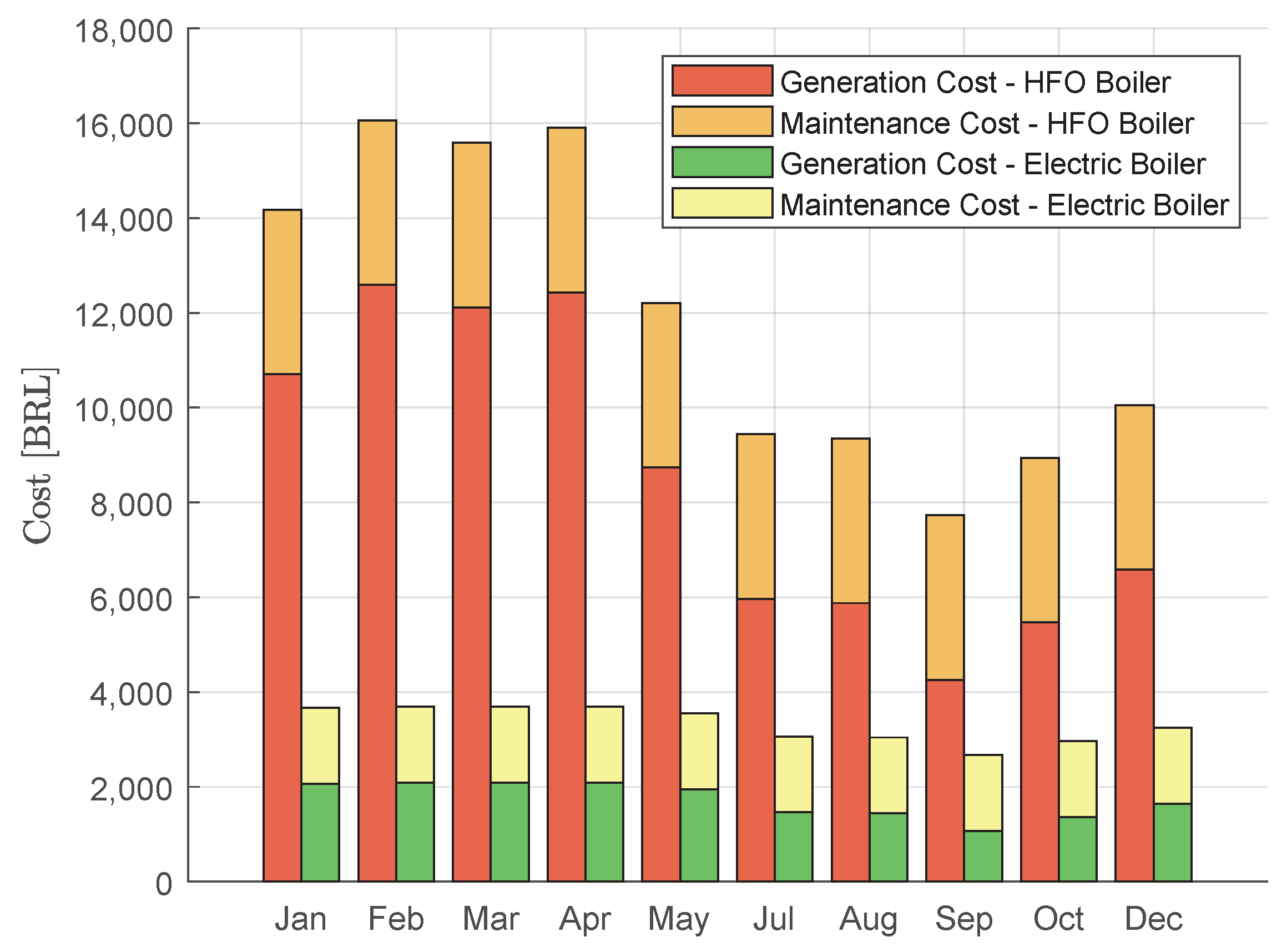
Figure 8 compares the average monthly value required for steam generation and the monthly maintenance cost for both types of steam generators. The approximate fixed monthly cost to perform all the tasks described above, for combustion and electric boilers, is BRL 3470.50 and BRL 1600.00, respectively, according to actual operational data and manufacturer information. The results, which take maintenance costs into account, demonstrate that the total average cost associated with the electric boiler amounts to only 26.81% of the total cost incurred by combustion boilers, highlighting its potential economic advantage.
5. Conclusions
This case study introduced a preliminary thermodynamic and combustion analysis on steam generators used in a thermoelectric power plant that burns heavy fuel oil (HFO). Based on the proposition of a simple HFO chemical formula, a comparison of the thermodynamic model of the steam boiler with the combustion model of the same generator, it was possible to validate the proposed HFO formula. Simulations of both models, using real data collected in 2024 of the steam generator, were compared, demonstrating strong agreement. Once the combustion model was validated, an estimate of carbon dioxide emissions was performed. Finally, taking advantage of the model’s availability, a hypothetical scenario was simulated in which the combustion boiler currently installed in the plant is replaced by two smaller-capacity electric boilers, generating the same amounts of steam demanded throughout 2024. Both cases were compared, and the simulation results and thermo-economic estimates showed that, in fact, upgrading to electric boilers requires between 25% (for steam generation) and 26.81% (also considering maintenance costs) of the financial resources compared to the current combustion boiler. This analysis, of course, considers only the cost of fuel and electricity, respectively. It should be noted that, in addition to the reduction in steam production costs and under the assumption that the electric boiler operates with zero carbon dioxide emissions, the plant would have avoided emitting a total of 62.55 tons of in 2024. Results confirm that electrification is a promising solution for decarbonizing these boilers and encouraging renewable energy sources to generate electricity, which can then be used to power the electric boilers. Despite the simplifications and the unknown exact values of some operational parameters, the proposed combustion model for HFO proved to be consistent with the thermodynamic model of water-to-steam transformation. This enables the future use of the model in other applications. Future work involves improving the existing model by including, for example, and in the formula, performing simulations under incomplete combustion conditions, adjusting parameters such as exhaust gas temperature based on real field data, and so on. A more in-depth analysis, considering investment costs and the determination of financial indicators such as payback period and return on investment, can be carried out.


 ,
, 


