Article

Internet of Things Application in an Automated Irrigation Prototype Powered by Photovoltaic Energy

by
Rafael C. Borges
1,†,
Carlos H. Beuter
2,†,
Vitória C. Dourado
1,† and
Murilo E. C. Bento
3,*
1
Department of Agricultural and Environmental Engineering, Federal University of Rondonópolis, Rondonópolis 78736-900, Brazil
2
Department of Mechanical Engineering, Federal University of Rondonópolis, Rondonópolis 78736-900, Brazil
3
Department of Electrical Engineering, Federal University of Rio de Janeiro, Rio de Janeiro 21941-909, Brazil
*
Author to whom correspondence should be addressed.
These authors contributed equally to this work.
Energies 2024, 17(9), 2219; https://doi.org/10.3390/en17092219
Submission received: 24 March 2024 / Revised: 28 April 2024 / Accepted: 2 May 2024 / Published: 5 May 2024
(This article belongs to the Special Issue Energy Sources from Agriculture and Rural Areas II)

Abstract

:
Small-scale agriculture is important. However, there are still limitations regarding the implementation of technologies in small-scale agriculture due to the high costs accompanying them. Therefore, it is essential to seek viable and low-cost solutions since the insertion of technologies in agriculture, especially irrigated agriculture, guarantees the sustainable expansion of production capacity. The present work applied the Internet of Things concept to an automated irrigation system powered by photovoltaic panels. The materials used in the prototype consisted of Arduino Uno R3, the ESP8266 development board, a soil moisture sensor, a current sensor, a voltage sensor, a flow sensor, and a humidity and temperature sensor. The prototype was designed to take system readings and send them to the Adafruit platform IO. Furthermore, it was programmed to perform remote irrigation control, enabling this to be activated from distant points through the platform. The medium proved efficient for the monitoring and remote control of the system. This indicates that it is possible to use this medium in small automated irrigation systems.

1. Introduction

Food production is a significant factor in a world with increasing population growth; according to research published by the Department of Economic and Social Affairs of the United Nations [1], it is estimated that in the year 2050, the number of inhabitants on the planet will approach 9.7 billion people, an increase of 2 billion individuals over the next 30 years. Furthermore, there is a constant concern about ensuring food security in developing countries since food distribution is not egalitarian [2].
Thus, given the existing and future food demand to supply the population, irrigated agriculture has a high potential to contribute substantially to food production. In Brazil, although the irrigated area is less than 20% of the total cultivated area, it stands out compared to other areas, being responsible for more than 40% of the food, fibre, and bioenergy crops in the country [3].
The insertion of technologies in agriculture, especially irrigated agriculture, guarantees the sustainable expansion of production capacity. At present, several systems use technologies aiming to achieve irrigation management [4]. However, many of them have high costs that make them unaccessible to small producers.
Therefore, as most of the food that reaches Brazilians’ tables comes from family farming, it is essential to think about low-cost, accessible and autonomous projects capable of increasing the intensity, quality, and ease of production [5,6].
Therefore, the present work is based on the development of an automated irrigation prototype using the Arduino microcontroller, photovoltaic energy, and the concept of the Internet of Things (IoT). The use of Arduino in systems is seen as an excellent tool for automatic irrigation control since it is low-cost and has an open and safe code and hardware, which enables the development of more varied systems [5,6,7,8,9].
The use of photovoltaic solar energy to power the system suggests that the system can be used to achieve sustainability and electricity savings, especially when considering the climate changes suffered over time and the country’s great solar radiation potential. The use of solar energy is also conducive to the incorporation of other renewable energy sources into the electrical matrix [10,11,12]. Many control [13,14,15], monitoring [16,17,18], and protection [19,20,21] projects have been developed over the years to guarantee the exploitation of the potential of the photovoltaic generation source in power systems. A set of challenges were encountered regarding the maximum use and operation of photovoltaic generation sources in power systems, but these challenges have been gradually overcome in recent years [22,23,24,25,26].
One of the benefits of the photovoltaic generation source is its flexibility and easy installation in different environments, both rural and urban [27]. Both rural and urban consumers can plan and install a photovoltaic panel and produce electrical energy for their own benefit with great ease [28]. In [29,30,31], the authors present a detailed review of the main benefits and challenges of using photovoltaic generation in systems.
IoT consists of a network containing systems, applications, platforms, and physical objects, which use embedded technology to communicate and interact with internal and external environments [32,33]; its application in agriculture is fundamental in optimizing field activities [34,35,36]. There is a relevant set of IoT applications in air monitoring [37], soil monitoring [38], water monitoring [39], disease monitoring [40], environmental condition monitoring [41], crop and plant growth monitoring [42], temperature monitoring [43], and humidity monitoring [44].
The motivation for the research was based on the hypothesis that, in specific, small rural properties, there are limitations regarding access to conventional electrical energy and technologies, which directly affect irrigation processes and, as a consequence, can lead to a low level of food production. The search and implementation of new energy sources in difficult-to-access areas is therefore essential to optimise irrigation management and food production.
Thus, given the above and seeking to contribute to the development of automated irrigation systems, the present prototype uses the understanding of IoT to monitor important variables in irrigation management, such as soil humidity and temperature, and also enables an analysis of the energy costs of the irrigation process through readings from voltage and current sensors. Furthermore, IoT was used to control the system remotely, proving to be a helpful technology during automated system failure. Therefore, this work presents a sustainable solution that optimises natural resources such as water and energy using the Internet of Things (IoT) in conjunction with an automated irrigation system powered by photovoltaic energy to enable its implementation in systems used by small rural properties.
This article has the following organization: Section 2 presents the proposed irrigation prototype, all the technologies involved in its construction, and the environment in which the proposed prototype was applied; Section 3 describes the case studies carried out and discussions of the results; Section 4 concludes the article with the main contributions of the article.

2. Materials and Methods

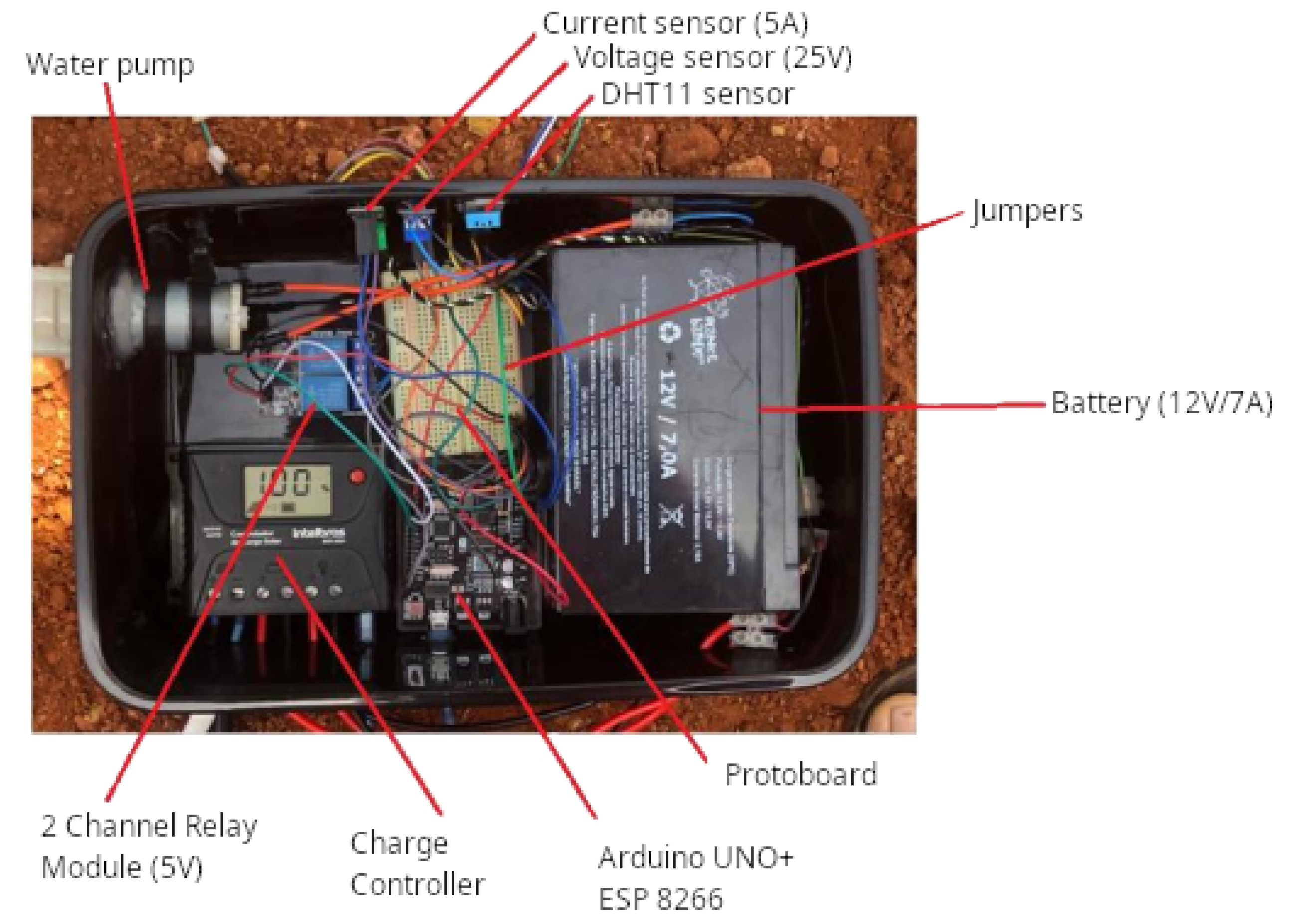
The prototype was developed and tested in the Electrotechnical Laboratory of the Agricultural and Environmental Engineering course at the Federal University of Rondonópolis (UFR), located in Brazil. The components that were used in the prototype are Arduino Uno R3, the ESP8266 development board, a resistive soil moisture sensor, a 25 V voltage sensor, the ACS712 5A current sensor, flow sensor model YF-S201, a humidity and temperature sensor—DHT11, 5 V relay module—with 2 channels, an 85 W poly R5A/D solar panel, PWM ECP 1024 Intelbras charge controller, and a water pump. Figure 1 and Figure 2 present the system assembly schematic and its practical assembly, respectively.
Firstly, the sensors used in the prototype were calibrated. The methodology proposed by [45,46,47] to calibrate the soil moisture sensor was used. Thus, 200 g of dry soil was weighed in a microwave oven with a precision analytical balance, as suggested in the [3]. Portions of water were also considered, which, when added to the soil sample, were equivalent to 9, 11, 13, 15, 17, 19, 21, 23, 25, 27, and 29% of moisture based on mass. The humidity range chosen for calibration was based on the average field capacity and permanent wilting point of the University’s experimental area. Thus, for the 9% moisture percentage, 18 g of water was added to the 200 g soil sample. Then, to raise the humidity to 11%, another 4 g of water was added to the model, and so on, to obtain the remaining percentages of soil moisture.
As the water was added to the soil sample, analogue readings from the humidity sensor were extracted, with a 10 min interval between each lesson, so the sensorwas stabilised [45]. Once this was completed, based on the points analogue reading of the sensor and percentage of soil moisture, the equation of the linear regression line was calculated in a spreadsheet, and later the equation was used in the programming carried out using the Arduino IDE.
An adjustable voltage source was used to calibrate the ACS712 5A current and 25 V voltage sensors, feeding a 60 W incandescent lamp representing the system load. In this way, the voltage source was adjusted to supply the load with 12, 14, 16, 18, 20, 22, and 24 V. The ACS712 5A current sensor was connected in series with the circuit, and subsequently, the 25 V voltage sensor was connected in parallel to take the readings. Using a digital multimeter, measurements of the current and voltage applied to the load were carried out. Subsequently, the sensor readings were adjusted according to the digital multimeter.
To calibrate the YF-S201 flow sensor, a constant proposed by [48] was used, which offers a calibration factor between the flow in (L/min) and the frequency in (Hz), with the proposed adjustment constant being equivalent to 4.5. Therefore, a container with 500 mL of water was used to carry out the test. The volume was subsequently passed through the sensor with the aid of the water pump, seeking to verify whether the constant entered in the programming would accurately read the volume of water passed through the sensor.
To begin using Adafruit IO, first, sign up for a free account. Then, configure feeds and dashboards. Feeds act as online variables, managing data exchange between servers and sensors. Create feeds for each system variable: soil humidity, air humidity, temperature, voltage, current, and water volume for irrigation. The dashboard, a customizable display panel, showcases sensor readings and data graphs. Customise the project dashboard to present sensor values and graphical data.
Although there are other IoT platforms, such as Arduino IoT Cloud and Blynk, the chosen platform was AdaFruit IO. This choice was made considereing the ease of connection, configuration, data volume, update rates, and widgets (devices) available.
Even though we have access to other sensors with greater sensitivity and precision, such as capacitive soil moisture sensors, the sensors used, including the resistive soil moisture sensor, were chosen due to their low cost and robustness, as we aimed to use sensors that could serve local agricultural projects in Brazil.
The system automation was carried out using the Arduino microcontroller together with ESP8266. In short, the connection between microcontrollers on the development board occurred via the ports that are used in the i2C communication of the Arduino UNO R3, namely SDA and SCL, and the GPIO 0 and 2 from ESP8266.
Using the a2A library, the microcontroller ESP8266 could perform the master function while the Arduino microcontroller worked as a slave. Notably, the i2C protocol was only used for sending and receiving information since, in other processes, microcontrollers worked independently.
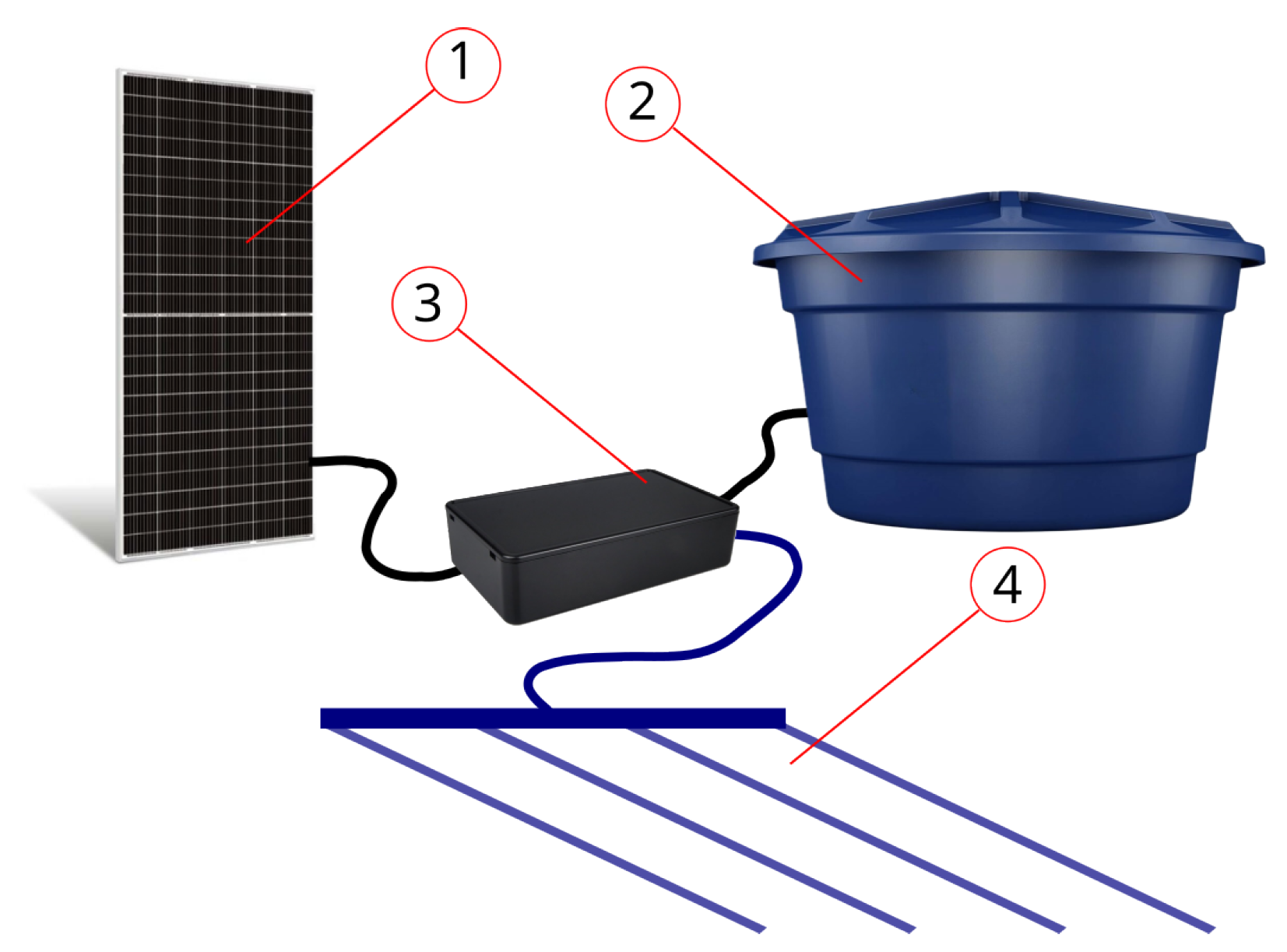
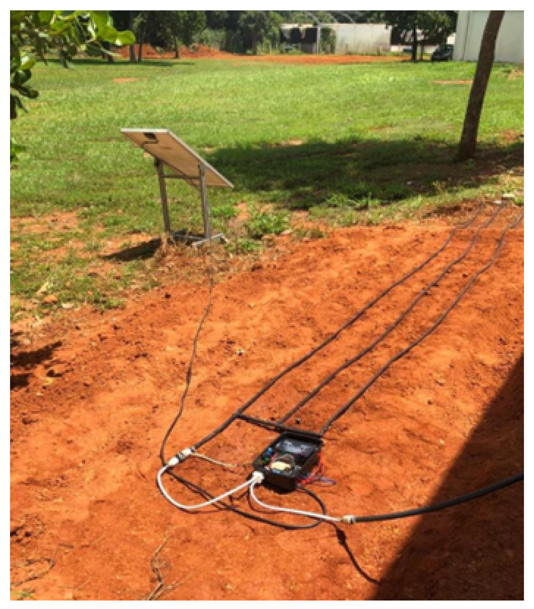
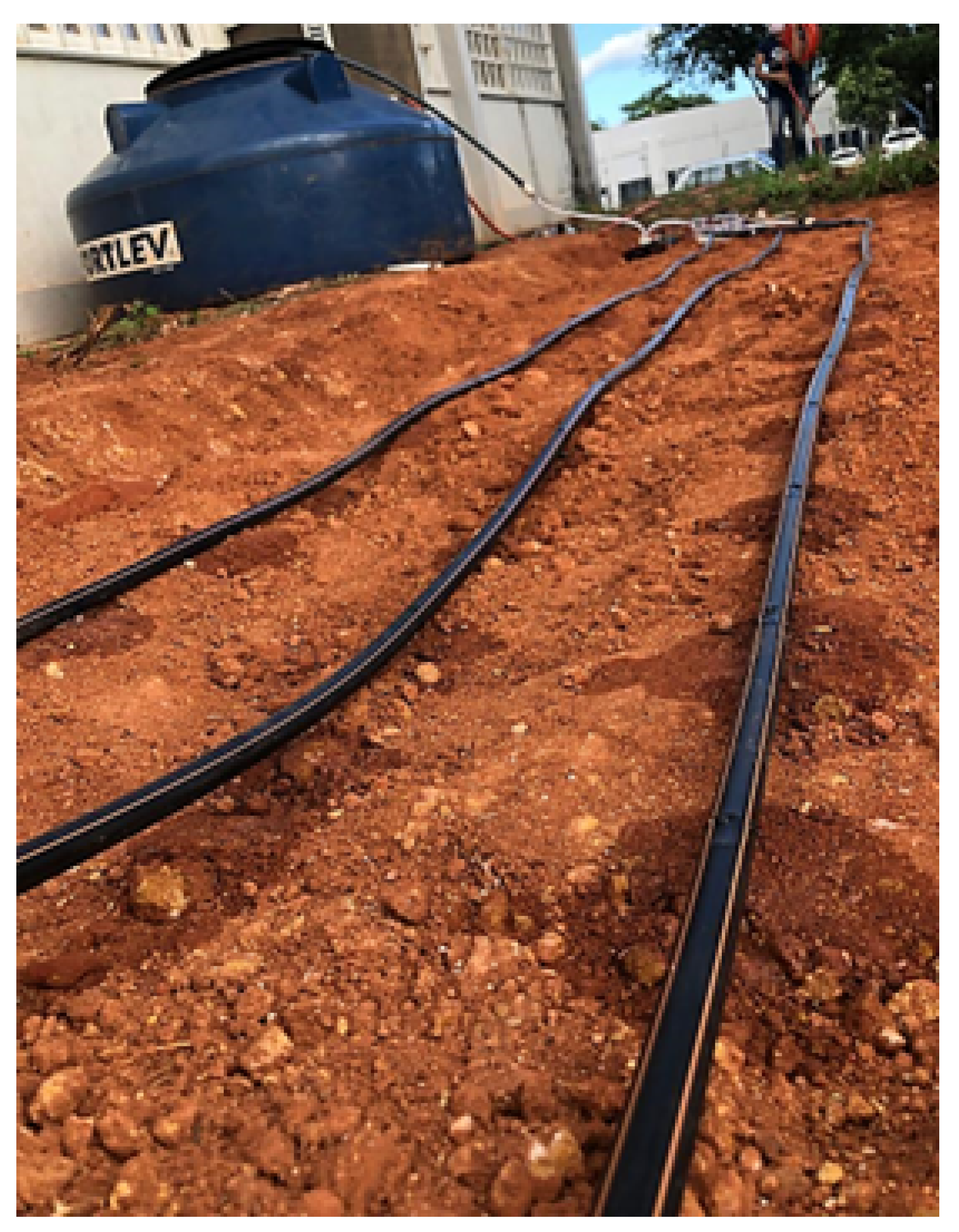
After assembly, the prototype was installed under real field conditions in the University’s experimental area. The irrigation system consisted of drip tapes, photovoltaic panels, and water reservoirs used for drip irrigation. After the initial tests, the system remained connected between 11 March 2022 and 15 March 2022, totalling 5 days of data collection. The arrangement of the system elements was carried out as shown in Figure 3, and the practical installation of the components was carried out as shown in Figure 4.

3. Results and Discussions

3.1. Resistive Humidity Sensor Calibration

According to the readings taken by the resistive soil moisture sensor presented in Table 1, the sensor that was used behaved as expected, reducing the analog tasks as the water was added to the sample to increase the humidity percentage.
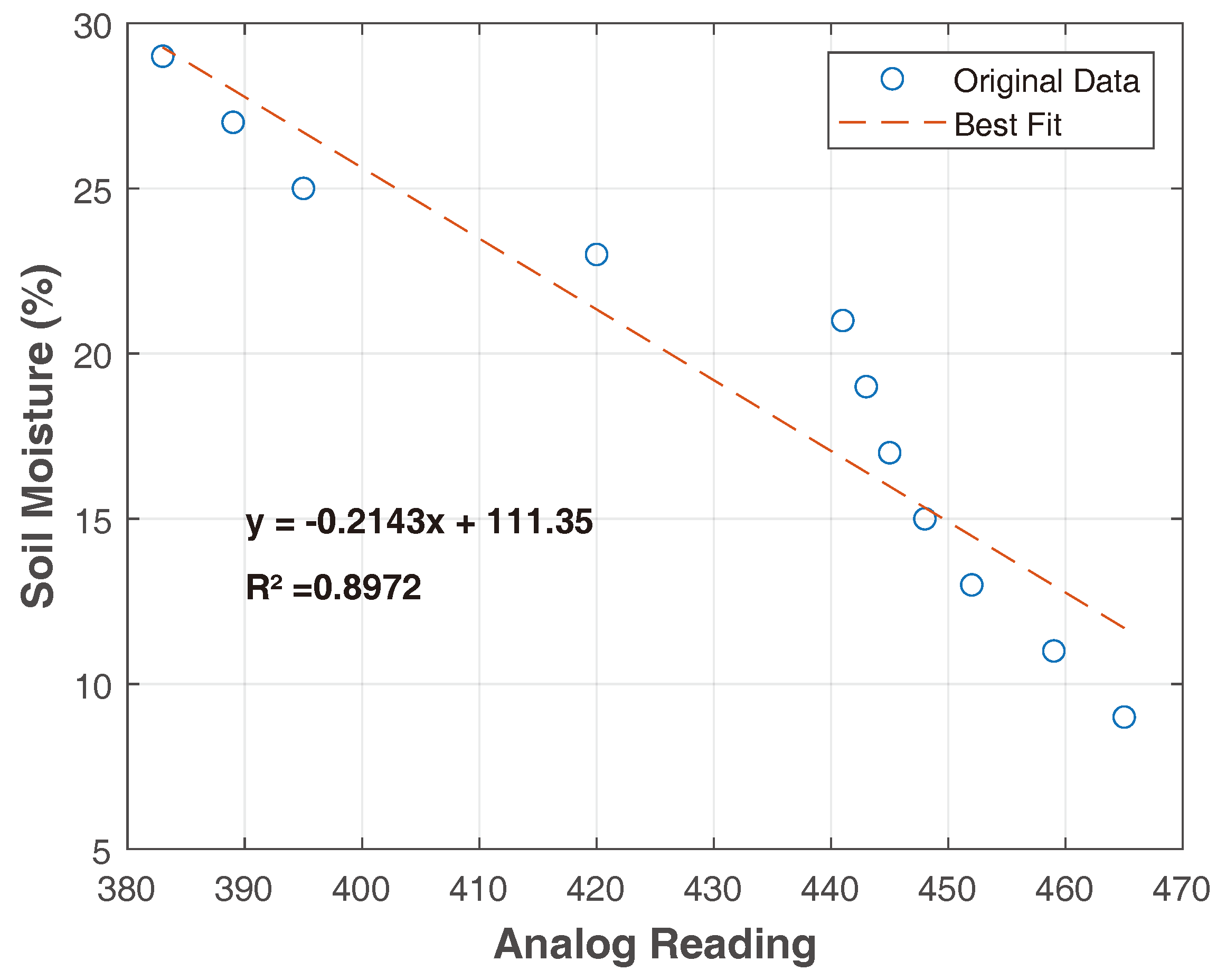
After extracting the readings, in an electronic spreadsheet, the equation of the linear regression line was calculated, as performed by [46], finding the equation and R 2 expressed in Figure 5.
It is known that the coefficient of determination R2 consists of an indicator that measures the quality of adjustment of a regression line. This varies between 0 and 1; thus, the higher the R2, the more explanatory the model is, and the better adapted to the sample [49]. Given this, according to Figure 5, the relationship between the sensor’s analog reading and soil moisture was adjusted to a linear model with R 2 of 0.8972; that is, the analog readings are capable of describing 89.72% of the model in question.
However, it is worth highlighting that the points that were found could be adapted to other regression models; however, due to the behaviour of the sensor, it was decided to generate only the linear regression curve, as per Pereira (2020).
In the calibration test developed by [50], which used HL69-resistive sensors in Red Oxisol, the relationship between the sensor’s analog reading and soil moisture was adjusted to a linear model with an R2 above 0, 97. In other studies developed by [46], with the resistive sensor, a coefficient of determination R2 of 93.9% was obtained using the linear regression model.
Thus, it is possible to observe that different behaviours occur for the different calibration tests and sensor models, and the behaviours may vary according to the type and texture of the soil, among other factors. Therefore, individual calibrations must be carried out for all sensors under the conditions in which they will be used [45,50,51,52].

3.2. Calibration of ACS712 5A Current Sensor and 25 V Voltage Sensor

When programming the ACS712 5A current sensor, aiming to increase the ease and reduce the number of necessary calculations, the ACS712-Arduino library was used to convert the sensor’s analogue readings into a present value in Ampere. We chose the library due to the sensor’s uniqueness and ability to perform current measurements at negative values.
In this way, by applying the “sensor.calibrate( )” function available from the library, it was possible to obtain a reading approximate to that of the digital multimeter. Thus, as shown in Table 2, for each voltage applied to the load, current readings from the sensor and digital multimeter were extracted for subsequent adjustment.
Table 2 does not showy large discrepancies when comparing the readings taken by the ACS712 5A current sensor with those of the digital multimeter. The average error found in readings regarding the voltage source was 2.21%; for the digital multimeter, it was 1.69%. Considering the multimeter as the calibration base, an average adjustment ratio of 0.97 was found.
The test was repeated to validate the values after obtaining and applying the adjustment relationship in the sensor’s programming. Thus, after extracting the readings from the digital multimeter and the current sensor, the values presented in Table 3 were found.
After entering the average calibration constant, an average error was found regarding the adjustable source of 0.58%, and an average error regarding the digital multimeter of 0.14% was found. In this way, using the adjustment ratio, it became possible to reduce the average error in the sensor readings regarding the digital multimeter by approximately 91%, thus making the readings more accurate.
When programming the 25 V voltage sensor, no library was used to relate the analogue readings taken by the sensor with the voltage readings taken with the digital multimeter. In this way, all measured readings were recorded, obtaining the data expressed in Table 4.
Thus, according to the data in Table 4, an average adjustment ratio of 0.024165522 converted the sensor’s analogue reading into a voltage value close to that measured by the digital multimeter. In this way, after applying the calibration constant, the process was repeated, obtaining the readings in Table 5. With the application of the calibration constant, it became possible to adjust the sensor readings of the multimeter, presenting an average error of 0.89945.

3.3. Adafruit IO Development Platform

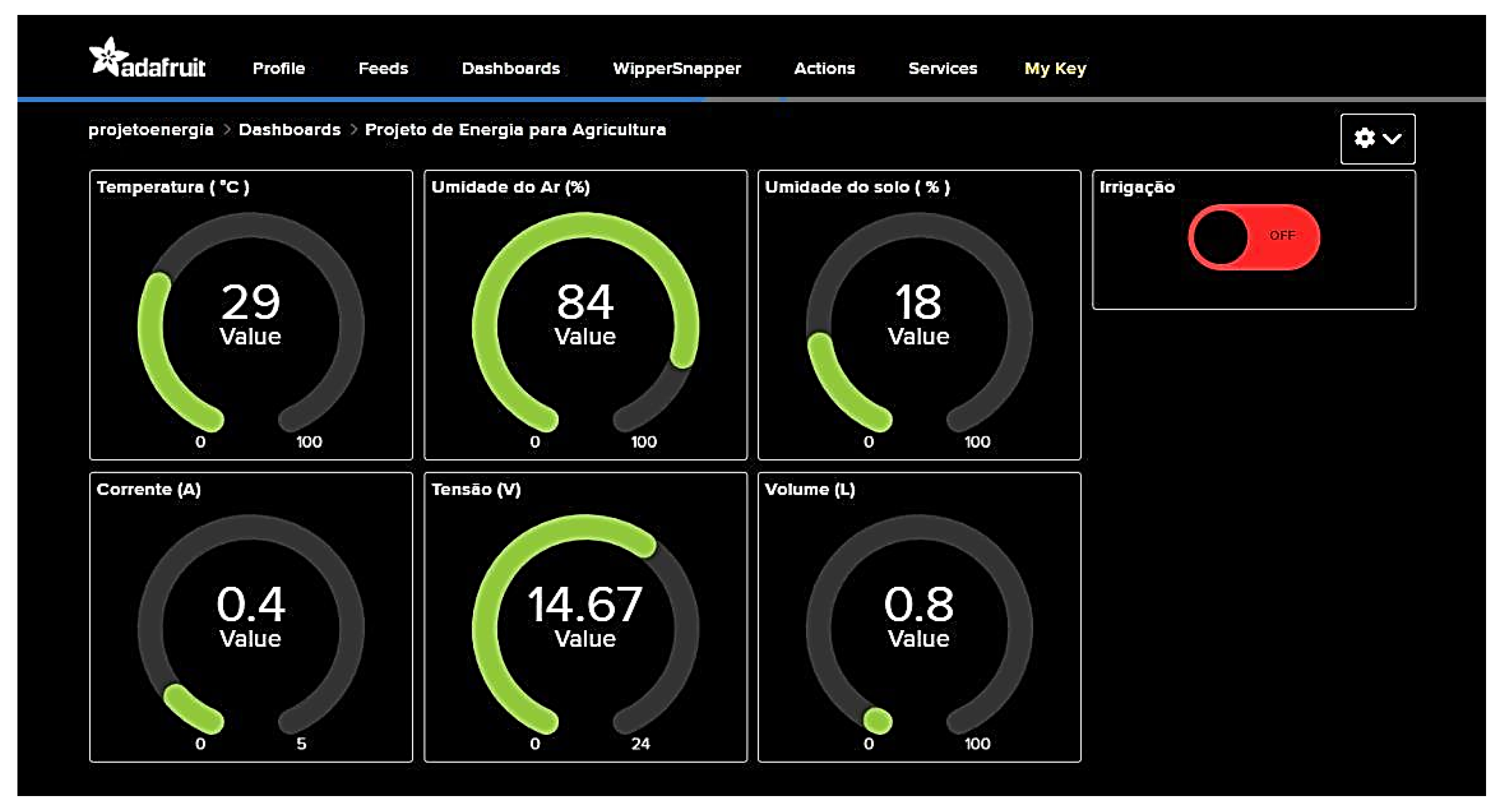
Tests carried out on the Adafruit IO platform proved convincing. Through the developed visualisation panel, illustrated in Figure 6, it was possible to monitor the readings measured by the sensors in real-time. There were no limitations regarding the received data. During the five days of practical testing, the platform quickly received sensor readings, displaying current, voltage, soil humidity, air humidity, temperature, and volume values on the dashboard.
Through the developed programming and the Adafruit portal, it was possible to control the irrigation system remotely. An irrigation button is displayed on the dashboard, illustrated in Figure 6. In the tests, it was possible to remotely turn on the system’s irrigation in real-time by activating the button. There were no restrictions regarding the activation distance, and it could occur from anywhere as long as you had access to the internet.
The ease of using remote control technology makes it possible to bring this tool into the daily lives of small producers or residential gardens. Its use allows for greater practicality and control over the system.
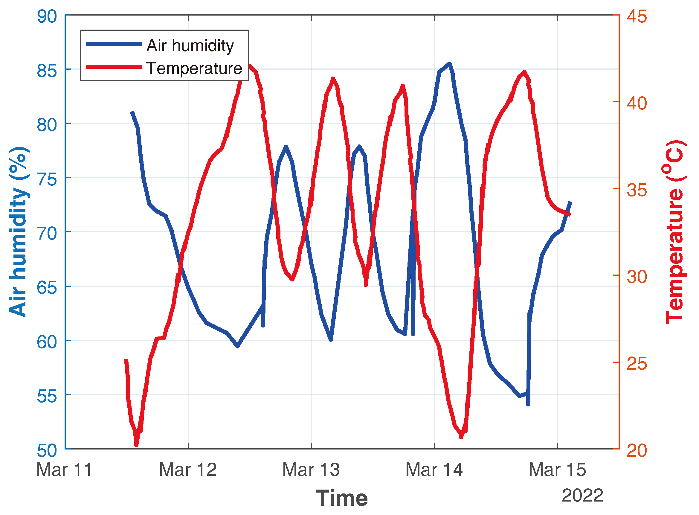
According to the information received, graphs were generated on the platform to monitor the variables’ behaviour, as shown in Figure 7, Figure 8, Figure 9, Figure 10 and Figure 11. These graphs are generated in real-time by the Adafruit platform. Therefore, the system operator does not have the necessary control to improve the presentation of the figures. They were added to illustrate the visualisation of the data provided by the platform. These data can be exported via “CSV” and graphically improved, as shown in Figure 12.
Figure 7 shows the monitoring of the system voltage, in which the system was energised until 08:56. After this time, the operator de-energised the system, using the platform’s remote control (red button) (Figure 6) to verify this functionality.
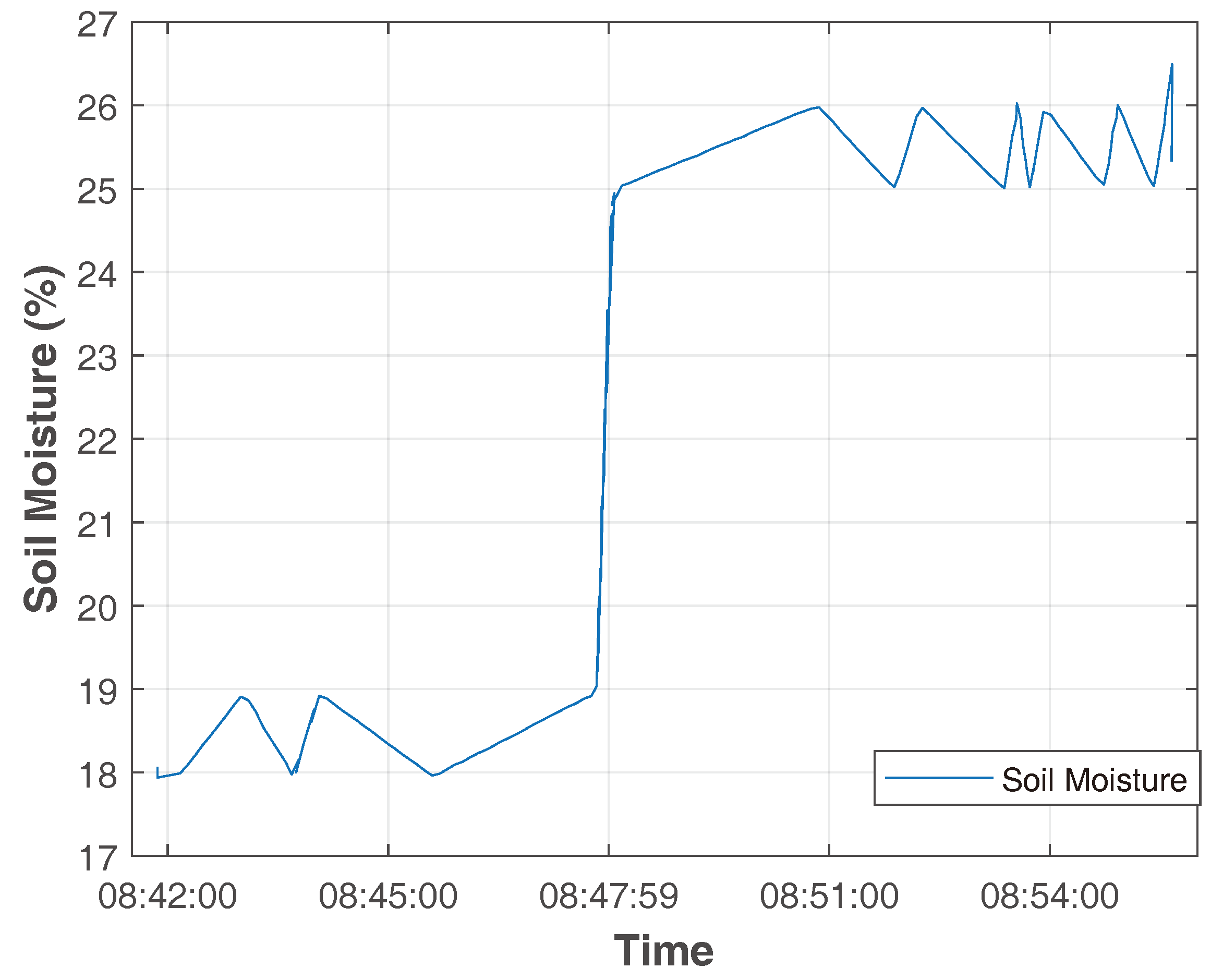
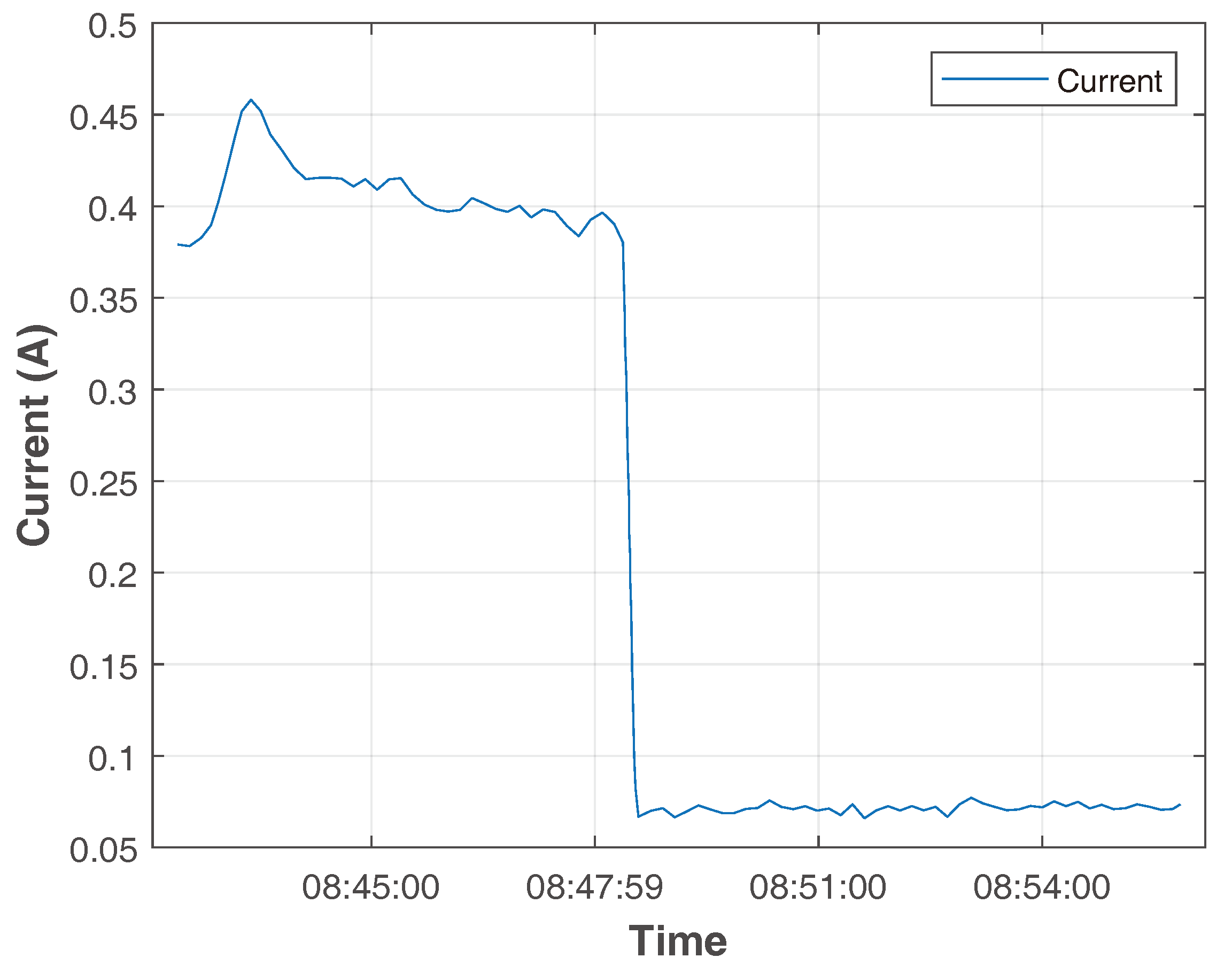
Figure 8 shows the monitoring of the soil moisture sensor. The sensor adjustment limits were set between 20 and 25% humidity. Thus, as soil moisture varied between 18 and 19% before 8:47 am, the irrigation system was activated, showing an electrical current value of around 0.4 A, as shown in Figure 9. With the activation of the irrigation system, it is possible to observe that the soil humidity exceeded the 25% limit, and after 08:47 am, the system was automatically turned off, as shown in Figure 9, presenting a record of the low electrical current value. Even when the system is turned off, a small amount of electrical current is observed due to the electrical supply to all equipment.
The system pumped the volume of water shown in Figure 10 during real-time monitoring through the flow sensor. As the irrigation system was activated before 8:47 am, the volume of pumped water increased during this period.
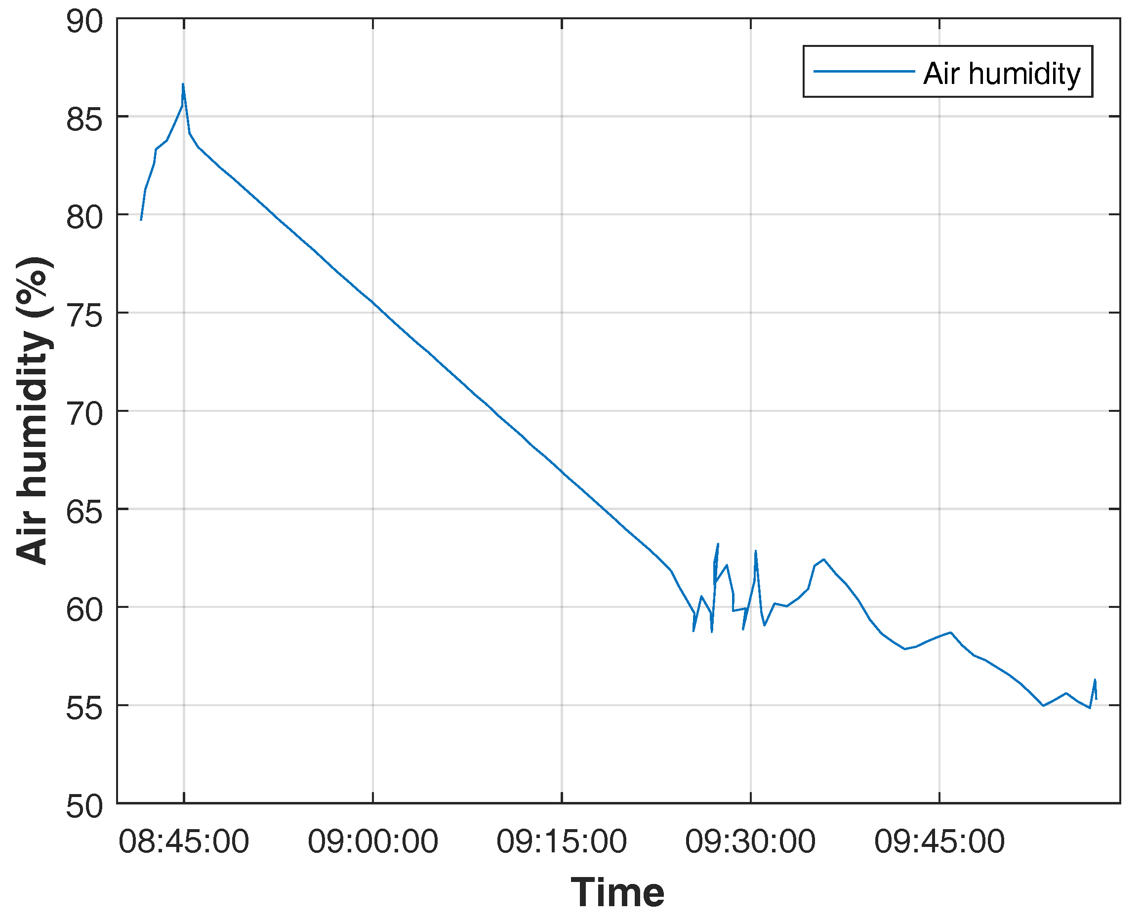
Figure 11 displays the reading of the air humidity sensor. We positioned this sensor close to the ground and activated the irrigation system in the early hours, before 8:47 am, which resulted in a higher sensor reading value of around 85%. As time passes and the irrigation system remains turned off, we observe a decrease in humidity.

3.4. Implementation of the Prototype in the Experimental Area

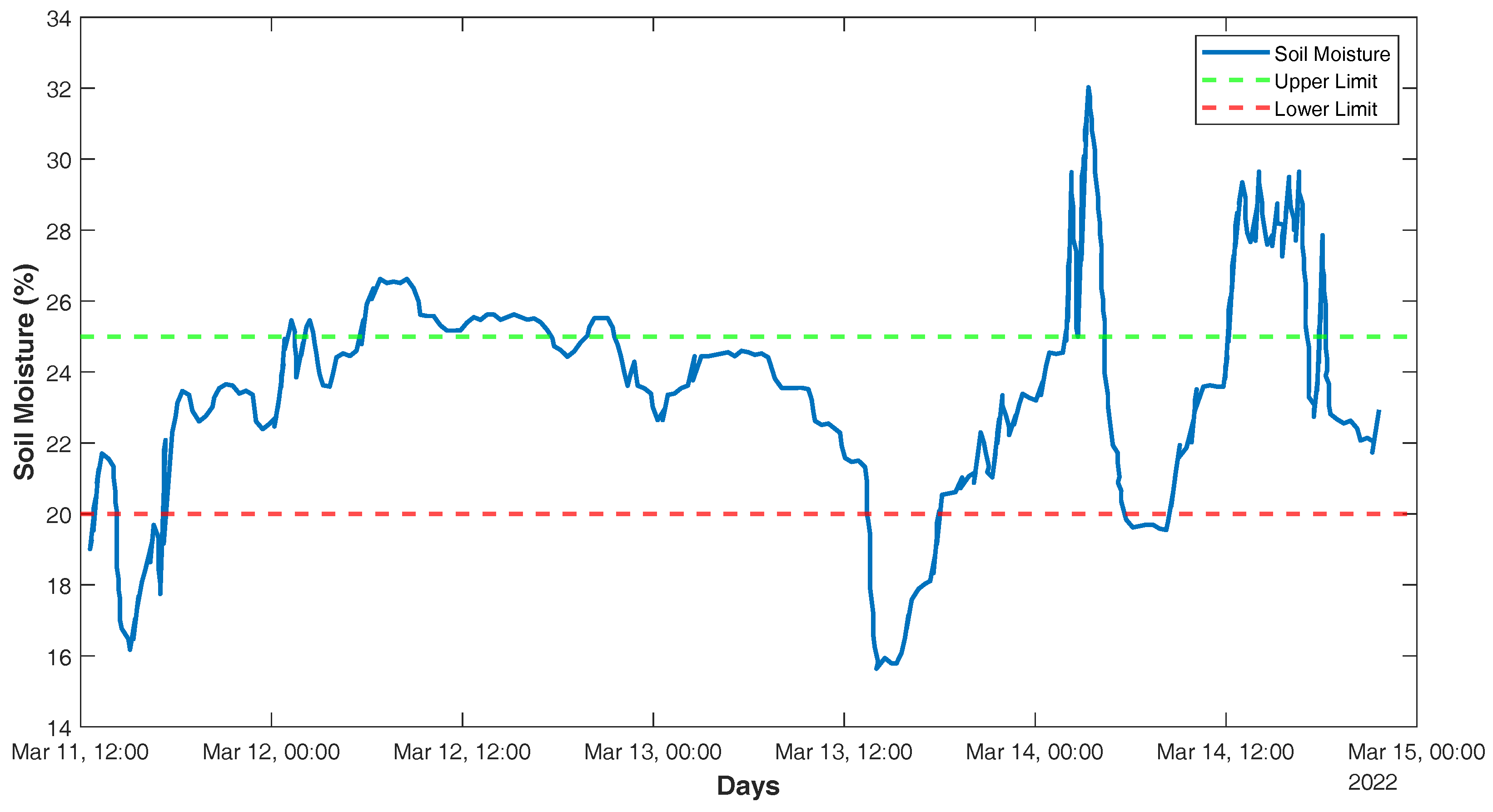
The test was carried out during the period between 11 March and 15 May 2022, totaling 5 days of monitoring. The automatic activation of the system was programmed according to soil moisture readings. Thus, it was stipulated that irrigation would occur when the soil moisture percentage was below 20% and would be deactivated when the moisture percentage was above 25%.
Thus, according to the “CSV” data extracted from the platform, it was possible to generate a graph of soil moisture throughout the days of the experiment, as shown in Figure 12. Figure 12 shows that, during the test days, the system was activated three times, with the activation days corresponding to 11, 13 and 14 March. It is observed that the sensor’s adjustment limits were the humidity sensor recordings, which were adjusted to between 20 and 25% humidity, recording higher and lower values. This is due to a delay in the platform receiving the sensor readings, allowing for longer and shorter irrigation times and, consequently, higher and lower humidities, without affecting the functioning of the prototype.
Figure 13 shows the moment when the irrigation system was activated. Figure 14 shows the moment the irrigation system was deactivated after reaching the maximum soil moisture, as previously defined in the programming.
From the volume readings taken by the flow sensor, the graph shown in Figure 15 was generated. During the five days of testing, 28.2 litres of water were consumed, intended for system irrigation. It is observed that, on days when soil humidity was below 20%, there were increases in the volume of water consumed, thus indicating the activation of the system during these periods.
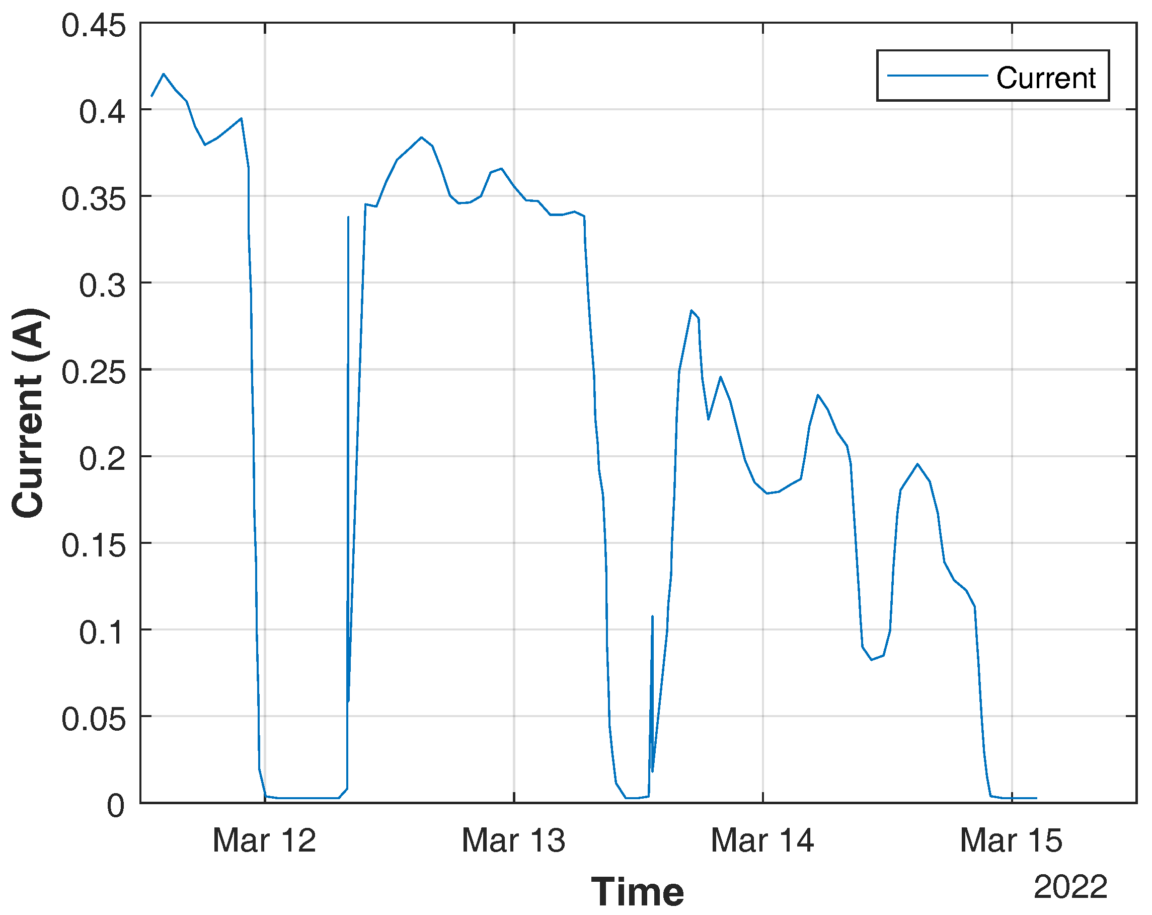
From the readings of the current and voltage sensors, graphs of current, voltage, power, and energy consumption were generated, presented in Figure 16, Figure 17, Figure 18 and Figure 19 respectively. In Figure 16, Figure 17 and Figure 18, the voltage, current, and power are shown to have zero values on days 12 and 14 due to the system shutdown caused by the soil moisture sensor after recording the pre-defined percentages when monitoring the moisture.
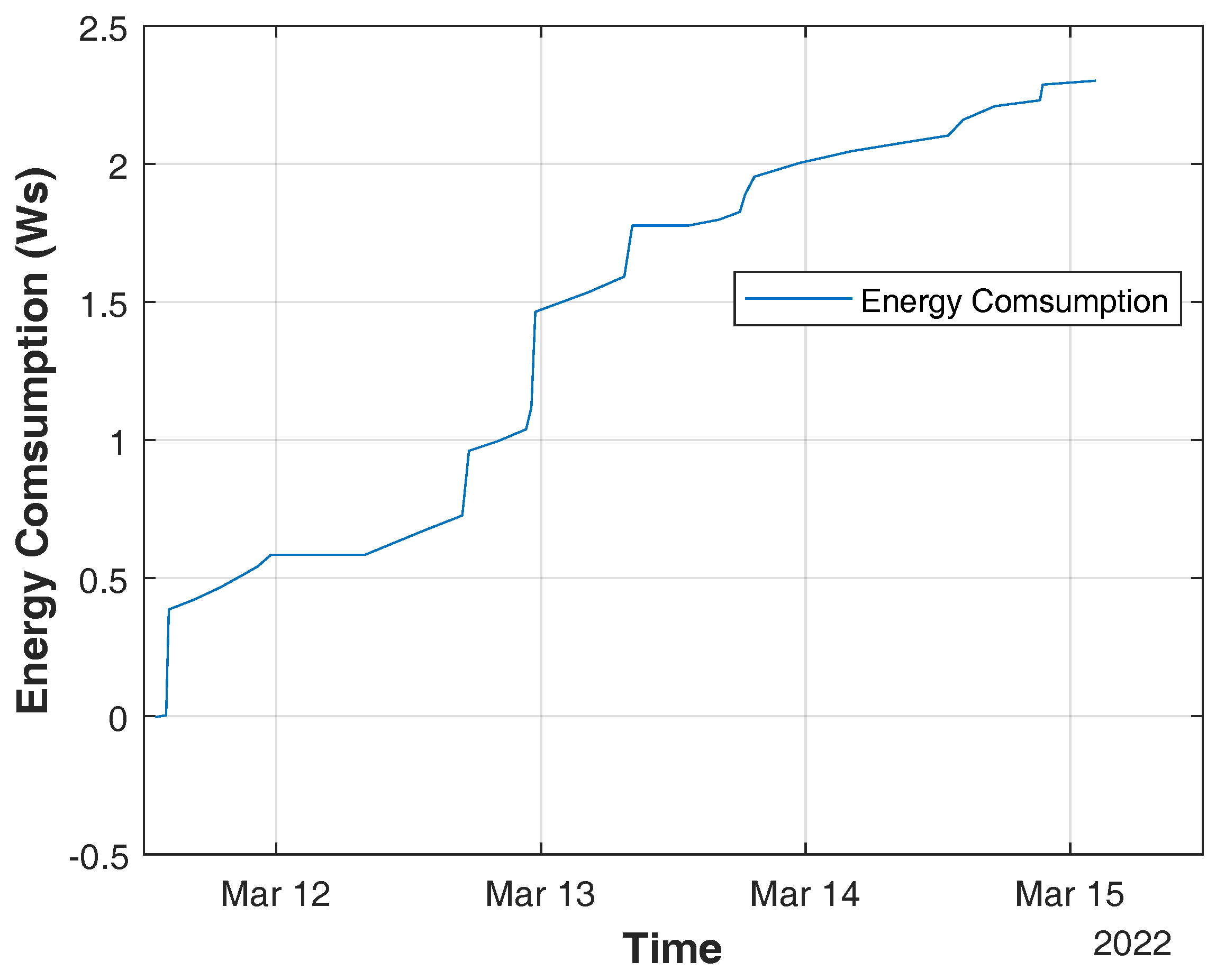
During the five days of testing, the energy consumption, calculated using an electronic spreadsheet, was equivalent to 2.3069 Ws, as shown in the graph in Figure 19. Considering the number of test days and the operating capacity of the pump used, it is concluded that the obtained value is consistent with the reality of the system. From the readings taken by the air temperature and humidity sensor—DHT 11—the graph expressed in Figure 20 was generated. It can be seen from the graph that the properties, air temperature, and humidity present inversely proportional behaviour. In other words, when the ambient temperature is high, air humidity decreases and vice versa.

4. Conclusions

The present work demonstrated that applying the Internet of Things concept in an automated irrigation system powered by photovoltaic energy, using humidity, current, voltage, flow, and temperature sensors, is possible. After tests were carried out with the prototype, it was possible to use IoT technology, which can be replicated and expanded as long as the necessary adaptations are made, facilitating better production control for the small producer.
Using the Adafruit IO platform makes it possible to visualise the analysed variables in the system in real-time. In addition to providing information monitoring on a smartphone or computer, the platform offers the means to exercise remote control of the system.
During the five days of testing, the system behaved as expected, activating irrigation according to the stipulated soil moisture. From the generated data, graphs can be developed to monitor all the analysed variables.
This work has great potential for future research as it is a prototype, long-term operation that requires needs validation in the field for prolonged periods, and the durability and degradation of the components over time need to be evaluated. It is possible to expand the project to other sensors, such as solar irradiation, to facilitate wireless data transmission between the sensors, and, finally, to use other communication protocols. Regarding the aspects related to implementation costs, a relationship was observed with commercial products with similar functions regarding the components used in this project; the cost ratio is 3 to 5 times lower.

Author Contributions

Conceptualisation, R.C.B. and C.H.B.; methodology, R.C.B. and C.H.B.; validation, R.C.B., C.H.B. and V.C.D.; formal analysis, R.C.B., C.H.B. and V.C.D.; investigation, R.C.B. and C.H.B.; resources, R.C.B., C.H.B. and M.E.C.B.; data curation, C.H.B. and V.C.D.; writing—original draft preparation, R.C.B., C.H.B. and V.C.D.; writing—review and editing, C.H.B. and M.E.C.B.; visualization, C.H.B. and M.E.C.B.; supervision, R.C.B. and C.H.B.; project administration, R.C.B.; funding acquisition, R.C.B. and C.H.B. All authors have read and agreed to the published version of the manuscript.

Funding

This research was funded by the Coordenação de Aperfeiçoamento de Pessoal de Nível Superior (CAPES) grant number #001 and Fundação de Amparo à Pesquisa do Estado do Mato Grosso (FAPEMAT).

Data Availability Statement

Data are contained within the article.

Conflicts of Interest

The authors declare no conflict of interest. The funders had no role in the design of the study; in the collection, analyses, or interpretation of data; in the writing of the manuscript; or in the decision to publish the results.

Abbreviations

The following abbreviations are used in this manuscript:
CSVComma Separated Values
GPIOGeneral Purpose Input/Output
i2CInter-Integrated Circuit
IOInput and Output
IoTInternet of Things
PWMPulse Width Modulation
SCLSerial Clock
SDASerial Data
UFRFederal University of Rondonópolis

References

  1. ONU. Perspectiva Global Reportagens Humanas. 2019. Available online: https://news.un.org/pt/story/2019/06/1676601 (accessed on 21 February 2022).
  2. Pawlak, K.; Kolodziejcczak, M. The Role of Agriculture in Ensuring Food Security in Developing Countries: Considerations in the Context of the Problem of Sustainable Food Production. Sustainability 2020, 12, 5488. [Google Scholar] [CrossRef]
  3. Embrapa. Determinação de matéria seca e umidade em solos e plantas com forno de microondas doméstico. In Circular Técnica, 33rd ed.; Embrapa: São Carlos, Brazil, 2002. [Google Scholar]
  4. Pardossi, A.; Incrocci, L.; Incrocci, G.; Malorgio, F.; Battista, P.; Bacci, L.; Rapi, B.; Marzialetti, P.; Hemming, J.; Balendonck, J. Root Zone Sensors for Irrigation Management in Intensive Agriculture. Sensors 2009, 9, 2809–2835. [Google Scholar] [CrossRef]
  5. da Cunha, K.C.B.; Da Rocha, R.V. Automação no processo de irrigação na agricultura familiar com plataforma Arduino. Rev. Eletrônica Competências Digit. Para Agric. Fam. 2015, 1, 62–74. [Google Scholar]
  6. Pinho, A.G.; Furtado, J.S.; Junior, J.A.; Ferreira, M.C.C.; AraúJo, S.D.F.A.; Albuquerque, R.D.N.O. Sistema de irrigação automatizado para uso em pequenas propriedades rurais. In Encontro Competências Digitais Para Agricultura Familiar; Tupã, Presidente Prudente, Belém, Anais eletrônicos; CoDAF: Tupã, Brazil, 2017; Volume 4, pp. 89–97. [Google Scholar]
  7. Cardoso, G.; de Sá, M.J.S.; da Silva, J.E.P.; Camargo, N. Plataforma arduino na automação da irrigação por gotejamento no cultivo da cana-deaçúcar. In Proceedings of the XXV CONIRD—Congresso Nacional de Irrigação e Drenagem, Ceres, Brazil, 8–13 November 2015. [Google Scholar]
  8. Silva, D.; Oliveira, G.; Silva, R.; Fernandes, C.; Jesus, L.D.; Begier, I. Controle automático da umidade do solo com energia solar para pequenos produtores. Embrapa Pantanal—Artigo em anais de congresso (ALICE). In Proceedings of the Simpósio Sobre Recursos Naturais e Socioeconômicos do Pantanal, Corumbá, Brazil, 17–20 July 2013. [Google Scholar]
  9. Singh, A.K.; Tariq, T.; Ahmer, M.F.; Sharma, G.; Bokoro, P.N.; Shongwe, T. Intelligent Control of Irrigation Systems Using Fuzzy Logic Controller. Energies 2022, 15, 7199. [Google Scholar] [CrossRef]
  10. Campos, M.S.; Alcantara, L.D.S. Sistema de bombeamento fotovoltaico para irrigação na agricultura familiar. Braz. J. Anim. Environ. Res. 2018, 1, 205–214. [Google Scholar]
  11. Izam, N.S.M.N.; Itam, Z.; Sing, W.L.; Syamsir, A. Sustainable Development Perspectives of Solar Energy Technologies with Focus on Solar Photovoltaic—A Review. Energies 2022, 15, 2790. [Google Scholar] [CrossRef]
  12. Pereira, H.M.P.; Mendes, L.F.R. Análise de rendimento do sistema de bombeamento de água por energia solar fotovoltaica para irrigação de um 87 viveiro de mudas. Rev. Vértices 2019, 21, 463–494. [Google Scholar] [CrossRef]
  13. Bento, M.E.C. Fixed Low-Order Wide-Area Damping Controller Considering Time Delays and Power System Operation Uncertainties. IEEE Trans. Power Syst. 2020, 35, 3918–3926. [Google Scholar] [CrossRef]
  14. Sarvi, M.; Azadian, A. A comprehensive review and classified comparison of MPPT algorithms in PV systems. Energy Syst. 2022, 13, 281–320. [Google Scholar] [CrossRef]
  15. Yap, K.Y.; Sarimuthu, C.R.; Lim, J.M.Y. Artificial Intelligence Based MPPT Techniques for Solar Power System: A review. J. Mod. Power Syst. Clean Energy 2020, 8, 1043–1059. [Google Scholar] [CrossRef]
  16. Bento, M.E.C. An approach for monitoring and updating the load margin of power systems in dynamic security assessment. Electr. Power Syst. Res. 2021, 198, 107365. [Google Scholar] [CrossRef]
  17. Bento, M.E.C. A method for monitoring the load margin of power systems under load growth variations. Sustain. Energy Grids Netw. 2022, 30, 100677. [Google Scholar] [CrossRef]
  18. Bento, M.E.C. Physics-Guided Neural Network for Load Margin Assessment of Power Systems. IEEE Trans. Power Syst. 2024, 39, 564–575. [Google Scholar] [CrossRef]
  19. Hetita, I.; Zalhaf, A.S.; Mansour, D.E.A.; Han, Y.; Yang, P.; Wang, C. Modeling and protection of photovoltaic systems during lightning strikes: A review. Renew. Energy 2022, 184, 134–148. [Google Scholar] [CrossRef]
  20. Manohar, M.; Koley, E.; Ghosh, S.; Mohanta, D.K.; Bansal, R.C. Spatio-temporal information based protection scheme for PV integrated microgrid under solar irradiance intermittency using deep convolutional neural network. Int. J. Electr. Power Energy Syst. 2020, 116, 105576. [Google Scholar] [CrossRef]
  21. Ola, S.R.; Saraswat, A.; Goyal, S.K.; Jhajharia, S.K.; Khan, B.; Mahela, O.P.; Alhelou, H.H.; Siano, P. A Protection Scheme for a Power System with Solar Energy Penetration. Appl. Sci. 2020, 10, 1516. [Google Scholar] [CrossRef]
  22. Adenle, A.A. Assessment of solar energy technologies in Africa-opportunities and challenges in meeting the 2030 agenda and sustainable development goals. Energy Policy 2020, 137, 111180. [Google Scholar] [CrossRef]
  23. Al-Dousari, A.; Al-Nassar, W.; Al-Hemoud, A.; Alsaleh, A.; Ramadan, A.; Al-Dousari, N.; Ahmed, M. Solar and wind energy: Challenges and solutions in desert regions. Energy 2019, 176, 184–194. [Google Scholar] [CrossRef]
  24. Bento, M.E.C. Monitoring of the power system load margin based on a machine learning technique. Electr. Eng. 2022, 104, 249–258. [Google Scholar] [CrossRef]
  25. Bento, M.E.C. Wide-Area Measurement-Based Two-Level Control Design to Tolerate Permanent Communication Failures. Energies 2023, 16, 5646. [Google Scholar] [CrossRef]
  26. Bento, M.E.C. Load Margin Assessment of Power Systems Using Physics-Informed Neural Network with Optimized Parameters. Energies 2024, 17, 1562. [Google Scholar] [CrossRef]
  27. Hancevic, P.I.; Nunez, H.M.; Rosellon, J. Distributed photovoltaic power generation: Possibilities, benefits, and challenges for a widespread application in the Mexican residential sector. Energy Policy 2017, 110, 478–489. [Google Scholar] [CrossRef]
  28. Barnham, K.; Knorr, K.; Mazzer, M. Benefits of photovoltaic power in supplying national electricity demand. Energy Policy 2013, 54, 385–390. [Google Scholar] [CrossRef]
  29. Al-Shahri, O.A.; Ismail, F.B.; Hannan, M.A.; Lipu, M.S.H.; Al-Shetwi, A.Q.; Begum, R.A.; Al-Muhsen, N.F.O.; Soujeri, E. Solar photovoltaic energy optimization methods, challenges and issues: A comprehensive review. J. Clean. Prod. 2021, 284, 125465. [Google Scholar] [CrossRef]
  30. Aman, M.M.; Solangi, K.H.; Hossain, M.S.; Badarudin, A.; Jasmon, G.B.; Mokhlis, H.; Bakar, A.H.A.; Kazi, S.N. A review of Safety, Health and Environmental (SHE) issues of solar energy system. Renew. Sustain. Energy Rev. 2015, 41, 1190–1204. [Google Scholar] [CrossRef]
  31. Bahadori, A.; Nwaoha, C. A review on solar energy utilisation in Australia. Renew. Sustain. Energy Rev. 2013, 18, 1–5. [Google Scholar] [CrossRef]
  32. Firjan. INDÚSTRIA 4.0: Internet das Coisas. Federação das Indústrias do Estado do Rio de Janeiro. 2016. Available online: https://www.firjan.com.br/lumis/portal (accessed on 18 May 2021).
  33. Revell, S. Internet of Things (IoT) and Machine to Machine Communications (M2M)—Challenges and Opportunities. 2013. Available online: https://connect.innovateuk.org/documents/3077922/3726367/ (accessed on 21 February 2022).
  34. Farooq, M.S.; Riaz, S.; Abid, A.; Umer, T.; Zikria, Y.B. Role of IoT Technology in Agriculture: A Systematic Literature Review. Electronics 2020, 9, 319. [Google Scholar] [CrossRef]
  35. Kim, W.S.; Lee, W.S.; Kim, Y.J. A Review of the Applications of the Internet of Things (IoT) for Agricultural Automation. J. Biosyst. Eng. 2020, 45, 385–400. [Google Scholar] [CrossRef]
  36. Xu, J.; Gu, B.; Tian, G. Review of agricultural IoT technology. Artif. Intell. Agric. 2022, 6, 10–22. [Google Scholar] [CrossRef]
  37. Watthanawisuth, N.; Tuantranont, A.; Kerdcharoen, T. Microclimate real-time monitoring based on ZigBee sensor network. In Proceedings of the SENSORS, 2009 IEEE, Christchurch, New Zealand, 25–28 October 2009; pp. 1814–1818. [Google Scholar] [CrossRef]
  38. Chen, K.-T.; Zhang, H.-H.; Wu, T.-T.; Hu, J.; Zhai, C.-Y.; Wang, D. Design of monitoring system for multilayer soil temperature and moisture based on WSN. In Proceedings of the 2014 International Conference on Wireless Communication and Sensor Network, Wuhan, China, 13–14 December 2014; pp. 425–430. [Google Scholar] [CrossRef]
  39. Postolache, O.; Pereira, J.D.; Girao, P.S. Wireless sensor network-based solution for environmental monitoring: Water quality assessment case study. IET Sci. Meas. Technol. 2014, 8, 610–616. [Google Scholar] [CrossRef]
  40. Langendoen, K.; Baggio, A.; Visser, O. Murphy loves potatoes: Experiences from a pilot sensor network deployment in precision agriculture. In Proceedings of the 20th IEEE International Parallel & Distributed Processing Symposium, Rhodes, Greece, 25–29 April 2006; pp. 1–8. [Google Scholar] [CrossRef]
  41. Khandani, S.K.; Kalantari, M. Using field data to design a sensor network. In Proceedings of the 2009 43rd Annual Conference on Information Sciences and Systems, Baltimore, MD, USA, 18–20 March 2009; pp. 219–223. [Google Scholar] [CrossRef]
  42. Lee, J.; Kang, H.; Bang, H.; Kang, S. Dynamic crop field analysis using mobile sensor node. In Proceedings of the 2012 International Conference on ICT Convergence (ICTC), Jeju, Republic of Korea, 15–17 October 2012; pp. 7–11. [Google Scholar] [CrossRef]
  43. Alahi, M.E.E.; Xie, L.; Mukhopadhyay, S.; Burkitt, L. A Temperature Compensated Smart Nitrate-Sensor for Agricultural Industry. IEEE Trans. Ind. Electron. 2017, 64, 7333–7341. [Google Scholar] [CrossRef]
  44. Krishna, K.L.; Silver, O.; Malende, W.F.; Anuradha, K. Internet of Things application for implementation of smart agriculture system. In Proceedings of the 2017 International Conference on I-SMAC (IoT in Social, Mobile, Analytics and Cloud) (I-SMAC), Palladam, India, 10–11 February 2017; pp. 54–59. [Google Scholar] [CrossRef]
  45. Oliveira, C.D.L. Calibração de Sensores de Umidade do Solo de Baixo Custo. Bachelor’s Thesis, Universidade Federal Rural de Pernambuco, Garanhuns, Brazil, 2018. [Google Scholar]
  46. Pereira, A.G. Sistema de Irrigação Automatizado Utilizando o Conceito de IOT Para Tomada de Decisão. Bachelor’s Thesis, UNESC, Criciúma, Brazil, 2020; p. 77. [Google Scholar]
  47. Dourado, V.C.; Ferreira, M.S.S.; Borges, R.C.; Beuter, C.H.; Silveira, M.H.D. Calibração de sensores de umidade resistivos HL-69 para uso no sistema automático de irrigação alimentado por energia solar. In Proceedings of the L Congresso Brasileiro de Engenharia Agrícola—CONBEA 2021, Online, 8–10 November 2021; Available online: https://conbea.org.br/anais/publicacoes/conbea-2021/livros-2021/energia-na-agricultura-eag-3/3053-calibracao-de-sensores-de-umidade-resistivos-hl-69-para-uso-no-sistema-automatico-de-irrigacao-alimentado-por-energia-solar/file (accessed on 29 March 2024).
  48. Castro, G.D. Usando o Sensor de Fluxo de áGua. ROBOCORE. 2020. Available online: https://tecnoblog.net/responde/referencia-site-abnt-artigos/ (accessed on 25 April 2022).
  49. Martins, E.G.M. Coeficiente de determinação. Rev. Ciência Elem. 2018, 6, 24. [Google Scholar]
  50. Gomes, F.H.F.; Cunha, F.N.; Lopes Filho, L.C.; Vidal, V.M.; Soares, F.A.L.; Teixeira, M.B. Calibração de um sensor de umidade do solo de baixo custo. Rev. Bras. Agric. Irrig. 2017, 11, 1509. [Google Scholar] [CrossRef]
  51. Gava, R.; da Silva, E.E.; Baio, F.H.R. Calibração de sensor eletrônico de umidade em diferentes texturas de solo. Rev. Bras. Eng. Biossistemas 2016, 10, 154–162. [Google Scholar]
  52. Leão, D.V.F.; Filho, G.S.T.; Freitas, D.L.A.; Oliveira, C.W.; Matias, S.S.R.; Barros, B.A.A. Avaliação e calibração de sensores de monitoramento da umidade superficial do solo/Evaluation and calibration of sensors for monitoring soil surface moisture. Braz. J. Dev. 2021, 7, 26294–26305. [Google Scholar] [CrossRef]
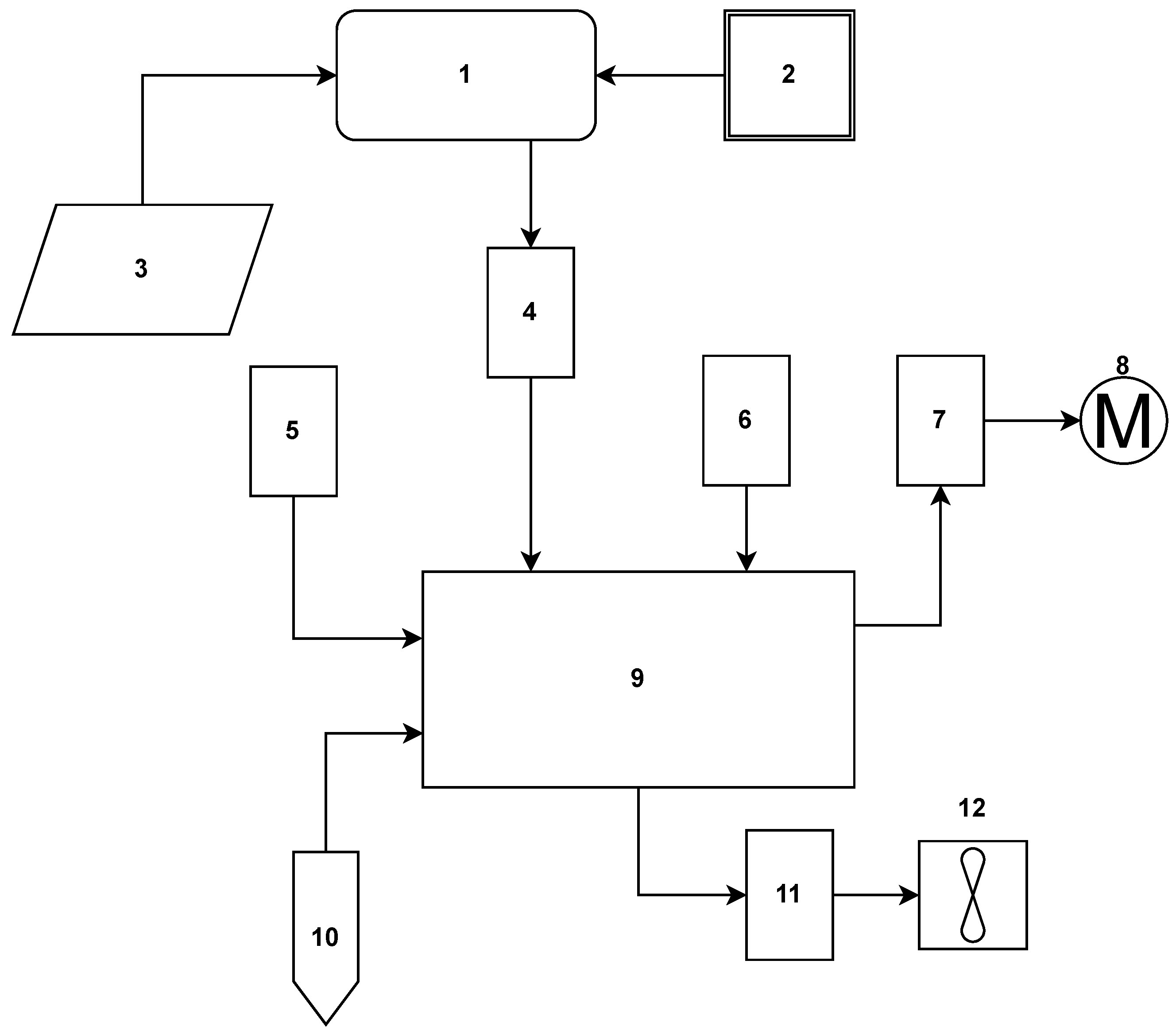
Figure 1. Automated, solar-powered irrigation prototype connections. (1) PWM ECP 1024 Intelbras charge controller; (2) battery; (3) 85 W poly R5A/D solar panel; (4) 25 V voltage sensor, ACS712 5A current sensor; (5) humidity and temperature sensor—DHT11; (6) ESP8266 development board; (7) 5 V relay module—two channels; (8) motor pump; (9) Arduino Uno R3; (10) resistive soil moisture sensor; (11) 5 V relay module—two channels; (12) flow sensor model YF-S201.
Energies 17 02219 g001
Figure 2. Practical assembly of the irrigation prototype.
Energies 17 02219 g002
Figure 3. Simplified arrangement of irrigation system components, consisting of (1) photovoltaic panels, (2) water reservoirs, (3) the assembled prototype, and (4) drip tapes.
Energies 17 02219 g003
Figure 4. Practical installation of the prototype and irrigation system.
Energies 17 02219 g004
Figure 5. Calibration of the HL-69-resistive soil moisture sensor.
Energies 17 02219 g005
Figure 6. Visualisation of readings taken by sensors through the dashboard developed on the Adafruit IO platform.
Energies 17 02219 g006
Figure 7. Graph monitoring voltage readings.
Energies 17 02219 g007
Figure 8. Chart tracking soil moisture readings.
Energies 17 02219 g008
Figure 9. Chart monitoring current readings.
Energies 17 02219 g009
Figure 10. Graph for monitoring water volume.
Energies 17 02219 g010
Figure 11. Graph for monitoring air humidity readings.
Energies 17 02219 g011
Figure 12. Soil moisture readings taken by the moisture sensor.
Energies 17 02219 g012
Figure 13. Activation of the irrigation system installed in the experimental area.
Energies 17 02219 g013
Figure 14. Irrigated area after turning off the irrigation system.
Energies 17 02219 g014
Figure 15. Total volume pumped over the days.
Energies 17 02219 g015
Figure 16. Readings taken by the ACS712 5th current sensor.
Energies 17 02219 g016
Figure 17. Readings taken by the 25 V voltage sensor.
Energies 17 02219 g017
Figure 18. Power calculation using voltage and current readings.
Energies 17 02219 g018
Figure 19. Energy consumption during the five test days.
Energies 17 02219 g019
Figure 20. Air temperature and humidity readings—DHT 11.
Energies 17 02219 g020
Table 1. Relationship between the percentage of soil moisture and the readings of the HL-69-resistive humidity sensor.
ReadingResistive Humidity Sensor
Analog ReadingSoil Moisture
4659%
45911%
45213%
44815%
44517%
44319%
44121%
42023%
39525%
10°38927%
11°38329%
Table 2. Readings taken by the ACS712 5A current sensor and digital multimeter.
Voltage Current Current Current
Applied (V) Source (A) Multimeter (A) Sensor (A)
121.581.581.59
141.691.691.74
161.821.811.86
181.951.941.99
202.062.062.10
222.172.162.21
242.292.282.33
Table 3. ACS 712 5A current sensor and digital multimeter readings after applying the calibration constant.
Voltage Current Current Current
Applied (V) Source (A) Multimeter (A) Sensor (A)
121.571.561.57
141.711.701.70
161.841.831.83
181.961.951.95
202.082.072.06
222.192.192.18
242.302.292.28
Table 4. Analog readings of the 25 V voltage sensor and digital multimeter voltage.
Voltage Voltage Voltage Analog
Applied (V) Source (V) Multimeter (V) Sensor
121211.88496
141413.84578
161615.80660
181817.76743
202019.98835
222221.70909
242423.70995
Table 5. The 25 V voltage sensor readings after applying the calibration constant.
Voltage Voltage Voltage Analog
Applied (V) Source (V) Multimeter (V) Sensor
121211.8011.88
141413.8313.96
161615.8515.99
181817.7717.95
202019.7719.96
222221.8021.90
242423.7024.00
Disclaimer/Publisher’s Note: The statements, opinions and data contained in all publications are solely those of the individual author(s) and contributor(s) and not of MDPI and/or the editor(s). MDPI and/or the editor(s) disclaim responsibility for any injury to people or property resulting from any ideas, methods, instructions or products referred to in the content.