1. Introduction
One of the biggest challenges, and simultaneously one of the biggest opportunities, in this era is in the area of energy and sustainability, and the transportation sector is sitting at the heart of it. Our current transportation sector is heavily dependent on fossil fuels. Nearly 88% of roughly 1.5 billion vehicles run on fossil fuels worldwide. The transport sector alone contributes significantly to global greenhouse gas (GHG) emissions [
1], accounting for 21.6% of total anthropogenic emissions. Road transport is a significant contributor to this sector, responsible for 77.9% of the total CO
2 emissions associated with transportation. Supposing we want to move towards achieving net-zero emissions, powertrain electrification must be prioritized since electric vehicles (EVs) have been at the forefront of reducing GHG emissions in the current decade. Even if EVs consume electricity from fossil fuels, they are a better alternative to fossil fuel-fed vehicles because the carbon from power plant exhaust is more accessible for capture than carbon from the tailpipe of vehicles.
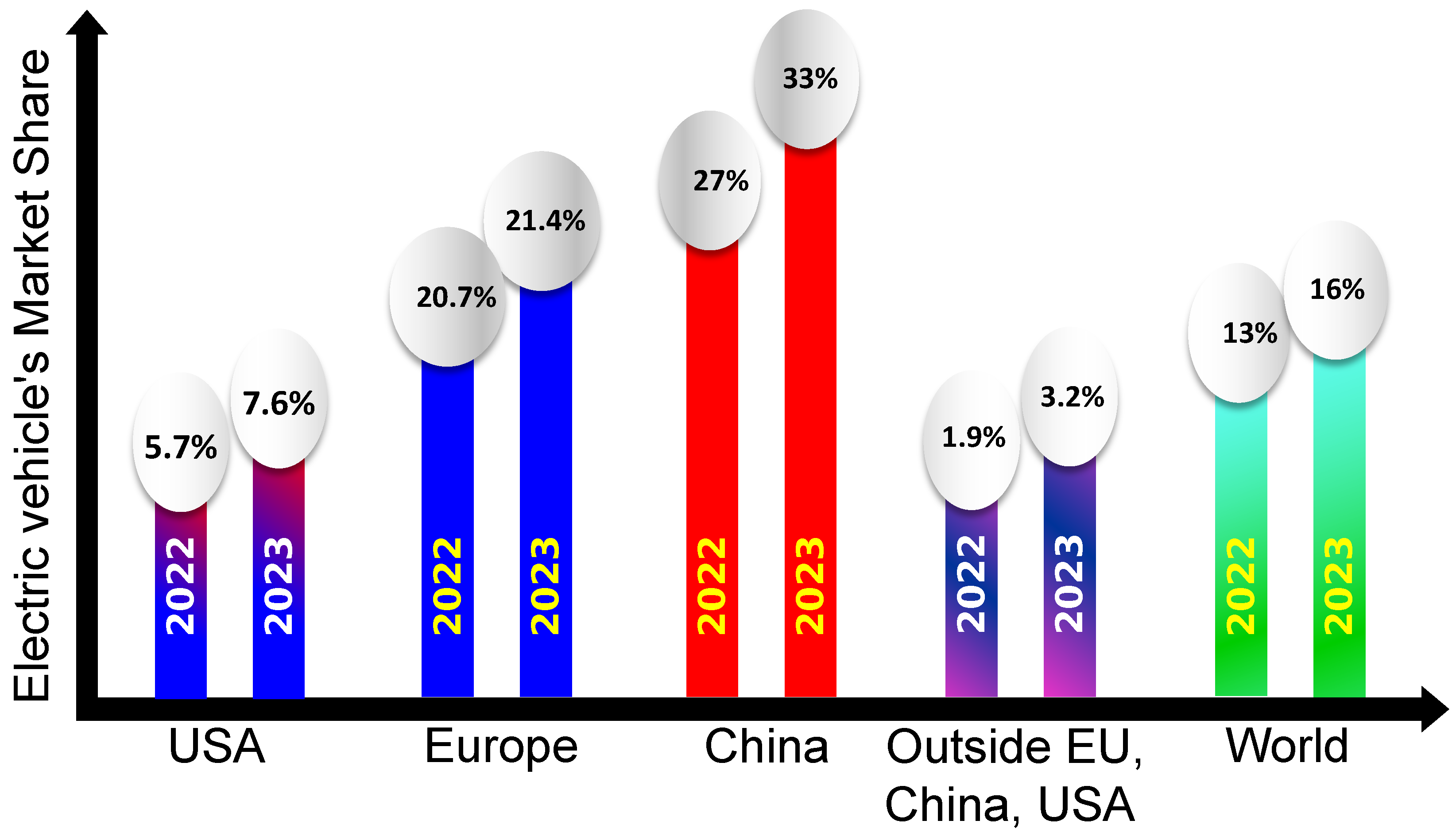
While the automotive industry is navigating towards electrification, recent trends suggest that EV sales have faced headwinds in some regions despite the enthusiasm for a green future. It is not being said that EV sales are not growing, but rather they are growing at a slower rate than expected, especially in the United States, as shown in
Figure 1 [
2,
3].
Figure 1 depicts the recent trend in EV adoption rate in the primary EV markets and across the world.
Recent trends suggest a slow adoption of EVs even though the battery costs and average EV costs are declining [
2,
4] due to research and development on multiple fronts, including but not limited to artificial intelligence (AI)- and machine learning (ML)-based optimal battery material finding and battery design [
5], AI- and ML-based optimal powertrain configuration design and sizing [
6,
7], and cost-effective and digitalized vehicle development programs for EVs [
8]. Three primary factors contribute to this slow adoption rate and apathy towards EVs:
Limited all-electric range and reduced energy efficiency of electric powertrains;
Deterioration of battery SOH before promised years of operation;
Lack of widespread and reliable charging infrastructure.
Several studies that have been conducted to identify the root cause of the first two factors reveal that existing and prospective EV buyers find that their EV’s battery reaches its end-of-life (EOL) long before what was promised to them. Similarly, EV users find discrepancies between the promised and actual all-electric ranges in real-world driving. It has been largely proven that many real-world factors, such as trip distance, ambient temperature, charging level, and driving behavior, affect the energy efficiency of the powertrain, resulting in discrepancies between the all-electric driving range promised by the original equipment manufacturers (OEMs) and real-world driving range [
9]. Similarly, deviations between real-world battery EOL and promised EOL are inevitable due to many real-world and user-related factors, such as driving patterns, temperature, types of charging, and the energy management controller of the EV [
10]. Typically, large-capacity EV batteries reach their EOL when their maximum capacity in terms of Ampere-hours (Ah) falls below 80–70% of their initial capacity [
11]. In contrast, smaller-capacity batteries reach their EOL when their maximum available power falls below 80% of their initial maximum power [
11].
Since there is an inevitable gap between EV testing conditions based on which the OEMs obtain their sticker values and government certifications and real-world EV operating conditions, and since the repercussions due to such gaps in terms of deterioration of energy efficiency and battery SOH cannot be alleviated with hardware-based improvements, software-level interventions in the VCU, especially in the energy management system (EMS), have been prioritized in both industry and academia. Unlike the EMSs for hybrid electric vehicles (HEVs) or fuel-cell electric vehicles (FCEVs), the EMSs for EVs do not have the flexibility of delegating a portion of the tractive power requested to onboard power sources other than the battery. Consequently, they must ask the battery for whatever power the driver requests. Hence, the EMSs for EVs should be designed intelligently to avoid using the battery abusively, improving energy efficiency and battery SOH.
Due to such constraints of the EMSs of EVs, a few indirect approaches are prescribed in the literature. Among various possible avenues, one involves implementing an intelligent battery management system (BMS) to oversee and regulate the SOH degradation of every battery cell within the pack [
12]. This approach maintains uniform capacity fading across all cells and prevents abnormal increases in capacity loss within any specific cell. Other strategies, such as charging and auxiliary power management, also allow for reduced charging times and an extended battery life cycle [
13]. However, these two approaches need to take the aspect of real-world driving into account when designing an intelligent EMS-based VCU. Therefore, the authors of this article have shifted their focus to leveraging vehicle-to-vehicle (V2V) communications during real-world driving to incorporate an intelligent feature into the VCU through which the VCU can reduce the battery’s SOH degradation and powertrain energy consumption. This feature is also quite well-known as an eco-driving feature, where the vehicles’ speed trajectory is optimized given that there are other constraints such as maintaining a safe distance between vehicles, adhering to signals at intersections and speed limits of the road, and respecting the feasible limits of the powertrain components [
14]. Moreover, this approach aligns with the contemporary automotive trend, emphasizing connected and autonomous vehicle technologies, specifically targeting enhanced energy efficiency and prolonged battery life. In recent years, the potential of connected and autonomous vehicles has grown significantly due to current technologies, enabling vehicle efficiency improvements [
15,
16] while maintaining high safety standards [
17]. Connectivity is pivotal in enhancing vehicles’ awareness of their surroundings and robustness in predicting external actions [
18]. These improvements are crucial for improving vehicle performance in challenging conditions where sensors face limitations [
19].
Literature Review
A few research works are presented in the literature on potential methods to leverage V2V communication in improving energy efficiency and reducing battery SOH degradation. The authors in [
20] corroborated that an EV’s energy consumption can be minimized at signalized intersections in city driving conditions if their speed profiles can be optimally controlled with an MPC framework, which exploits vehicle-to-infrastructure (V2I) communication, in comparison to manual, uninformed driving. However, this work did not exploit V2V communication and did not consider battery SOH degradation or maintaining a safe distance from the leading vehicle. An adaptive cruise control framework is presented in [
21] to exploit V2V communication to maintain a constant distance between the Ego and the Leading vehicle but overlooking the optimal energy consumption of the Ego vehicle. The frameworks in the above-mentioned articles are designed for a fixed driving scenario, making them non-adaptive to varying driving scenarios. The optimizer governs the adaptability of the eco-driving feature, and neither dynamic programming nor Pontryagin’s minimum principle-based optimizers can facilitate adaptability [
22,
23]. Reinforcement learning (RL)-based optimizers are widely accredited for their adaptability [
24] to different driving conditions, and authors in [
14,
25] presented adaptive cruise control with eco-driving features for EVs to improve energy efficiency and ensure safe following distance.
Nevertheless, RL-based methods have the intrinsic drawback of substantial training and safety conformity [
26]. Moreover, model-based RL approaches [
14,
25] need to learn the model of the traffic dynamics before prescribing optimal eco-driving control. An alternative solution, a data-driven predictive control, eliminates the need to learn a traffic dynamics model by leveraging historical data to inform control decisions [
27]. While similar to RL-based eco-driving control in its adaptability to varying driving scenarios, it necessitates a significant volume of data for accurate predictions.
Both linear [
28] and non-linear [
29] MPC frameworks have been proven to be suitable for real-time implementation of eco-driving-inspired adaptive cruise controls in NI real-time hardware [
28] and dSpace MicroAutobox 1401 [
29], respectively, and validating their battery life saving and energy saving capabilities, respectively. The efficacy of such eco-driving features and adaptive cruise control critically hinges upon the latency of V2V communication, which often hinders their real-world implementation. One approach to counter this issue is preparing a robust MPC framework against stochastic communication delays [
30].
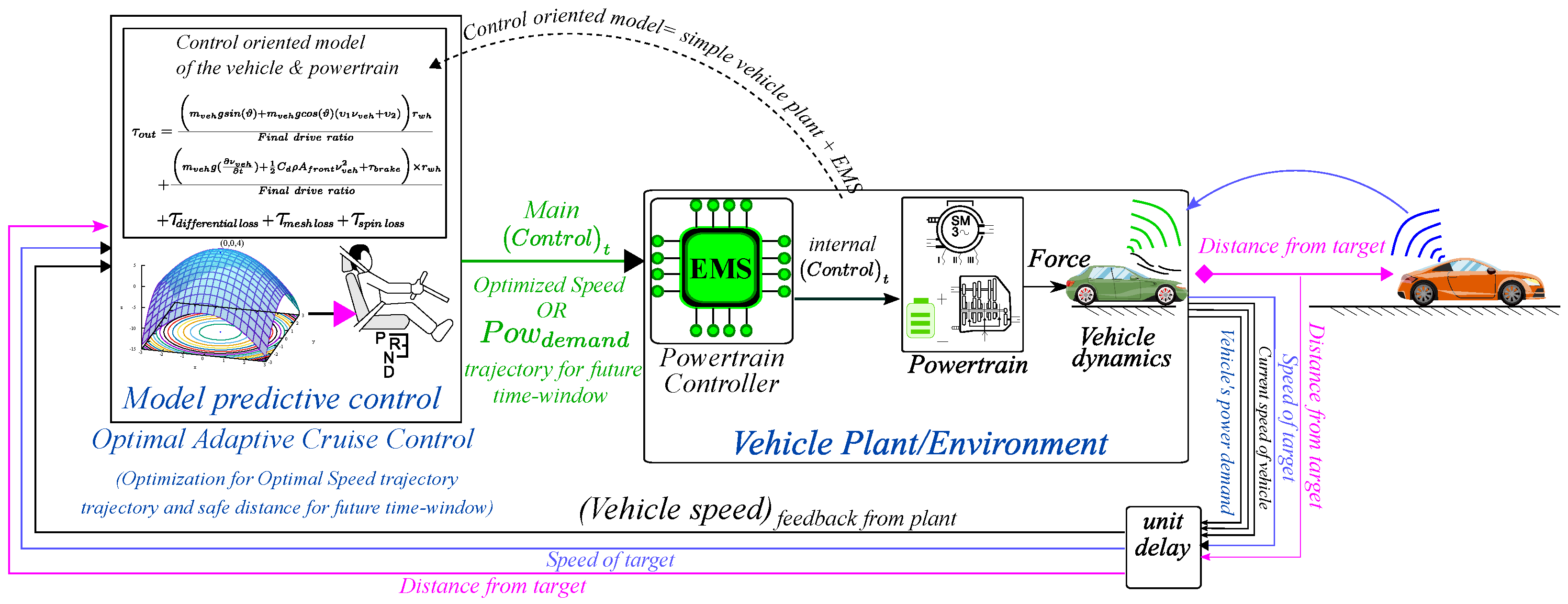
Looking at the strengths of V2V communication in designing an eco-driving feature for the adaptive cruise control module of the EV’s VCU and identifying the drawbacks of the existing literature, the authors are inspired to enhance the capabilities of OACC. The proposed OACC will improve energy efficiency, reduce battery SOH degradation, and maintain safe inter-vehicular distance by optimally controlling the acceleration trajectory for a short-term future time window in the presence of stochastic delay within V2V communication. As shown in
Figure 2, the fundamental idea of this intelligent feature is to consider the EV as an Ego vehicle and optimally control its acceleration trajectories for a short-term future time window by exploiting the Leading vehicle’s position and speed through a linear MPC.
Compared to the existing literature, this research article has the following contributions:
Formulating a less computationally expensive MPC framework for solving the OACC problem;
Fulfilling three objective simultaneously, i.e., energy efficiency, reducing battery SOH degradation, and maintaining safe inter-vehicular distance;
Making the MPC framework robust against external disturbances such as sensory noise and communication delays.
The paper is organized as follows. The paper introduces the vehicle model in
Section 2, providing a foundational understanding of the research context. Following this,
Section 3 formulates the problem of optimizing the speed profile, setting the groundwork for the subsequent sections.
Section 4 takes a closer look at the implementation of the MPC model, providing insights into how speed optimization is carried out. In
Section 5, the paper presents simulation results and engages in detailed discussions related to these findings Finally, the paper culminates in its concluding section, summarizing the work and drawing insights based on the research and its outcomes.
2. Forward Approach Electric Vehicle (EV) Modeling
This section will present the vehicle plant model, which serves as the foundational basis for implementing the proposed OACC. The model is designed to describe the longitudinal dynamics of a battery electric vehicle city car (2015 Chevy Spark) equipped with a single electric motor (EM), one inverter, and a single-gear transmission at the wheel level, as shown in
Figure 3. Throughout this section, the BEV city car under consideration will be referred to as the
Ego vehicle. The vehicle following a predefined driving cycle will be referred to as the
Leading vehicle.
2.1. Longitudinal Dynamics
In this subsection, we provide the equations that describe the forward model for the longitudinal dynamics of the Ego vehicle. These equations are essential for understanding the interactions between the vehicle’s speed, torque, and the various forces acting upon it. Equation (
1) describes the electric motor torque demand from the driver,
, determined through a proportional–integral (PI) controller which commands it according to the error between the desired speed
and the actual chassis speed
. Additionally, the contribution due to resistance forces, such as aerodynamics, rolling, slope, and inertia, are taken into account into
as follows:
Once the torque demand at the motor level is determined, the torque acting at wheel level
can be evaluated. This calculation considers the final drive transmission efficiency
and the final drive transmission ratio
and accounts for braking and accelerating. Calculation of
is given in Equation (
2), as follows:
Once the torque at wheel level is computed, it is possible to evaluate the chassis’s acceleration, speed, and position through Equation (
3), integrating the
term once and integrating it twice, respectively.
where the vehicle equivalent mass (
) considers the motor, final drive, and wheel inertias;
R is the wheel radius;
is the braking force; and
is the resistance force due to rolling, aerodynamics, and slope, as described in Equation (
4).
where
. The first component is the aerodynamic resistance force, the second indicates the road-slope-induced resistance force, and the third represents the rolling force. All the parameters used for mathematically modeling vehicle dynamics are listed in
Table 1.
2.2. Battery Model
A battery model based on data from [
31] has been implemented in the previously presented BEV architecture to ensure reliable and consistent results. This model simplifies the battery as a series and parallel connections of elementary cells. This representation includes a voltage generator representing the cell’s open circuit voltage (OCV) in series with a resistance representing the cell’s internal resistance. To match the energy storage performance of the actual Chevy Spark BEV, the cells from the paper were configured in 121 series and 22 in parallel. These cells are A123 26650 LiFePO
4 lithium-ion cylindrical cells with a nominal voltage of 3.3 V and a rated capacity of 2.5 Ampere-hours (Ah). To implement this model, some preliminary assumptions were made. First the elementary cell has been included as a voltage generator in series with an internal resistance considered adequate for assessing battery dynamics in this study. Then, it has been assumed that the BMS can maintain the temperature of the pack constant at 25 °C regardless of external temperature and load conditions. The internal resistance is also considered equally in both charging and discharging conditions. Lastly, uniform cell discharge/charge levels across the battery pack have been considered thanks to BMS working correctly.
2.3. State of Health Estimation Model
As outlined in [
31], the attainable maximum capacity of a battery progressively diminishes as the it undergoes degradation. This, in turn, translates into a diminished range for the battery’s operation. Furthermore, the OCV declines and internal resistance increases due to the natural wear and aging of internal components (SOH decreases), as shown in
Figure 4a,b where experimental data from battery fading test illustrated in [
31] are considered.
Since directly measuring the SOH of a battery is not feasible, an analytical method with empirical fitting has been developed using a mathematical model exploiting the Arrhenius relation and a Coulomb counting method to estimate the current SOH of the battery. Equation (
5) allows us to evaluate the cell capacity loss as a percentage:
where
represents the cell capacity loss as a percentage and
B is a pre-exponential factor determined through the experimental fitting of real data in [
31]. Its values vary with the current C-rate, considering both calendar aging and wear due to battery usage. The pre-exponential factor values are tabulated in
Table 2 below.
To ascertain the battery’s cycle life, we assume the EOL occurs when 20% of battery capacity is lost. By setting
% to 20% and inverting equation (V), number of cycles the battery can withstand up to EoL for a given C-rate and cell temperature can be calculated through Equation (
6):
where
is the rated battery capacity evaluated in Ampere-hours, which for an A123 cell is 2.5 Ah. Once this variable has been evaluated, it is possible to evaluate the
at a specific instant ‘
t’ integrating into the equation over time, as shown in Equations (
7) and (
8), providing the output of the estimator block:
In this case, the state of health for the initial condition is set to 1, indicating a new battery cell. After this block outputs the current SOH, it influences the cell’s OCV and internal resistance. Subsequently, it enters the SOC estimator, which evaluates the SOC simply as the ratio between the cell’s actual and maximum capacity, adjusting the second term to account for reduced energy storage capabilities due to degradation.
2.4. Simulation Setup
To establish a car-following simulation, which mathematically describes how vehicles follow one another on the road, the behavior of the leading vehicle to be followed must be selected. Two distinct driving cycles are employed to represent realistic scenarios: the Worldwide Harmonized Light Vehicles Test Cycle (WLTC), used in Europe, and the EPA cycle, utilized in the United States. This last cycle combines two sub-cycles: the Urban Dynamometer Driving Schedule (UDDS), simulating city driving conditions for testing Light-Duty Vehicles (LDVs), and the Highway Fuel Economy Test (HWFET). These two cycles aim to encompass diverse driving scenarios, ensuring comprehensive testing and evaluation of the BEV model. Several realistic assumptions were made regarding the environmental setup for the model:
Only two vehicles are present in the environment;
No vehicles enter or exit the lane;
Only longitudinal dynamics are examined and controlled;
All types of road conditions, from urban roads to highways, are considered without accounting for traffic, focusing solely on the actions of the Leading vehicle;
Information from the leading vehicle, including actual speed and position, is available through V2V or V2I communication or sensors, giving the possibility for the Leading and Ego vehicles to be either connected or not connected;
Disturbances in the Leading vehicle’s information are considered white noise with a specified maximum amplitude, accounting for sensor accuracy and communication delays.
In this scenario, the Ego vehicle’s initial conditions are SOC = 95%, SOH = 1, (initial vehicle speed), and (initial position).
3. Formulating the Speed Profile Optimization Problem
In the following paragraph, we elaborate on the OACC problem, giving the basis for the implemented MPC strategy.
4. Solving the Speed Optimization Problem with Linear MPC
This section delves into each facet of the linear MPC architecture, elucidating the steps in solving the acceleration optimization problem.
Figure 5 visually depicts the implementation of the concept in the Simulink
® platform, encapsulating the
Ego vehicle, the
Leading vehicle, and the MPC controller.
4.1. Definition of Controller Inputs
The initial and pivotal step entails defining the inputs for the controller. Employing the Simulink® 2022a for iteration block to account for iterations, careful consideration is given to the inputs necessary for accurate future predictions. The variables incorporated into the input blocks encompass all the essential states of both the Leading and Ego vehicles. These states are critical for evaluating the cost function outlined in the subsequent section and are indispensable for simulating the linearized vehicle model within the controller block.
4.2. Acceleration for Loop
Upon entering the MPC block, a nested structure of two
“For” loop blocks is employed. The external loop systematically tests various accelerations, while the internal loop assesses the optimal acceleration based on cost considerations over multiple time steps. To balance computational cost and result accuracy, the
“For” loop employs a more complex architecture. Recognizing the vehicle’s feasibility limits related to jerk and aiming to reduce the number of iterations, a linear relation is utilized:
Equation (
11) ensures that only feasible accelerations within the current
Ego vehicle’s acceleration range are tested, thereby reducing the number of iterations, enforcing feasibility limits, and enhancing comfort by limiting jerk values. However, avoiding an excessively narrow acceleration range is crucial to prevent impairment of the vehicle’s following capability and divergence of the simulation.
4.3. Cost Function
In MPC, the cost function, denoted as
J, is a mathematical function that assesses the cumulative performance of control inputs and system states over a finite prediction horizon
N. It is formulated as the sum of individual cost terms, as shown below:
The state cost function
quantifies how desirable or undesirable a particular state
and control input
are at each time step
k. For this application, key states include
Leading vehicle speed
,
Leading vehicle position (
,
Ego vehicle speed
and vehicle position
, and
Ego SOC
. The primary control action,
, is the commanded acceleration
. The central objective of the MPC is to determine the optimal control input
(in this case, acceleration) that minimizes the total cost
J, while satisfying system dynamics and input/output constraint
. In tailoring the cost function for our specific application, addressing requirements related to following capability and energy management is paramount. The designed total cost function
J is formulated as follows:
Within this comprehensive cost function, three primary contributions are discerned, each focusing on specific control aspects: The component
is pivotal in maintaining the vehicle within the desired distance range, considering distance errors at future time steps. The parameter
provides a mechanism for adjusting the weight allocated to these desired distance constraints. Additionally,
signifies the maximum allowable distance, serving to normalize the distance term. The inclusion of the square term enables the consideration of both positive and negative deviations as detrimental, contributing to a comprehensive evaluation. The key variable in this factor is defined as
Breaking this down, the first difference represents the vehicle distance at the next step, aligning it with the desired distance based on the vehicle’s speed shown by the second term. Here,
signifies the desired distance when both vehicles are stationary, set at 5 m.
enables the
Ego vehicle to conform, to a varying degree, to a predefined vehicle speed profile. Similar to the
term, a normalization process is implemented to adapt to the maximum speed variation prescribed between the two vehicles. The introduction of the square term serves the same purpose as in the preceding case, allowing consideration of both positive and negative variations as impactful. The parameter
assumes the role of the weighting factor, influencing the overall impact of this contribution in the cost function.
where the
term encapsulates the difference between the
Ego vehicle’s state of charge (SOC) in the subsequent time step and its current state.
The weighting factor for this term is designated as to establish a hierarchy in cost assignment compared to the other two components. This formulation ensures that an increase in the weight of a factor results in a proportionate rise in cost, emphasizing its impact on the overall cost function. Like the distance and speed terms, the term acts as a normalization factor. In contrast to the squared terms applied to distance and speed, the SOC factor remains unsquared. This decision stems from acknowledging that its negative effect should be considered exclusively when the SOC decreases, not in both directions. Thus, a minus sign is introduced into the function to underscore higher costs for actions causing substantial negative variations in SOC. The weight parameters were strategically selected to prioritize energy consumption while assigning relatively lower importance to speed and distance factors, while always ensuring safety constraints are met. This balance permits more extensive variations in speed and distance from the nominal values, promoting smoother velocity profiles while still providing adequate following capability. Specifically, was configured to a value of 0.15, and was set to 0.05 for these reasons.
4.4. Linearized Vehicle Model
The implemented strategy establishes a linear relationship between vehicle states and the control variable, significantly reducing simulation costs. Assuming precise replication of the imposed driving cycle by the Ego plant, the future Ego vehicle speed, position, and acceleration can be linearly evaluated based on the command input. A different approach has been required for the correlation between command input and Ego battery SOC.
In this case, a linear relation between command acceleration and the ratio has been found through multiple simulations. The choice of this specific ratio has been dictated by the dependence of the cell current on the acceleration and the current vehicle speed. This approach has enabled a significant simplification of the vehicle model, facilitating the estimation of all required vehicle states and allowing for the computation of the cost function multiple times within the predictive horizon.
4.5. Linear MPC with Predictive Horizon = 10 and Control Horizon = 2
Having undertaken these activities to drastically reduce computational costs, the final step involves finding the optimal balance between performance and computational efficiency. Through multiple simulations, the optimal configuration was identified with a predictive horizon (P.H.) of 10 and a control horizon (C.H.) of 2. In this scenario, the prediction horizon is sufficiently large to ensure a smooth profile without an excessively long horizon, which could lead to incorrect predictions. This is crucial, especially considering the assumption of a constant Leading vehicle speed, preventing overshoot in the Ego vehicle’s actions during transitions from braking to accelerating and vice versa.
Adjusting the predictive horizon (P.H.) is achieved by increasing the number of iterations for the internal loop, whereas controlling the control horizon (C.H.) is a different process. The control horizon represents the time or states in the future for which the controller actively computes and applies control inputs to the system. The solution implemented here involves a control horizon (C.H.) greater than 1, specifically set to 2, operating with constant acceleration during this period.
To predict values every two time steps and act on the plant accordingly in the subsequent two time steps, a Simulink® 2022a ‘Rate Transmission’ block was incorporated. This block adjusts the sampling frequency of its output, modifying the operational response of the subsequent blocks. Placing this block before the MPC controller and setting the output sampling frequency to half of the simulation frequency ensures results every two simulation time steps.
Upon exiting the MPC controller block, the rest of the Simulink® model must revert to working with the normal sampling frequency. Therefore, another ‘Rate Transmission’ block with an output frequency equal to the simulation frequency was introduced. Given that the input to this block is generated every two simulation time-steps, the remaining time step is kept constant, equal to the last output value. This architecture enables the prediction of a single commanded acceleration while acting on two time-steps, significantly reducing computational costs and spreading MPC predictions over two time-steps.
5. Simulation Results and Discussion
This section presents the simulation results of the
Ego vehicle in comparison to the
Leading vehicle following the WLTC and EPA driving cycles in
Section 5.1 and
Section 5.2, respectively. The effectiveness of the proposed OACC was evaluated in terms of energy efficiency, battery durability, and driver’s comfort.
5.1. WLTC-Based Results
In this case, the
Leading vehicle is following the WLTC cycle, and the
Ego vehicle is receiving continuous information about the
Leading vehicle’s speed and position. The VCU of the
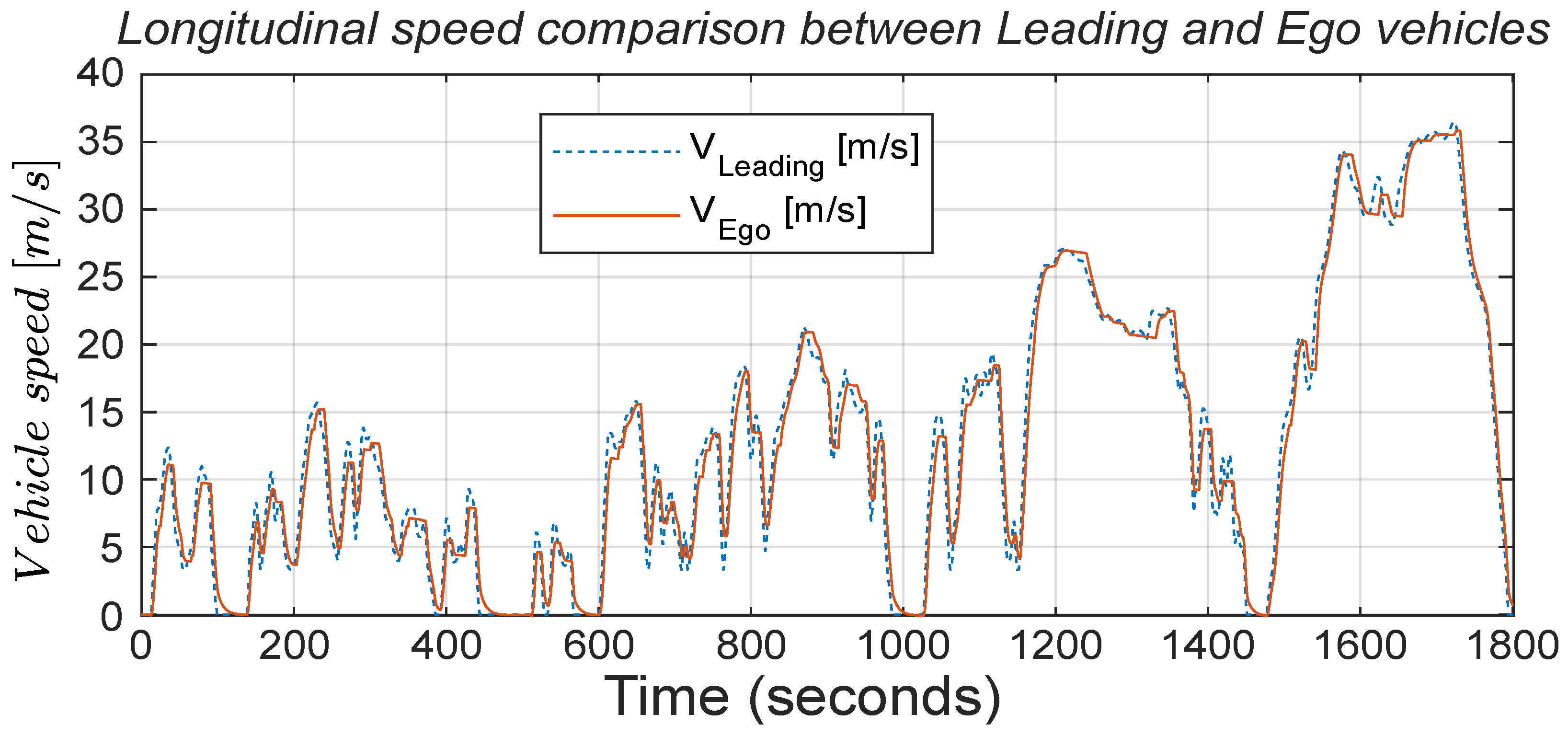
Ego vehicle, featuring the MPC, optimally plans its vehicle speed trajectory. The speed trajectories of the two vehicles are compared in
Figure 6.
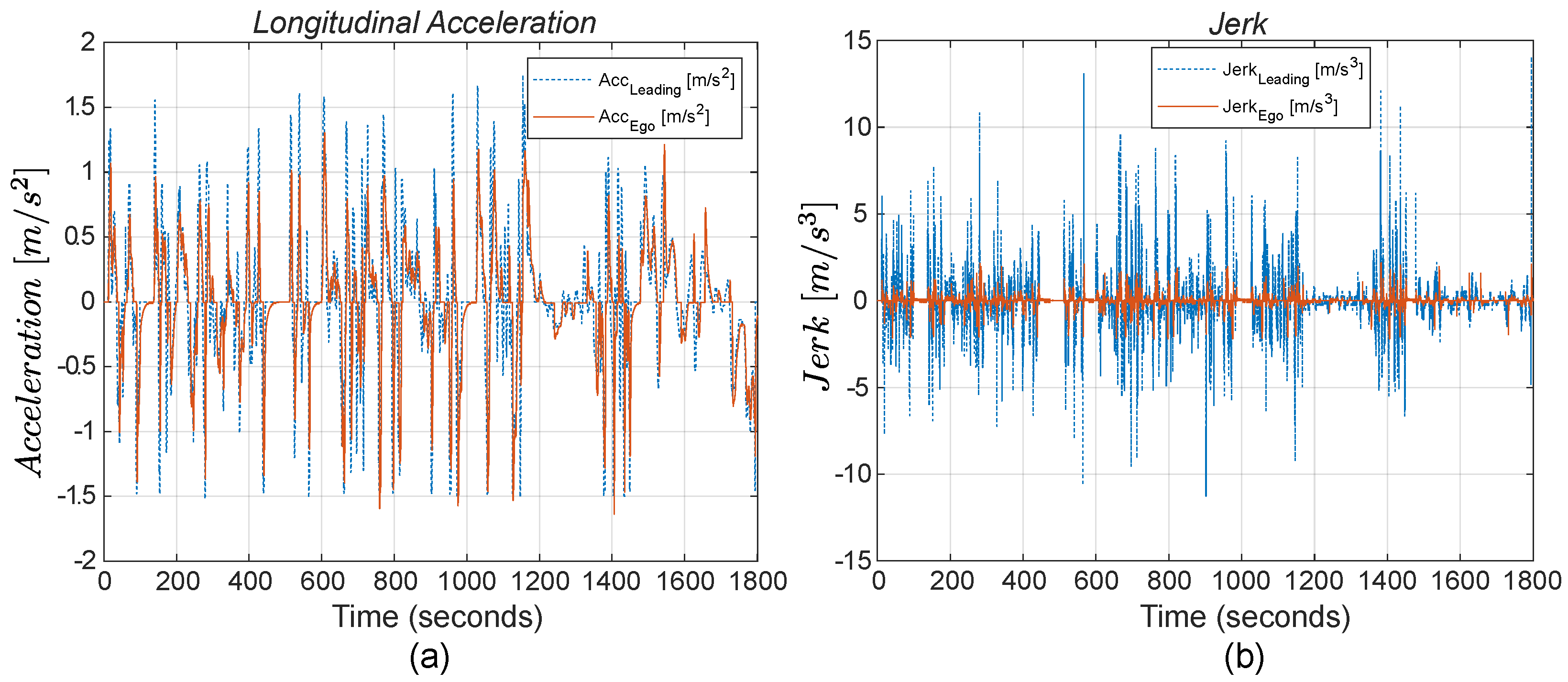
The acceleration command exhibits significantly less oscillation, with considerable reductions in all peaks due to the application of OACC, as shown in
Figure 7a. The “continuous” and “dashed” lines represent the
Ego and the
Leading vehicles’ acceleration profiles, respectively. During deceleration, a smoothing effect is possible due to the soft constraint on distance, which allows for larger variations. This is possible thanks to the distance constraint, which prevents the speed from rapidly reaching zero to approach the desired distance when the vehicle is stationary. This allows for a gradual reduction in speed until reaching a distance of 5 m.
This approach provides a substantial reduction in power requests. Furthermore, in terms of comfort, jerk values are greatly reduced in all conditions, more than halved, as shown in
Figure 7b, indicating that the controller operates more effectively and smoothly.
Examining the speed profiles in
Figure 6, it is evident that the initial objective set at the beginning has been successfully achieved. The
Ego vehicle, predicting future vehicle behavior of the
Leading vehicle, optimizes its trajectory, smooths its speed profile, and avoids the oscillations present in the behavior of the
Leading vehicle. All speed peaks are diminished, and the vehicle approaches zero speed more smoothly, sometimes even avoiding stops when the
Leading vehicle comes to a halt for the previously mentioned reason. In many instances, the
Leading vehicle experiences rapid positive and negative speed changes, but our
Ego vehicle effectively smooths them out, exhibiting nearly linear behavior. Moreover, the inter-vehicle distance is smartly managed by the
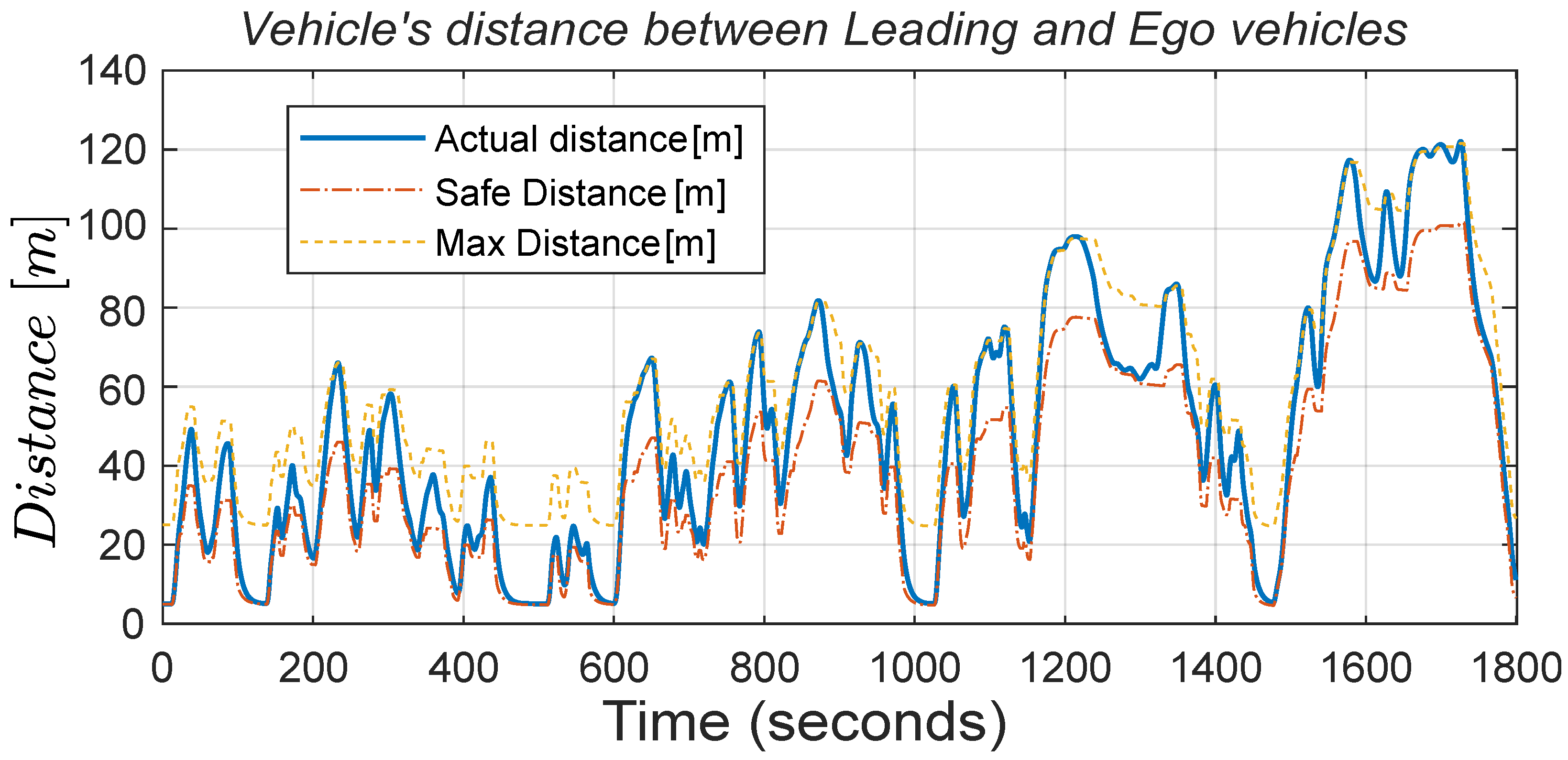
Ego vehicle’s OACC, varying as much as needed within the desired interval without ever falling below the safety distance or exceeding the maximum limit, as shown in
Figure 8. This figure shows how effectively the OACC varies the inter-vehicular distance within the boundaries set between a safe distance to the maximum distance to optimally regulate the vehicle’s acceleration.
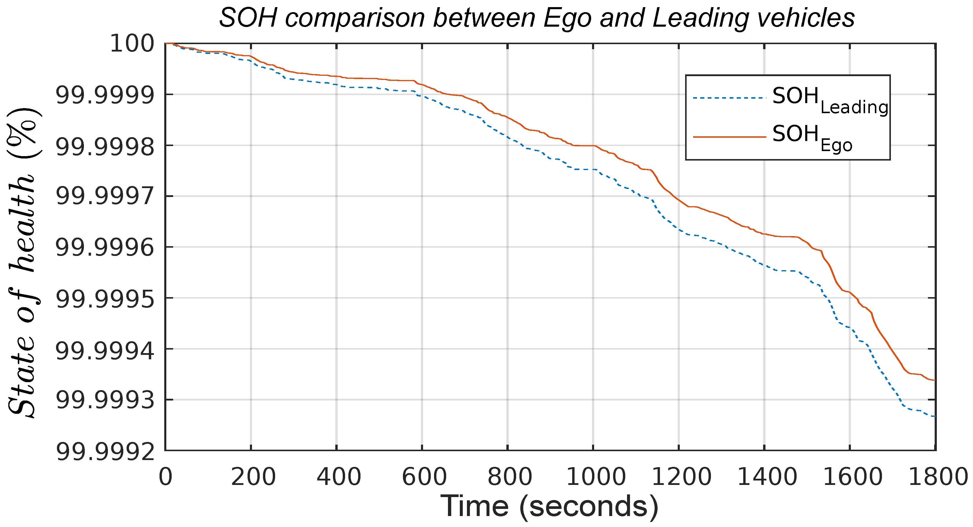
The improvements achieved with this approach are more significant, with a 3.7% reduction in energy consumption and a 9.7% reduction in battery SOH degradation, as shown in
Figure 9 and
Figure 10, respectively. The respective battery SOC trajectories indirectly measure the comparison between energy consumption for the
Ego and
Leading vehicles, whereas the reduction in SOH degradation in the
Ego vehicle is directly measured by comparing the SOH trajectories for two vehicles in
Figure 10.
These values are primarily due to the improvements obtained in
Figure 7a with a 6.5% reduction in maximum acceleration, indicating a decrease in power demand. Regarding comfort,
Figure 7b shows an 81% reduction in jerk peaks, ensuring a substantial improvement for passengers. These improvements are achieved while keeping travel time almost constant, with a difference of only 5 s for the same distance traveled.
5.2. EPA-Based Results
All these experiments were replicated for the EPA cycle, showcasing the ability to improve energy efficiency and battery durability performances in a different driving scenario.
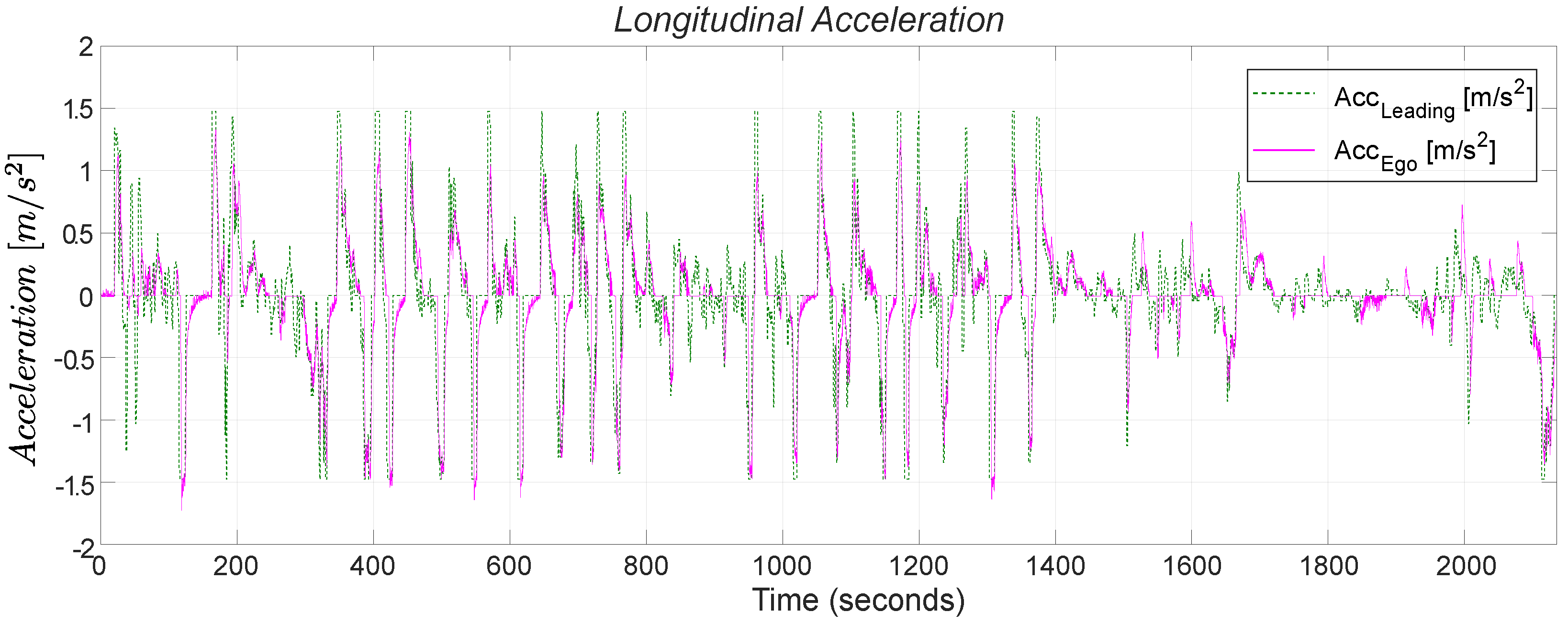
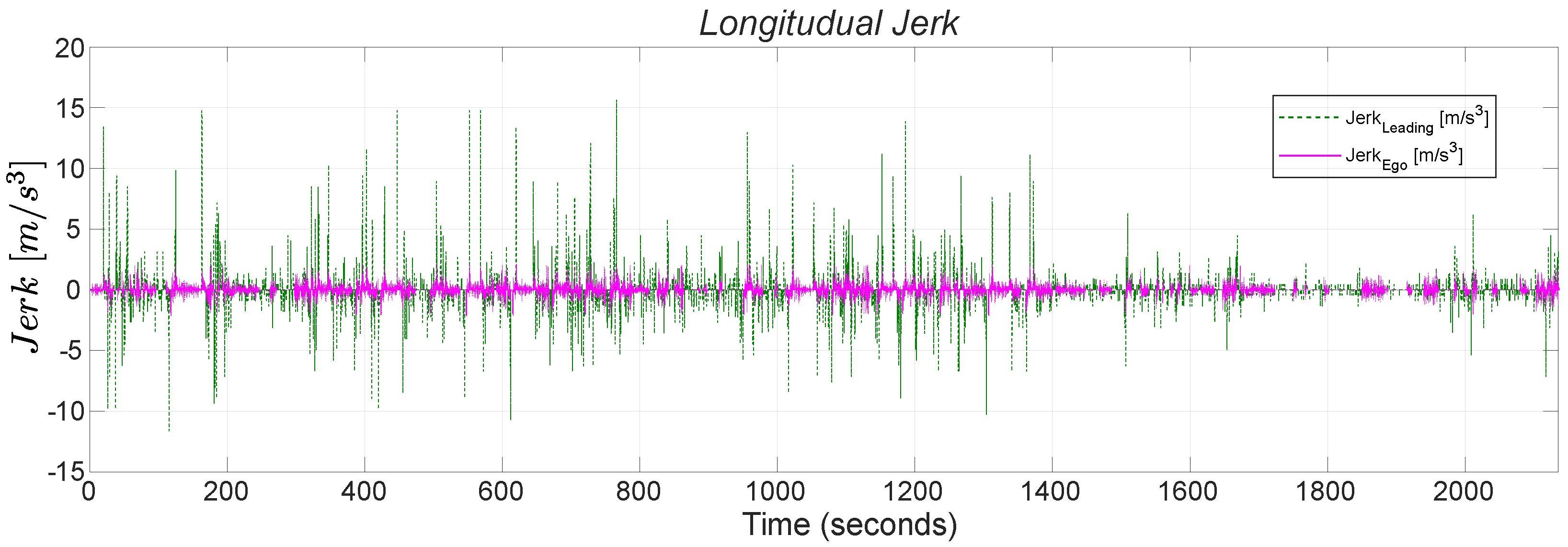
Figure 11 and
Figure 12 show the comparison between the vehicles regarding vehicular acceleration and jerk, respectively. In this case, given the less aggressive nature of the cycle, the improvements are naturally more minor but still substantial. Since these experimental charts do not provide additional information beyond what has been explained, only two figures illustrating speed smoothing are compared to the results following a
Leading vehicle, ensuring completeness. Even for this cycle, all the previously stated findings are reaffirmed, with a significant 7.6% reduction in battery SOH degradation and a 2.8% reduction in energy consumption.
Table 4 comprehensively furnishes all metrics of improvements resulting from the OACC for the
Ego vehicle under WLTC and EPA cycles.
5.3. Robustness Analysis: Noise and Delay Influence
To enhance the realism of the simulation, we considered incorporating noise and data delays in the Leading vehicle’s information. We incorporated two simple blocks into the input for Leading vehicle speed and Leading vehicle position to introduce these external disturbances: a delay block and band-limited white noise. Since our application is non-safety-related, we used 5G cellular network technology for communication and a specific radar, LLR4 [
3], commonly used in vehicle applications.
Given a simulation time-step of 100 ms in Simulink
®, the minimum delay we could have implemented is at least that value. As outlined in [
3], the delays associated with these technologies are notably lower:
The long-range radar has a cycle time of 60 ms, indicating how frequently the sensor collects and processes data or updates its measurements.
Average latency values, representing the delay or lag in data transmission between a sender and receiver, for specific countries are 32 ms for the United States (US) and 37 ms for Italy. While these values are averages and can vary by country, they provide a helpful reference, especially since they are lower than the sensor-induced delay.
This presents a situation where the implemented delay exceeds the actual delay, resulting in an overestimation of the disturbance.
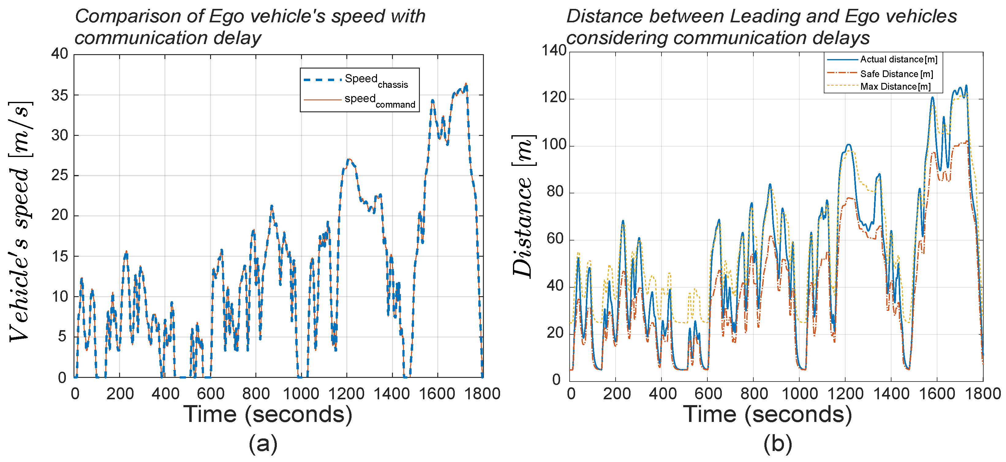
Within one time step, assuming worst-case scenarios with maximum speeds in the WLTC, the speed variation is approximately 0.175 m/s, and the distance travelled is around 3.6 m. Given these values, we expect practically negligible variations in the speed profile and more significant changes in relative distance, as shown in
Figure 13a. Particularly with respect to distance values, the
Ego vehicle’s controller consistently receives delayed information, effectively acting as if it were one time step behind. This discrepancy causes the actual accurate distance to be poorly managed, leading to unnecessary increases in the gap from the
Leading vehicle at each moment, resulting in the vehicle being out of the upper bound limit. While this is almost imperceptible in speed, it is more noticeable in the relative distance. The phenomenon is illustrated in
Figure 13b for the WLTC cycle.
This behavior has minimal influence on the results. The SOC and SOH remain practically the same because the MPC operates as precisely as before, and the effect on distance goes unnoticed since the controller continuously considers the delayed information it receives. The simulation results on the EPA cycle with such disturbances and communication delays demonstrate a similar pattern. The second aspect that requires consideration is the presence of noise in the acquired information. Due to their nature, sensors inherently possess some degree of error in their measurements, leading to variations from the nominal values. This variation is precisely what sensor accuracy describes. For instance, ref. [
3] indicates that the speed and distance measuring error achievable with the described long-range radar are approximately ±0.11 m/s and ±0.12 m, respectively.
Given this information, we introduced white noise with an amplitude within this specific range and a frequency equal to the simulation frequency (10 Hz) into our input signals. The addition of this noise has a more significant impact compared to the introduction of communication delays. This is because noise introduces oscillations in the commanded acceleration, which, even if to a small extent, deteriorates performance. Consequently, this effect results in a decrease in performance compared to improvements without noise, amounting to −2.17% of 3.7% for SOC and −2.3% of 9.7% for SOH improvements. These values are obtained when simulating a WLTC. However, the decrease is nearly the same for the EPA, with −2.78% for SOC and −2.4% for SOH. This is because its detrimental impact is independent of speed, unlike the delay.
6. Conclusions
The presented OACC is a valid solution for reducing battery health degradation and energy consumption in EVs by optimally and dynamically controlling vehicle acceleration and reducing peak power requests. The OACC decreases the energy consumption of a simulated passenger EV by as much as 3.7% and reduces battery health degradation by as much as 9.7% while always maintaining a safe inter-vehicle distance. Simply acting at the software level, the MPC can be easily integrated into any powertrain architecture with an autonomous driving level equal to 1, enforcing its broad applicability in the current automotive industry. Moreover, the proposed OACC’s performance is promising, considering it is designed to be as light as possible, especially in more aggressive driving scenarios where its effect is more evident. As further analysis, the controller has been tested under realistic disturbance and scenarios with delayed V2V communication, showing excellent robustness and confirming its effectiveness and practicability. The real-time hardware-in-the-loop validation of the proposed OACC is planned as a future work. In summary, the OACC controller proposes an innovative architecture to address current critical automotive challenges, with promising results, highlighting its potential for widespread adoption and positive impact on the electric vehicle landscape. As the possibility of leveraging V2V communication in reshaping the EMS and adaptive cruise control frameworks is increasing, this research will motivate future scholars to investigate the effectiveness of OACC in traffic situations with signalized intersections and different highway driving conditions.
