Abstract
Aiming at the demand for subjective evaluation of driveability for fuel cell vehicles, the modeling and evaluation method of driveability for fuel cell vehicles were studied in this paper. Firstly, a real-time model of the fuel cell vehicle powertrain system was established, which included the fuel cell model, power battery model, DC/DC converter model and drive motor model. Secondly, it was integrated with the vehicle dynamics model to form a virtual prototype of a fuel cell vehicle. And a virtual subjective evaluation platform for fuel cell vehicles was built by combining the virtual prototype and high-fidelity driving simulator. Thirdly, a subjective evaluation method of driveability for fuel cell vehicles was proposed, which included the starting performance, acceleration performance, uniform speed performance and tip-in/tip-out performance. Finally, the paper used the platform and method mentioned above to conduct subjective evaluations of the fuel cell vehicles.
1. Introduction
As one kind of new energy vehicle, fuel cell vehicles provide power through fuel cells and use motors as driving devices. The reaction product is only water and the energy conversion rate is high, so fuel economy can be effectively improved and zero emissions can be achieved, which is one of the most important directions for the development of vehicles [1]. Compared with traditional vehicles, the powertrain system of fuel cell vehicles consists of fuel cells, power batteries and drive motors. In addition to the power battery, the supercapacitor is also sometimes used as the auxiliary power source to prevent overcharging and discharging of the power battery [2,3]. It results in significant changes in vehicle mass and load distribution. And due to the impact of characteristics of fuel cells and motors, the driveability of fuel cell vehicles is different from that of traditional cars. Therefore, studying the modeling and evaluation methods of driveability for fuel cell vehicles is of great significance.
The driveability of vehicles refers to the longitudinal dynamic performance reflected in the driving process, which shows the vehicle response characteristics to the driver’s inputs and the driver’s feeling of the vehicle response. It is usually evaluated by the subjective scoring of professional drivers. Therefore, the modeling and evaluation of drivability for fuel cell vehicles need not only the high-precision model of the powertrain and vehicle dynamics but also the driving simulator and other simulation platforms that can be used for subjective evaluation.
In terms of the research on the driveability of traditional vehicles, List et al. proposed a vehicle driveability evaluation system [4]. Schoeggl et al. proposed a subjective and objective evaluation method for vehicle driveability [5]. Hayat et al. established various subsystem models that affect driveability [6]. Zehetner et al. proposed a new method for the economy, emission and driveability [7]. A method that can quantitatively evaluate the driveability of heavy vehicles was proposed [8]. Walters et al. evaluated the driveability of vehicles through the co-simulation method of the complex engine model and the vehicle dynamics model [9]. Lakshmanan et al. proposed a subjective and objective evaluation method for the driveability of commercial vehicles [10]. Castellazzi et al. studied the influence of powertrain dynamics on vehicle driveability [11]. A fuzzy hierarchy quantization method on the basis of an analytic hierarchy process and fuzzy method to quantify the relevant indicators of driveability was designed [12]. Chandrasekaran et al. conducted a correlation study between the subjective and objective evaluation of the drivability of compact SUVs [13]. A driveability evaluation model based on the optimization of an extreme learning machine and principal component analysis was proposed [14]. An approach for objectified drivability evaluation and classification of passenger cars based on physical criteria was presented [15]. Zhou et al. proposed an intelligent driveability objective evaluation model based on analytic hierarchy process and rough set method for passenger cars with a dual-clutch transmission and took the static gearshift condition as an example for research [16]. Huang et al. proposed a driveability evaluation model based on fuzzy dynamic weights and determined the evaluation indicators that affect driveability in tip-in conditions [17]. A driveability objective evaluation model for the passenger car powertrain was developed, which was, on the basis of prior knowledge, SMART principle and principal component analysis [18]. In addition, an improved fuzzy comprehensive evaluation method was proposed, which considered the subjective and objective consistency [19].
In terms of the research on the driveability of new energy vehicles, Wei et al. proposed an evaluation method for the economy, power and driveability of hybrid electric vehicles [20]. Yang et al. conducted subjective and objective evaluations of PHEV passenger cars regarding the impact of complex control strategies and operating modes on driving performance [21]. A driveability evaluation of the battery electric vehicles equipped with multi-speed gearboxes in a static driving simulator was conducted [22]. A simulation model for driveability assessment and optimization of hybrid drive trains was also proposed [23]. Al Aawar et al. investigated the optimization method for the powertrain of hybrid electric vehicles to achieve good driveability [24]. Jauch et al. developed a generic model of the driveline of a plug-in hybrid vehicle [25]. A fuzzy evaluation method for the driveability of new energy vehicles was proposed [26]. Barroso et al. evaluated the driveability of electric vehicles applying different regenerative braking strategies based on a driving simulator integrated with a vehicle model [27].
It can be seen from the above analysis that scholars have proposed some driveability evaluation methods for traditional vehicles and new energy vehicles, but there is no modeling and evaluation method of driveability for fuel cell vehicles. Aiming at the demand for driveability evaluation for fuel cell vehicles, this paper establishes a real-time model of the fuel cell vehicle powertrain system and builds a virtual subjective evaluation platform for fuel cell vehicles. At the same time, it proposes a subjective evaluation method of driveability for fuel cell vehicles and analyzes the drivability evaluation results of the virtual prototype of a fuel cell vehicle.
2. Methods
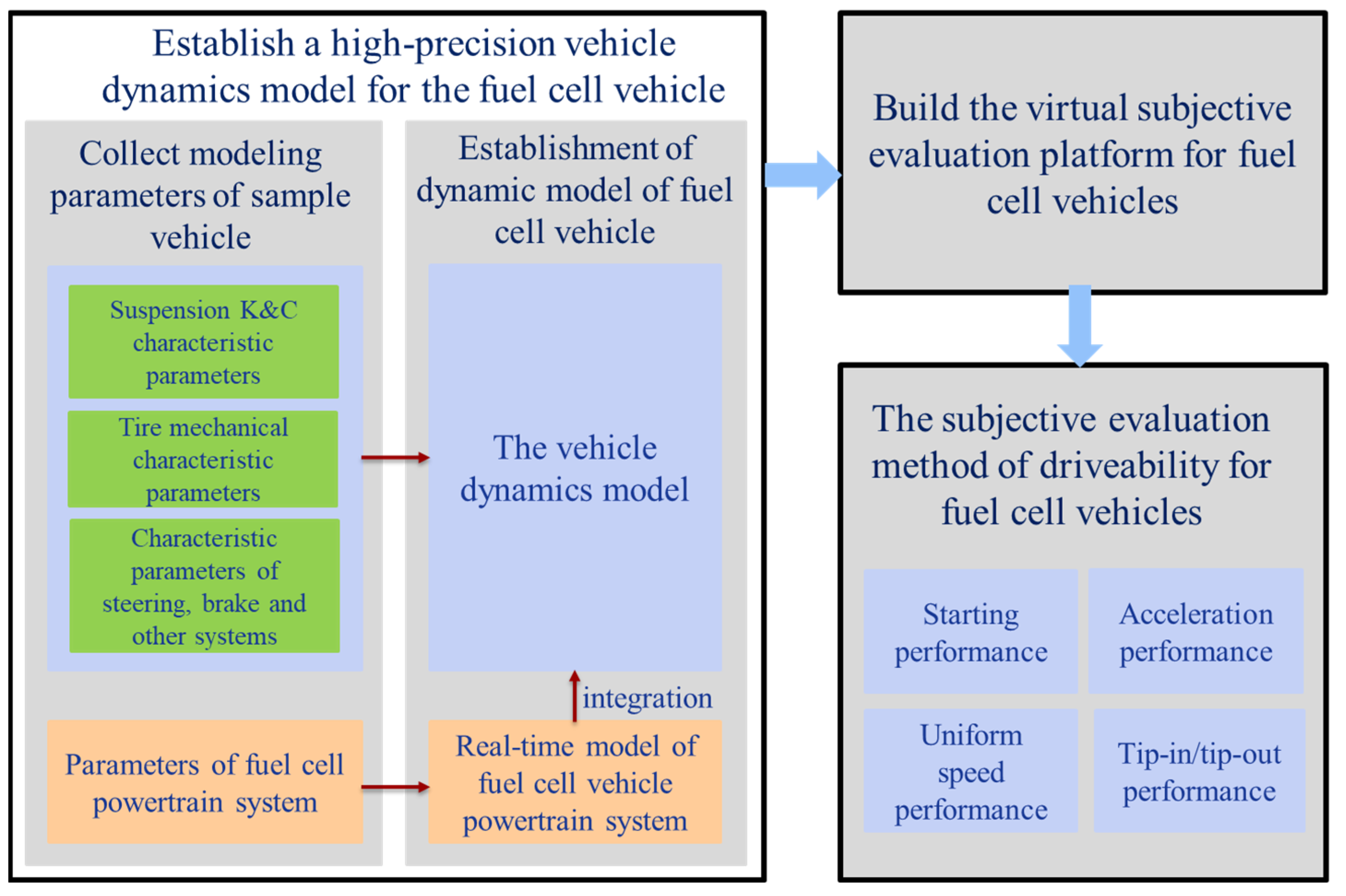
In response to the demand for the evaluation of fuel cell vehicle driveability, this paper proposes a method for modeling and subjective evaluation of fuel cell vehicle driveability. As shown in Figure 1, the main research methods of this paper are as follows: the parameters of the fuel cell vehicle prototype, including suspension, tires, steering, brake, the fuel cell vehicle powertrain system and other characteristic parameters, are utilized to complete the modeling of the vehicle dynamics and fuel cell powertrain system and achieve the integration of the fuel cell powertrain system and the vehicle dynamics model. Next, the integration of the fuel cell vehicle model and the automobile driving simulator are realized and a subjective evaluation platform of driveability for fuel cell vehicles based on the automobile driving simulator is formed. Finally, the differences between fuel cell vehicles and traditional fuel vehicles in terms of powertrain systems is fully considered, and the evaluation method suitable for the driveability of fuel cell vehicles is proposed. Evaluators are proposed to score the starting performance, acceleration performance, uniform speed performance, and tip-in/tip-out performance of the fuel cell vehicle and obtain corresponding subjective evaluation results.
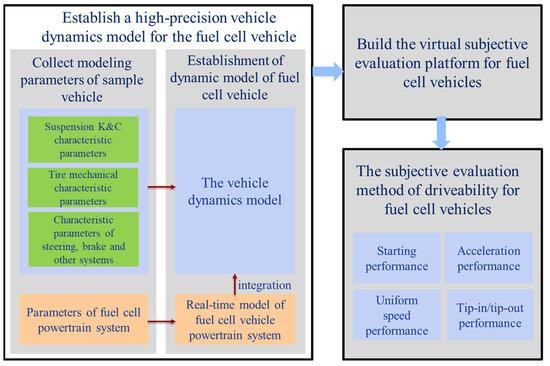
Figure 1.
The main research methods.
3. Real-Time Model of Fuel Cell Vehicle Powertrain System
3.1. Fuel Cell Model
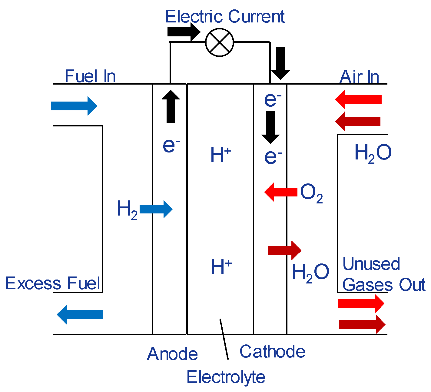
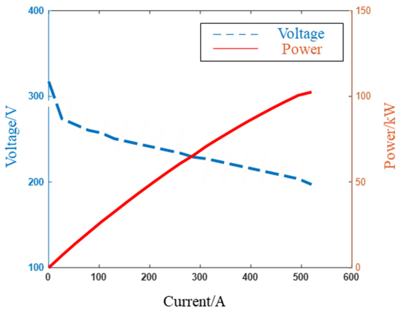
The schematic diagram of the structure of proton exchange membrane fuel cells is shown in Figure 2. The reaction of fuel cells can be seen as two semi-electrochemical reactions, namely the oxidation reaction of hydrogen at the anode and the reduction reaction of oxygen at the cathode. In this paper, the model of the proton exchange membrane fuel cell (PEMFC) is established. The polarization curve of PEMFC reflects the relationship between steady voltage and current density or current of the fuel cell. The polarization curve of the fuel cell is shown in Figure 3.

Figure 2.
The structure of the proton exchange membrane fuel cell.
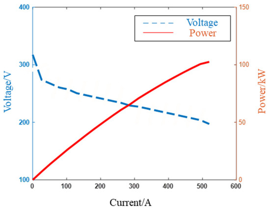
Figure 3.
Polarization curve of the fuel cell.
The voltage calculation formula of the electrochemical model of the proton exchange membrane fuel cell established is:
where is the ideal open circuit voltage of the fuel cell, is the cathode voltage loss, and is the ohmic loss. The ohmic loss can be expressed as:
where is the stack current density, is the stack current, is the effective activation area of the proton exchange membrane fuel cell, and is the resistance of the fuel cell.
3.2. Power Battery Model
Considering the power and dynamic response characteristics of the fuel cell, fuel cell vehicles are usually equipped with a power battery. In this paper, the equivalent circuit model of the lithium-ion power battery is established, and its principle is shown in Figure 4.
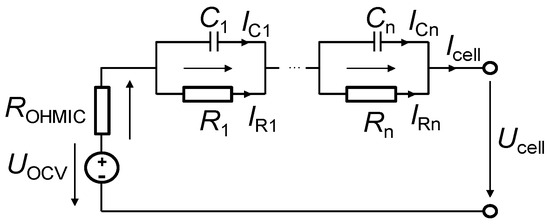
Figure 4.
Equivalent circuit model of lithium-ion power battery.
According to the equivalent circuit, the voltage of the lithium-ion power battery is related to the current, open circuit voltage and internal resistance. The relationship between them can be expressed as:
where is the open circuit voltage, is the current of the fuel cell, is the resistance, is the electric charge of the capacitor, is the current flowing through the capacitor, is the capacitance of the capacitor in the resistor-capacitance (RC) element, and n is the number of RC elements.
3.3. Drive Motor Model
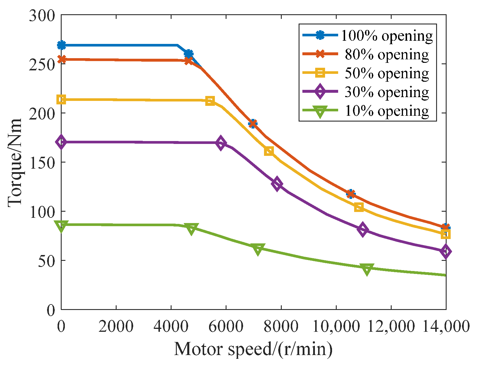
As an important component of the fuel cell vehicle powertrain system, the drive motor affects the driveability of fuel cell vehicles under different complex conditions. In this paper, the internal mechanism of the drive motor is not considered, and the external characteristic model of the drive motor at different accelerator pedal openings is established as shown in Figure 5.
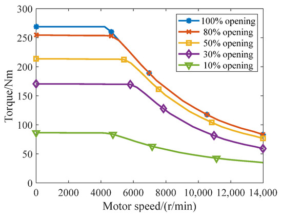
Figure 5.
External characteristic model of the drive motor at different accelerator pedal openings.
The target motor torque is calculated by looking up a two-dimensional characteristic table based on the current motor speed and accelerator pedal opening:
where is the target motor torque, is the current motor speed, and is the accelerator pedal opening.
To dynamically describe the change process of motor torque, a first-order hysteresis is adopted to describe the dynamic process between the target motor torque and the actual motor torque:
where is the actual motor torque; and is the time constant, which can be obtained through a motor test.
The drive motor converts electrical energy and mechanical energy when the fuel cell vehicle is in the starting, accelerating, braking and other conditions. In the process of energy conversion, there will be a certain loss of motor power. As shown in Figure 6, the drive motor model established in this paper uses the motor working efficiency map to determine the working efficiency of the drive motor, which reflects the motor energy conversion efficiency under different motor angular velocities and torques. The range of energy conversion efficiency that may occur during the operation of the drive motor is 85–98%.
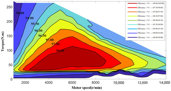
Figure 6.
The motor working efficiency map.
3.4. DC/DC Converter Model
The DC/DC converter is an important component of the fuel cell vehicle powertrain system, which can stabilize and transform the voltage. The DC/DC converter has a voltage type and current type. A current-type DC/DC converter model is established in this paper, and its working principle is shown in Figure 7.
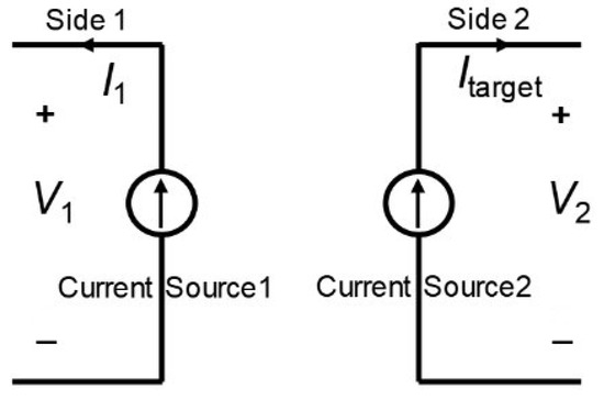
Figure 7.
Equivalent circuit of the current-type DC/DC converter model.
When switching from Side 1 to Side 2, the equivalent circuit of the DC/DC converter can be expressed as:
where and are the voltage and current of Side 1, respectively; and are the voltage and current of Side 2, respectively; and is the efficiency of the DC/DC converter.
4. Virtual Subjective Evaluation Platform for Fuel Cell Vehicles
In order to evaluate and analyze the driveability of fuel cell vehicles in the virtual environment, this paper integrates the real-time fuel cell powertrain system and the vehicle dynamics model. And they are embedded into the high-fidelity driving simulator to achieve the driveability evaluation of fuel cell vehicles.
4.1. Integration of Fuel Cell Vehicle Dynamics Model
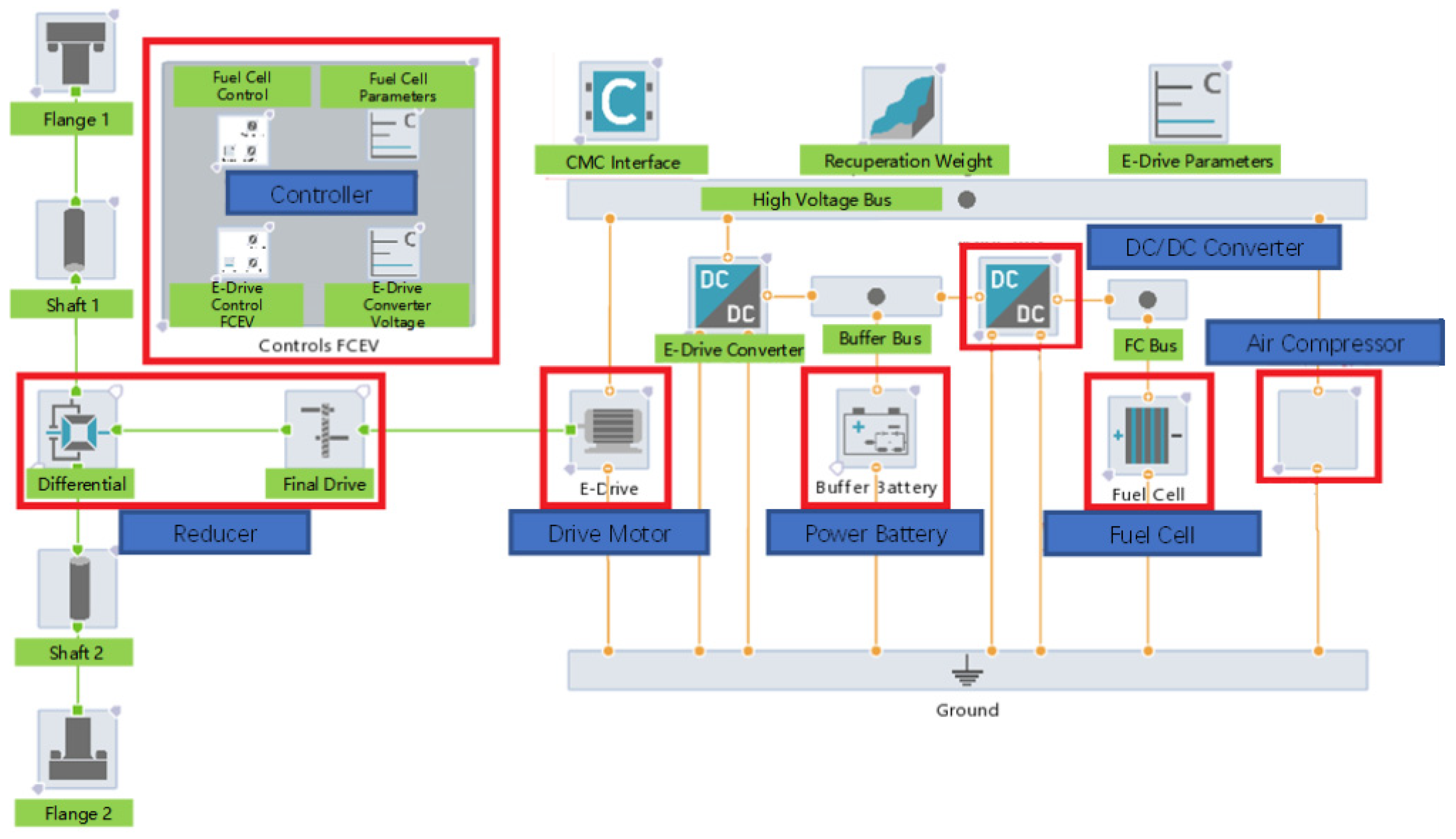
As shown in Figure 8, the model of the fuel cell vehicle powertrain system is realized in AVL/Cruise M [28]. The controller includes control algorithms for fuel cells and motors. And the reducer consists of the final reduction drive and the differential. It is integrated with the high-fidelity vehicle dynamics model [29] in Matlab/Simulink [30], in which the powertrain system in the vehicle dynamics model is replaced by the fuel cell vehicle powertrain system model. The vehicle dynamics model is written in C language, and the code is compiled into a dll file using a compiler. The s-function module is created in Matlab/Simulink to call the dll file, and the vehicle dynamics model is finally expressed in Matlab/Simulink. In order to coordinate the braking energy recovery and energy management, the vehicle controller model is also implemented in AVL/Cruise M.

Figure 8.
The model of the fuel cell vehicle powertrain system based on AVL/Cruise M.
The integration relationship between the fuel cell vehicle powertrain system and the vehicle dynamics model is shown in Figure 9. The fuel cell vehicle powertrain system obtains the accelerator pedal signal, braking pedal signal and master cylinder pressure from the driver, and the wheel speed and longitudinal speed signals are obtained from the vehicle dynamics model. It uses the above signals to calculate the torque and transfer it to the vehicle dynamics model to solve the vehicle motion.
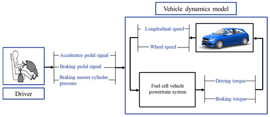
Figure 9.
Integrated diagram of fuel cell vehicle powertrain system and vehicle dynamics model.
4.2. Evaluation Platform of Driveability for Fuel Cell Vehicles
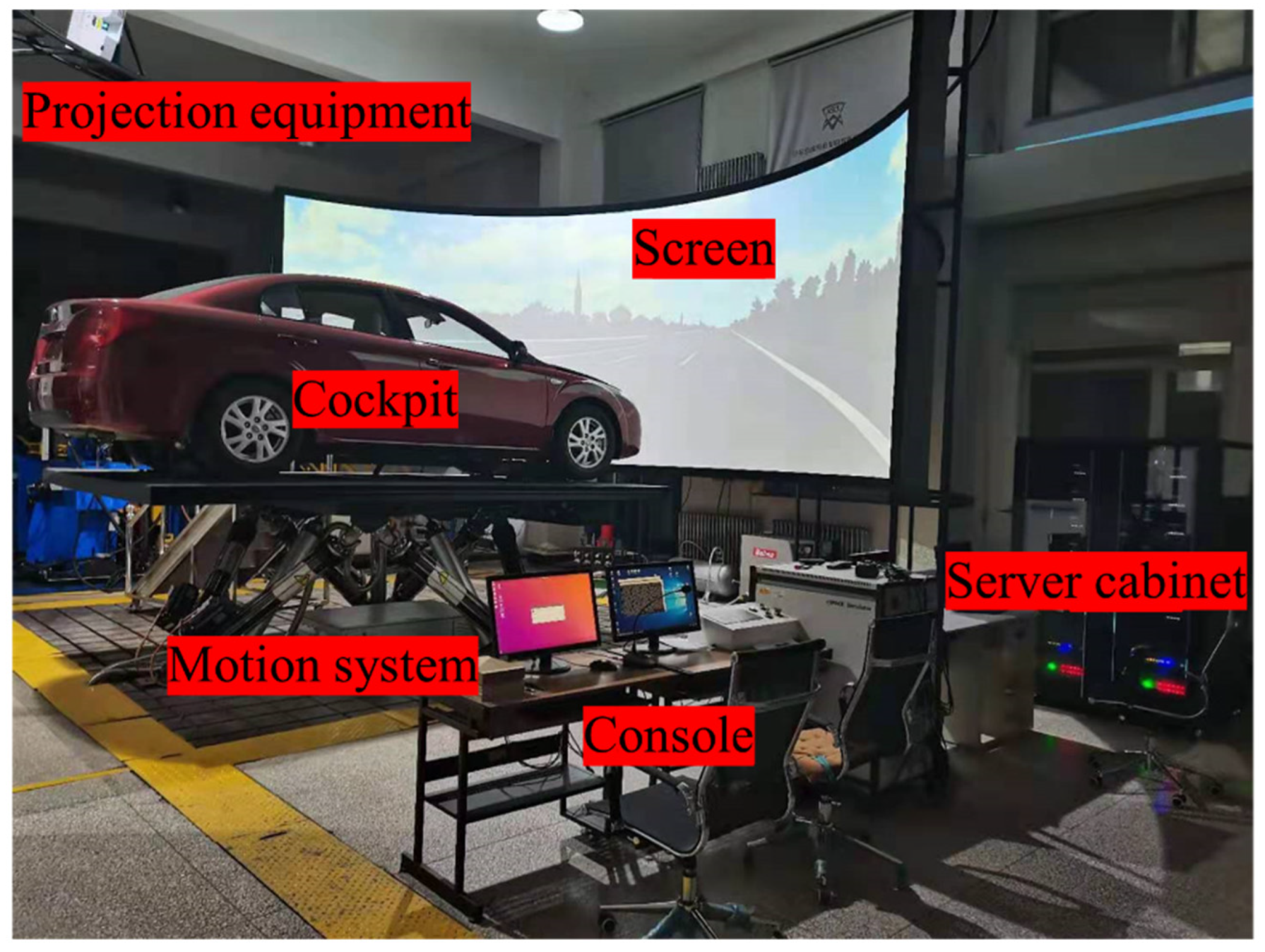
The fuel cell vehicle dynamics model is embedded in the automobile driving simulator to replace the traditional vehicle dynamics model and form a subjective evaluation platform of driveability for fuel cell vehicles. As shown in Figure 10, the fuel cell vehicle dynamics model is used to calculate the dynamic response of the fuel cell vehicles. The projection equipment and screen form a visual system to provide drivers with traffic scenes and visual simulation. The motion system provides the driver with a sense of vehicle motion. The console is used for test control, condition generation and test data recording. The cockpit is used for human–machine interaction.

Figure 10.
Evaluation platform of driveability for fuel cell vehicles.
5. Subjective Evaluation Method of Driveability for Fuel Cell Vehicles
Due to the change in the powertrain system of fuel cell vehicles, the transmission mechanism is relatively simple, which reduces the impact of engine vibration, clutch engagement and shifting. However, the driveability of fuel cell vehicles is different from that of traditional vehicles because of the impact of the dynamic response characteristics, energy management and braking energy recovery of fuel cell engines. According to the characteristics of fuel cell vehicles, the evaluation method of driveability for fuel cell vehicles proposed in this paper includes four subjective evaluation items: starting performance, acceleration performance, uniform speed performance and tip-in/tip-out performance.
5.1. Starting Performance
The evaluation of starting performance of fuel cell vehicles is conducted under three working conditions: starting with a small accelerator pedal opening, starting with a medium accelerator pedal opening, and starting with a large accelerator pedal opening. Specifically, when the vehicle is on a flat and straight road, accelerate to a certain speed with 30%, 50% and 80% accelerator pedal opening. The main evaluation indicators are the starting response, starting feeling, starting jerk and body pitch. The starting response evaluates the time when acceleration is felt after stepping on the accelerator pedal. The starting feeling evaluates whether the vehicle is smooth in the starting process and reflects the vehicle starting acceleration. The starting jerk evaluates the size of the longitudinal jerk felt by the driver during the starting process. The body pitch evaluates the pitch angle and pitch frequency that the driver feels during the starting process.
5.2. Acceleration Performance
The evaluation of the acceleration performance of fuel cell vehicles includes four working conditions: accelerating to 100 km/h at the full accelerator pedal pressing, interval acceleration at the full accelerator pedal pressing, slow accelerator pedal pressing, and sudden accelerator pedal pressing.
- (1)
- Accelerating to 100 km/h at the full accelerator pedal pressing: the driver will step down the accelerator pedal to the bottom to accelerate the fuel cell vehicle from a standstill to 100 km/h.
- (2)
- Interval acceleration at full accelerator pedal pressing: when the accelerator pedal opening is 100%, the driver accelerates in the following speed ranges: 20–60 km/h, 40–80 km/h, 60–100 km/h and 80–120 km/h.
- (3)
- Sudden accelerator pedal pressing: the initial speed is 40 km/h, 60 km/h and 80 km/h. This is followed by sudden acceleration with 30%, 50% and 80% accelerator pedal opening.
- (4)
- Slow accelerator pedal pressing: the initial speed is 40 km/h, 60 km/h and 80 km/h. This is followed by pressing the accelerator to the bottom for about 3 s, 6 s and 9 s, respectively, to accelerate.
The acceleration performance is mainly evaluated from the following four aspects: acceleration feeling, acceleration response, acceleration jerk and body pitch. The acceleration feeling reflects the acceleration of the vehicle and evaluates the feeling of pushing back felt by the driver during acceleration. The acceleration response reflects the time when the driver feels accelerated from pressing the accelerator pedal. The acceleration jerk evaluates the longitudinal jerk of the vehicle felt by the driver during acceleration. The body pitch evaluates whether the driver feels the pitch frequency and angle is appropriate during acceleration.
5.3. Uniform Speed Performance
Fuel cell vehicles are driven at a constant speed of 30 km/h, 50 km/h, 70 km/h, 100 km/h and 120 km/h, respectively. The uniform speed performance is evaluated from two aspects: body shrugging and speed controllability. The body shrugging reflects the anti-jamming ability of the vehicle at a constant speed. The speed controllability reflects whether the driver can easily control the accelerator pedal to maintain a constant speed of the vehicle.
5.4. Tip-In/Tip-Out Performance
The test conditions for the tip-in/tip-out performance of fuel cell vehicles are as follows: the initial speed is 25 km/h or 45 km/h. Then, the vehicles accelerate with 30%, 50% and 80% accelerator pedal opening, respectively, and the accelerator pedal is released after 1.5 s.
The tip-in/tip-out performance is mainly evaluated from two aspects: speed response and longitudinal jerk. The speed response reflects the time from tip-in/tip-out to acceleration or deceleration. The longitudinal jerk evaluates the longitudinal jerk of the vehicle felt by the driver during the tip-in/tip-out process.
6. Results and Discussion
This paper evaluates the drivability of fuel cell vehicles with a changed powertrain system compared with traditional vehicles. Therefore, this paper adopts a seven-point subjective evaluation scoring method, as shown in Table 1. It can be seen that four points are taken as the dividing line of evaluation, and the drivability of the original traditional vehicles is taken as the benchmark of the dividing line.

Table 1.
Subjective evaluation scoring scale.
Eight evaluators of different genders and driving experience are selected to score the fuel cell vehicle, and the scores are averaged to obtain the final scores. The scores are as follows.
6.1. Starting Performance Results and Analysis
The subjective evaluation results of starting performance are shown in Figure 11. The overall score is good under each condition except the starting feeling. The starting feeling score is low under 30% and 50% accelerator pedal opening, which indicates that the starting feeling of the fuel cell vehicle is not good under the small and the medium accelerator pedal opening. This may be due to insufficient discharge of the fuel cell during starting or the vehicle energy management restriction. The body pitch score is low when the accelerator pedal opening is 80%, which indicates that the body control is not ideal with a large accelerator pedal opening.
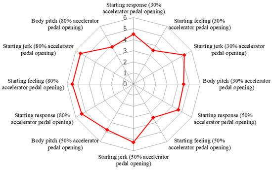
Figure 11.
Subjective evaluation results of starting performance.
6.2. Acceleration Performance Results and Analysis
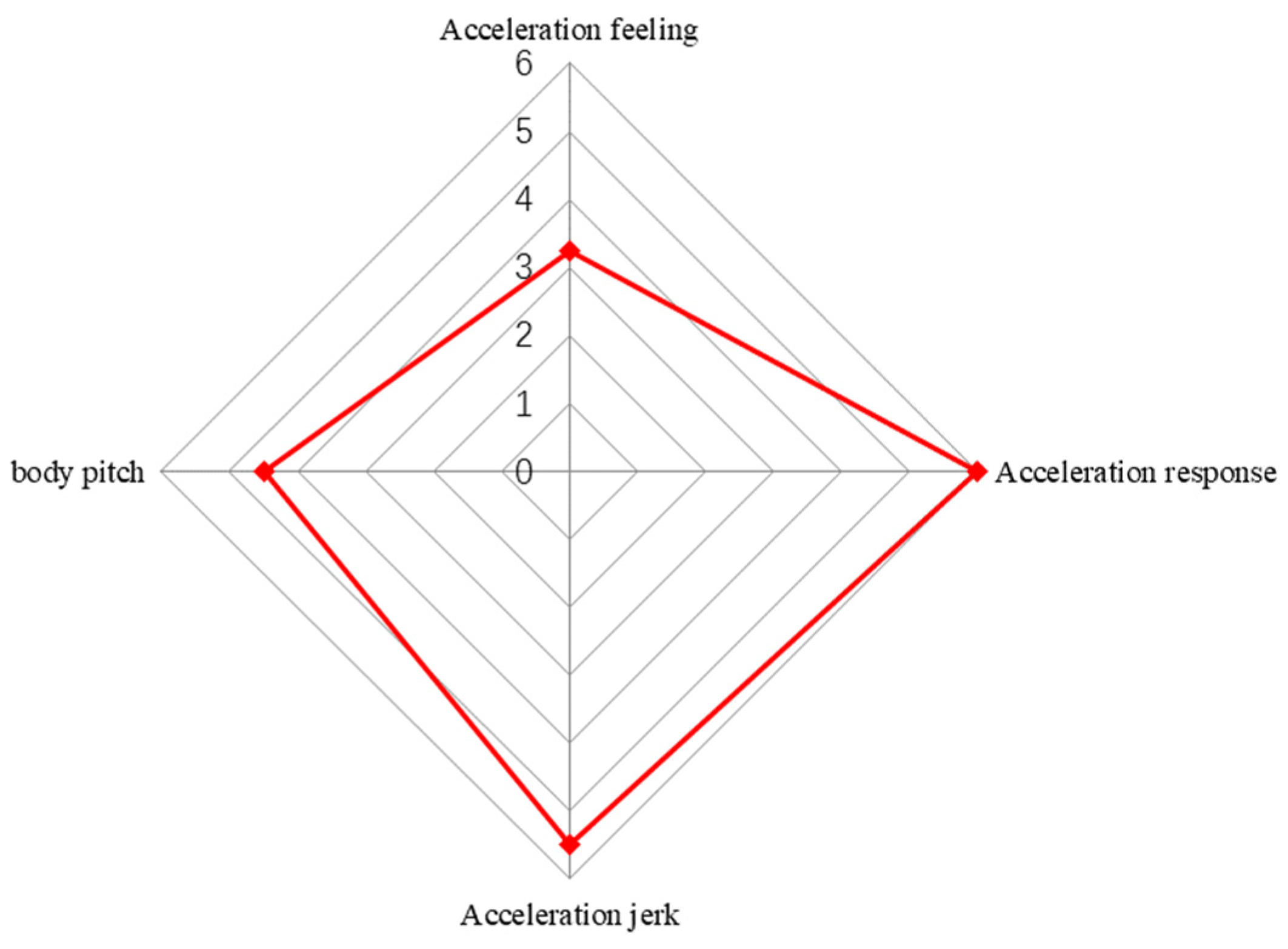
The subjective evaluation results of accelerating to 100 km/h at full accelerator pedal pressing are shown in Figure 12. The scores of the acceleration response, acceleration jerk and body pitch are all 5–6 points, indicating that the acceleration performance is good. However, the score of acceleration feeling is 3 points, which indicates that the acceleration felt by the driver is small.
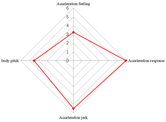
Figure 12.
Subjective evaluation results of accelerating to 100 km/h at full accelerator pedal pressing.
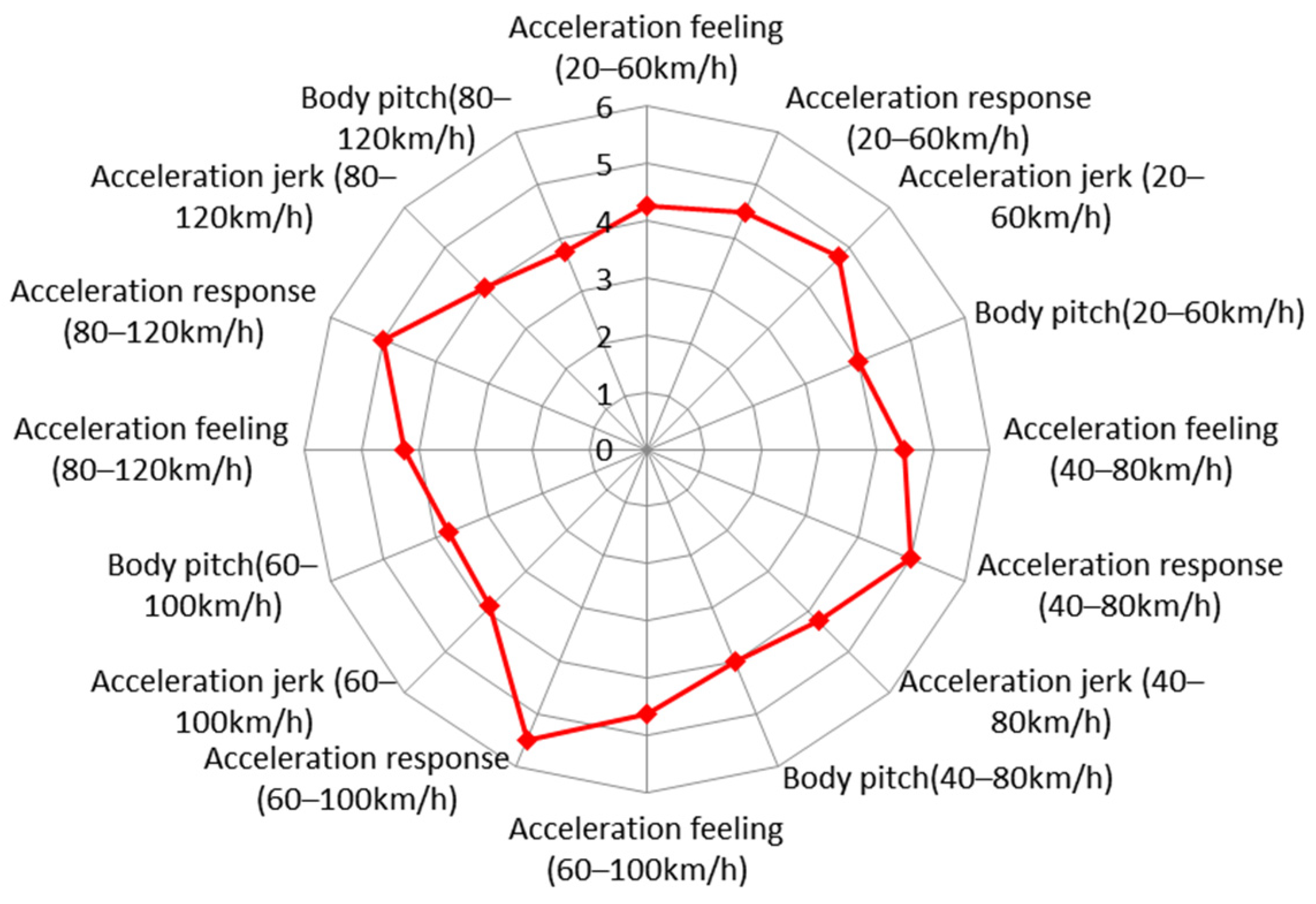
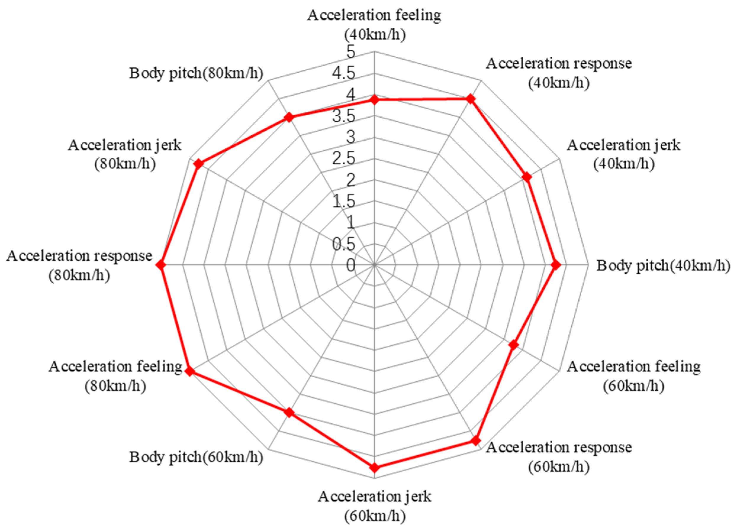
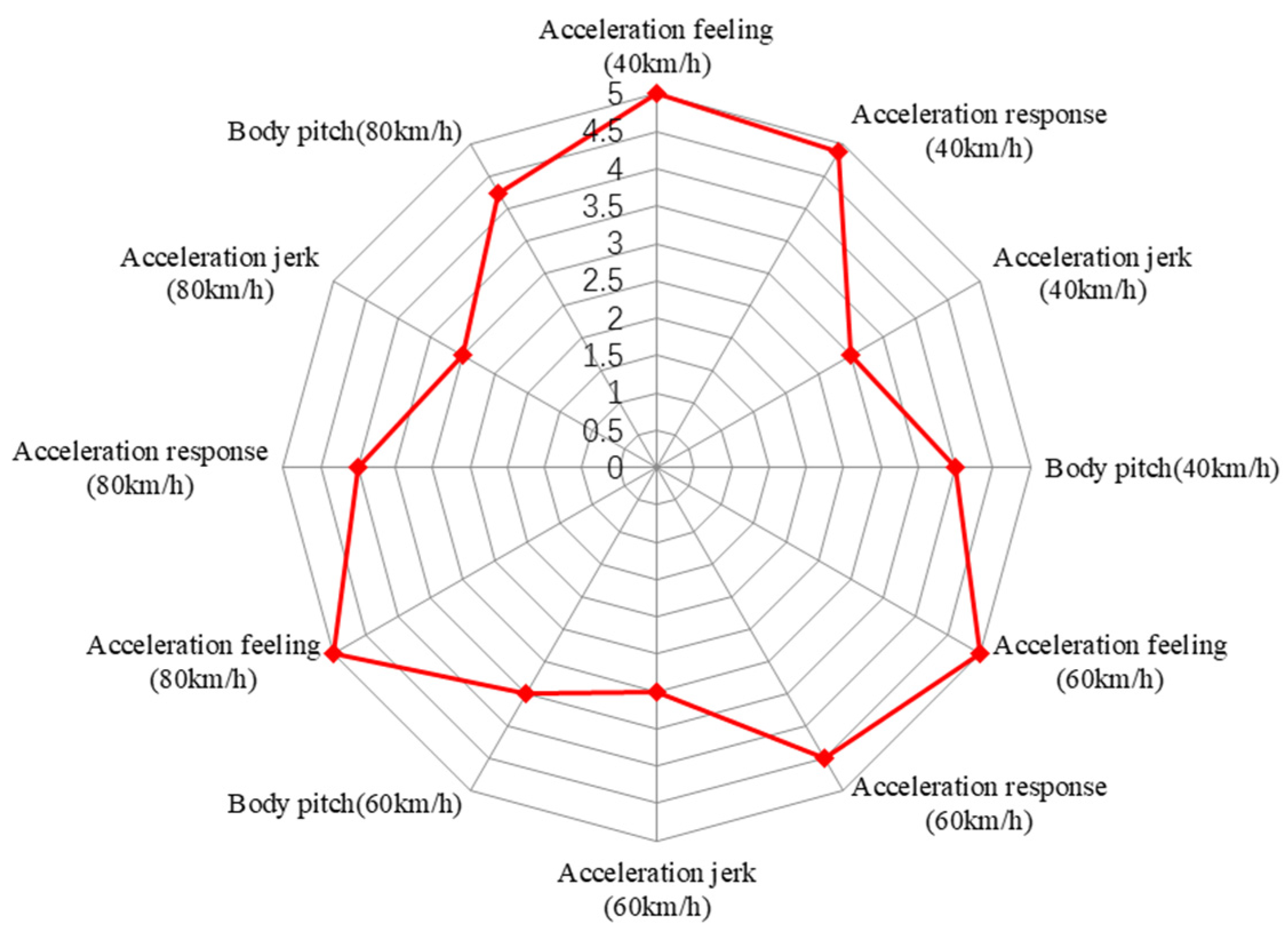
The subjective evaluation results of interval acceleration at full accelerator pedal pressing are shown in Figure 13. The overall score of the fuel cell vehicle is high, basically above 4 points. In terms of acceleration response, the fuel cell vehicle is superior to the traditional vehicle in all speed ranges, especially in the 60–100 km/h range. In terms of acceleration feeling, the fuel cell vehicle is better than the traditional vehicle. The body pitch score is relatively low, which indicates that the body control of the fuel cell vehicle is weak. In terms of the acceleration jerk, there is little difference between them.
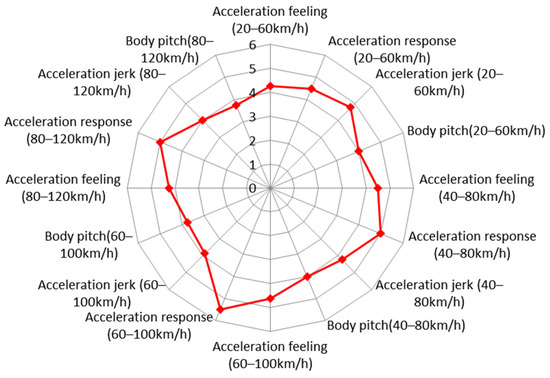
Figure 13.
Subjective evaluation results of interval acceleration at the full accelerator pedal pressing.
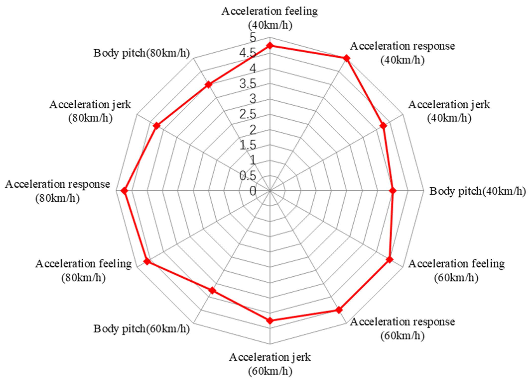
The subjective evaluation results of sudden accelerator pedal pressing to 30% opening are shown in Figure 14. The score of each condition is high, which indicates that the fuel cell vehicle performs better than the traditional vehicle in acceleration response, acceleration jerk, body pitch and other aspects.

Figure 14.
Subjective evaluation results of sudden accelerator pedal pressing to 30% opening.
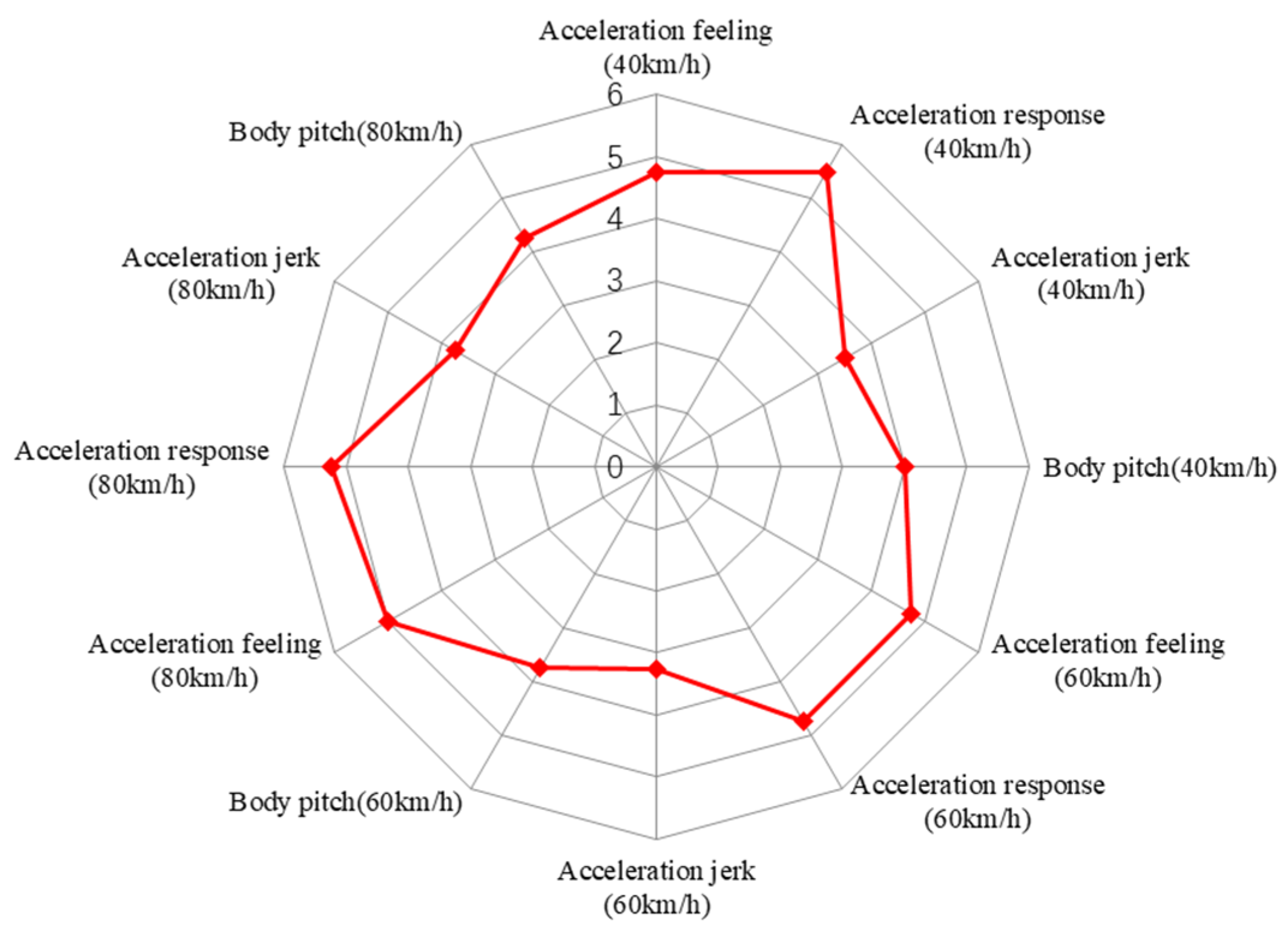
The subjective evaluation results of sudden accelerator pedal pressing to 50% opening are shown in Figure 15. The subjective scores of the acceleration feeling, acceleration response and acceleration jerk are high under each speed condition. In terms of body pitch, the score of the fuel cell vehicle is relatively low.
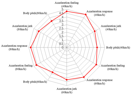
Figure 15.
Subjective evaluation results of sudden accelerator pedal pressing to 50% opening.
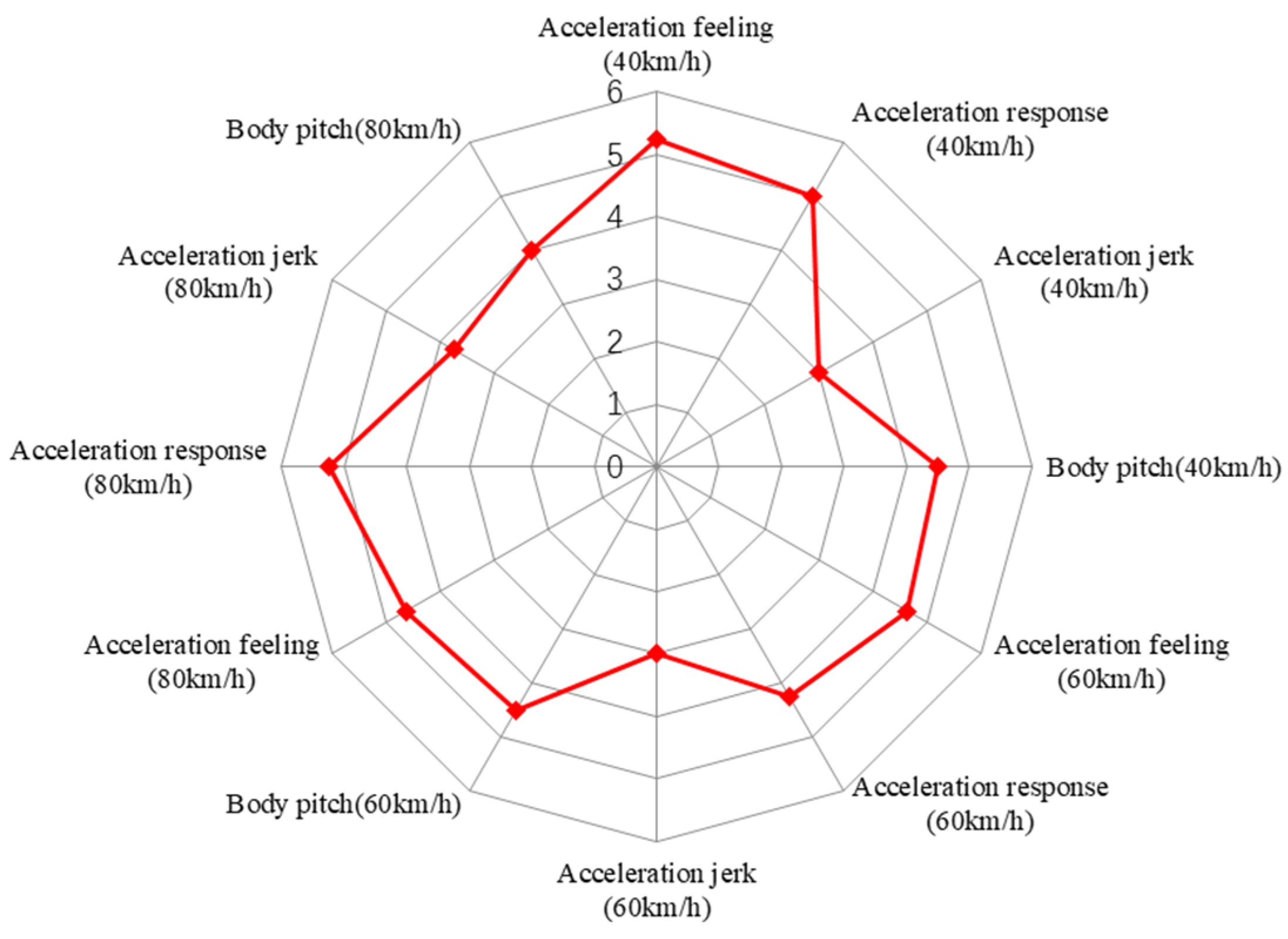
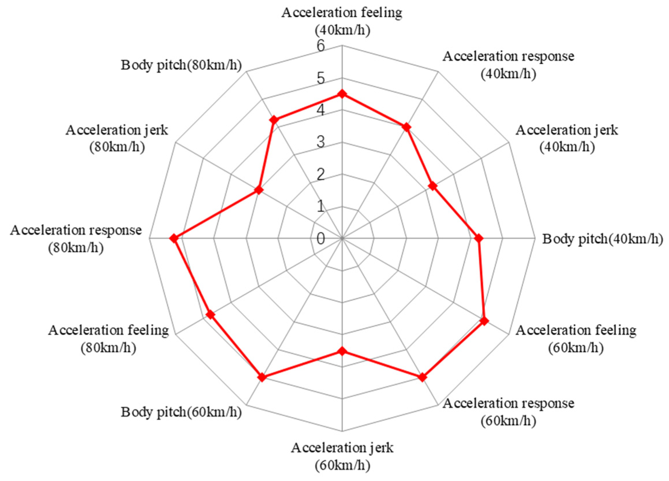
The subjective evaluation results of sudden accelerator pedal pressing to 80% opening are shown in Figure 16. The subjective scores of the acceleration feeling and acceleration response at each speed condition are high while sudden accelerator pedal pressing to 80%. In terms of body pitch, the fuel cell vehicle is almost the same as the traditional vehicle. However, in terms of acceleration jerk, the subjective score of the fuel cell vehicle is low, which indicates that the jerk felt by the driver is large.
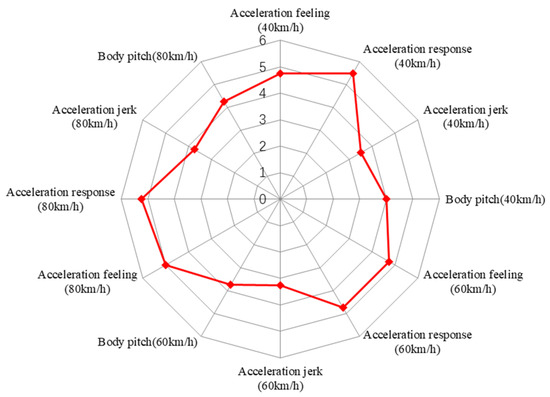
Figure 16.
Subjective evaluation results of sudden accelerator pedal pressing to 80% opening.
The subjective evaluation results of slow accelerator pedal pressing for 3 s, 6 s and 9 s are shown in Figure 17, Figure 18 and Figure 19. It can be seen that the subjective score under slow accelerator pedal pressing is unbalanced. The acceleration response score is high, but the acceleration jerk score is low. This is closely related to the control logic of the vehicle controller.
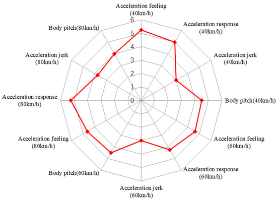
Figure 17.
Subjective evaluation results of slow accelerator pedal pressing for 3 s.

Figure 18.
Subjective evaluation results of slow accelerator pedal pressing for 6 s.
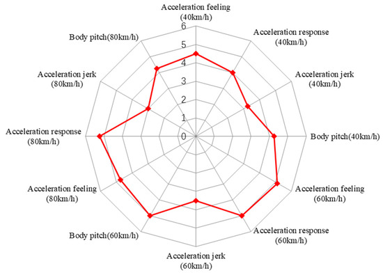
Figure 19.
Subjective evaluation results of slow accelerator pedal pressing for 9 s.
6.3. Uniform Speed Performance Results and Analysis
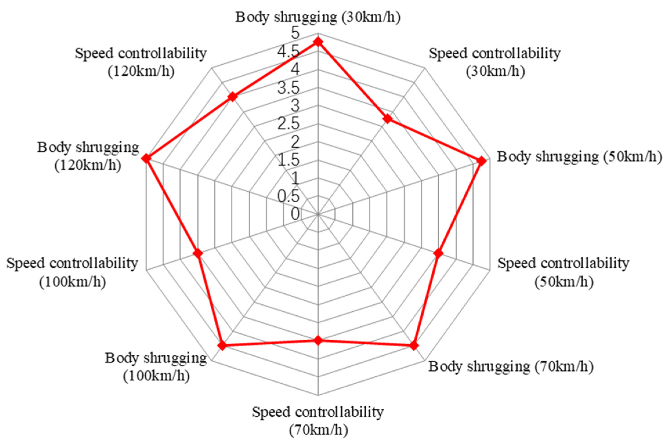
The subjective evaluation results of uniform speed performance are shown in Figure 20. The body shrugging score is high at each speed, which indicates that the fuel cell vehicle has a strong anti-interference ability under constant speed. However, the speed controllability score is slightly low, which indicates that the torque control is poor.
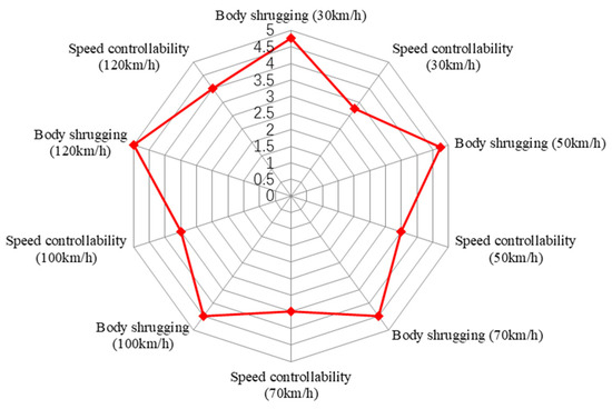
Figure 20.
Subjective evaluation results of uniform speed performance.
6.4. Tip-In/Tip-Out Performance Results and Analysis
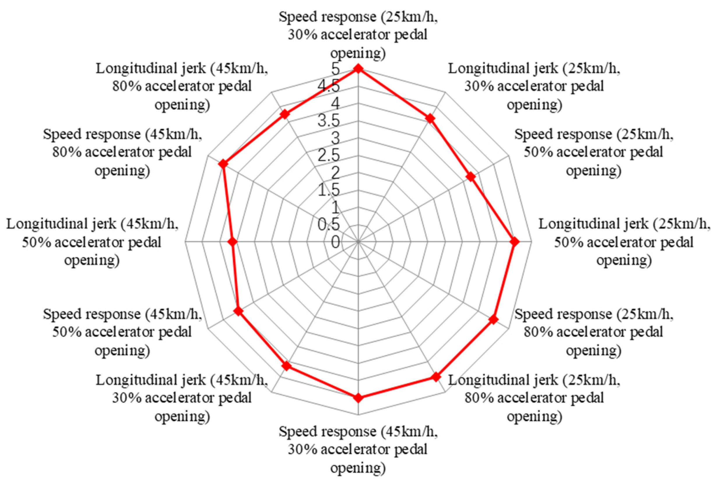
The subjective evaluation results of tip-in/tip-out performance are shown in Figure 21. The speed response scores are high, which indicates that the vehicle controller has a good response to the demand for rapid torque change. The longitudinal jerk score is slightly low, which indicates that the longitudinal jerk of the vehicle felt by the driver is relatively large.
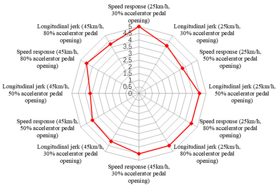
Figure 21.
Subjective evaluation results of tip-in/tip-out performance.
7. Conclusions
In this paper, a real-time model of the fuel cell vehicle powertrain system was established and a virtual subjective evaluation platform for fuel cell vehicles was built. And subjective evaluation was conducted on the virtual prototype of a fuel cell vehicle according to the subjective evaluation method mentioned in this paper. The main conclusions are as follows:
- The virtual subjective evaluation of driveability for fuel cell vehicles requires the high-fidelity vehicle dynamics model and real-time fuel cell powertrain system model, so as to dynamically calculate the main responses of vehicle driveability concerns such as acceleration and body pitch.
- An evaluation method for the driveability of fuel cell vehicles was proposed, including the starting performance, acceleration performance, uniform speed performance and tip-in/tip-out performance. The evaluation indicator system was composed of acceleration response, acceleration jerk, body pitch, etc.
- The virtual subjective evaluation platform for fuel cell vehicles was used to evaluate the vehicle according to the evaluation method proposed, which verified the platform and evaluation method.
- For the subjective evaluation of the driveability of fuel cell vehicles, it is necessary to conduct field tests on real vehicles in subsequent research to obtain specific test results. Meanwhile, it is also necessary to select as many evaluators from different regions and with different driving experience as possible to complete subjective evaluation tests on fuel cell vehicles to obtain more accurate evaluation results.
Author Contributions
Conceptualization, J.Z.; methodology, J.Z.; software, H.Z. and C.D.; investigation, W.H., B.Z. and G.X.; writing—original draft, J.Z., H.Z. and Z.-H.Z.; writing—review and editing, C.D. and W.H.; data curation, Z.-H.Z.; formal analysis, B.Z. and G.X.; visualization, B.Z. and G.X. All authors have read and agreed to the published version of the manuscript.
Funding
This work has been funded by the National Key Research and Development Program of China (grant number: 2018YFB1502702).
Data Availability Statement
Data are contained within the article.
Conflicts of Interest
Authors Wei Huang, Baoli Zhu and Guangjian Xu were employed by the company China National Heavy Duty Truck Group Co., Ltd. The remaining authors declare that the research was conducted in the absence of any commercial or financial relationships that could be construed as a potential conflict of interest.
References
- Gurz, M.; Baltacioglu, E.; Hames, Y.; Kaya, K. The meeting of hydrogen and automotive: A review. Int. J. Hydrogen Energy 2017, 42, 23334–23346. [Google Scholar] [CrossRef]
- Raut, K.; Shendge, A.; Chaudhari, J.; Lamba, R.; Alshammari, N.F. Modeling and simulation of photovoltaic powered battery-supercapacitor hybrid energy storage system for electric vehicles. J. Energy Storage 2024, 82, 19. [Google Scholar] [CrossRef]
- Malozyomov, B.V.; Martyushev, N.V.; Kukartsev, V.A.; Kukartsev, V.V.; Tynchenko, S.V.; Klyuev, R.V.; Zagorodnii, N.A.; Tynchenko, Y.A. Study of Supercapacitors Built in the Start-Up System of the Main Diesel Locomotive. Energies 2023, 16, 3909. [Google Scholar] [CrossRef]
- List, H.O.; Schoeggl, P. Objective Evaluation of Vehicle Driveability; SAE Technical Paper; SAE International: Warrendale, PA, USA, 1998. [Google Scholar] [CrossRef]
- Schoeggl, P.; Ramschak, E. Vehicle Driveability Assessment using Neural Networks for Development, Calibration and Quality Tests; SAE Technical Paper; SAE International: Warrendale, PA, USA, 2000. [Google Scholar] [CrossRef]
- Hayat, O.; Lebrun, M.; Domingues, E. Powertrain Driveability Evaluation: Analysis and Simplification of Dynamic Models; SAE transactions; SAE International: Warrendale, PA, USA, 2003; pp. 569–578. Available online: https://www.jstor.org/stable/44699714 (accessed on 1 November 2020).
- Zehetner, J.; Schöggl, P.; Dank, M.; Meitz, K. Simulation of Driveability in Real-Time; SAE Technical Paper; SAE International: Warrendale, PA, USA, 2009. [Google Scholar] [CrossRef]
- Shin, C.W.; Kim, H.; Kim, M.K.; Lim, W.; Cha, S.W. Development of an evaluation method for quantitative driveability in heavy-duty vehicles. J. Mech. Sci. Technol. 2014, 28, 1615–1621. [Google Scholar] [CrossRef]
- Walters, T.L.; Shaw, P.; Kumar, M.M.; Hoop, J. Analysis Lead Drivability Assessment; SAE Technical Paper; SAE International: Warrendale, PA, USA, 2015. [Google Scholar] [CrossRef]
- Lakshmanan, S.; Palaniappan, A.; Chekuri, V. Methodology for Evaluation of Drivability Attributes in Commercial Vehicle; SAE Technical Paper; SAE International: Warrendale, PA, USA, 2015. [Google Scholar] [CrossRef]
- Castellazzi, L.; Tonoli, A.; Amati, N.; Galliera, E. A study on the role of powertrain system dynamics on vehicle driveability. Veh. Syst. Dyn. 2017, 55, 1012–1028. [Google Scholar] [CrossRef]
- Liu, H.; Huang, W. The Research of Drivability Evaluation Index and Quantitative Method; SAE Technical Paper; SAE International: Warrendale, PA, USA, 2016. [Google Scholar] [CrossRef]
- Chandrasekaran, K.; Rao, N.; Palraj, S.; Kurella, C.; noohu Lebbai, M. Objective Drivability Evaluation on Compact SUV and Comparison with Subjective Drivability; SAE Technical Paper; SAE International: Warrendale, PA, USA, 2017. [Google Scholar] [CrossRef]
- Huang, W.; Liu, H.J.; Ma, Y.F. Drivability evaluation model using principal component analysis and optimized extreme learning machine. J. Vib. Control 2019, 25, 2274–2281. [Google Scholar] [CrossRef]
- Guse, D.; Heusch, C.; Pischinger, S.; Tegelkamp, S.; Schmidt, C.; Roehrich, H.; Nijs, M.; Scharf, J. Objectified Drivability Evaluation and Classification of Passenger Vehicles in Automated Longitudinal Vehicle Drive Maneuvers with Engine Load Changes; SAE Technical Paper; SAE International: Warrendale, PA, USA, 2019. [Google Scholar] [CrossRef]
- Zhou, W.; Guo, X.; Pei, X.; Zhang, C.; Yan, J.; Xia, J. Objective evaluation of drivability in passenger cars with dual-clutch transmission: A case study of static gearshift condition. Math. Probl. Eng. 2020, 2020, 2061083. [Google Scholar] [CrossRef]
- Huang, W.; Liu, H.J. Application of fuzzy dynamic weights drivability evaluation model in tip-in condition. J. Vib. Control 2019, 25, 739–747. [Google Scholar] [CrossRef]
- Zhou, W.; Guo, X.; Zhang, C.; Xia, J.; Yan, J. Evaluation Index System and Empire Analysis of Drivability for Passenger Car Powertrain; SAE Technical Paper; SAE International: Warrendale, PA, USA, 2021. [Google Scholar] [CrossRef]
- Zhou, W.; Guo, X.X.; Zhang, C.C.; Yan, J.; Xia, J.L. A novel objective evaluation method of drivability for passenger cars considering subjective and objective consistency. Proc. Inst. Mech. Eng. Part D-J. Automob. Eng. 2023, 237, 607–621. [Google Scholar] [CrossRef]
- Wei, X.; Pisu, P.; Rizzoni, G.; Yurkovich, S. Dynamic modeling of a hybrid electric drivetrain for fuel economy, performance and driveability evaluations. In Proceedings of the ASME International Mechanical Engineering Congress and Exposition, Washington, DC, USA, 15–21 November 2003; pp. 443–450. [Google Scholar] [CrossRef]
- Yang, J.; Guo, W.; Zhang, X. The Research on the Subjective and Objective Drivability Evaluation and Analysis of PHEV Passenger Car. In Proceedings of China SAE Congress 2021: Selected Papers; Springer: Berlin/Heidelberg, Germany, 2022; pp. 1124–1136. [Google Scholar]
- Louback, E.; Machado, F.; Bruck, L.; Kollmeyer, P.J.; Emadi, A. Real-Time Performance and Driveability Analysis of a Clutchless Multi-Speed Gearbox for Battery Electric Vehicle Applications. In Proceedings of the 2022 IEEE Transportation Electrification Conference & Expo (ITEC), Anaheim, CA, USA, 15–17 June 2022. [Google Scholar] [CrossRef]
- Domijanic, M.; Hirz, M. Simulation Model for Drivability Assessment and Optimization of Hybrid Drive Trains. Sci. Tech. 2021, 20, 37–44. [Google Scholar] [CrossRef]
- Al-Aawar, N.; Arkadan, A.A. Driveability Optimization of HEV Powertrain. In Proceedings of the International Symposium of Applied-Computational-Electromagnetics-Society (ACES), Miami, FL, USA, 14–18 April 2019. [Google Scholar]
- Jauch, C.; Tamilarasan, S.; Bovee, K.; Güvenc, L.; Rizzoni, G. Modeling for drivability and drivability improving control of HEV. Control Eng. Pract. 2018, 70, 50–62. [Google Scholar] [CrossRef]
- Huang, X. A Fuzzy Evaluation Method for the Drivability of New Energy Vehicles Based on Similarity. J. Phys. Conf. Ser. 2022, 2218, 012066. [Google Scholar] [CrossRef]
- Barroso, D.G.L.; Emadi, A.; Bruck, L. Driver-in-the-Loop Drivability and Energy Efficiency Analysis of Regenerative Braking Strategies for Electric Vehicles; SAE Technical Paper; SAE transactions; SAE International: Warrendale, PA, USA, 2023. [Google Scholar] [CrossRef]
- AVL LIST GmbH. Cruise M Manual, Version 2019 R1; AVL LIST GmbH: Graz, Austria, 2019.
- Guan, X.; Duan, C.G.; Zheng, L.L.; Zhan, J.; Tian, L.; Bao, H. A high fidelity driving feeling real-time dynamic steering system model. In Proceedings of the 24th Symposium of the International-Association-for-Vehicle-System-Dynamics (IAVSD), Graz, Austria, 17–21 August 2015; pp. 779–788. [Google Scholar]
- Mathworks Inc. Matlab User’s Manual; Mathworks Inc.: Natick, MA, USA, 2016. [Google Scholar]


Disclaimer/Publisher’s Note: The statements, opinions and data contained in all publications are solely those of the individual author(s) and contributor(s) and not of MDPI and/or the editor(s). MDPI and/or the editor(s) disclaim responsibility for any injury to people or property resulting from any ideas, methods, instructions or products referred to in the content. |
© 2024 by the authors. Licensee MDPI, Basel, Switzerland. This article is an open access article distributed under the terms and conditions of the Creative Commons Attribution (CC BY) license (https://creativecommons.org/licenses/by/4.0/).