
Development of a Hydrogen Fuel Cell Prototype Vehicle Supported by Artificial Intelligence for Green Urban Transport


Abstract
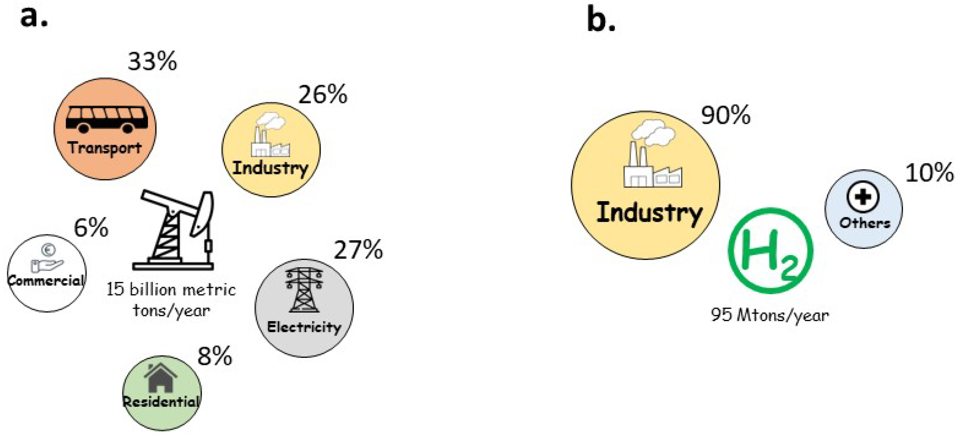
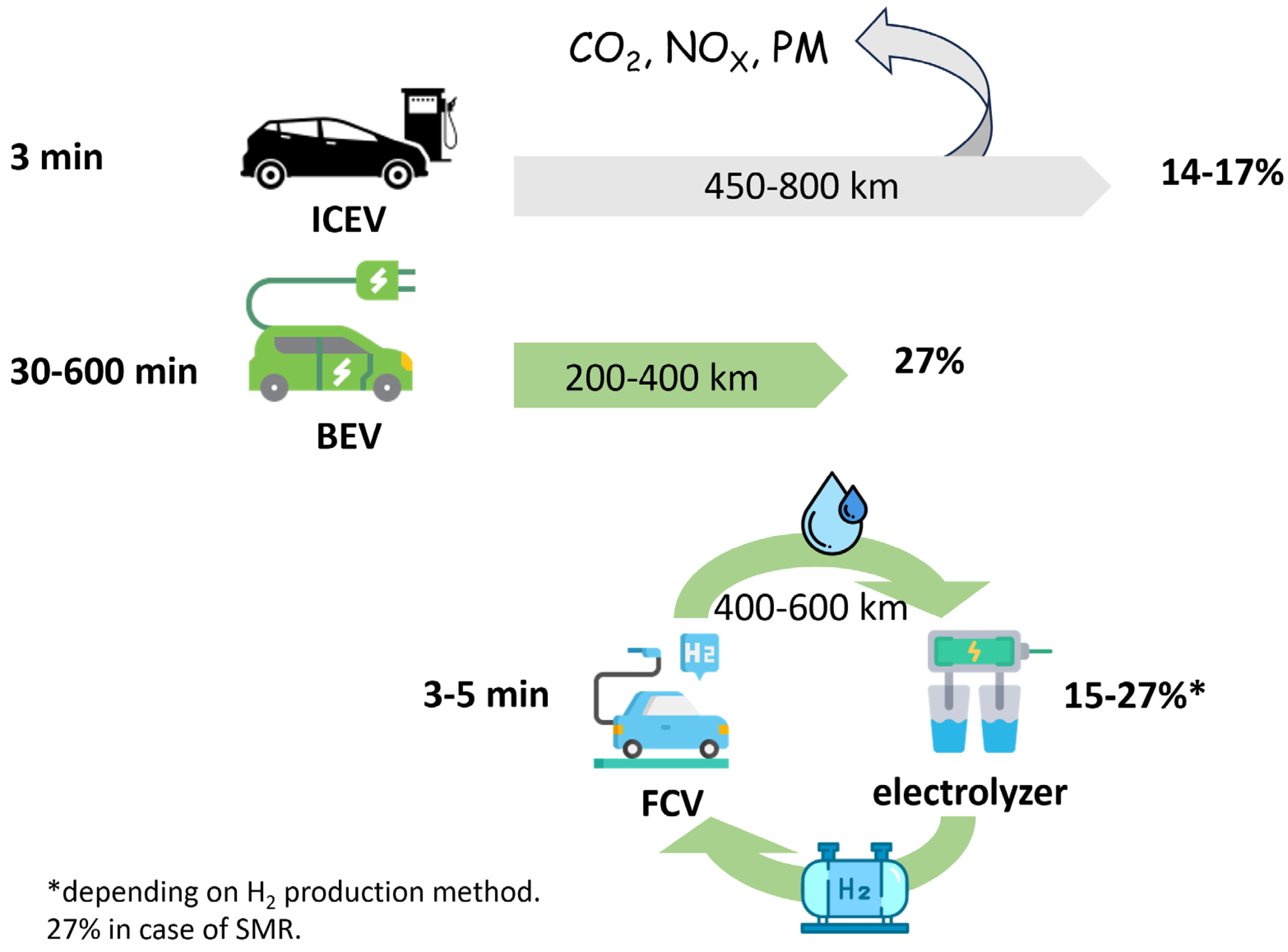
1. Background
2. Design Principles and Methods
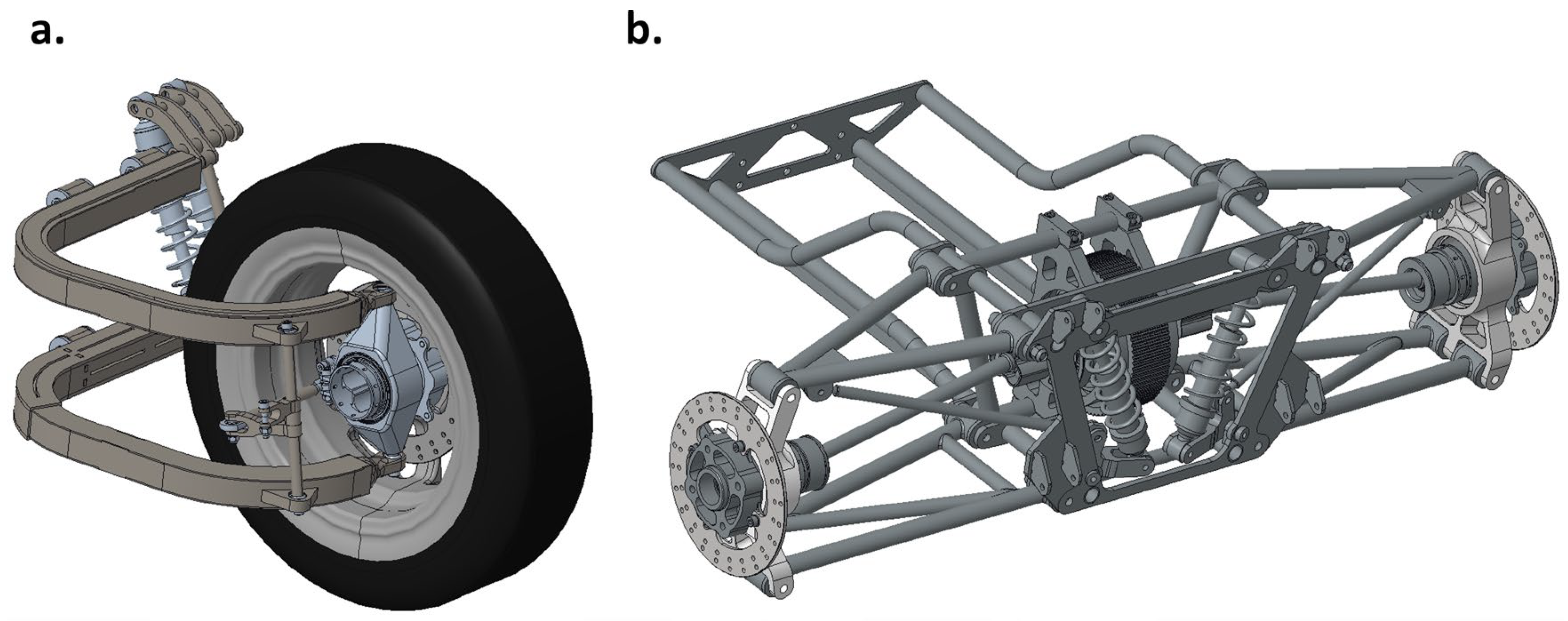
2.1. Design Principles for Main Parts
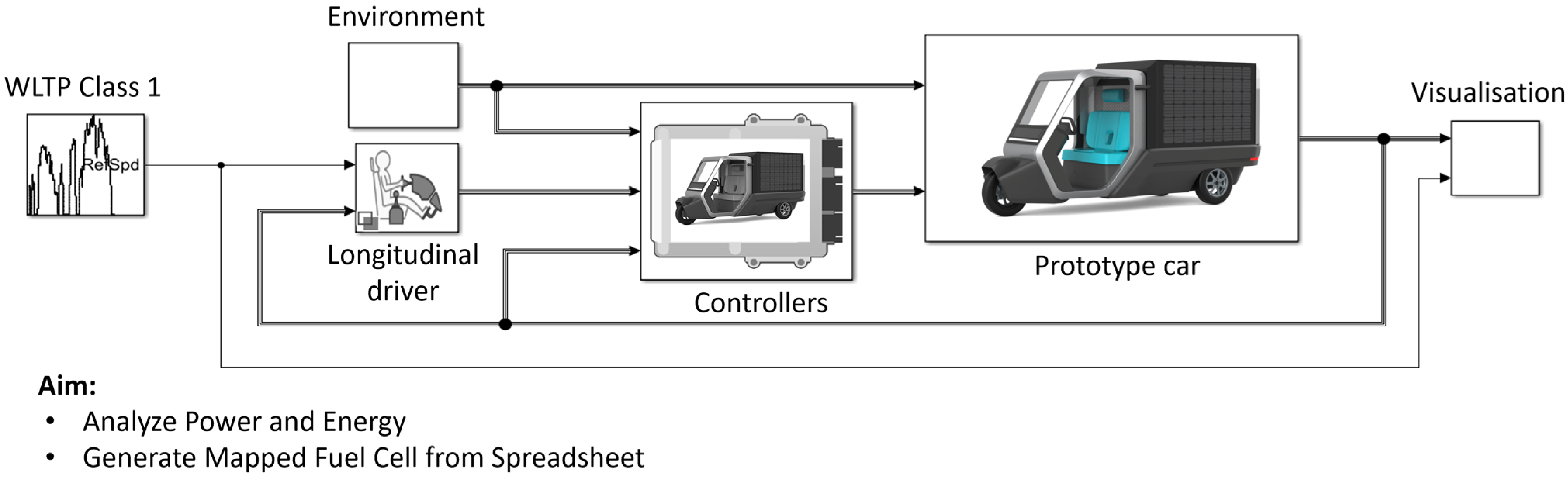
2.2. Artificial Intelligence-Driven Simulation Environment
3. Results and Discussion
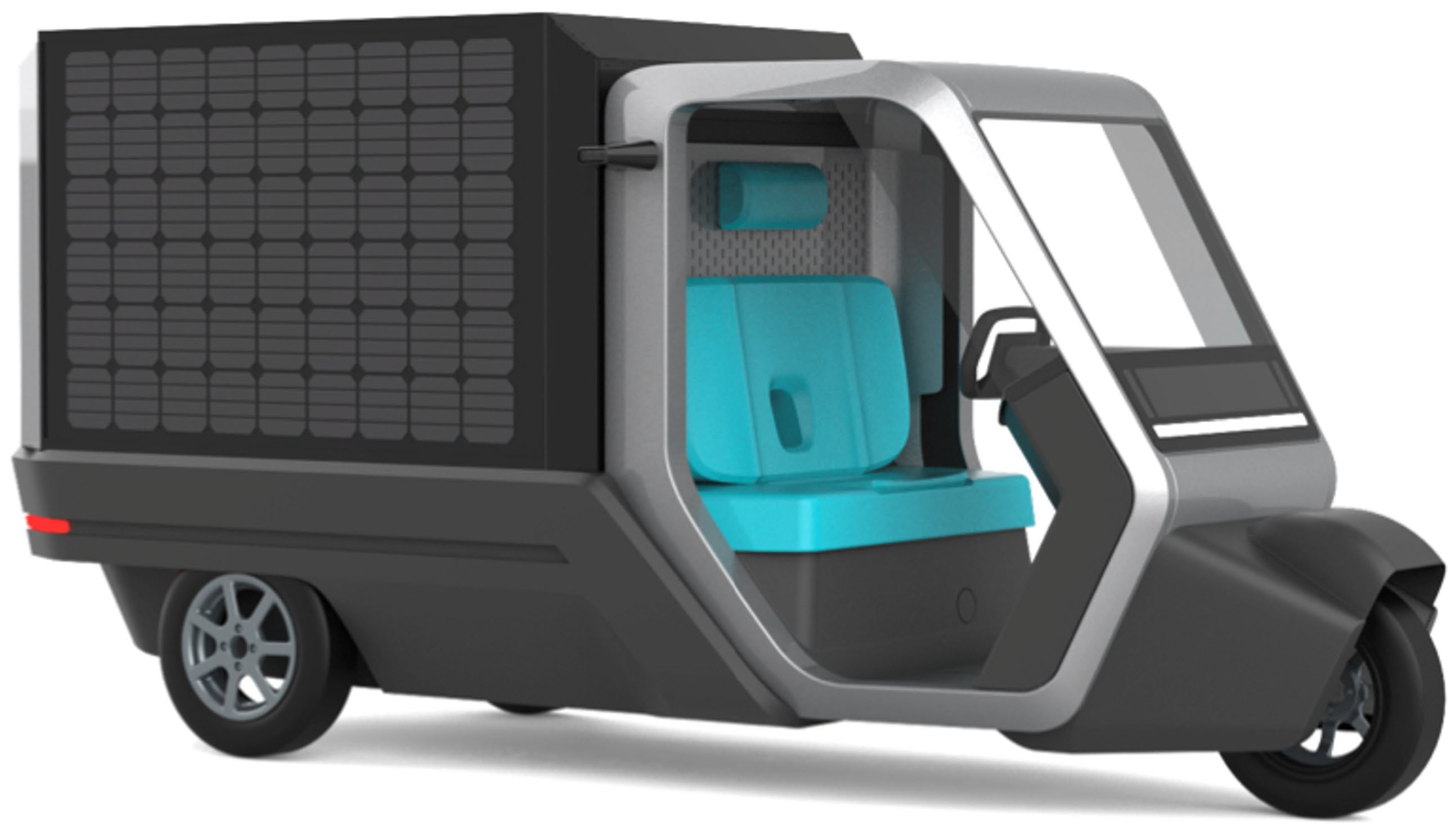
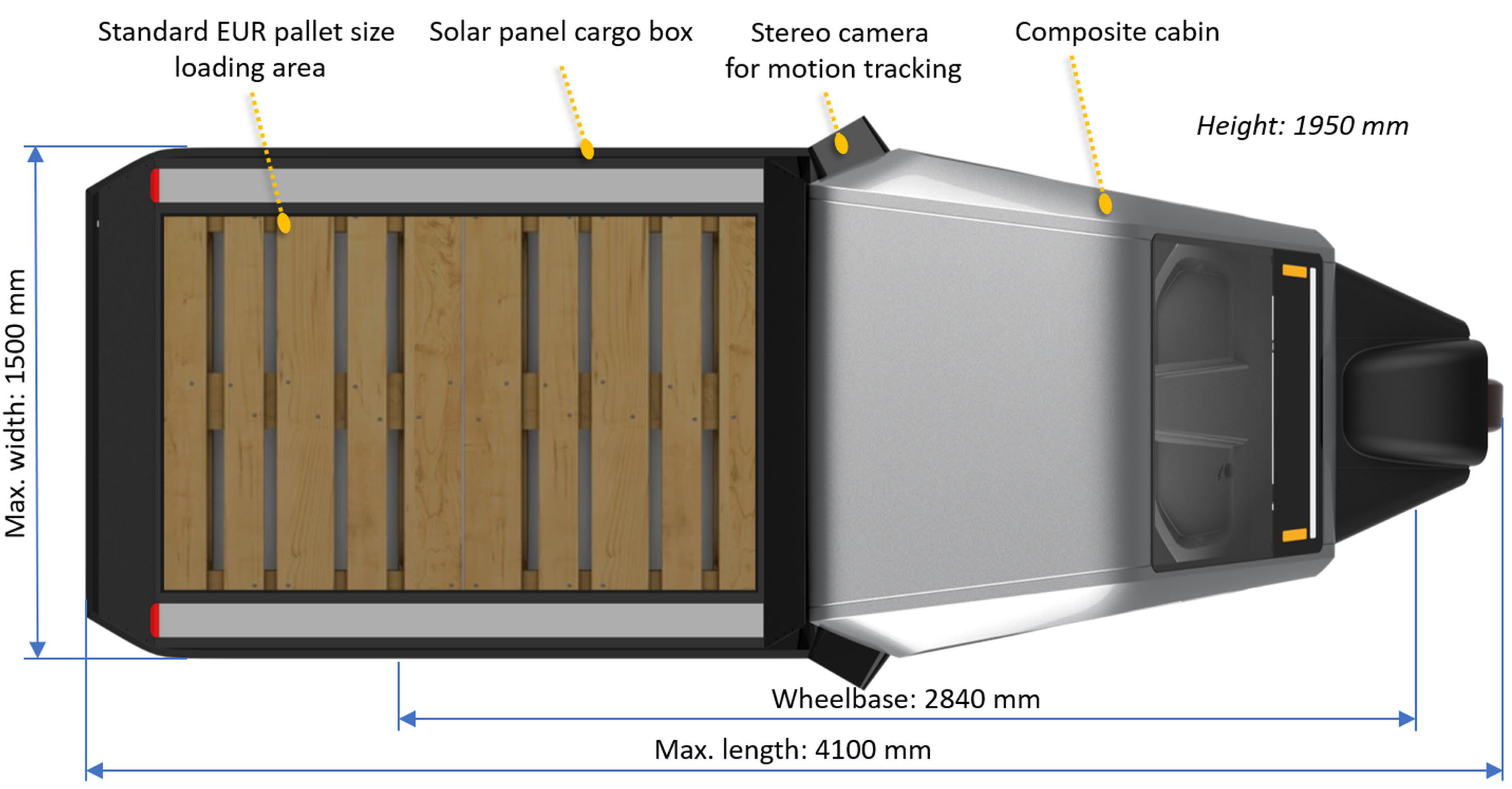
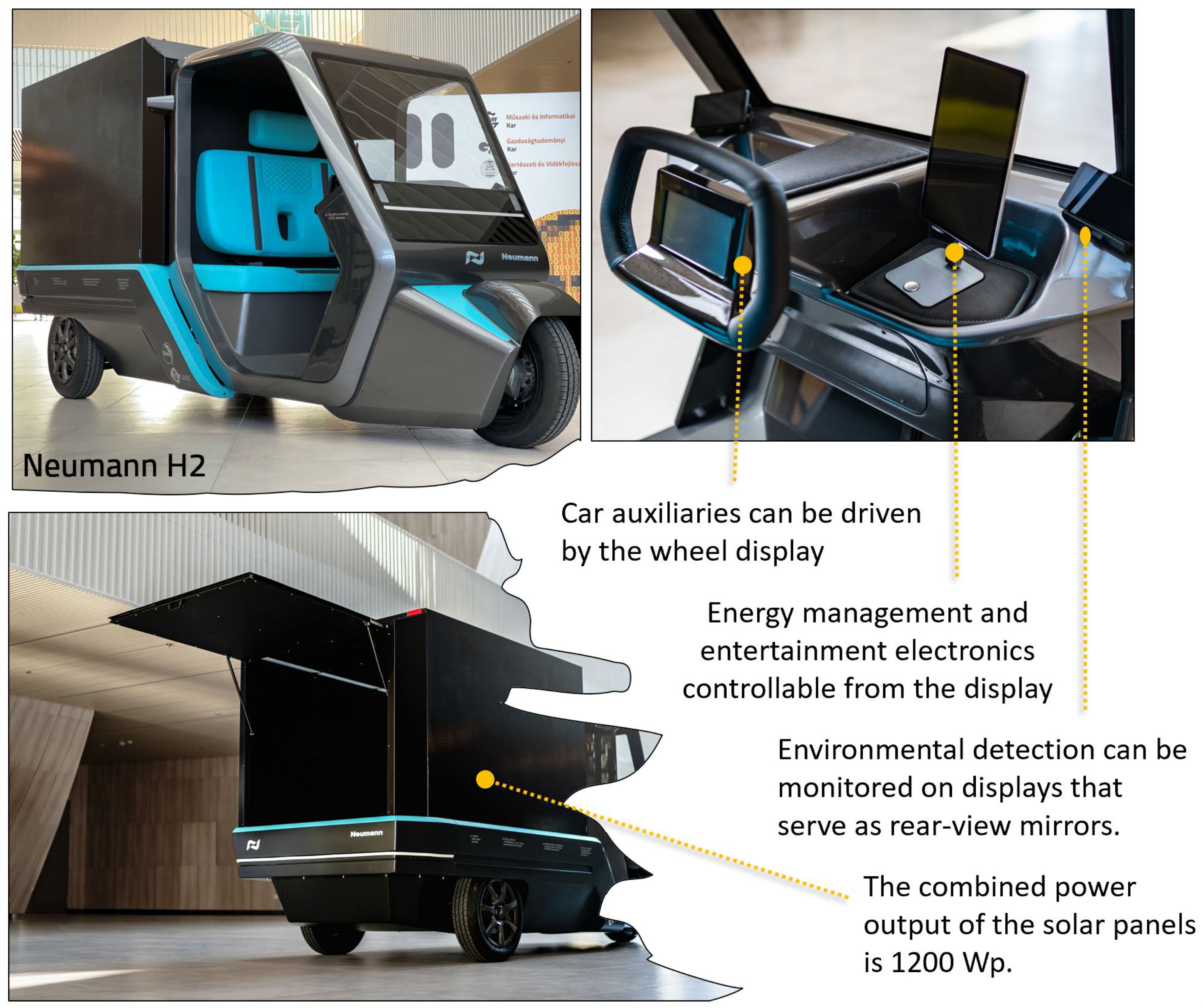
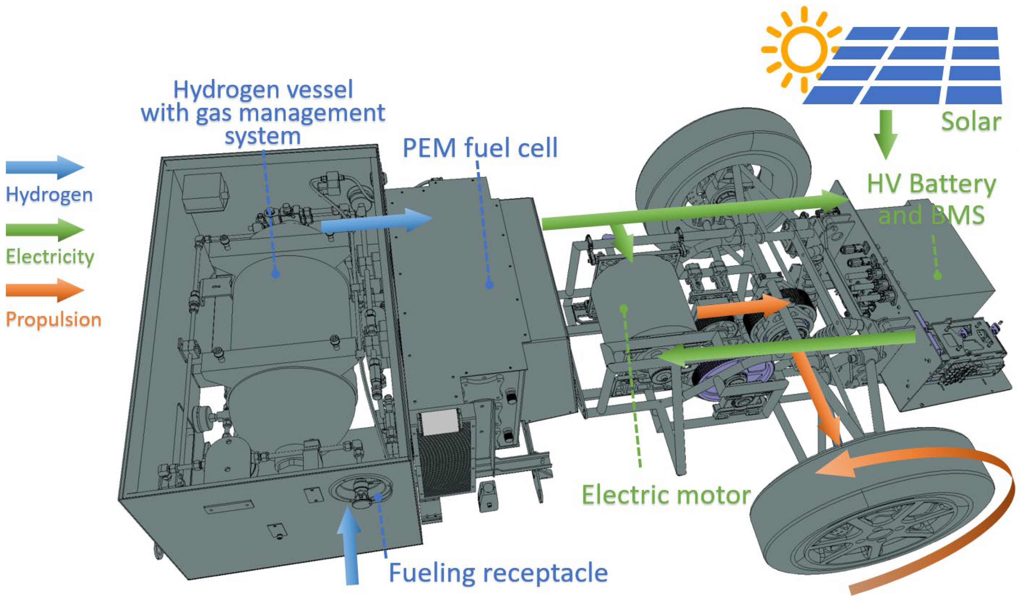
3.1. Structure of the Prototype
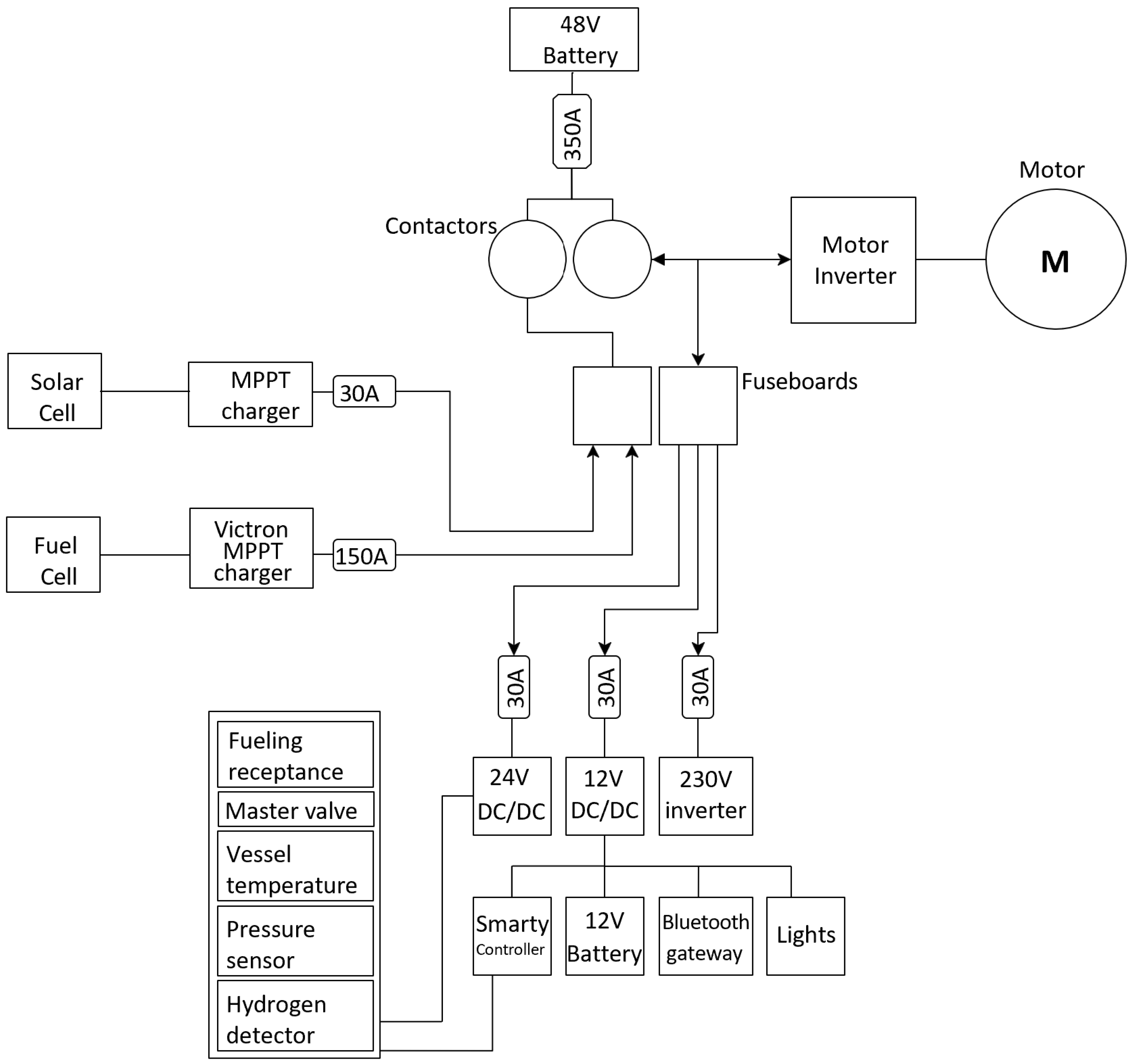
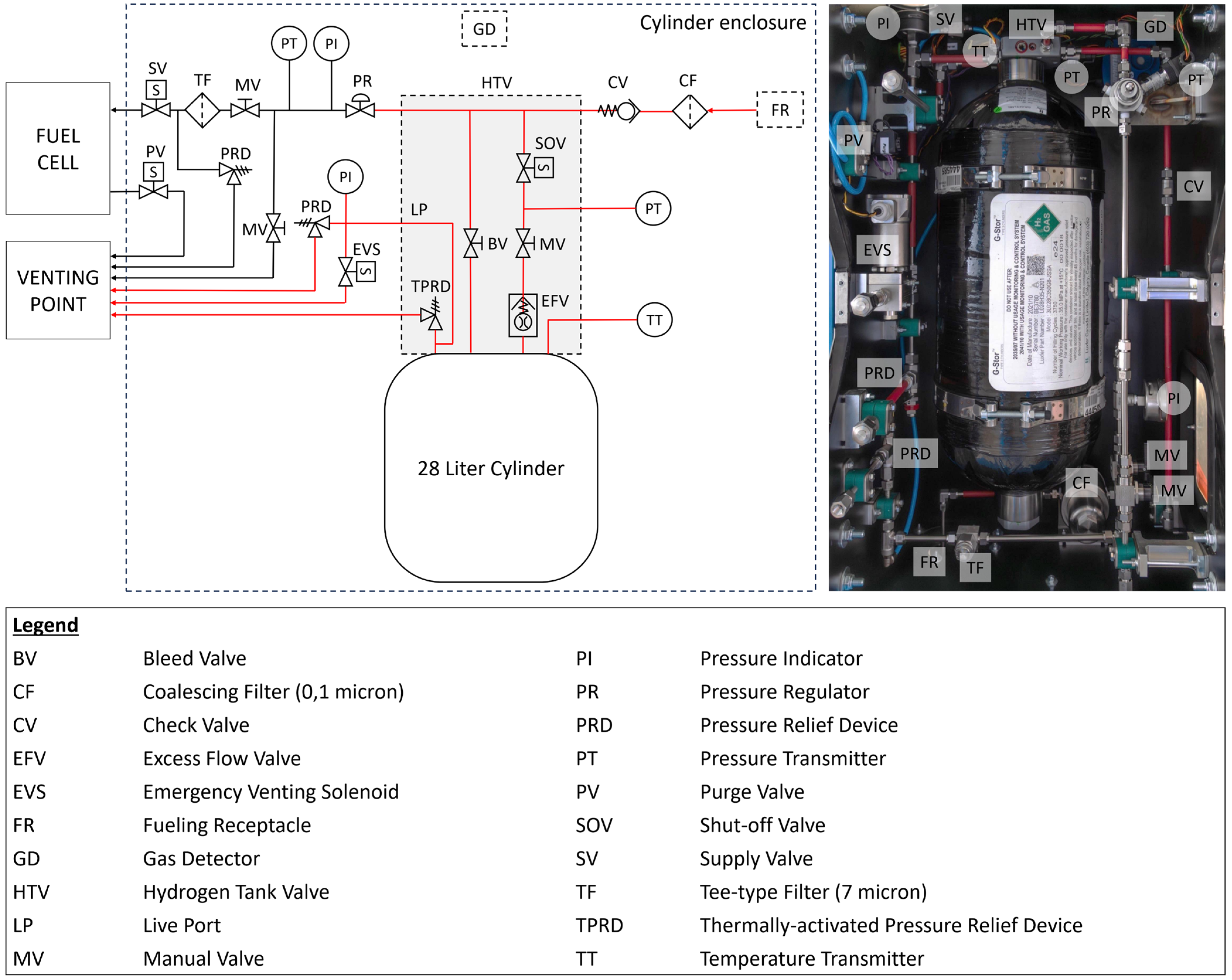
3.2. Hydrogen Storage, Fuel Delivery, and Fuel Cell Subsystems
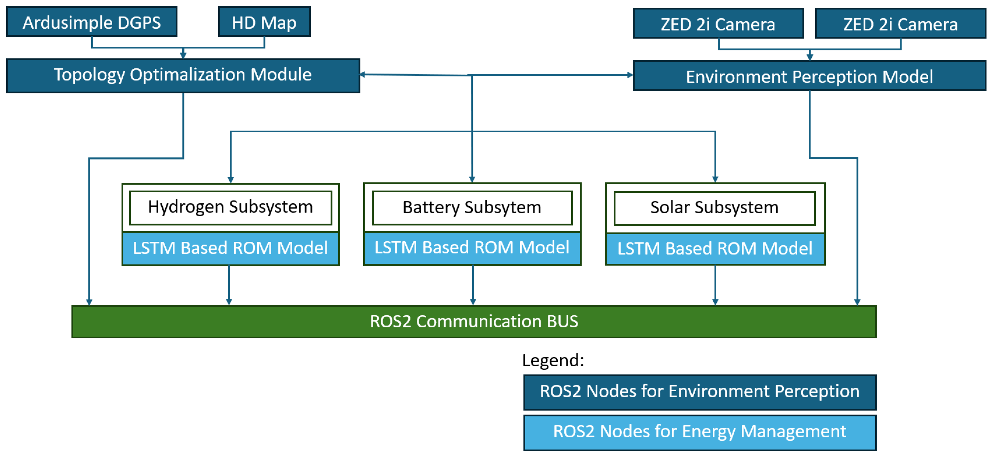
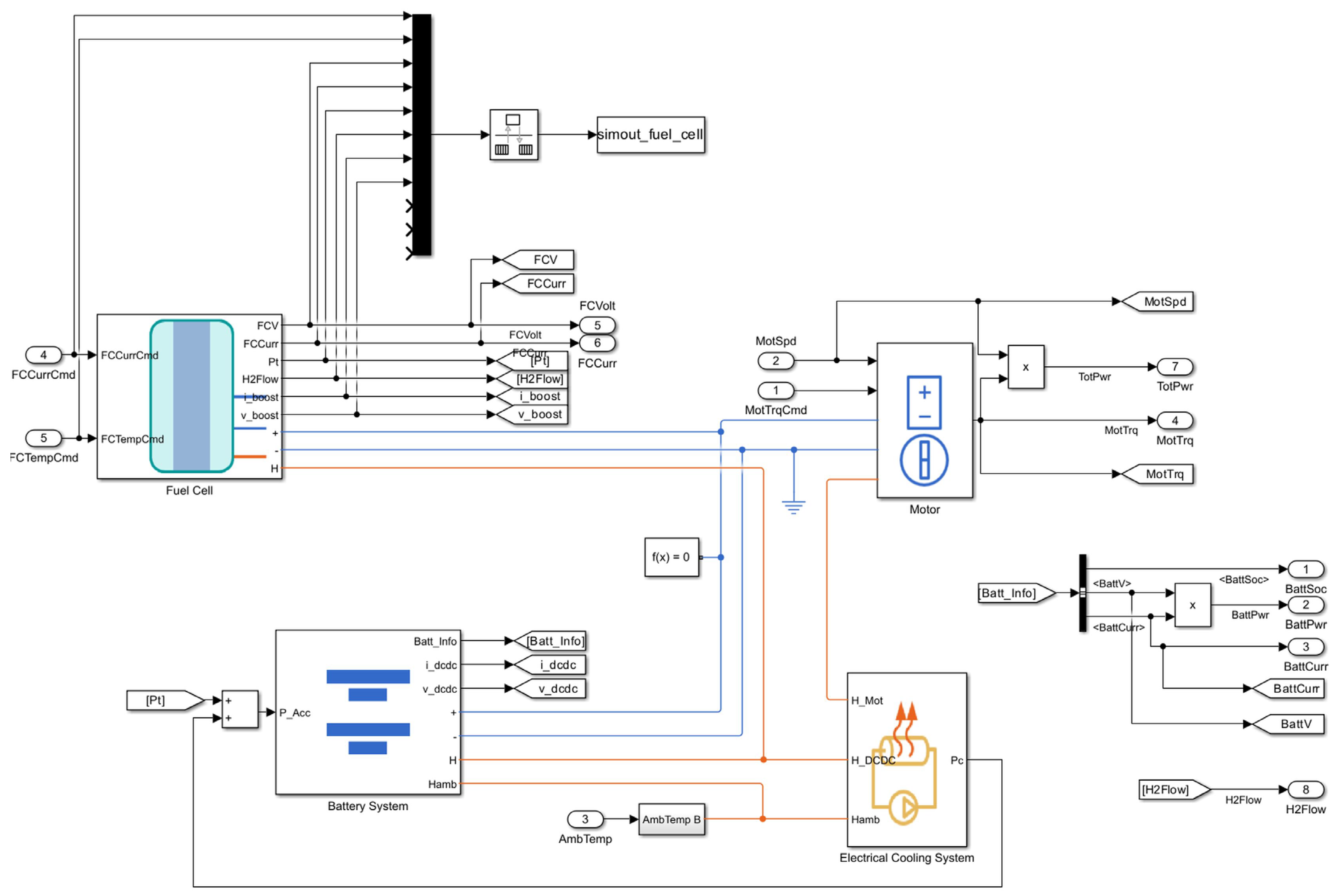
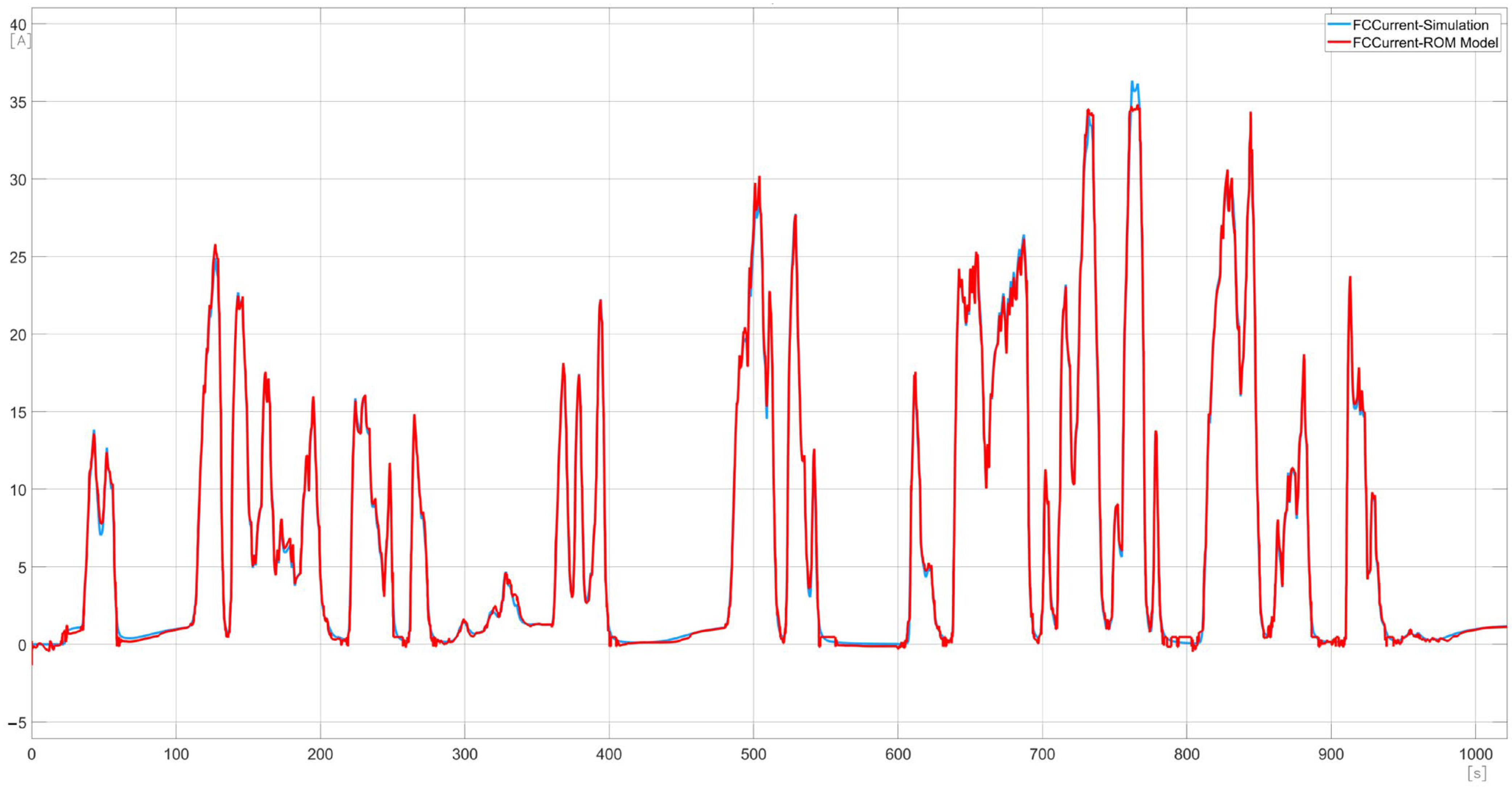
3.3. Artificial Intelligence-Driven Energy Management System
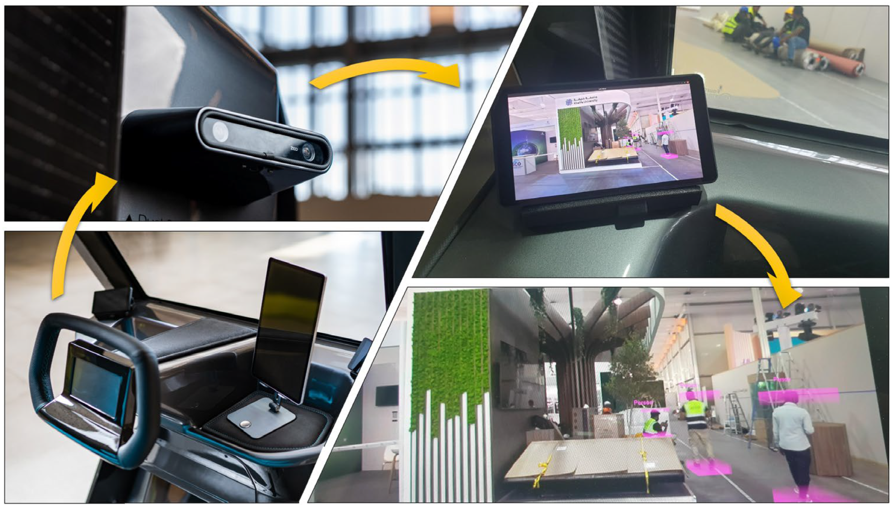
3.4. Deep Learning for Environment Recognition
- The viewer must be full screen.
- The viewer must start on system boot-up.
- In case of any issue with the USB connection, the program tries to restart itself.
- Both displays must be in lain orientation with the corresponding viewer windows.
4. Conclusions
Author Contributions
Funding
Data Availability Statement
Acknowledgments
Conflicts of Interest
References
- U.S. Energy Information Administration (EIA). Monthly Energy Review May 2023; EIA: Washington, DC, USA, 2023. [Google Scholar]
- Davis, S.C.; Diegel, S.W.; Boundy, R.G. Transportation Energy Data Book, 31st ed.; Oak Ridge National Laboratory (ORNL): Oak Ridge, TN, USA, 2012. [Google Scholar]
- IEA. CO2 Emissions from Fuel Combustion; IEA: Paris, France, 2013. [Google Scholar] [CrossRef]
- Zefreh, M.M.; Torok, A. Theoretical Comparison of the Effects of Different Traffic Conditions on Urban Road Environmental External Costs. Sustainability 2021, 13, 3541. [Google Scholar] [CrossRef]
- Kondor, I.P.; Zöldy, M.; Mihály, D. Experimental Investigation on the Performance and Emission Characteristics of a Compression Ignition Engine Using Waste-Based Tire Pyrolysis Fuel and Diesel Fuel Blends. Energies 2021, 14, 7903. [Google Scholar] [CrossRef]
- Zöldy, M.; Kondor, I.P. Simulation and Injector Bench Test Validation of Different Nozzle Hole Effect on Pyrolysis Oil-Diesel Oil Mixtures. Energies 2021, 14, 2396. [Google Scholar] [CrossRef]
- Murgia, F. P-Block Elements as Negative Electrode Materials for Magnesium-Ion Batteries: Electrochemical Mechanism and Performance. Ph.D. Thesis, Université Montpellier, Montpellier, France, 2016. [Google Scholar]
- Shafiee, S.; Topal, E. When Will Fossil Fuel Reserves Be Diminished? Energy Policy 2009, 37, 181–189. [Google Scholar] [CrossRef]
- Laimon, M.; Yusaf, T. Towards Energy Freedom: Exploring Sustainable Solutions for Energy Independence and Self-Sufficiency Using Integrated Renewable Energy-Driven Hydrogen System. Renew. Energy 2024, 222, 119948. [Google Scholar] [CrossRef]
- Baharudin, L.; Watson, M. Hydrogen Applications and Research Activities in Its Production Routes through Catalytic Hydrocarbon Conversion. Rev. Chem. Eng. 2017, 34, 43–72. [Google Scholar] [CrossRef]
- Hosseini, S.E.; Butler, B. An Overview of Development and Challenges in Hydrogen Powered Vehicles. Int. J. Green Energy 2019, 17, 13–37. [Google Scholar] [CrossRef]
- Suleman, F.; Dincer, I.; Agelin-Chaab, M. Environmental Impact Assessment and Comparison of Some Hydrogen Production Options. Int. J. Hydrogen Energy 2015, 40, 6976–6987. [Google Scholar] [CrossRef]
- IEA. Global Hydrogen Review 2023; IEA: Paris, France, 2023. [Google Scholar]
- Dincer, I.; Acar, C. Review and Evaluation of Hydrogen Production Methods for Better Sustainability. Int. J. Hydrogen Energy 2015, 40, 11094–11111. [Google Scholar] [CrossRef]
- IEA. The Future of Hydrogen: Seizing Today’s Opportunities; OECD: Paris, France, 2019. [Google Scholar] [CrossRef]
- Kis, D.I.; Kókai, E. A Review on the Factors of Liner Collapse in Type IV Hydrogen Storage Vessels. Int. J. Hydrogen Energy 2023, 50, 236–253. [Google Scholar] [CrossRef]
- Gómez, J.A.; Santos, D.M.F. The Status of On-Board Hydrogen Storage in Fuel Cell Electric Vehicles. Designs 2023, 7, 97. [Google Scholar] [CrossRef]
- Castillo Campo, O.; Alvarez Fernandez, R.; Domingo, R. Opportunities and Barriers of Hydrogen–Electric Hybrid Powertrain Vans: A Systematic Literature Review. Processes 2020, 8, 1261. [Google Scholar] [CrossRef]
- Gis, W. Ecological and Functional Aspects of Operation of Electric Vehicles With Fuel Cell. J. KONBiN 2020, 50, 165–176. [Google Scholar] [CrossRef]
- Pielecha, I.; Cieslik, W.; Andrzej, S. The Use of Electric Drive in Urban Driving Conditions Using a Hydrogen Powered Vehicle-Toyota Mirai. Combust. Engines 2018, 172, 51–58. [Google Scholar] [CrossRef]
- Vodovozov, V.; Raud, Z.; Petlenkov, E. Review of Energy Challenges and Horizons of Hydrogen City Buses. Energies 2022, 15, 6945. [Google Scholar] [CrossRef]
- Alves, M.P.; Gul, W.; Cimini Junior, C.A.; Ha, S.K. A Review on Industrial Perspectives and Challenges on Material, Manufacturing, Design and Development of Compressed Hydrogen Storage Tanks for the Transportation Sector. Energies 2022, 15, 5152. [Google Scholar] [CrossRef]
- Binder, M. Clean Urban Transport for Europe Project Final Report; EU Commission: Brussels, Belgium, 2006. [Google Scholar]
- Stolzenburg, K.; Whitehouse, N.; Whitehouse, S. JIVE D3.24/JIVE 2 D3.7 Best Practice Report; EU Commission: Brussels, Belgium, 2020. [Google Scholar]
- IEA. Global EV Outlook 2023; IEA: Paris, France, 2023. [Google Scholar]
- Li, H.; Guo, H.; Yousefi, N. A Hybrid Fuel Cell/Battery Vehicle by Considering Economy Considerations Optimized by Converged Barnacles Mating Optimizer (CBMO) Algorithm. Energy Rep. 2020, 6, 2441–2449. [Google Scholar] [CrossRef]
- Yu, P.; Li, M.; Wang, Y.; Chen, Z. Fuel Cell Hybrid Electric Vehicles: A Review of Topologies and Energy Management Strategies. World Electr. Veh. J. 2022, 13, 172. [Google Scholar] [CrossRef]
- Ragab, A.; Marei, M.I.; Mokhtar, M. Comprehensive Study of Fuel Cell Hybrid Electric Vehicles: Classification, Topologies, and Control System Comparisons. Appl. Sci. 2023, 13, 13057. [Google Scholar] [CrossRef]
- Ferrara, A.; Okoli, M.; Jakubek, S.; Hametner, C. Energy Management of Heavy-Duty Fuel Cell Electric Vehicles: Model Predictive Control for Fuel Consumption and Lifetime Optimization. IFAC-PapersOnLine 2020, 53, 14205–14210. [Google Scholar] [CrossRef]
- Wang, W.; Hao, Z.; Qu, F.; Li, W.; Wu, L.; Li, X.; Wang, P.; Ma, Y. Review of Energy Management Methods for Fuel Cell Vehicles: From the Perspective of Driving Cycle Information. Sensors 2023, 23, 8571. [Google Scholar] [CrossRef]
- Romero, O.; Miura, A.S.; Parra, L.; Lloret, J. Low-Cost System for Automatic Recognition of Driving Pattern in Assessing Interurban Mobility Using Geo-Information. ISPRS Int. J. Geoinf. 2022, 11, 597. [Google Scholar] [CrossRef]
- Babalola, P.O.; Atiba, O.E. Solar Powered Cars—A Review. IOP Conf. Ser. Mater. Sci. Eng. 2021, 1107, 012058. [Google Scholar] [CrossRef]
- Koyuncu, T. Practical Efficiency of Photovoltaic Panel Used for Solar Vehicles. In IOP Conference Series: Earth and Environmental Science; Institute of Physics Publishing: Bristol, UK, 2017; Volume 83. [Google Scholar]
- Yilanci, A.; Dincer, I.; Ozturk, H. A Review on Solar-Hydrogen/Fuel Cell Hybrid Energy Systems for Stationary Applications. Prog. Energy Combust. Sci. 2009, 35, 231–244. [Google Scholar] [CrossRef]
- DeLuchi, M.A.; Ogden, J.M. Solar-Hydrogen Fuel-Cell Vehicles. Transp. Res. Part A Policy Pract. 1993, 27, 255–275. [Google Scholar] [CrossRef]
- Felseghi, R.-A.; Așchilean, I.; Cobîrzan, N.; Bolboacă, A.M.; Raboaca, M.S. Optimal Synergy between Photovoltaic Panels and Hydrogen Fuel Cells for Green Power Supply of a Green Building—A Case Study. Sustainability 2021, 13, 6304. [Google Scholar] [CrossRef]
- Zhang, F.; Wang, B.; Gong, Z.; Zhang, X.; Qin, Z.; Jiao, K. Development of Photovoltaic-Electrolyzer-Fuel Cell System for Hydrogen Production and Power Generation. Energy 2023, 263, 125566. [Google Scholar] [CrossRef]
- Muratori, M.; Borlaug, B.; Ledna, C.; Jadun, P.; Kailas, A. Road to Zero: Research and Industry Perspectives on Zero-Emission Commercial Vehicles. iScience 2023, 26, 106751. [Google Scholar] [CrossRef]
- UNECE. Agreement Concerning the Adoption of Harmonized Technical United Nations Regulations for Wheeled Vehicles, Equipment and Parts Which Can Be Fitted and/or Be Used on Wheeled Vehicles and the Conditions for Reciprocal Recognition of Approvals Granted on the Basis of These United Nations Regulations. 2022. Available online: https://treaties.un.org/Pages/ViewDetails.aspx?src=IND&mtdsg_no=XI-B-16&chapter=11&clang=_en (accessed on 4 February 2024).
- European Parliament, Council of the European Union. Regulation (EU) No 168/2013 of the European Parliament and of the Council of 15 January 2013 on the Approval and Market Surveillance of Two- or Three-Wheel Vehicles and Quadricycles Text with EEA Relevance 2020. Available online: https://eur-lex.europa.eu/legal-content/EN/ALL/?uri=celex%3A32013R0168 (accessed on 4 February 2024).
- Regulation No. 100: Uniform Provisions Concerning the Approval of Vehicles with Regard to Specific Requirements for the Electric Power Train. 2022. Available online: https://eur-lex.europa.eu/legal-content/EN/TXT/?uri=CELEX%3A42011X0302%2801%29 (accessed on 4 February 2024).
- ISO 13063; Electrically Propelled Mopeds and Motorcycles. International Organization for Standardization: Geneva, Switzerland, 2012.
- European Commission Commission Directive 92/62/EEC of 2 July 1992 Adapting to Technical Progress Council Directive 70/311/EEC Relating to Steering Equipment for Motor Vehicles and Their Trailers. 1992. Available online: https://eur-lex.europa.eu/legal-content/EN/TXT/?uri=celex:31992L0062 (accessed on 4 February 2024).
- European Commission Commission Directive 91/662/EEC of 6 December 1991 Adapting to Technical Progress Council Directive 74/297/EEC in Respect of the Behaviour of the Steering Wheel and Column in an Impact 1991. Available online: https://eur-lex.europa.eu/legal-content/EN/ALL/?uri=celex:31991L0662 (accessed on 4 February 2024).
- UN/ECE/TRANS/Regulation No. 79-01; Uniform Provisions Concerning the Approval of: Vehicles with Regard to Steering Equipment. 1988. Available online: https://www.interregs.com/catalogue/details/ece-79/regulation-no-79-01/steering-equipment/ (accessed on 4 February 2024).
- National Highway Traffic Safety Administration. Failure Modes and Effects Analysis for Hydrogen Fuel Cell Vehicles—Subtask 1; NHTSA: Washington, DC, USA, 2009. [Google Scholar]
- Flamberg, S.; Rose, S.; Stephens, D. Analysis of Published Hydrogen Vehicle Safety Research; United States National Highway Traffic Safety Administration: Washington, DC, USA, 2010. [Google Scholar]
- Astbury, G.; Hawksworth, S. Spontaneous Ignition of Hydrogen Leaks: A Review of Postulated Mechanisms. Int. J. Hydrogen Energy 2007, 32, 2178–2185. [Google Scholar] [CrossRef]
- Liu, M.; Zhang, S. Research on Hydrogen Fuel Cell Safety Detection Analysis Based on Leakage Quality Limit Detection Method. J. Phys. Conf. Ser. 2022, 2174, 012049. [Google Scholar] [CrossRef]
- Maeda, Y.; Takahashi, M.; Tamura, Y.; Suzuki, J.; Watanabe, S. Test of Vehicle Ignition Due to Hydrogen Gas Leakage; SAE International: Warrendale, PA, USA, 2006. [Google Scholar]
- Liu, W.; Christopher, D.M. Dispersion of Hydrogen Leaking from a Hydrogen Fuel Cell Vehicle. Int. J. Hydrogen Energy 2015, 40, 16673–16682. [Google Scholar] [CrossRef]
- Regulation No 134 of the Economic Commission for Europe of the United Nations (UN/ECE) Uniform Provisions Concerning the Approval of Motor Vehicles and Their Components with Regard to the Safety-Related Performance of Hydrogen-Fuelled Vehicles (HFCV) 2019. Available online: https://op.europa.eu/en/publication-detail/-/publication/8aad3d19-7870-11e9-9f05-01aa75ed71a1/language-en (accessed on 4 February 2024).
- Snoussi, J.; Ben Elghali, S.; Benbouzid, M.; Mimouni, M. Auto-Adaptive Filtering-Based Energy Management Strategy for Fuel Cell Hybrid Electric Vehicles. Energies 2018, 11, 2118. [Google Scholar] [CrossRef]
- Liu, Y.; Liang, J.; Song, J.; Ye, J. Research on Energy Management Strategy of Fuel Cell Vehicle Based on Multi-Dimensional Dynamic Programming. Energies 2022, 15, 5190. [Google Scholar] [CrossRef]
- Tornai, K.; Oláh, A.; Drenyovszki, R.; Kovács, L.; Pinté, I.; Levendovszky, J. Recurrent Neural Network Based User Classification for Smart Grids. In Proceedings of the 2017 IEEE Power & Energy Society Innovative Smart Grid Technologies Conference (ISGT), Washington, DC, USA, 23–26 April 2017; pp. 1–5. [Google Scholar]
- Johanyak, Z.C.; Tikk, D.; Kovacs, S.; Wong, K.W. Fuzzy Rule Interpolation Matlab Toolbox—FRI Toolbox. In Proceedings of the 2006 IEEE International Conference on Fuzzy Systems, Vancouver, BC, Canada, 16–21 July 2006; pp. 351–357. [Google Scholar]
- Tornai, K.; Kovács, L.; Oláh, A.; Drenyovszki, R.; Pintér, I.; Tisza, D.; Levendovszky, J. Classification for Consumption Data in Smart Grid Based on Forecasting Time Series. Electr. Power Syst. Res. 2016, 141, 191–201. [Google Scholar] [CrossRef]
- European Parliament, Council of the European Union. Regulation No 13 of the Economic Commission for Europe of the United Nations (UN/ECE)—Uniform Provisions Concerning the Approval of Vehicles of Categories M, N and O with Regard to Braking [2016/194]. 2015. Available online: https://op.europa.eu/en/publication-detail/-/publication/0a43f880-d612-11e5-a4b5-01aa75ed71a1/language-en (accessed on 4 February 2024).
- GB/T 24549-2020; Fuel Cell Electric Vehicles—Safety Requirements. Standardization Administration of China: Beijing, China, 2020.
- SAE J2600_201510; Compressed Hydrogen Surface Vehicle Fueling Connection Devices. SAE International: Warrendale, PA, USA, 2015.
- Regulation (EC) No 79/2009 of the European Parliament and of the Council of 14 January 2009 on Type-Approval of Hydrogen-Powered Motor Vehicles, and Amending Directive 2007/46/EC 2009. Available online: https://eur-lex.europa.eu/legal-content/EN/TXT/HTML/?uri=CELEX%3A32009R0079 (accessed on 4 February 2024).
- European Commission. Atex Guidelines, 4th ed.; European Commission: Brussels, Belgium, 2012. [Google Scholar]
- Wiebe, W.; Unwerth, T.V.; Schmitz, S. Hydrogen Pump for Hydrogen Recirculation in Fuel Cell Vehicles. E3S Web Conf. 2020, 155, 01001. [Google Scholar] [CrossRef]
- Shi, L.; Tang, X.; Xu, S.; Zheng, M. Comprehensive Analysis of Shutdown Purge Influencing Factors of Proton Exchange Membrane Fuel Cell Based on Water Heat Transfer and Water Vapor Phase Change Mechanism. Appl. Therm. Eng. 2024, 239, 122175. [Google Scholar] [CrossRef]
- FCEV Reference Application. Available online: https://www.mathworks.com/help/autoblks/ug/fuel-cell-electric-vehicle-reference-application.html (accessed on 4 February 2024).
- Dataset. Available online: https://www.a2d2.audi/a2d2/en/dataset.html (accessed on 4 February 2024).


| # | Hyperparameters | Setup |
|---|---|---|
| 1 | Number of Epoch | 1 × 10⁵ |
| 2 | Gradient Threshold | 1 |
| 3 | Initial Learning Rate | 5 × 10⁻³ |
| 4 | Learning Rate Schedule | Piecewise |
| 5 | Learning Rate Drop Period | 1 × 10⁴ |
| 6 | Learning Rate Drop Factor | 0.6 |
| # | Name | Type | Activations | Learnable | States |
|---|---|---|---|---|---|
| 1 | sequenceinput Sequence input with 5 dims. | Sequence Input | 5(C) × 1(B) × 1(T) | - | - |
| 2 | fc_1 800 fully connected layers | Fully connected | 800(C) × 1(B) × 1(T) | Weights 800 × 5 Bias 800 × 1 | - |
| 3 | relu_1 ReLU | ReLU | 800(C) × 1(B) × 1(T) | - | - |
| 4 | 1stm_1 LSTM with 800 hidden units | LSTM | 800(C) × 1(B) × 1(T) | Input Weight 3200 × 800 Recurrent 3200 × 800 Bias 3200 × 1 | Hidden State Cell State |
| 5 | 1 stm_2 LSTM with 800 hidden units | LSTM | 800(C) × 1(B) × 1(T) | Input Weight 3200 × 800 Recurrent 3200 × 800 Bias 3200 × 1 | Hidden State Cell State |
| 6 | relu_1 ReLU | ReLU | 800(C) × 1(B) × 1(T) | - | - |
| 7 | fc_2 8 fully connected layers | Fully Connected | 8(C) × 1 (B) × 1(T) | Weight 8 × 800 Bias 8 × 1 | - |
| 8 | regression output means-squared-error | Regression Output | 8(C) × 1 (B) × 1(T) | - | - |
| Input Signal of ROM Model | Output Signal of ROM Model | ROM Model Accuracy Predicting |
|---|---|---|
| Motor Torque Command | Battery State of Charge [%] | 88% |
| Motor Speed [RPM] | Battery Power [W] | 96% |
| Ambient Temperature [K] | Battery Current [A] | 92% |
| Fuel Cell Temperature Command | Motor Torque [Nm] | 98% |
| Fuel Cell Current Command | Fuel Cell Voltage [V] | 94% |
| Fuel Cell Current [A] | 94% | |
| Total Power [W] | 91% | |
| H2 Flow [kg/s] | 70% |
Disclaimer/Publisher’s Note: The statements, opinions and data contained in all publications are solely those of the individual author(s) and contributor(s) and not of MDPI and/or the editor(s). MDPI and/or the editor(s) disclaim responsibility for any injury to people or property resulting from any ideas, methods, instructions or products referred to in the content. |
© 2024 by the authors. Licensee MDPI, Basel, Switzerland. This article is an open access article distributed under the terms and conditions of the Creative Commons Attribution (CC BY) license (https://creativecommons.org/licenses/by/4.0/).
Share and Cite
Kun, K.; Szabó, L.; Varga, E.; Kis, D.I. Development of a Hydrogen Fuel Cell Prototype Vehicle Supported by Artificial Intelligence for Green Urban Transport. Energies 2024, 17, 1519. https://doi.org/10.3390/en17071519
Kun K, Szabó L, Varga E, Kis DI. Development of a Hydrogen Fuel Cell Prototype Vehicle Supported by Artificial Intelligence for Green Urban Transport. Energies. 2024; 17(7):1519. https://doi.org/10.3390/en17071519
Chicago/Turabian StyleKun, Krisztián, Lóránt Szabó, Erika Varga, and Dávid István Kis. 2024. "Development of a Hydrogen Fuel Cell Prototype Vehicle Supported by Artificial Intelligence for Green Urban Transport" Energies 17, no. 7: 1519. https://doi.org/10.3390/en17071519
APA StyleKun, K., Szabó, L., Varga, E., & Kis, D. I. (2024). Development of a Hydrogen Fuel Cell Prototype Vehicle Supported by Artificial Intelligence for Green Urban Transport. Energies, 17(7), 1519. https://doi.org/10.3390/en17071519