Review

Current Progress and Development Trend of Gas Injection to Enhance Gas Recovery in Gas Reservoirs

1
Research Institute of Petroleum Exploration & Development, Beijing 100083, China
2
School of Engineering Science, University of Chinese Academy of Sciences, Beijing 101408, China
3
Institute of Porous Flow & Fiuld Mechanics, Chinese Academy of Sciences, Langfang 065007, China
*
Author to whom correspondence should be addressed.
Energies 2024, 17(7), 1595; https://doi.org/10.3390/en17071595
Submission received: 30 January 2024 / Revised: 1 March 2024 / Accepted: 8 March 2024 / Published: 26 March 2024

Abstract

:
Conventional recovery enhancement techniques are aimed at reducing the abandonment pressure, but there is an upper limit for recovery enhancement due to the energy limitation of reservoirs. Gas injection for energy supplementation has become an effective way to enhance gas recovery by reducing hydrocarbon saturation in gas reservoirs. This review systematically investigates progress in gas injection for enhanced gas recovery in three aspects: experiments, numerical simulations and field examples. It summarizes and analyzes the current research results on gas injection for EGR and explores further prospects for future research. The research results show the following: (1) Based on the differences in the physical properties of CO2, N2 and natural gas, effective cushion gas can be formed in bottom reservoirs after gas injection to achieve the effects of pressurization, energy replenishment and gravity differentiation water resistance. However, further experimental evaluation is needed for the degree of increase in penetration ability. (2) It is more beneficial to inject N2 before CO2 or the mixture of N2 and CO2 in terms of EGR effect and cost. (3) According to numerical simulation studies, water drive and condensate gas reservoirs exhibit significant recovery effects, while CO2-EGR in depleted gas reservoirs is more advantageous for burial and storage; current numerical simulations only focus on mobility mass and saturation changes and lack a mixed-phase percolation model, which leads to insufficient analysis of injection strategies and a lack of distinction among different gas extraction effects. Therefore, a mixed-phase-driven percolation model that can characterize the fluid flow path is worth studying in depth. (4) The De Wijk and Budafa Szinfelleti projects have shown that gas injection into water drive and depleted reservoirs has a large advantage for EGR, as it can enhance recovery by more than 10%. More experiments, simulation studies and demonstration projects are needed to promote the development of gas injection technology for enhanced recovery in the future.

1. Introduction

The improvement in global productivity is accompanied by the increase in energy demand year by year, so natural gas, as a clean, efficient, low-carbon fossil energy resource, has attracted much attention. As the “ballast stone” of energy security and the “stabilizer” of the traditional-to-new-energy transition, natural gas has become increasingly prominent [1]. With the increasing demand for reducing the greenhouse gas effect and fossil fuel combustion, the market demand for natural gas is gradually rising, promoting the continuous upgrading of gas field development around the world and gradually entering the stage of enhanced gas recovery [2,3,4,5]. However, traditional EGR technology is based on depletion development, reducing gas reservoir abandonment pressure [6]. Due to reservoir energy constraints, there is an upper limit to the enhancement in recovery. To solve this problem, gas injection has become a promising method [7,8,9] which is mainly based on external gas injection to replenish reservoir energy, pressurize and displace residual gas and reduce residual gas saturation.
The key goal of conventional EGR technology is to maximize depletion and achieve more efficient utilization of underground natural gas resources by improving the reserve utilization degree, the pressure drop in the conformance coefficient and the pressure depletion efficiency. In order to achieve this goal, various technical methods have been proposed, including well pattern encryption [10], well pattern optimization [11], reservoir reconstruction [12] and drainage gas recovery [13,14]. However, these technologies still have limitations; so, the gas injection method has been developed. By injecting CO2, N2 and their mixtures, recovery efficiency in gas reservoirs can be effectively enhanced, and the long-term stable production of gas fields can be supported [15]. Specifically, CO2 injection can not only help to enhance gas recovery but also allow for the capture and storage of CO2 to deal with the current greenhouse effect. Field tests have shown that CO2 storage in depleted gas reservoirs is effective and can enhance gas recovery [15,16,17,18,19,20,21,22]. At the same time, N2 plays an outstanding role in enhanced gas recovery [8,23], due to its abundant resources, sufficient gas source and low cost. In addition, the mixture of CO2 and N2 combines the advantages of the two, reducing pore expansion, enhancing gas recovery and allowing for CO2 storage [24,25,26].
By reviewing the existing experimental and numerical simulation studies, as well as field research examples, this paper summarizes the research status of the injection of CO2, N2 and their mixtures to enhance gas recovery and points out research prospects. Firstly, the second section compares the physical properties of CO2, N2 and natural gas and discusses the mechanism of their injection for EGR. Section 3 reviews core displacement experiments with CO2, N2 and their mixtures. Section 4 describes numerical studies on enhanced gas recovery that used gas injection on a gas reservoir scale, including EGR effects on different gas reservoirs, injection strategies, and evaluation and analysis of reservoir physical properties and injection parameters. Section 5 focuses on specific research examples of gas injection-based EGR; finally, it summarizes the conclusion and explores research prospects.

2. Gas Injection to Enhance Gas Recovery

2.1. Properties of Gas Injection Medium

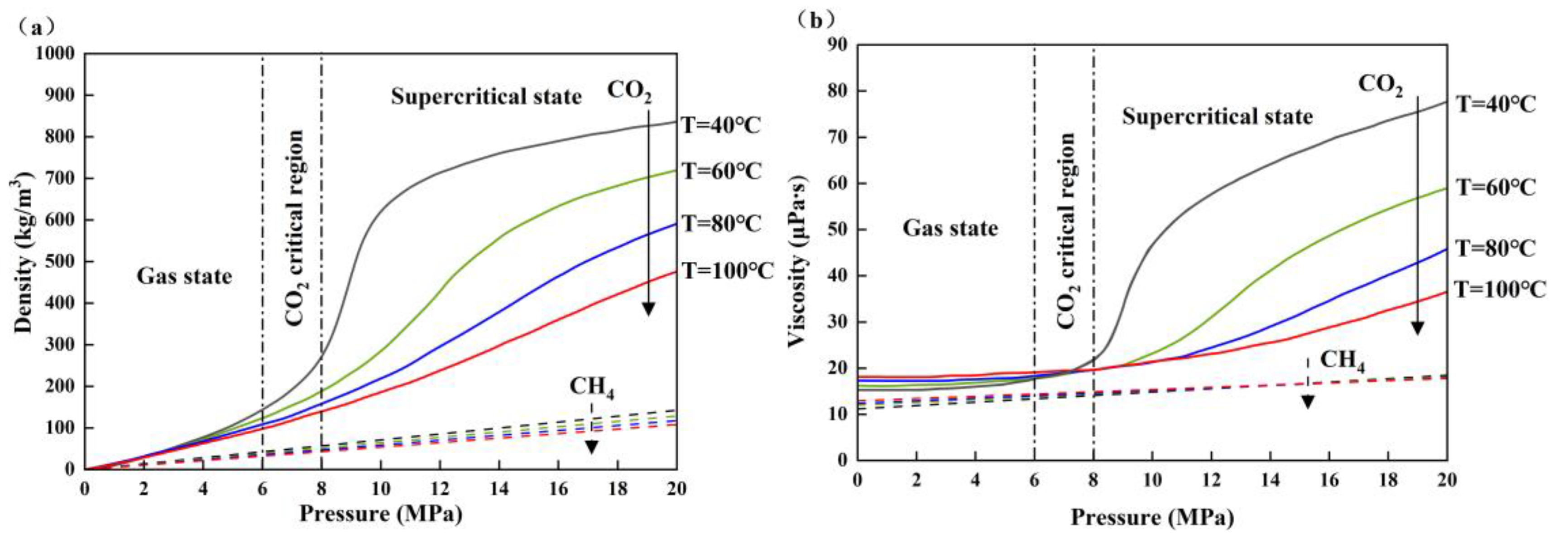
2.1.1. Physical Properties of CO2 and Natural Gas

As a special acid gas, CO2 does not only dissolve in water but also reacts with it to produce carbonic acid after injection into the formation, which improves permeability and CO2 capture. In addition, with the change in temperature and pressure, CO2 exists in different states, i.e., solid, gas, liquid and supercritical states, as shown in Figure 1. At standard temperature and pressure, CO2 is a thermodynamically stable gas with a density of about 1.98 kg/m3, which is 1.67 times that of air. When the pressure is higher than 7.38 MPa and the temperature is higher than 31.1 °C, CO2 exists in a special state (supercritical state), whereby it resembles a gas but has the density of a liquid [27].
In the supercritical state, the density of CO2 is close to that of a liquid and almost two orders of magnitude larger than that of natural gas, as shown in Figure 2a. The density difference between CO2 and CH4 leads to gravitational differentiation: denser CO2 tends to sink to the bottom of the reservoir, forming a “cushion gas” beneath less dense natural gas, which facilitates gas production [28,29]. In addition, under reservoir conditions, CO2 is about an order of magnitude more viscous than CH4, favoring the CO2 displacement of CH4 [30], as shown in Figure 2b. In a general reservoir, the temperature and pressure conditions can meet the requirements for CO2 to reach the supercritical state.

2.1.2. Physical Properties of N2 and Natural Gas

N2, being an inert gas with stable properties and abundant resources, is typically obtained through air separation. The temperature and pressure of N2 under formation conditions exhibit significant variations compared with standard temperature and pressure conditions. Table 1 provides critical parameters for N2 and CH4 [32].
At different temperatures, the density and viscosity of N2 and CH4 both increase significantly with the increase in pressure, but the density of N2 is always higher than that of CH4, and the density difference between the two remains basically unchanged, as shown in Figure 3a. Similar to the density, the viscosity of N2 and CH4 also increases with the increase in pressure, as shown in Figure 3b. At the same temperature, the viscosity difference between N2 and CH4 expands with the increase in pressure. However, under a certain pressure, the viscosity difference decreases slightly with the increase in temperature. In general, the viscosity difference does not change significantly with the increase in temperature but shows an obvious tendency to increase with the increase in pressure [33].

2.2. Gas Injection Mechanism

2.2.1. Mechanism of CO2 Injection to Enhance Gas Recovery

With more and more attention being paid to environmental problems such as the greenhouse effect, the technology of using CO2 as a driving gas to enhance gas recovery and storage by injection into gas reservoirs has developed rapidly. The in-depth study of the mechanism of CO2-enhanced gas recovery is conducive to better implementation of enhanced gas recovery technology. The main mechanism is as follows:
  • Cushion gas: When the temperature is greater than 31.04 °C and the pressure is greater than 7.38 MPa, CO2 reaches a supercritical state, with the viscosity of a gas and the density of a liquid, which is easier to achieve in the gas reservoir. The continuous injection of CO2 enhances the thickness of the underlying CO2 cushion and effectively isolates the aquifer. Simultaneously, the miscible displacement of CO2 and natural gas promotes the upward displacement of residual natural gas in the reservoir, thereby enhancing gas reservoir recovery [34,35], as illustrated in Figure 4.
    Figure 4. Schematic diagram of CO2 cushion mechanism [36].
    Figure 4. Schematic diagram of CO2 cushion mechanism [36].
    Energies 17 01595 g004
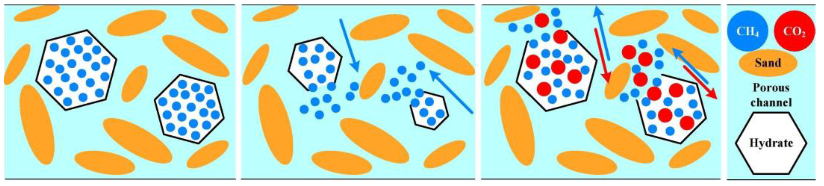
  • Competitive adsorption displacement: CO2 has a stronger adsorption capacity than CH4 on the reservoir rock surface, and there is an advantage of competitive adsorption (the shale and coal seam phenomena are more significant) [37]. Therefore, CO2 can displace CH4 adsorbed on the rock surface and transform it into a free state, as shown in Figure 5. Under low temperature and high pressure, CH4 molecules combine with water molecules to form a crystal structure, constituting methane hydrate. Therefore, the stability of methane hydrate is affected by factors such as temperature, pressure and water content. Due to the stronger adsorption capacity of CO2 and its reaction with water, it is easier to promote the decomposition of methane hydrate formed by water locking, replace the CH4 molecules therein and extract them, so as to enhance gas recovery [38], as shown in Figure 6.
    Figure 5. Competitive adsorption of CO2 and CH4 [39].
    Figure 5. Competitive adsorption of CO2 and CH4 [39].
    Energies 17 01595 g005
  • Energy replenishment and penetration ability increase: CO2 injection into the reservoir can effectively supplement the gas reservoir energy, increase the reservoir pressure and even restore the remaining gas to the initial pressure, prolong the service life and further enhance gas recovery. In addition, the higher the abandonment pressure of the formation, the stronger the ability of the reservoir to adsorb CO2, and the higher the recovery; further, the replenishment of the reservoir energy will strengthen the adsorption and substitution mechanism [34]. At the same time, CO2 can extract reservoir rock surface water, clean water and gas flow channel in the condensate gas block area; change hydrophilic wettability; reduce gas seepage resistance; and facilitate more residual gas recovery [40].

2.2.2. Mechanism of N2 Injection to Enhance Gas Recovery

As an inert gas, N2 has good stability and sufficient air source (air separation and compression) and is non-corrosive and non-toxic. N2 as a driving gas to enhance gas reservoir recovery also has significant advantages. The main mechanism is as follows:
  • Gravity differentiation water resistance: For the edge- and bottom-water gas reservoirs, the continuous injection of N2 can effectively form gravity differentiation slug, reduce the water invasion velocity, reduce water production and reduce the water–gas ratio of the gas well [41]. At the same time, N2 and natural gas can form complete miscible displacement and reduce the residual gas saturation of the water lock.
  • Energy replenishment and penetration ability increase: N2, as the driving gas, is continuously injected, and the supplement formation energy effect is obvious. For depleted gas reservoirs, N2 injection can supplement formation energy (Nitrogen-Assisted Depletion Drive (NADD)), delay pressure reduction and maintain stable production of gas wells. In water-flooded gas reservoirs, N2 injection supplements formation energy (Nitrogen-Enhanced Residual Gas (NERG)), reduces water invasion velocity, reduces water production and improves the gas productivity of gas wells [23], as shown in Figure 7. Both of the above cases can effectively enhance gas recovery. In addition, the N2 compression coefficient is smaller than that of CO2, and the injection amount to replenish the same energy is smaller. Similarly, N2 can effectively reduce the expansion of rock clay and increase the permeability of the reservoir [42].

2.2.3. Mechanism of CO2 and N2 Mixture Injection to Enhance Gas Recovery

The main components of the mixture are CO2 and N2. Under the joint action of the two gas displacement mechanisms, while CO2 dissolves in water to delay gas breakthrough, N2 maintains displacement energy. Figure 8 shows the action mechanism of the mixture to enhance gas recovery. The mixture not only has the EGR mechanism advantages of the two gases but also has two additional outstanding advantages. The presence of CO2 makes the mixtures have a competitive adsorption advantage. Due to the high viscosity between CO2 and the pore surface, the injected gas can easily self-adsorb and strengthen CH4 desorption, which is conducive to storage and production [43]. The injection of CO2 causes matrix expansion and adversely affects formation permeability, which damages the gas production and injection capacity of CO2. On the contrary, N2 injection leads to formation shrinkage and increases gas injection capacity and production [44].
In summary, although there are some differences in the mechanism of different gases, the overall effect of different gases on gas reservoirs to EGR is very significant. Table 2 organizes the mechanisms of different types of gases to EGR.

3. Laboratory Experiment of Gas–Gas Displacement

In the process of gas displacement, due to the effect of convection and diffusion, a gas mixing zone is produced to form miscible displacement, which causes premature mixing and premature breakthrough and adversely affects recovery. In order to further explore the characteristics of gas mixing and natural gas recovery and analyze the feasibility and mechanism of gas injection to enhance recovery, researchers have carried out a large number of experimental studies. This section systematically introduces in detail the published experimental studies on the feasibility, mechanism and gas mixing characteristics of gas injection for EGR.

3.1. CO2–Natural Gas Displacement Experiment

At present, many studies have been performed on the feasibility and mechanism of enhanced gas recovery by using CO2 as the driving gas, Table 3 records the current status of experimental studies on CO2 injection for EGR. In 2002, Mamora et al. [45] used carbonate cores for the supercritical CO2 displacement of CH4. The results showed that the injection of supercritical CO2 could enhance the displacement efficiency and re-pressurize the reservoir, effectively displacing CH4, and the recovery of CH4 was between 73% and 87%. In 2017, Shi Yunqing et al. [46,47] used the high-temperature and high-pressure long-core displacement system produced by ST Company of France to conduct a long-core displacement experiment. The gas production at the outlet was recorded in real time, the gas composition at the outlet was analyzed, and the breakthrough characteristics of CO2 migration were monitored. The results showed that the ultimate recovery efficiency was increased by 17.3% on the basis of depleted production. In 2022, Ding Jingchen et al. [48] used the natural core of a DS gas field of a tight sandstone gas reservoir in western China to carry out a long-core experiment of supercritical CO2 injection after core gas depletion. The experiment shows that injection of supercritical CO2 after gas depletion could increase gas recovery by 18.9%. At the same time, the mechanism analysis shows that under the condition of low permeability, high water saturation and large inclination angle, the supercritical CO2 injection had a good effect. In 2019, Wang et al. [40] focused on studying the interface properties of all the fluids involved in the CO2 injection gas reservoir, such as contact angle, wettability and minimum miscible pressure (MMP), and found that the condensate gas and CO2 could be completely miscible at relatively low pressure, which was conducive to CO2 eliminating the condensate gas blockage near the well. By extracting water, CO2 reduces the hydrophilic wettability of rocks, which is conducive to relieving the resistance of water to gas flow. It can be seen that it is feasible to enhance gas reservoir recovery by CO2 injection, which is conducive to lifting the water lock and increasing permeability.
Formation water affects the degree of CO2 gas displacement and mixing to a great extent [49,50], and the dispersion coefficient is the standard to measure the degree of mixing [51,52]. In 2016, Honari et al.’s [53] study showed that bound water occupied part of the flow channel and dissolved part of CO2, effectively reducing the adverse influence of core heterogeneity on sweep efficiency. As a result, CH4 recovery was enhanced. Zecca et al. [54] observed a significant increase in dispersion with water saturation in the core and established an empirical function accordingly. Abba et al. [55,56] extended their study to include the effects of primary water salinity. The results show that the dispersion coefficient decreases with the increase in salinity. In this sense, the primary water salinity affects the mixing of CO2 and residual natural gas in the reservoir.
Table 3. Experimental status of enhanced gas recovery by CO2 injection.
Research FocusResearch Gas TypeExperimental ConditionsObservations and Conclusion
Technical feasibility of EGRMamora et al. (2002) [45]CO2Carbonate core: 2.54 cm × 30.5 cm; k: 50 mD, ϕ: 23%; T: 20–60 °C; P: 3.45–20.67 MPa.The injection of supercritical CO2 could improve displacement efficiency and re-pressurize the reservoir, effectively displacing CH4, and the recovery of CH4 was between 73% and 87%.
Shi et al. (2017) [46,47]CO2Natural outcrop sandstone: 1 m × 2.5 cm; k: 0.652 mD, ϕ: 9.9%; T: 85 °C; P: 25 MPa.With the increase in the injection ratio of supercritical CO2, the ultimate recovery rate increased by 17.3% on the basis of depleted production.
Ding et al. (2022) [48]CO2Tight sandstone core: 80 cm long; k: 0.11 mD, ϕ: 6.98%; T: 82 °C; P: 27 MPa.Injection of supercritical CO2 after gas reservoir depletion could increase gas recovery by 18.9%.
Fluid interface properties, such as contact angle, wettability, MMP, etc.Wang et al. (2019) [40]CO2Sample of tight sandstone.CO2 can eliminate the clogging of condensate gas near the well and reduces the hydrophilic wettability of rock by pumping water, which is conducive to relieving the resistance of water to gas flow.
Influence of residual waterHonari et al. (2016) [50]CO2Sandstone core, carbonate core: 3.75–3.80 cm × 10.04–10.47 cm; k: 460, 12, 2912, ϕ: 20%, 16%, 23%; T: 40 °C; P: 10 MPa.Bound water occupied part of the flow channel and dissolved part of CO2, effectively reducing the adverse influence of core heterogeneity on sweep efficiency.
Zecca et al. (2017) [54]CO2Sandstone core: 3.75–3.76 cm × 10.04–10.10 cm; k: 460, 12 mD, 20%, 15%; T: 36 °C; P: 10 MPa.Dispersion was observed to increase significantly with water saturation in the core.
Salinity effectsAbba et al. (2018 b) [55,56]CO2Berea sandstone core: 2.522 cm × 7.627 cm; k: 217 mD, ϕ: 20.3%; T: 40 °C; P: 8.963 MPa.The dispersion coefficient decreases with the increase in salinity; primary water salinity affects the mixing of CO2 and residual natural gas in the reservoir.
Φ = porosity

3.2. N2–Natural Gas Displacement Experiment

N2 is often used as a driving gas because of its sufficient gas source and stable physical properties. Table 4 documents the current status of experiments on EGR by N2 injection. In 2020, Mohammed et al. [57] believed that the disadvantages of the excessive mixing of CO2 and the high compression ratio hindered the economic benefit of the whole process, so N2 was used to conduct displacement experiments in order to determine the optimal injection rate. The results show that the injection rate with a medium Peclet number made the displacement process have a low mixing effect and was more favorable to displacement. The gas injection method for EGR proposed by Mohammed and Abbas et al. [58] in 2021 involves injecting an appropriate amount of N2 before CO2 injection. In comparison to conventional CO2 injection, this novel approach demonstrated a 10.64% increase in CH4 recovery and a 24.84% enhancement in CO2 storage. It can be seen that this method can extend the production time of clean natural gas and maximize the production of natural gas, but the effect of primary water on this method needs further study.

3.3. Mixture–Natural Gas Displacement Experiment

Much experimental research has also been conducted using CO2 and N2 mixtures as the driving gas, and the current status of the mixtures for EGR experiments is documented in Table 5. In 2008, TurTA et al. [59] carried out physical simulation experiments on enhanced gas recovery from reservoir rock samples by displacement with pure CO2, N2 and their mixtures in different proportions in the laboratory; the results showed that recovery from rock samples could reach 73–87% when CO2 broke through, their mixtures’ displacement effect was better than that of pure CO2 or N2 displacement and recovery with pure CO2 or N2 gas displacement was basically the same. Due to the high solubility of CO2 in water, the delayed breakthrough in the process of mixed gas displacement can not only ensure the recovery but also reduce the impact of CO2 on the corrosion of production wells. Omari et al. [42] also showed the dual advantages of gas mixtures: the presence of CO2 can compete to adsorb and displace CH4; the presence of N2 can offset the adverse effect of CO2 expansion on formation permeability.
In 2008, Sim and Brunelle et al. [60] carried out displacement experiments using two gas mixtures: the first one comprised 90% CO2, 5% N2 and 5% SO2 to simulate combustion flue gas; the second comprised 60% SO2 and 40% CO2 to simulate the acid gas produced by the acid gas device. Their research shows that chemical reactions within porous media appeared to result in an increased mixing of displacement and replacement gases. This suggests that gas reservoirs with high water saturation or aquifers are more suitable for flue gas or acid gas injection sequestration while displacing residual gas production. In 2009, Sim et al. [61] studied gas displacement efficiency in gas reservoirs and further confirmed that during mixed gas displacement, the breakthrough time of CO2 was significantly delayed compared with N2 due to its high solubility in bound water, which is conducive to enhancing the recovery of CH4 and reducing the cost of corrosion treatment. At the same time, it is conducive to the storage of greenhouse gas CO2 in the gas reservoir.
This section summarizes laboratory experiments on CO2, N2 and mixtures. In the oil and gas industry, CO2 has good properties and can both enhance gas recovery and be stored to cope with the greenhouse effect. Therefore, the experimental studies mainly focus on CO2 as the driving gas; however, injecting an appropriate amount of N2 before CO2 injection or CO2 and N2 mixtures is more beneficial in terms of EGR effect and cost, because the breakthrough time is extended, and the presence of N2 ensures efficient displacement and replacement. It is also worth noting that the presence of formation water has a profound effect on the degree of mixing between recovery enhancement and gas–gas displacement.

4. Numerical Simulation of Enhanced Gas Recovery by Gas Injection

Numerical simulation is an effective method to study and evaluate the process of gas injection EGR. By employing numerical simulation methods, researchers have successfully validated the technical and economic viability of gas injection for EGR [34,41,62,63,64,65]. Consequently, this study aims to investigate and analyze the EGR impact, injection strategy, reservoir physical properties and injection parameters across diverse gas reservoirs.

4.1. Effects of Gas Injection on Different Gas Reservoirs

There are many types of gas reservoirs, which can be divided into different gas reservoirs according to different factors. The methods of gas injection to enhance gas recovery have different effects on different kinds of gas reservoirs. According to the investigation, the gas reservoirs studied and analyzed by numerical simulation can be divided into water drive gas reservoirs, condensate gas reservoirs and depleted gas reservoirs. The effect degree of gas injection for the three types of gas reservoirs will be introduced below.

4.1.1. Water Drive Gas Reservoirs

Due to the relatively low sweep efficiency and the trapped gas in the water invasion zone, the recovery rate of water drive gas reservoirs is between 35 and 75% [66,67]. The ultimate recovery factor is usually due to physical properties such as residual gas saturation controlled by the water edge, while the water invasion rate is directly related to pressure changes, capillary action and rock wettability. In the early stages of production, water drive gas reservoirs maintain reservoir pressure and productivity for a short period of time but later make production challenging. Gas–water contact increases; water cone production is extended; many large gas masses are bypassed and left behind the erosion front, increasing residual gas saturation in the reservoir, severely affecting recovery; and formation water treatment costs are high [68]. In addition, the tight combination of gas and water in gas wells can lead to the formation of gas hydrates in the pipelines.
The effect of the gas injection method on the recovery efficiency of water drive gas reservoirs is very significant. Table 6 records numerical simulation studies on water drive gas reservoirs. In 2017, Zangeneh and Safarzadeh et al. [69] focused on a water drive condensate gas reservoir in southern Iran and proposed a CO2 injection scheme to enhance gas reservoir recovery. Three cases were compared and analyzed: no aquifer impact, aquifer impact and initial CO2 injection. The results showed that the aquifer impact would lead to a 21% reduction in cumulative gas production; CO2 injection in a water drive gas reservoir can enhance gas recovery by 27% and condensate recovery by 58%, with significant effects. This is because CO2 injection can effectively drive natural gas to the production well, forming a CO2 plume above the aquifer, inhibiting aquifer invasion and maintaining reservoir pressure. It is proved that CO2 injection for water drive gas reservoirs can disperse to form plumes, block water invasion, maintain pressure, replenish energy and enhance gas recovery. However, because CO2 injection is chosen in the initial stage of production, the cost is not considered.
In EGR in water drive gas reservoirs, the relationship between injection position and gas–water contact is very important. In 2014, Ogolo et al. [35] selected a strong water drive condensate gas reservoir for numerical simulation and analysis of CO2 injection in reservoirs. The simulation results show that CO2 injection at the gas–water contact induced a very significant improvement in gas reservoir recovery compared with water drive production, with the recovery rate of natural gas being increased by more than 10% and the recovery rate of condensate being increased by about 4%. In addition, the effect of controlling water invasion was also very obvious, and the amount of water invasion was reduced by 60%. Due to the physical characteristics of fluids, CO2 forms an interval layer, and water invasion only affects the CO2 layer, while the upper layer of natural gas is not affected. It can be seen that when CO2 is injected at the beginning of production, it forms an isolation zone, making the water drive gas reservoir become a depleted gas reservoir or a partially depleted gas reservoir. Khan et al. [64] had the injection well located below the aquifer and injected CO2 for reservoir simulation. The results show that because CO2 was injected below the aquifer, it could effectively delay CO2 breakthrough and enhance gas reservoir recovery by vertical completion and dissolution in the aquifer. Adler [41] used a numerical simulation method to simulate N2 injection in water drive gas reservoirs and natural water gas reservoirs and found that there was little difference in recovery efficiency above or below the gas–water contact, indicating that injection wells are not really sensitive to small changes in the original gas–water interface during gas production, but injection in deep water may cause N2 to be trapped and lose effectiveness.
In summary, gas injection in water drive gas reservoirs can significantly enhance recovery because the injected gas can be pressurized to control water and reduce water invasion. Different injection locations have different effects on the whole EGR process of gas reservoirs, but the overall improvement in gas recovery is beneficial. In the future, different injection locations need to be analyzed and the mechanisms evaluated.

4.1.2. Condensate Gas Reservoirs

Condensate gas reservoirs are special gas reservoirs between reservoirs and gas reservoirs which can produce both gas and condensate gas. They have high economic value, but there are many difficulties in production. Under continuous production, the reservoir pressure drops below the dew point pressure, resulting in condensation of the heavier components in the reservoir. Gas reservoir production lowers the average reservoir pressure below the dew point, and the pressure in the near-wellbore area also drops below the dew point [70]. This causes condensate to be released and remain on the pore surface of the reservoir and near the well, clogging the pore space and reducing the relative permeability of the gas [71,72], which can reduce the productivity of the gas to as low as 80% [73].
The gas injection method can significantly enhance gas recovery and gas recovery of condensate in gas reservoirs. Table 7 records numerical simulation studies on condensate gas reservoirs. CO2 is selected as the driving gas, CO2 is injected into the formation, the reservoir is pressurized, the condensate evaporates again, and permeability is increased. At the same time, CO2 dissolves in the condensate oil, changes the physical properties of the condensate gas, greatly reduces the viscosity of the condensate gas, reduces the capillary force and flow resistance in the migration process and increases the energy of dissolved gas drive; further, the condensate gas and residual gas move correspondingly under the displacement of CO2.
In 2014, Narinesingh and Alexander [74] used CMG-GME to construct a model of depletion in condensate gas reservoirs in Trinidad and Tobago. It was directly observed that CO2 injection could increase reservoir pressure and decrease condensate saturation, indicating that the condensate re-evaporates and moves. Leeuwenburgh et al. [75] analyzed a condensate field in the Netherlands that was already in the EGR stage. The simulation results showed that due to depletion production, the gas production increased by 0.6%, and the condensate production increased by 0.56%. The results indicate that the economic benefits should be taken into account when gas injection is used in EGR in a well-depleted gas field due to small residual reserves.
Different gas injection methods have different effects on EGR in condensate gas reservoirs with different permeability capacity. El Morsy et al. [76] constructed an ideal reservoir model, focusing on tight condensate gas reservoirs, and set 0.1 mD and 1 mD permeability reservoirs for continuous gas injection, and huff and puff gas injection, respectively, for comparison. The analysis concluded that CO2 huff and puff gas injection is better for tight condensate gas reservoirs and continuous gas injection is better for condensate gas reservoirs with better permeability.

4.1.3. Depleted Gas Reservoirs

A depleted gas reservoir may have a residual gas saturation of more than 15% [78]. If no measures are taken to extend its service life, the platform is stopped or dismantled, the gas well is abandoned, and the pipeline remains idle accordingly, which causes certain economic losses. Table 8 records numerical simulation studies on depleted gas reservoir. For depleted gas reservoirs, CO2 is selected as the driving gas, which can not only displace residual gas to enhance gas recovery but also store CO2.
In 2018, Attique Amer et al. [79] studied a newly discovered gas reservoir in western Poland with a shallow reservoir and good permeability. Reservoir simulation software was used to simulate and analyze the entire production process of the gas reservoir. Gas injection production could achieve an additional recovery rate of 14% and could store 60 million tons of CO2, which was more economical. In 2014, Leeuwenburgh et al. [75] conducted a numerical reservoir simulation study on a depleted dry gas field in the Netherlands, and the results showed that gas injection could increase the recovery of natural gas in the dry gas field by 1%. This shows that in abandoned gas reservoirs, due to good depletion production, the enhanced recovery rate is low, but it is economical to extend the production time and sequester CO2. Raza et al. [80] focused on studying the storage performance of CO2 sequestered in abandoned gas reservoirs by using numerical simulation software, and the results showed that abandoned gas reservoirs have great potential for CO2 sequestering. On the whole, gas injection in depleted gas reservoirs may have little advantage in terms of recovery efficiency, but these reservoirs are good sites for CO2 storage.
In addition, many scholars have also combined CO2-EGR with geothermal energy extraction, providing development ideas for this technology. The process uses supercritical CO2 instead of traditional water or salt water as an underground heat transfer working fluid to develop geothermal energy while ultimately storing all the injected CO2. In 2021, Ezekiel et al. [81] used numerical simulations to model a combined CO2-EGR-CPG system, showing that depleted high-temperature gas reservoirs can both form plumes and spread more residual gas and can be ideal sites for geothermal energy deployment.

4.2. Injection Strategy Research

Using numerical simulation as a tool, with the advantages of fast, simple and multi-scenario analysis, in the whole gas reservoir numerical simulation and simulation process, the corresponding injection strategy can be designed according to different research purposes, and different cases can be analyzed and compared. This provides a clearer understanding of the entire gas injection EGR process and helps to adjust and optimize injection strategies to achieve greater recovery. At present, researchers are conducting numerical simulation studies on different injection strategies for different purposes, as shown in Table 9.
Aiming at addressing the problems of water invasion and low recovery efficiency in water drive gas reservoirs, gas injection is used to control water and produce gas. Zangeneh and Safarzadeh [69] designed three cases: ignoring the impact of aquifer on the gas reservoir, conventional depletion water drive production and CO2 injection production simulation at the start of production. A comparison of case 1 and case 2, highlighting the impact of active aquifers on production, showed that the aquifer impact reduced cumulative gas production by 21%. The case 2 vs. 3 comparison investigated the effects of CO2 injection on reducing aquifer erosion and hydrocarbon production. Ogolo et al. [35] also designed two cases for the analysis of EGR with gas injection control, depletion water drive production for 30 years and primary production accompanied by CO2 injection for 30 years, to analyze the effect of reducing water invasion and enhancing gas recovery.
For EGR in depleted gas reservoirs, Attique Amer et al.’s [79] scenario design comprised start of production in 2015, 17 years of depletion production, 2 months of shut-in, 4 years and 10 months of gas injection and production, and 30 years of gas injection and storage. The analysis shows that after the depletion of the gas reservoir, recovery after gas injection could be increased by 14%, the effect was significant, the production life could be extended, and economic value could be obtained. Raza et al. [80] conducted a numerical simulation study focusing on CO2 sequestration. The case simulation was as follows: 20 years of depleted production, 20 years of shut-in, 10 years of CO2 injection, followed by 70 years of observation. Based on the case simulation observation, the evaluation of residual gas at storage sites and the capture mechanism were analyzed.
In 2013, Gou et al. [82], in the numerical simulation and analysis of the Altmark gas field in Germany, focused on the influence of the original reservoir flow field and adopted a basic model, where one well injected CO2 and one well produced natural gas. A case comparison analysis with model changes, i.e., only CO2 injection without gas production and only gas production without injection, showed that regardless of gas production inclusion, the mass fraction distribution of injected CO2 in the reservoir was similar, because it was controlled by the original flow field. Ezekiel et al. [81] focused on the combined CO2-EGR-CPG system, considering the extraction of geothermal energy while enhancing gas recovery. Therefore, after studying the depletion of gas reservoirs, they conducted a comparative analysis on whether there was a depleted gas reservoir degree and the formation stage of CO2 plume after studying the depletion of gas reservoirs. The results showed that under the condition of incomplete depletion, high flow injection and low flow production formed a plume, and the gas recovery rate was the best. The best effect of geothermal energy extraction was thus achieved.

4.3. Research on the Influence of Reservoir Physical Properties and Injection Parameters

Reservoir physical properties and injection parameters play a key role in driving the underground displacement of gas and natural gas and significantly affect the ultimate enhanced natural gas recovery when gas injection is used to enhance gas recovery. Table 10 shows influence studies on reservoir heterogeneity, dip angle, permeability distribution and perforation location, gas injection pressure, timing and rate, injection gas type and injection well selection.
Oldenburg et al. [83] proposed that permeability heterogeneity is conducive to the formation of fast flow channels and tends to accelerate CO2 breakthrough. Rebscher and Oldenburg [84] and Gou et al. [82] also revealed that CO2 preferentially breaks through in highly permeable geological layers in heterogeneous reservoirs. Moreover, in reservoirs containing faults, CO2 migration is affected by faults, leading to rapid breakthrough. This is detrimental to enhanced gas recovery. Al-hasami et al. [85], Kalra and Wu [86] proposed that water injected in highly permeable layers, or formation water, can delay CO2 breakthrough by effectively blocking fast flow paths and CO2 dissolution. Feather and Archer [87] confirmed that low-permeability, isotropic and homogeneous reservoirs are good targets for CO2-EGR applications.
Table 10. Main numerical simulation studies on reservoir properties and operating parameters of gas injection for enhanced gas recovery.
Research ObjectiveResearchSimulatorModel Size
(km)
Depth
(m)
Permeability and Porosity
(mD; %)
Injection Rate
(m3/day)
Effect of permeability heterogeneityOldenburg et al. (2001) [28], Rebscher and Oldenburg (2005) [84]TOUCH26.6 × 1 × 0.1/kx: 1000, kz: 10; 353.58 × 10⁵
Gou et al. (2013) [82]TOUGH2MP-FLAC3D4.4 × 2 × 1340011; 21/
Feather and Archer (2010) [87]ECLIPSE1.524 × 1.524 × 0.03 /kx: 100, kz: 1–10; 201616.16–32,424.24
Effect of injected water vs. formation waterKalra et al. (2014) [86]CMG-GME2.286 × 0.02286 × 0.09153048100; 201616.16
Effect of inclinationAdler et al. (1983) [41]///1, 50, 250, 500; 5, 10, 2085,170,255 × 103
Penetration layer distribution in relation to perforation locationKalra et al. (2014) [86]CMG-GME2.286 × 0.02286 × 0.091530481, 5, 10, 50, 100; 201.27 × 10⁵
Injection pressureNarinesingh and Alexander (2014) [74]CMG-GME2.43 × 0.045 × 0.0453992.88 90–180; 22–281.42 × 10⁵
Injection gas typeLeeuwenburgh et al. (2014) [75]////A gas field: (0.3–3.2) × 105; Gas field B: (0.2–15) × 105
Morsy et al. (2020) [76]///0.1, 1; 20/
Injection gas timingClemens (2002) [88]/4 × 2 × 0.06/104–55; /(6.07–8.28) × 105
Jukic et al. (2021) [77]//2410/; 2–18/
Jikich et al. (2003) [89]UTCOMP804.67 × 804.67 × 3.96/5.5; 114040.4–335,353.4
Hashami et al. (2005) [85]/1.2192 × 1.2192 × 0.0372133.6 40; 204.25 × 10⁵
Hussen et al. (2012) [90]tempest1.7 × 2.3 × 0.33650kx: 6–390, ky 6–390, kz: 4–370; 4–172.42 × 10⁶
Injection rateSeo and Mamora et al. (2005) [91]/0.20119 × 0.20119 × 0.04572; 0.2845 × 0.2845 × 0.09144/kx: 50, kz: 10; 35202.02, 404.04
Adler et al. [41] first studied the influence of the dip angle of gas injection EGR on recovery by setting a gradually increasing dip gradient in simulation, revealing that the greater the dip angle, the better the effect of gas injection EGR. Further, the greater the dip angle, the more easily dispersed the aquifer invasion, and the better the effect of gas gravity displacement. Kalra et al. [86] also obtained similar results. At the same time, they also proposed the relationship between permeability distribution and perforation location, and the impact on enhanced gas recovery. The analysis concluded that injection wells perforation in reservoirs with low permeability can expand the swept area, production wells’ perforation location in low-permeability reservoirs can delay the CO2 breakthrough time, and intermediate reservoirs have good permeability and can leave enough permeability space to maximize the displacement and replacement of natural gas.
Narinesingh and Alexander [74] focused on the effect of injection pressure on gas and condensate recovery in condensate reservoirs. Different injection pressure tests showed that increasing injection pressure can effectively improve gas and condensate recovery, but a too-high injection pressure can increase the liquid loading effect in the wellbore and reduce the production time. For the injection gas types, the numerical simulation analysis mainly used CO2, N2 and their mixtures. Leeuwenburgh et al. [75] conducted numerical simulation analysis on a condensate gas field in the Netherlands using CO2 and N2 to simulate enhanced gas recovery, and the results showed that the recovery rates obtained by the two gases were almost the same. This shows that in conventional gas reservoirs, gas injection is mainly used to drive and sweep natural gas, and there are also errors that do not take into account mixing and solubility. El Morsy et al. [76] studied the effect of mixed gas on enhanced gas recovery and revealed that the effect of mixture gas injection in tight condensate gas reservoirs was not much different from that of pure CO2, which would be more economical but would have an impact on condensate gas production, because N2 would reduce the minimum miscible pressure of CO2.
Gas injection timing is a crucial parameter in EGR. Clemens et al. [88], Liu et al. [31] and Jukic et al. [77] conducted multi-scenario comparative simulation of reservoirs to analyze the gas recovery efficiency of CO2 injection in different stages of gas field development. It was found that the maximum gas recovery rate could be obtained by injecting CO2 when the gas reservoir was depleted. Premature injection of CO2 in the early stages of gas field development has been shown to be detrimental to enhanced recovery. Jikich et al. [89] and Hashami et al. [85] simulated a sandstone reservoir in northern West Virginia and compared different scenarios to show that the recovery rate was the best after gas injection after gas reservoir depletion, when primary production reaches the economic limit. Similar results were obtained in the two studies. Hussen et al. [90] conducted reservoir simulation analysis for known gas reservoirs and found that the maximum recovery was achieved by CO2 injection when the bottom-hole pressure was below the lower limit.
Overall, injection timing is an important factor in enhancing gas recovery in gas reservoirs. The adjustment of injection timing is mainly controlled according to the degree of gas reservoir depletion, production economic benefit and bottom-hole pressure. The regulation standard of injection timing needs to be further perfected in the future.
In addition to injection timing, the gas injection rate is another key operating parameter in EGR and is related to the injection pressure. The higher the injection pressure, the higher the injection rate, so its overall effect on the recovery factor is similar to that of injection pressure. Seo and Mamora [91] showed that the recovery increases with the injection rate within a certain range. Feather and Archer [87] reached a similar conclusion, i.e., high injection rates are advantageous for gas recovery in the later stages of field development. Kalra et al. [86] also focused on the injection rate and concluded that the recovery rate would not change much if the injection pressure was not greater than the initial reservoir pressure. However, with the increase in injection rate, the volume of CO2 injected into the reservoir would decrease, because at higher injection rates, the reservoir pressure would quickly reach the maximum pressure. Thus, less time is allowed for CO2 injection. Therefore, for the injection rate, future research should consider many aspects in the comprehensive analysis of the best injection rate.
Moreover, Leeuwenburgh et al. [75] proposed a porosity replacement injection method, whereby the injection rate is equal to the natural gas production rate of the nearby production wells. Studies have shown that the porosity replacement method can slightly increase natural gas production and promote a slow increase in the driving gas fraction. At the same time, they also focused on the selection of injection wells and proposed that the evaluation criteria for the selection of injection wells be based on the target pipeline pressure value, minimum and maximum gas rates, minimum bottom-hole pressure and maximum water–gas ratio. The results show that in terms of EGR, there is an appropriate distance between injection well and production well, which is conducive to slow gas breakthrough.

5. Examples of Gas Injection EGR Research

Research on gas injection to enhance gas recovery is not only limited to experiments and numerical simulations but also includes case studies on specific gas fields. While gas injection EGR technology in condensate gas reservoirs is basically mature, gas injection for EGR in dry gas reservoirs is still in the exploration stage in the later stage of development. Therefore, this section mainly introduces research examples of dry gas reservoirs, as shown in Table 11.
The Medvedevich gas field is a giant gas field in Russia belonging to elastic water drive gas reservoirs, with a gas bearing area of 3126.6 km2, recoverable reserves of 1.548 × 10¹² m3, a buried depth of 1100 m, an effective thickness of 33.6–54.4 m, a porosity of 27% and a permeability of 0.5–3500 mD. The original formation pressure is 11.7–11.87 MPa. The authors selected the YK-6 and YK-7 well areas (including 63 wells) for the test, N2 injection in the late stage of development to produce low-pressure free gas (no flooded area) and water sealed gas (flooded area) in the gas reservoir. After 20 years of depletion development, N2 began to be injected for 13 years of development; then, injection was stopped for 14 years. A total of 10 injection wells were used, and the gas produced was calculated from the actual output of the existing 53 production wells. The predicted results show that at the end of the 13th year after N2 injection, the total injected volume was equivalent to twice the flooded pore volume of the gas reservoir test area, about 430 million square meters; with 110 × 108 m3 gas extracted, the ultimate recovery rate of N2 injection development increased from 93.5% to 97.4%, which was 3.9% higher than that of depletion development [92].
The De Wijk gas field consists of three regions: south, north and east. The porosity and permeability of different strata are very different, and the heterogeneity is significant. The eastern reservoirs have an average thickness of 103 m, an average porosity of 14% and a permeability of 300–700 mD. The southern gas-bearing reservoir is 1.6–17 m, with an average porosity of 24% and a permeability of 1000–3000 mD. The buried depth is 1200–1300 m, and the gas–water interface is 1300 m. From 2014 to 2015, N2 injection was used to enhance gas recovery in depleted gas reservoirs and water-flooded gas reservoirs. The dry gas reservoir was injected in WYK-25, and the adjacent well, WYK-17B, was highly productive, with a well distance of 700 m; the daily gas production increased from 100,000 m3 to 160,000 m3. The water-flooded gas reservoir was injected with N2 through WYK-15B, and pressure was recorded at the WYK-26 well, which began to produce effectively one year later. During the gas production process, the pressure rose from 1 MPa to 8 MPa and remained at about 7 MPa, and the pressurization effect was obvious. The displacement effect of the two methods was very obvious in the actual production performance of the gas well and the predicted results. The estimated recovery rate increased from 73% to 83%. It is expected to increase gas production by 2.8 billion cubic meters by 2030 [23].
The Budafa Szinfelleti gas field is a weakly water-driven sandstone gas reservoir located in southwest Hungary. The geological reserves are 17 billion square meters, the original formation pressure is 33.4 MPa, and the volume concentration of CO2 is 81%. The buried depth of the gas layer is 3200–3400 m, the effective thickness is 15 m, the porosity is 21%, and the permeability is 5–40 mD. CO2 (80% CO2 and 20% CH4) was injected when the gas was recovered to 67%, the gas source was from the nearby CO2 reservoir, the well distance was 500 m, the CO2 breakthrough time was 1.5 years, and the recovery added value reached 11.6%. The amount of CO2 injected was 35% of the original hydrocarbon volume [34,47,93].
The Sawan gas field in Pakistan is a narrow and long structural gas reservoir with geological reserves of 45 billion square meters. The original formation pressure is 37.2 MPa, the temperature is 176 °C, the geothermal gradient is large, and the CO2 content is 8.39%. The sand reservoir of the third Cretaceous period is highly heterogeneous, buried at a depth of 3200 m, with a porosity of 14–24% and a permeability of 0.07–507 mD. The numerical simulation study results showed that the best development effect was achieved when the injection well was located on the side of the structure. The recovery could be increased to about 1.6%, but the output resulted in about 32% CO2 [15].
The Schoenkirchen Uebertief gas field in Austria has a diagonal anticlinal structure (15.5 × 2.2 km) with 20 billion square meters of geological reserves. The original formation pressure is 59.8 MPa, and the CO2 content is 11.72%. The buried depth is 5700 m, the effective thickness is 600 m, the porosity is 3–4%, and the permeability is 1–10 mD. It was put into production in 1969, and 1.5 million tons of CO2 was injected per year until 2010. It is predicted that after 16 years, the displacement efficiency was better. The injection well is located at the edge of the gas reservoir as far as possible, and the production well is located at the end of the structure; the recovery rate could increase by 1.5% compared with exhaustion development [15,94].

6. Conclusions

In this paper, the research progress in gas injection to enhance gas recovery is systematically reviewed in the aspects of experiments, numerical simulations and field examples. The following conclusions can be drawn from this review:
  • Based on the advantages of the physical properties of CO2 and N2, from the perspective of the mechanism, effective cushion gas can be formed after injection into the reservoir to drive up natural gas recovery, and the goal of increasing pressure and supplementing energy can be reached to the maximum extent, which is the most important result and the basis for completing other mechanism effects. For water drive gas reservoirs such as edge- and bottom-water reservoirs, the advantage of gravity differentiation water resistance after gas injection is very obvious. And because of the good adsorption ability of CO2 porous medium, it is easier to complete the competitive adsorption replacement of natural gas.
  • In laboratory experiments, CO2 is predominantly employed as the driving gas. However, it is more advantageous to precede CO2 injection with the injection of N2 or a mixture of CO2 and N2 in terms of both enhanced gas recovery effectiveness and cost efficiency. This approach prolongs breakthrough by facilitating CO2 dissolution in water, while the presence of N2 ensures not only efficient displacement but also mitigates the extent of CO2 corrosion.
  • Numerical simulations demonstrate that water drive gas reservoirs and condensate gas reservoirs exhibit significant enhanced gas recovery, while depleted gas reservoirs have limited advantages in EGR but are more suitable for CO2 storage. Reservoir heterogeneity easily promotes the formation of high-permeability channels, which can be mitigated by the presence of formation water to stabilize displacement. Due to the absence of a mixed percolation model and conventional gas reservoir simulation, differences in gas extraction efficiency are not apparent. Injection rate and timing play crucial roles in determining EGR outcomes.
  • Field case studies demonstrate that gas injection has a significant impact on enhancing gas reservoir recovery and its enforceability. Specifically, the highly representative De Wijk gas field in the Netherlands and Budafa Szinfelleti gas field in Hungary highlight the advantages of employing gas injection for water drive and depleted gas reservoirs to enhance gas recovery. Moreover, it is evident that gas injection exerts a noticeable pressurization effect, resulting in an increase in gas recovery exceeding 10%. These findings lay a solid foundation for the potential commercial application of this method.

7. Prospects

Although a lot of research has been performed on gas injection for enhanced gas recovery (EGR) in terms of experiments and simulations, current research is still in its infancy and needs to be further improved in the future. Therefore, future technology research is further recommended as follows:
  • In the mechanism of gas injection to enhance gas recovery, there are few experimental studies on the mechanism for increasing penetration ability. After different gas injection configurations, the changes in reservoir permeability and porosity are not clear enough, and the improvement degree of permeability is not specific. It is suggested to use visualization technology to measure and quantify the changes in reservoir physical properties after gas injection and to characterize and evaluate the improvement in penetration ability.
  • The mixing mechanism is mainly affected by the mixing dispersion caused by diffusion and convection. In the future, the mixing mechanism, including physical and chemical action, should be further studied to understand the seepage behavior and displacement mechanism. The investigation of dispersion in gas displacement focuses on the dispersion behavior of supercritical CO2 and N2 mixtures and on the influence of residual water and salinity on dispersion, as well as the dispersion behavior and effect under water invasion and flooding. Based on the above, the mixed dispersion model should be constructed based on experiments, and numerical simulations should be applied to provide help for specific field development.
  • In numerical simulations, the traditional Darcy seepage model can output the fluid flow and observe the saturation change, but it is not enough for the simulation of gas injection for enhanced gas recovery. It is very important to characterize the gas flow path in gas injection, which can be used to analyze the injection strategy and observe the sweep and breakthrough characteristics. Therefore, a flow path characterization model should be constructed and incorporated into reservoir simulation.
  • For deep, high-temperature gas reservoirs, it is very promising to use supercritical CO2 storage to enhance gas recovery and exploit geothermal energy at the same time, which is worthy of further study.

Author Contributions

Writing—original draft, writing—review and editing, conceptualization, B.L.; conceptualization, Y.W. and S.G.; supervision, L.Y., H.L., W.Z., J.Z. and D.H. All authors have read and agreed to the published version of the manuscript.

Funding

Scientific and technological project of PetroChina’s Oil, Gas and New Energy Branch, “Significant development test for natural gas enhanced recovery” (2023YQX105).

Conflicts of Interest

The authors declare no conflict of interest.

References

  1. Li, L. Development of natural gas industry in China: Review and prospect. Nat. Gas Ind. B 2022, 9, 187–196. [Google Scholar] [CrossRef]
  2. Wang, Z.; Fan, Z.; Zhang, X.; Liu, B.; Chen, X. Status, Trends and Enlightenment of Global Oil and Gas Development in 2021. Pet. Explor. Dev. 2022, 49, 1210–1228. [Google Scholar] [CrossRef]
  3. Hassan Shetol, M.; Moklesur Rahman, M.; Sarder, R.; Ismail Hossain, M.; Kabir Riday, F. Present Status of Bangladesh Gas Fields and Future Development: A Review. J. Nat. Gas Geosci. 2019, 4, 347–354. [Google Scholar] [CrossRef]
  4. Yong, R.; Hu, Y.; Peng, X.; Mei, Q.Y.; Qi, T.; Yang, J.; Zhang, L. Progress and prospect of enhanced gas recovery technology in the Sichuan Basin. J. Nat. Gas Ind. 2023, 43, 23–35. [Google Scholar] [CrossRef]
  5. Ma, X.; He, D.; Wei, Y.; Guo, J.; Jia, C. Enhanced gas recovery: Theory, technology and prospect. J. Nat. Gas Ind. 2023, 10, 393–405. [Google Scholar] [CrossRef]
  6. Ping, G.; Shasha, J.; Caizhen, P. Technologies and Countermeasures for Gas Recovery Enhancement. Nat. Gas Ind. B 2014, 1, 96–102. [Google Scholar] [CrossRef]
  7. Hongjun, X.; Lei, S. CO2 injection to improve recovery facter of gas reservoir. J. Nat. Gas Explor. Dev. 2006. [Google Scholar]
  8. Lin, J.; Ren, T.; Cheng, Y.; Nemcik, J.; Wang, G. Cyclic N2 Injection for Enhanced Coal Seam Gas Recovery: A Laboratory Study. Energy 2019, 188, 116115. [Google Scholar] [CrossRef]
  9. Iddphonce, R.; Wang, J.; Zhao, L. Review of CO2 Injection Techniques for Enhanced Shale Gas Recovery: Prospect and Challenges. J. Nat. Gas Sci. Eng. 2020, 77, 103240. [Google Scholar] [CrossRef]
  10. Guoting, W.; Ailin, J.; Zhi, G. Effect evaluation and adjustment countermeasures of tight gas development well patterns in the Sulige Gas Field. J. Nat. Gas Ind. 2023, 43, 66–79. [Google Scholar] [CrossRef]
  11. Yunsheng, W. A new way of evaluation productivity of staged fracturing horizontal well in tight gas reservoir. J. Nat. Gas Ind. 2012, 35, 32–34. [Google Scholar] [CrossRef]
  12. Yongqiang, F.; Ye, H. Reservoir stimulation techniques and their application to the Longwangmiao Fm gas resevoirs in the Sichuan Basin. J. Nat. Gas Ind. 2014, 34, 93–96. [Google Scholar] [CrossRef]
  13. Yong, H.; Yingli, C. The formation development and theoretical connotations of “overall water control of gas reservoir” technology in gas field development. J. Nat. Gas Ind. 2022, 42, 10–20. [Google Scholar] [CrossRef]
  14. Gao, S.; Zhang, J.; Liu, H.; Ye, L.; Zhu, W.; Xiong, W. Water-Gas Ratio Characteristics and Development Concepts for Water-Producing Gas Reservoirs. Heliyon 2023, 9, e19201. [Google Scholar] [CrossRef]
  15. Clemens, T.; Secklehner, S.; Mantatzis, K.; Jacobs, B. Enhanced Gas Recovery, Challenges Shown at the Example of Three Gas Fields. In Proceedings of the SPE EUROPEC/EAGE Annual Conference, Barcelona, Spain, 14–17 June 2010; p. SPE 130151. [Google Scholar]
  16. Vandeweijer, V.; Hofstee, C. CO2 Injection at K12-B, the Final Story. In Proceedings of the 15th International Conference on Greenhouse Gas Control Technologies, Abu Dhabi, United Arab Emirates, 5–8 October 2021; Available online: https://ssrn.com/abstract=3820865 (accessed on 29 April 2023).
  17. Vandeweijer, V.; Van Der Meer, B.; Hofstee, C.; Mulders, F.; D’Hoore, D.; Graven, H. Monitoring the CO2 Injection Site: K12-B. Energy Procedia 2011, 4, 5471–5478. [Google Scholar] [CrossRef]
  18. Audigane, P.; Oldenburg, C.; van der Meer, B.; Geel, K.; Lions, J.; Gaus, I.; Robelin, C.; Durst, P.; Xu, T. Hydrodynamics and Geochemical Modelling of CO2 Injection at the K12B Gas Field. In Proceedings of the 69th EAGE Conference and Exhibition incorporating SPE EUROPEC 2007, London, UK, 11–14 June 2007; p. cp-27-00174. [Google Scholar] [CrossRef]
  19. Kreft, E.; Brouwer, G.K.; Hofstee, C.; Wildenborg, A.F.B.; Audigane, P.; Gozalpour, F.; D‘Hoore, D.; Hartman, J.; van der Meer, L.G.H.; Geel, C.R. Results of the Second Test Program in K12-B, a Site for CO2 Storage and Enhanced Gas Recovery. In Proceedings of the 68th EAGE Conference and Exhibition incorporating SPE EUROPEC 2006, Vienna, Austria, 12–15 June 2006; p. cp-2-00288. [Google Scholar] [CrossRef]
  20. Underschultz, J.; Boreham, C.; Dance, T.; Stalker, L.; Freifeld, B.; Kirste, D.; Ennis-King, J. CO2 Storage in a Depleted Gas Field: An Overview of the CO2CRC Otway Project and Initial Results. Int. J. Greenh. Gas Control 2011, 5, 922–932. [Google Scholar] [CrossRef]
  21. Jenkins, C.R.; Cook, P.J.; Ennis-King, J.; Undershultz, J.; Boreham, C.; Dance, T.; De Caritat, P.; Etheridge, D.M.; Freifeld, B.M.; Hortle, A.; et al. Safe Storage and Effective Monitoring of CO2 in Depleted Gas Fields. Proc. Natl. Acad. Sci. USA 2012, 109, E35–E41. [Google Scholar] [CrossRef] [PubMed]
  22. Kühn, M.; Förster, A.; Großmann, J.; Lillie, J.; Pilz, P.; Reinicke, K.M.; Schäfer, D.; Tesmer, M. The Altmark Natural Gas Field Is Prepared for the Enhanced Gas Recovery Pilot Test with CO2. Energy Procedia 2013, 37, 6777–6785. [Google Scholar] [CrossRef]
  23. Goswami, R.; Seeberger, F.C.; Bosman, G. Enhanced Gas Recovery of an Ageing Field Utilizing N2 Displacement: De Wijk Field, The Netherlands. Geol. Soc. Lond. Spec. Publ. 2018, 469, 237–251. [Google Scholar] [CrossRef]
  24. Mohammed, N.; Abubakar, A.J.; Enyi, G.C.; Ghavami, G.N. Flow Characteristics Through Gas Alternating Gas Injection During Enhanced Gas Recovery. In Proceedings of the SPE Gas & Oil Technology Showcase and Conference, Dubai, United Arab Emirates, 21–23 October 2019; p. SPE-198658-MS. [Google Scholar]
  25. Fan, C.; Elsworth, D.; Li, S.; Chen, Z.; Luo, M.; Song, Y.; Zhang, H. Modelling and Optimization of Enhanced Coalbed Methane Recovery Using CO2/N2 Mixtures. Fuel 2019, 253, 1114–1129. [Google Scholar] [CrossRef]
  26. Zhang, Y.; Liu, S.; Chen, M.; Xu, S. Experimental Study on Dispersion Characteristics and CH4 Recovery Efficiency of CO2, N2 and Their Mixtures for Enhancing Gas Recovery. J. Pet. Sci. Eng. 2022, 216, 110756. [Google Scholar] [CrossRef]
  27. Ramachandran, H.; Pope, G.A.; Srinivasan, S. Effect of Thermodynamic Phase Changes on CO2 Leakage. Energy Procedia 2014, 63, 3735–3745. [Google Scholar] [CrossRef]
  28. Oldenburg, C.M.; Benson, S.M. Carbon Sequestration with Enhanced Gas Recovery: Identifying Candidate Sites for Pilot Study. Lawrence Berkeley National Laboratory: Alameda County, CA, USA, 2001; Available online: http://escholarship.org/uc/item/2qn563v5 (accessed on 29 April 2023).
  29. Liao, H.; Pan, W.; He, Y.; Fang, X.; Zhang, Y. Study on the Mechanism of CO2 Injection to Improve Tight Sandstone Gas Recovery. Energy Rep. 2023, 9, 645–656. [Google Scholar] [CrossRef]
  30. Biagi, J.; Agarwal, R.; Zhang, Z. Simulation and Optimization of Enhanced Gas Recovery Utilizing CO2. Energy 2016, 94, 78–86. [Google Scholar] [CrossRef]
  31. Liu, S.-Y.; Ren, B.; Li, H.-Y.; Yang, Y.-Z.; Wang, Z.-Q.; Wang, B.; Xu, J.-C.; Agarwal, R. CO2 Storage with Enhanced Gas Recovery (CSEGR): A Review of Experimental and Numerical Studies. Pet. Sci. 2022, 19, 594–607. [Google Scholar] [CrossRef]
  32. Shoushtari, S.; NamDar, H.; Jafari, A. Utilization of CO2 and N2 as Cushion Gas in Underground Gas Storage Process: A Review. J. Energy Storage 2023, 67, 107596. [Google Scholar] [CrossRef]
  33. Ran, W. A Numerical Simulation Study of Underground Gas Storage in Depleted Gas Reservoirs with N2 as Cushion Gas. Master’s Thesis, Southwest Petroleum University, Chengdu, China, 2020. [Google Scholar]
  34. Wang, W.; Wen, J.; Wang, C.; Gomari, S.R.; Xu, X.; Zheng, S.; Su, Y.; Li, L.; Hao, Y.; Li, D. Current Status and Development Trends of CO2 Storage with Enhanced Natural Gas Recovery (CS-EGR). Fuel 2023, 349, 128555. [Google Scholar] [CrossRef]
  35. Ogolo, N.A.; Isebor, J.O.; Onyekonwu, M.O. Feasibility Study of Improved Gas Recovery by Water Influx Control in Water Drive Gas Reservoirs. In Proceedings of the SPE Nigeria Annual International Conference, Lagos, Nigeria, 5–7 August 2014; p. SPE-172364-MS. [Google Scholar]
  36. Yang, S.; Zhimin, D. Phase behavior of CO2 sequestration and the enhanced natural gas recovery. J. Nat. Gas Ind. 2012, 32, 39–42. [Google Scholar] [CrossRef]
  37. Wolf, J.; Maaref, S.; Esmaeili, S.; Tutolo, B.; Kantzas, A. An Experimental Study on the Effects of Competitive Adsorption During Huff-N-Puff Enhanced Gas Recovery. In Proceedings of the SPE Canadian Energy Technology Conference, Calgary, AB, Canada, 15–16 March 2023. [Google Scholar] [CrossRef]
  38. Chen, Y.; Gao, Y.; Zhao, Y.; Chen, L.; Dong, C.; Sun, B. Experimental Investigation of Different Factors Influencing the Replacement Efficiency of CO2 for Methane Hydrate. Appl. Energy 2018, 228, 309–316. [Google Scholar] [CrossRef]
  39. Godec, M.; Koperna, G.; Petrusak, R.; Oudinot, A. Enhanced Gas Recovery and CO2 Storage in Gas Shales: A Summary Review of Its Status and Potential. Energy Procedia 2014, 63, 5849–5857. [Google Scholar] [CrossRef]
  40. Wang, J.; Ryan, D.; Szabries, M.; Jaeger, P. A Study for Using CO2 To Enhance Natural Gas Recovery from Tight Reservoirs. Energy Fuels 2019, 33, 3821–3827. [Google Scholar] [CrossRef]
  41. Adler, A.B. Nitrogen Injection Into Water-Driven Natural Gas or Condensate Reservoirs Increases Recovery. In Proceedings of the 58th Annual Technical Conference, San Francisco, CA, USA, 5–8 October 1983; p. SPE 12046. [Google Scholar]
  42. Omari, A.; Wang, C.; Li, Y.; Xu, X. The Progress of Enhanced Gas Recovery (EGR) in Shale Gas Reservoirs: A Review of Theory, Experiments, and Simulations. J. Pet. Sci. Eng. 2022, 213, 110461. [Google Scholar] [CrossRef]
  43. Carchini, G.; Hussein, I.; Al-Marri, M.J.; Shawabkeh, R.; Mahmoud, M.; Aparicio, S. A Theoretical Study of Gas Adsorption on α-Quartz (0 0 1) for CO2 Enhanced Natural Gas Recovery. Appl. Surf. Sci. 2020, 525, 146472. [Google Scholar] [CrossRef]
  44. Lu, Y.; Ao, X.; Tang, J.; Jia, Y.; Zhang, X.; Chen, Y. Swelling of Shale in Supercritical Carbon Dioxide. J. Nat. Gas Sci. Eng. 2016, 30, 268–275. [Google Scholar] [CrossRef]
  45. Mamora, D.D.; Seo, J.G. Enhanced Gas Recovery by Carbon Dioxide Sequestration in Depleted Gas Reservoirs. In Proceedings of the SPE Annual Technical Conference, San Antonio, TX, USA, 29 September–2 October 2002; p. SPE 77347. [Google Scholar]
  46. Yunqing, S.; Ying, J. Selection and numerical simulation of CO2 injection in tight and low-permeability gas reservoirs in Daniu area. In Proceedings of the 2016 National Gas Academic Annual Conference, Sichuan, China, 2 May 2016. [Google Scholar]
  47. Yunqing, S.; Ying, J. Mechanism of supercritical CO2 flooding in low- permeability tight gas reservoirs. J. Oil Gas Geol. 2017, 38, 610–616. [Google Scholar] [CrossRef]
  48. Ding, J.; Cao, T.; Wu, J. Experimental Investigation of Supercritical CO2 Injection for Enhanced Gas Recovery in Tight Gas Reservoir. In Proceedings of the Carbon Management Technology Conference, Houston, TX, USA, 15–18 June 2019; p. CMTC-558535-MS. [Google Scholar]
  49. Honari, A.; Hughes, T.J.; Fridjonsson, E.O.; Johns, M.L.; May, E.F. Dispersion of Supercritical CO2 and CH4 in Consolidated Porous Media for Enhanced Gas Recovery Simulations. Int. J. Greenh. Gas Control 2013, 19, 234–242. [Google Scholar] [CrossRef]
  50. Honari, A.; Bijeljic, B.; Johns, M.L.; May, E.F. Enhanced Gas Recovery with CO2 Sequestration: The Effect of Medium Heterogeneity on the Dispersion of Supercritical CO2–CH4. Int. J. Greenh. Gas Control 2015, 39, 39–50. [Google Scholar] [CrossRef]
  51. Liu, S.; Yuan, L.; Zhao, C.; Zhang, Y.; Song, Y. A Review of Research on the Dispersion Process and CO2 Enhanced Natural Gas Recovery in Depleted Gas Reservoir. J. Pet. Sci. Eng. 2022, 208, 109682. [Google Scholar] [CrossRef]
  52. Enick, R.M.; Klara, S.M.; Jones, J. The Dispersion of a Nonuniform Slug Flowing in a Porous Medium. J. Pet. Sci. Eng. 1993, 8, 293–301. [Google Scholar] [CrossRef]
  53. Honari, A.; Zecca, M.; Vogt, S.J.; Iglauer, S.; Bijeljic, B.; Johns, M.L.; May, E.F. The Impact of Residual Water on CH4-CO2 Dispersion in Consolidated Rock Cores. Int. J. Greenh. Gas Control 2016, 50, 100–111. [Google Scholar] [CrossRef]
  54. Zecca, M.; Vogt, S.J.; Honari, A.; Xiao, G.; Fridjonsson, E.O.; May, E.F.; Johns, M.L. Quantitative Dependence of CH4-CO2 Dispersion on Immobile Water Fraction. AIChE J. 2017, 63, 5159–5168. [Google Scholar] [CrossRef]
  55. Abba, M.K.; Al-Othaibi, A.; Abbas, A.J.; Nasr, G.G.; Mukhtar, A. Experimental Investigation on the Impact of Connate Water Salinity on Dispersion Coefficient in Consolidated Rocks Cores during Enhanced Gas Recovery by CO2 Injection. J. Nat. Gas Sci. Eng. 2018, 60, 190–201. [Google Scholar] [CrossRef]
  56. Abba, M.K.; Al-Otaibi, A.; Abbas, A.J.; Nasr, G.G.; Burby, M. Influence of Permeability and Injection Orientation Variations on Dispersion Coefficient during Enhanced Gas Recovery by CO2 Injection. Energies 2019, 12, 2328. [Google Scholar] [CrossRef]
  57. Mohammed, N.; Abbas, A.J.; Enyi, G.C.; Edem, D.E.; Suleiman, S.M. Enhanced Gas Recovery by Nitrogen Injection: The Effects of Injection Velocity during Natural Gas Displacement in Consolidated Rocks. J. Nat. Gas Sci. Eng. 2020, 83, 103513. [Google Scholar] [CrossRef]
  58. Mohammed, N.; Abbas, A.J.; Enyi, G.C. The Role of N2 as Booster Gas during Enhanced Gas Recovery by CO2 Flooding in Porous Medium. J. Nat. Gas Sci. Eng. 2021, 93, 104051. [Google Scholar] [CrossRef]
  59. Turtata, A.T.; Sim, S.S.K.; Singhal, A.K.; Hawkins, B.F. Basic Investigations on Enhanced Gas Recovery by Gas-Gas Displacement. J. Can. Pet. Technol. 2008, 47, 39–44. [Google Scholar]
  60. Sim, S.S.K.; Brunelle, P.; Turta, A.T.; Singhal, A.K. Enhanced Gas Recovery and CO2 Sequestration by Injection of Exhaust Gases from Combustion of Bitumen. In Proceedings of the SPE Improved Oil Recovery Conference, Tulsa, OK, USA, 24–28 April 2008; p. SPE-113468-MS. [Google Scholar]
  61. Sim, S.S.K.; Turta, A.T.; Singhal, A.K.; Hawkins, B.F. Enhanced Gas Recovery: Factors Affecting Gas-Gas Displacement Efficiency. J. Can. Pet. Technol. 2009, 48, 393–405. [Google Scholar] [CrossRef]
  62. van der Burgt, M.J.; Cantle, J.; Boutkan, V.K. Carbon Dioxide Disposal from Coal-Based IGCC’s in Depleted Gas Fields. Energy Convers. Manag. 1992, 33, 603–610. [Google Scholar] [CrossRef]
  63. Oldenburg, C.M.; Pruess, K.; Benson, S.M. Process Modeling of CO2 Injection into Natural Gas Reservoirs for Carbon Sequestration and Enhanced Gas Recovery. Energy Fuels 2001, 15, 293–298. [Google Scholar] [CrossRef]
  64. Khan, C.; Amin, R.; Madden, G. Carbon Dioxide Injection for Enhanced Gas Recovery and Storage (Reservoir Simulation). Egypt. J. Pet. 2013, 22, 225–240. [Google Scholar] [CrossRef]
  65. Oldenburg, C.M.; Stevens, S.H.; Benson, S.M. Economic Feasibility of Carbon Sequestration with Enhanced Gas Recovery (CSEGR). Energy 2004, 29, 1413–1422. [Google Scholar] [CrossRef]
  66. Givens, J.W. A Practical Two-Dimensional Model for Simulating Dry Gas Reservoirs with Bottom Water Drive. J. Pet. Technol. 1968, 20, 1229–1233. [Google Scholar] [CrossRef]
  67. Smith, C.; Tracy, G.; Farrar, R. Applied Reservoir Engineering; OSTI.GOV: Oak Ridge, TN, USA, 1992.
  68. Shugang, Y.; Qingji, W. Key challenges and countermeasures for treatment and disposal of gas field produced water in China. J. Iudustrial Water Treat. 2023, 11, 1–16. [Google Scholar] [CrossRef]
  69. Zangeneh, H.; Safarzadeh, M.A. Enhanced Gas Recovery with Carbon Dioxide Sequestration in a Water- Drive Gas Condensate Reservoir: A Case Study in a Real Gas Field. Sci. Technol. 2017, 7, 3–11. [Google Scholar]
  70. Ahmed, T.; Evans, J.; Kwan, R.; Vivian, T. Wellbore Liquid Blockage in Gas-Condensate. In Proceedings of the 1998 SPE Easten Regional Meeting, Pittsburgh, PA, USA, 9–11 November 1998; p. SPE 51050. [Google Scholar]
  71. Kamath, J. Deliverability of Gas-Condensate Reservoirs—Field Experiences and Prediction Techniques. J. Pet. Technol. 2007, 59, 94–99. [Google Scholar] [CrossRef]
  72. Ayyalasomayajula, P.; Silpngarmlers, N.; Kamath, J. Well Deliverability Predictions for a Low-Permeability Gas/Condensate Reservoir. In Proceedings of the SPE Annual Technical Conference and Exhibition, Dallas, TX, USA, 9–12 October 2005; p. SPE-95529. [Google Scholar]
  73. Wilkins, A.J.; Morrison, G.R. Numerical Analysis of Production Impairment by Condensate Banking in Gas Condensate Fields. In Proceedings of the SPE Asia Pacific Oil and Gas Conference and Exhibition, Perth, Australia, 25–27 October 2016; p. SPE-182428-MS. [Google Scholar]
  74. Narinesingh, J.; Alexander, D. CO2 Enhanced Gas Recovery and Geologic Sequestration in Condensate Reservoir: A Simulation Study of the Effects of Injection Pressure on Condensate Recovery from Reservoir and CO2 Storage Efficiency. Energy Procedia 2014, 63, 3107–3115. [Google Scholar] [CrossRef]
  75. Leeuwenburgh, O.; Neele, F.; Hofstee, C.; Weijermans, P.-J.; De Boer, H.; Oosthoek, P.; Lefebvre, A.; Godderij, R.; Gutierrez-Neri, M. Enhanced Gas Recovery–a Potential ‘U’ for CCUS in The Netherlands. Energy Procedia 2014, 63, 7809–7820. [Google Scholar] [CrossRef]
  76. El Morsy, M.; Ali, S.; Giddins, M.A.; Fitch, P. CO2 Injection for Improved Recovery in Tight Gas Condensate Reservoirs. In Proceedings of the SPE Asia Pacific Oil & Gas Conference and Exhibition, Virtually, 12 November 2020; p. SPE-202363-MS. [Google Scholar]
  77. Jukić, L.; Vulin, D.; Kružić, V.; Arnaut, M. Carbon-Negative Scenarios in High CO2 Gas Condensate Reservoirs. Energies 2021, 14, 5898. [Google Scholar] [CrossRef]
  78. Hamza, A.; Hussein, I.A.; Al-Marri, M.J.; Mahmoud, M.; Shawabkeh, R.; Aparicio, S. CO2 Enhanced Gas Recovery and Sequestration in Depleted Gas Reservoirs: A Review. J. Pet. Sci. Eng. 2021, 196, 107685. [Google Scholar] [CrossRef]
  79. Amer, M.A.; Ghazi, S.; Ali, S.; Zafar, T.; Riaz, M. Enhanced Gas Recovery by CO2 Injection Method in Depleted Gas Reservoirs. Arch. Pet. Environ. Biotechnol. 2018, 10, 2574–7614. [Google Scholar] [CrossRef]
  80. Raza, A.; Gholami, R.; Rezaee, R.; Bing, C.H.; Nagarajan, R.; Hamid, M.A. CO2 Storage in Depleted Gas Reservoirs: A Study on the Effect of Residual Gas Saturation. Petroleum 2018, 4, 95–107. [Google Scholar] [CrossRef]
  81. Ezekiel, J.; Kumbhat, D.; Ebigbo, A.; Adams, B.M.; Saar, M.O. Sensitivity of Reservoir and Operational Parameters on the Energy Extraction Performance of Combined CO2-EGR–CPG Systems. Energies 2021, 14, 6122. [Google Scholar] [CrossRef]
  82. Gou, Y.; Hou, Z.; Liu, H.; Zhou, L.; Were, P. Numerical Simulation of Carbon Dioxide Injection for Enhanced Gas Recovery (CO2-EGR) in Altmark Natural Gas Field. Acta Geotech. 2014, 9, 49–58. [Google Scholar] [CrossRef]
  83. Oldenburg, C.M. Carbon Dioxide as Cushion Gas for Natural Gas Storage. Energy Fuels 2003, 17, 240–246. [Google Scholar] [CrossRef]
  84. Rebscher, D.; Oldenburg, C.M. Sequestration of Carbon Dioxide with Enhanced Gas Recovery-Case Study Altmark, North German Basin. 2005. Available online: https://escholarship.org/uc/item/7sj2g8mc (accessed on 29 April 2023).
  85. Al-Hashami, A.; Ren, S.R.; Tohidi, B. CO2 Injection for Enhanced Gas Recovery and Geo-Storage: Reservoir Simulation and Economics. In Proceedings of the SPE Europec/EAEA Annual Conference, Barcelona, Spain, 21–24 September 2005; p. SPE 94129. [Google Scholar]
  86. Kalra, S.; Wu, X. CO2 Injection for Enhanced Gas Recovery. In Proceedings of the SPE Western Regional Meeting, Denver, CO, USA, 17 April 2014; p. SPE-169578-MS. [Google Scholar]
  87. Feather, B.; Archer, R.A. Enhanced Natural Gas Recovery by Carbon Dioxide Injection for Storage Purposes. In Proceedings of the 17th Australasian Fluid Mechanics Conference, Auckland, New Zealand, 5–9 December 2010. [Google Scholar]
  88. Clemens, T.; Wit, K. CO2 Enhanced Gas Recovery Studied for an Example Gas Reservoir. In Proceedings of the 2002 SPE Annual Technical Conference, San Antonio, TX, USA, 29 September–2 October 2002; p. SPE 77348. [Google Scholar]
  89. Jikich, S.A.; Smith, D.H.; Sams, W.N.; Bromhal, G.S. Enhanced Gas Recovery (EGR) with Carbon Dioxide Sequestration: A Simulation Study of Effects of Injection Strategy and Operational Parameters. In Proceedings of the SPE Easten Regional/AAPG Eastern Section Joint Meeting, Long Beach, CA, USA, 19–24 May 2003; p. SPE 84813. [Google Scholar]
  90. Hussen, C.; Amin, R.; Madden, G.; Evans, B. Reservoir Simulation for Enhanced Gas Recovery: An Economic Evaluation. J. Nat. Gas Sci. Eng. 2012, 5, 42–50. [Google Scholar] [CrossRef]
  91. Seo, J.G.; Mamora, D.D. Experimental and Simulation Studies of Sequestration of Supercritical Carbon Dioxide in Depleted Gas Reservoirs. In Proceedings of the SPE/EPA/DOE Exploration and Production Environmental Conference, San Antonio, TX, USA, 10–12 March 2003; p. SPE 81200. [Google Scholar]
  92. Caizhen, P.; Ping, G. Technology and Case Analysis of Enhancing Gas Recovery in Edge and Bottom Water Gas Reservoirs; Petroleum Iudustry Press: Bejing, China, 2015. [Google Scholar]
  93. Papay, J. Improved Recovery of Conventional Natural Gas Part 2: Results of a Piolt Test. Reserv. Eng. 1999, 115, 354–355. [Google Scholar]
  94. Secklehner, S.; Arzmüller, G.; Clemens, T. Tight Ultra-Deep Gas Field Production Optimisation–Development Optimisation and CO2 Enhanced Gas Recovery Potential of the Schoenkirchen Uebertief Gas Field, Austria. In Proceedings of the SPE Deep Gas Conference and Exhibition, Manama, Bahrain, 24 January 2010; p. SPE-130154-MS. [Google Scholar]
Figure 1. P−T phase diagram of CO2.
Energies 17 01595 g001
Figure 2. Physical properties of CO2 and CH4 at different temperatures: (a) density and (b) viscosity [31].
Energies 17 01595 g002
Figure 3. Physical properties of N2 and CH4 change with pressure at different temperatures: (a) density and (b) viscosity [33].
Energies 17 01595 g003
Figure 6. Decomposition and displacement of CH4 hydrate by CO2 [38].
Energies 17 01595 g006
Figure 7. NADD and NERG enhanced gas recovery concept diagram [23].
Energies 17 01595 g007
Figure 8. Mechanism of mixture EGR [25].
Energies 17 01595 g008
Table 1. Critical parameters for N2 and CH4.
Critical Temperature Critical Pressure
N2126.1 K (147.05) °C3.4 MPa
CH4190.55 K (82.6) °C4.6 MPa
Table 2. EGR mechanism of different types of gas.
Gas TypesPressurization and Energy ReplenishmentGravity Differentiation Water ResistanceHigh Miscible Displacement EfficiencyCompetitive Adsorption DisplacementGas Phase Permeability IncreaseContamination Corrosion Side Effects
CO2★★★★★★★★★
N2★★★//
N2 + CO2★★★★★
RemarksRequires large injectionThe larger the angle of the edge-water gas reservoir, the better the effect/The longer the breakthrough time, the better//
★ represents the degree of action.
Table 4. Experimental status of enhanced gas recovery by N2 injection.
Research FocusResearch Gas TypeExperimental ConditionsObservations and Conclusion
Effect of different injection rates on recovery efficiencyMohammed et al. (2020) [57]N2Bandera core: 7.602 cm × 2.531 cm; k: 32 mD, ϕ: 19.68%; T: 40 °C; P: 10.3 MPa. Berea core: 7.607 cm × 2.549 cm; k: 214 mD, ϕ: 20.53%; T: 40 °C; P: 10.3 MPa.A medium Peclet number indicated the best injection rate, which is conducive to displacement.
Method of CO2 injection to enhance gas recovery with appropriate N2 injection firstMohammed and Abbas et al. (2021) [58]CO2 and N2Bandera core: 7.602 cm × 2.531 cm; k: 32 mD, ϕ: 19.68%; T: 40 °C; P: 10.3 MPa.Compared with conventional CO2 injection, the recovery rate of CH4 storage and CO2 storage were increased by 10.64% and 24.84%, respectively.
Table 5. Experimental status of enhanced gas recovery by CO2-N2 mixture injection.
Research FocusResearch Gas TypesExperimental ConditionsObservations and Conclusion
Mixed gas injection for enhanced gas recoveryTurTA et al. (2008) [59]CO2, N2, their mixturesBerea core: 3.81 cm × 30.48 cm; k: 500 mD, ϕ: 25%; T: 70 °C; P: 6.2 MPa.Mixed gas displacement is better than pure CO2 or N2 displacement. CO2 dissolves in water to delay breakthrough, and the presence of N2 ensures efficient displacement and replacement.
Enhance gas recovery with flue gas and acid gasSim and Brunelle et al. (2008) [60]First mixture: 90%CO2, 5%N2 and 5%SO2; second mixture: 60%SO2, 40%CO2 Berea sandstone core: 30.48 cm × 3.8 cm; k: 500 mD, ϕ: 25%; T: 70 °C; P: 6.2 MPa. Silica sand filling: 2 m × 5 cm; k: 2000 mD, ϕ: 43%; T: 22 °C; P: 0.69 MPa, 3.45 MPa. Fractured carbonate filling: 2 m × 5 cm; k: 48,000 mD, ϕ: 36.9%; T: 22 °C; P: 0.69 MPa, 3.45 MPaChemical reactions within the porous media appeared to result in an increased mixing of displacement and replacement gases.
Mixture-enhanced gas recoverySim et al. (2009) [61]CO2, N2, their mixturesSilica sand filling: 2 m × 4.14 cm; k: 2000 mD, ϕ: 43%; T: 25 °C; P: 0.69 MPa, 1.38 MPa, 3.45 MPa.In mixed gas displacement, the breakthrough is delayed, and the displacement energy can be guaranteed, which is conducive to enhancing the recovery of CH4 and reducing the cost of corrosion treatment.
Table 6. Main numerical simulation studies on enhanced gas recovery by gas injection for water drive gas reservoirs.
Research SimulatorDepth
(m)
Permeability
(mD)
Porosity
(%)
Pressure
(MPa)
Injection Rate
(m3/day)
Adler et al. (1983) [41]//1, 50, 250, 5005, 10, 20/85, 170, 255 × 103
Khan
et al. (2012) [64]
Tempest3650kx: 6–390; ky: 6–390; kz: 4–3704–17%40.62.4225/1.275 × 106
Ogolo
et al. (2014) [35]
//////
Zangeneh and Safarzadeh (2017) [69]/2486kx: 4.98, kz: 0.572610.63%27.084 × 10⁶
Table 7. Main numerical simulation studies on enhanced gas recovery by gas injection in condensate gas reservoirs.
Research SimulatorDepth
(m)
Permeability
(mD)
Porosity
(%)
Pressure
(MPa)
Injection Rate
(m3/day)
Narinesingh and Alexander (2014) [74]CMG-GEM3992.88 90–18022–2844.13 1.41 × 10⁵
Leeuwenburgh
et al. (2014) A gas field [75]
\\\\\(0.3–3.2) × 105
El Morsy et al. (2020) [76]\\0.1, 12031.66\
Jukic et al. (2021) [77]\2410\2–1839.6\
Table 8. Main numerical simulation studies on enhanced gas recovery by gas injection in depleted gas reservoirs.
Research SimulatorDepth
(m)
Permeability
(mD)
Porosity
(%)
Pressure
(MPa)
Injection Rate
(m3/day)
Amer et al. (2018) [79]CMG-GEM1651.781 171321\1.37 × 10⁶
Leeuwenburgh et al. (2014) [75]\\\\\(0.2–15) × 105
Raza et al. (2018) [80]Eclipse8401002019.967.079 × 106
Ezekiel et al. (2021) [81]\3000Kh: 100; Kv: 50 20303.05 × 105
Table 9. Numerical simulation of injection strategies for gas injection.
ObjectiveResearchWell Configuration RelationshipSimulatorModel Size
(km)
Depth (m)Permeability and Porosity
(mD; %)
Water drive gas reservoir for water control gas productionZangeneh and Safarzadeh (2017) [69]Two horizontal injection wells are located on either side, and four vertical production wells are located in the middle.\8.7 × 7.8 × 1.92486kx: 4.98, kz: 0.5726; 10.63
Water drive gas reservoir for water control and gas productionOgolo et al. (2014) [35]Of the ten wells, seven injected CO2 in the periphery at the gas–water contact and in the middle.\\\\
Enhanced gas recovery from depleted gas reservoirsAmer et al. (2018) [79]Eight wells: two injection wells and six production wells. The injection wells are placed on the very end wing of the gas–water contact. The production wells are located on top of the anticlinal structure of the reservoir.CMG-GEM\1651.781 1713; 21
CO2 storageRaza et al. (2018) [80]Six upper reservoir production wells (P1-6), approximately 1 km from injection well I1. This injection well is located at 2386 m.Eclipse\840100; 20
Reservoir original flow field and deformationGou et al. (2013) [82]One injection well, two observation wells, and one production well are distributed according to faults.TOUGH2MP-FLAC3D4.4 × 2 × 1 340011; 21
Combined CO2-EGR-CPG systemEzekiel et al. (2021) [81]\\4.5 × 4.5 × 0.1 3000Kh: 100, Kv: 50; 20
Table 11. Main project–examples of gas injection EGR gas reservoirs.
Name of Gas FieldGas Reservoir TypeGas Injection TypeReservoir ParametersEnhanced Gas Recovery
Medvedevich gas field in RussiaBottom-water gas reservoirN2 content of 0.08–12%ϕ: 27%; k: 0.5–3500 mD3.90%
De Wijk gas field in the NetherlandsLocal edge-water gas reservoirN2 content of 5–11% with associated N2ϕ: 20–27%; k: 300–700 mD10%
Budafa gas field, HungaryWeak water drive sandstone gas reservoirAdjacent CO2 gas reservoirϕ: 21%; k: 5–40 mD11.60%
Sawan gas field, Pakistan-8.39% CO2 content with associated CO2ϕ: 14–24%; k: 0.07–507 mD-
Schoenkirchen ultra-deep gas field in Austria-CO2 content of 11.72%, associated with CO2ϕ: 3–4%; k: 1–10 mD-
Disclaimer/Publisher’s Note: The statements, opinions and data contained in all publications are solely those of the individual author(s) and contributor(s) and not of MDPI and/or the editor(s). MDPI and/or the editor(s) disclaim responsibility for any injury to people or property resulting from any ideas, methods, instructions or products referred to in the content.

