Article

Research on Lateral Load Bearing Characteristics of Deepwater Drilling Conductor Suction Pile

1
College of Safety and Ocean Engineering, China University of Petroleum-Beijing, Beijing 102249, China
2
CNOOC China Limited, Zhanjiang Branch, Zhanjiang 524057, China
*
Author to whom correspondence should be addressed.
Energies 2024, 17(5), 1163; https://doi.org/10.3390/en17051163
Submission received: 18 December 2023 / Revised: 3 February 2024 / Accepted: 5 February 2024 / Published: 29 February 2024

Abstract

:
The vast reserves of natural gas hydrates in offshore areas present significant challenges to development. Surface well construction technology is crucial for the extraction of deepwater natural gas hydrates. To ensure the safety of the subsea wellhead during the drilling process for deepwater natural gas hydrates, a novel conductor suction pile device has been designed, comprising a combination of suction piles and surface conductors. And research has been conducted to investigate the lateral stability characteristics of the conductor suction pile. Drawing upon the pile foundation load-bearing theory and the equilibrium of the differential element, a theoretical analysis model and corresponding governing equations of the conductor suction pile system are established. A solution for a multi-point boundary value problem by simplifying the conductor suction pile system into a two-end free beam is proposed. The governing equations are then converted into a first-order differential equation system, and the four-stage Lobatto IIIa collocation method program for the multi-point boundary value problem is developed and resolved using MATLAB 2023a. Furthermore, a case study of a well in the South China Sea elucidates the effects of wellhead load and seabed soil properties on the lateral load-bearing capacity of the conductor suction pile system, verifying the collocation method’s validity against the results from the finite difference method. After conducting a comparative analysis of the lateral load-bearing performance between conductor suction piles and traditional surface conductors, it is observed that conductor suction piles exhibit lower horizontal displacement and bending moments compared to surface conductors. Therefore, conductor suction piles demonstrate a substantial safety margin. The research findings provide a theoretical basis for the lateral stability of conductor suction piles during deepwater natural gas hydrate drilling. This offers a safe and efficient method for surface well construction in the extraction of natural gas hydrates.

1. Introduction

Natural gas hydrates, recognized as a promising mineral resource with extensive distribution in oceans, have drawn the attention of leading nations like China, Japan, Canada, the United States, India, and Norway [1]. These countries are conducting large-scale exploration and trial extraction, actively investigating the commercial viability of natural gas hydrate extraction. However, a significant hurdle in this endeavor is the construction of surface wells, which poses technical and environmental challenges. Despite the widespread distribution of natural gas hydrates and their substantial potential as an energy source for humanity [2], surface well construction remains a critical challenge in the ongoing efforts to harness this valuable resource. Deepwater mudline’s shallow formations typically comprise seabed silt, clay, silt–sand, and sandy mud strata [3]. These poorly lithified formations consist primarily of cohesive and sandy soils of relatively low strength [4,5]. Given the severe conditions in deepwater marine environments, there is an increased need for longer, stiffer surface conductors to bear the augmented volume and weight of the drilling riser and the blowout preventer assembly [6]. Simultaneously, the drift and vibration induced by the drilling process of a floating drilling platform (ship) and the penetration of the conductor through the riser also result in bending deformation of the conductor. Excessive lateral displacement of the deepwater drilling conductor can lead to instability at the subsea wellhead [7]. Conductor suction pile (Figure 1) is a novel surface well foundation, which consists of a combination of a surface conductor and suction pile, with a surface conductor in the middle and a bucket on the outside [8,9,10]. Natural gas hydrates are typically found at shallow depths, with associated natural gas located above the reservoir [11]. The traditional method of installing surface conductors using the jetting technique can easily trigger the release of associated gas [12], leading to insufficient load-bearing capacity of the surface conductor and, consequently, resulting in the failure of shallow well construction. Compared to the traditional surface conductor well construction model, conductor suction piles possess larger lateral and bottom surface areas, resulting in increased contact with the soil. This implies higher compressive and lateral load-bearing capacities. In the presence of extremely soft seabed sediments, the traditional surface conductor foundation may lead to subsea wellhead sinking and tilting due to inadequate load-bearing capacity [13]. However, the high load-bearing characteristics of conductor suction piles significantly mitigate such risks, ensuring the safety of deepwater development operations with natural gas hydrates. Therefore, conductor suction piles offer numerous advantages in surface well construction in deepwater natural gas hydrate extraction, making them increasingly favored in the engineering community and holding promising applications [14,15,16,17].
Historically, conductor suction piles were primarily utilized for the foundation support of deepwater mooring systems and marine structures. Subsequently, their applications expanded to include various other purposes. In 1980, suction piles were first applied as positioning anchors for single-point mooring systems in the North Sea of Europe. In 1989, the first suction pile foundation jacket platform was introduced and successfully installed in the Norwegian offshore area, followed by the application of suction anchors for positioning oil tankers in the Bohai Sea, China, in 1994. In 2020, CNPC successfully employed a three-cylinder suction pile (Figure 2) for the second trial production of natural gas hydrates. The central positions of the three suction piles were equipped with subsea wellhead devices, and a semi-submersible platform conducted drilling and completion operations through the subsea wellhead. This demonstrated the potential application of suction piles in well construction [18,19]. However, it is worth noting that the suction pile structure used for natural gas hydrate development in this case, where the subsea wellhead is separated from the suction piles and multiple suction piles are employed, exhibits distinct stability characteristics compared to the discussed conductor suction piles.
Researchers have conducted a series of theoretical, numerical, and experimental studies on suction foundations. J.R. Hogervorst comprehensively tested large-diameter suction piles offshore to determine their installation characteristics, lateral load capacity, and axial load capacity, following laboratory tests and small-scale field tests [20]. J.O. Steensen-Bach verified the beneficial effect of suction on the uplift resistance of short hollow piles (i.e., suction piles) in clay and sandy soil through model tests [21]. Li et al. proposed a composite foundation structure by adding a large-diameter pile skirt to the conventional suction foundation, which can significantly improve the horizontal bearing capacity of the foundation [22]. Wang et al. studied the influence of mooring point location, mooring direction, and anchor embedment depth on the ultimate bearing capacity of suction anchors in clay through the establishment of a three-dimensional finite element model by ABAQUS [17]. Enrico Conte et al. proposed a straightforward and practical method for assessing the bearing capacity of pile foundations under inclined loads [23]. This method is designed to evaluate the pile capacity in both non-cohesive and cohesive soils. However, it is worth noting that the load types considered are limited to combinations of vertical and horizontal loads, lacking consideration for moments. Liu et al. utilized a model testing approach to determine the vertical and horizontal load-carrying capacity curves, as well as the V–H composite load-carrying capacity envelope for suction pile foundations [24]. The model test results were then employed to validate the reliability of the numerical simulation results obtained through ABAQUS 2020. Wang et al. conducted a series of centrifuge tests and numerical analyses to investigate the lateral load-carrying capacity of offshore wind turbine mono-bucket foundations [25]. They also calculated the rotation center of the suction pile. Most of the suction foundations studied by scholars are commonly used in offshore wind power and mooring systems. Suction foundations for offshore wind power typically have a wide and shallow base, with a length-to-diameter ratio (L/D) generally less than 1. In contrast, the suction piles used as wellheads in this study typically have an L/D ratio between 1.5 and 4, and a diameter much smaller than that of offshore wind power foundations. The stability characteristics of these two types of foundations, i.e., wide and shallow suction foundations for wind power and the suction piles used for wellheads, exhibit noticeable differences, rendering previous research on wind power suction foundations unsuitable for conductor suction piles. Additionally, in natural gas hydrate drilling operations, equipment such as blowout preventers, riser pipes, and Christmas trees needs to be installed on the conductor suction pile. It is also necessary to allow for the passage of downhole tools, requiring the wellhead inclination angle to be no more than 1.5 degrees, which is less than the allowable inclination angle for traditional suction foundations. Suction anchors used in mooring systems primarily experience inclined loads, with the point of action located outside the cylinder wall below the mudline. In contrast, conductor suction piles endure a combination of vertical, horizontal, and bending loads, with the point of action located at the top of the subsea wellhead and transmitted to the suction pile through the subsea wellhead. The differences in load types and points of action between the two have led to distinct failure modes and ultimate loads for suction foundations and soil, making simulation tests and finite element analyses conducted for suction anchors in mooring systems only partially applicable to conductor suction piles. Further research is required to explore the failure modes and stability of conductor suction piles.
Engineers have combined suction foundations with subsea wellheads to create a mudline passage for oil and gas wells. Scholars have also conducted relevant work, including load-carrying capacity experiments and finite element analyses. Faul et al. proposed suction technology as an attractive alternative to current well construction methods of jetting, harming, drilling or post-drilling cementing, which could improve structural casing, foundation piles and caissons in deepwater, increase structural integrity and provide significant cost savings for deepwater projects and infrastructure construction [26]. Sivertsen and Strand proposed a new subsea shallow well construction method and presented the design idea of conductor suction pile [27]. Mathis et al. applied suction pile well construction technology in shallow oil and gas reservoirs in Norwegian waters and achieved practical success [28]. Kan et al. proposed a novel composite foundation installation scheme for surface conductors by externally adding a large-diameter cylindrical foundation, which shares the same principle as conductor suction pile well construction [29]. This apparatus does not alter the depth of the surface conductor. Considering that suction piles have a much greater load-bearing capacity than surface conductors, this design is overly conservative. Moreover, the high requirements for the fabrication, manufacturing, transportation, and installation of the apparatus increase operational costs. However, this concept aligns with the principles of suction pile well construction. Liu et al. established a load-bearing model based on the suction pile well construction process, conducting theoretical and experimental research on the load-bearing characteristics during the penetration process of conductor suction piles [18,19]. They developed a vertical load-carrying capacity and stability calculation model based on the characteristics of suction pile structure and geological parameters. The reliability of the theoretical calculation model was validated using simulated experimental results. It is important to note that this calculation model is specifically focused on vertical load-carrying capacity and does not consider the size effects of the model. Yang et al. introduced the process of well construction by conductor suction pile and gave the design method of conductor suction pile and wellbore [30]. Li et al. developed a conductor suction pile bearing capacity model considering the installation effect based on the analysis of the principle of conductor suction pile down-entry [31]. For the most dangerous working condition of the second spud cemented well, the formula for calculating the maximum load at the wellhead during the drilling process was given. Considering the safety factor of pile foundation, a model of down-entry depth of conductor suction pile based on the bearing capacity is established. With the prediction model, the minimum mud entry depth of the conductor suction pile for a well in the South China Sea was calculated and compared with the calculation results of ABAQUS. However, the study focuses on the vertical load-bearing capacity and penetration depth of conductor suction piles and does not address research on lateral load-bearing capacity and stability.
In the process of well construction, conductor suction piles will deform under lateral and vertical loads, resulting in a continuous distribution of reaction forces in the soil. An accurate assessment of the soil resistance to the pile is crucial for the analysis of conductor suction pile structures. The interaction between the pile and the subsea soil, in essence, is the interaction of a single pile with the subsea soil under the action of vertical and lateral loads individually and in combination. The load–displacement relationship model, representing the most basic reflection of the pile–soil interaction, has been extensively studied through experimental, theoretical, and numerical simulation research. The p–y curve method [32,33], proposed by Matlock H. and Reese L. C. based on field tests, considers the lateral resistance–deformation relationship of the actual soil and is capable of describing the nonlinearity of the interaction between the pile and the seabed soil, which has become the recommended algorithm for the American Petroleum Institute’s API-RP-2A standard and has been widely applied in the literature [34,35].
In summary, extensive research has been conducted by numerous scholars on the bearing performance and stability of surface conductors and bucket foundations in deepwater well construction. The conductor suction pile, a new type of wellhead bearing foundation formed by combining surface conductor and suction pile, represents an innovation in this field. The research focuses on this foundation structure that leverages the bearing characteristics of the bucket foundation to provide support to the wellhead, an area with few related technical literature works and studies. In the installation process of conductor suction piles, tilt is inevitable due to the marine environment. Factors like the wellhead bending moment and horizontal force intensify this tilt and can potentially cause an overturn, leading to a failure in the surface well construction. Moreover, the wellhead discharge height significantly affects the lateral stability of the conductor suction pile, presenting a notable difference from the lateral stability of conventional subsea wellheads. Therefore, it is necessary to establish a set of lateral stability models applicable to drilling conductor suction piles. These models should calculate the horizontal displacement and bending moments under different loading conditions, allowing for the verification of lateral stability at the wellhead. This ensures the safety of the subsea wellhead during the drilling process.
In light of these factors, we established governing equations for the combined structure of suction piles, cement ring and surface conductors in this study, drawing from the principles of pile foundation theory and structural statics. These governing equations were innovatively transformed into a system of first-order differential equations, then developed and solved a configuration method program for the multi-point edge value problem using MATLAB 2023a. By analyzing practical cases, the lateral stability of conductor suction piles and surface conductor was calculated and compared. And the effects of key parameters such as wellhead load and subsea soil properties on the lateral load-bearing performance of the conductor suction pile system was studied. The research findings provide a theoretical basis for the lateral stability of conductor suction piles during deepwater natural gas hydrate drilling. This offers a safe and efficient method for surface well construction in the extraction of natural gas hydrates.

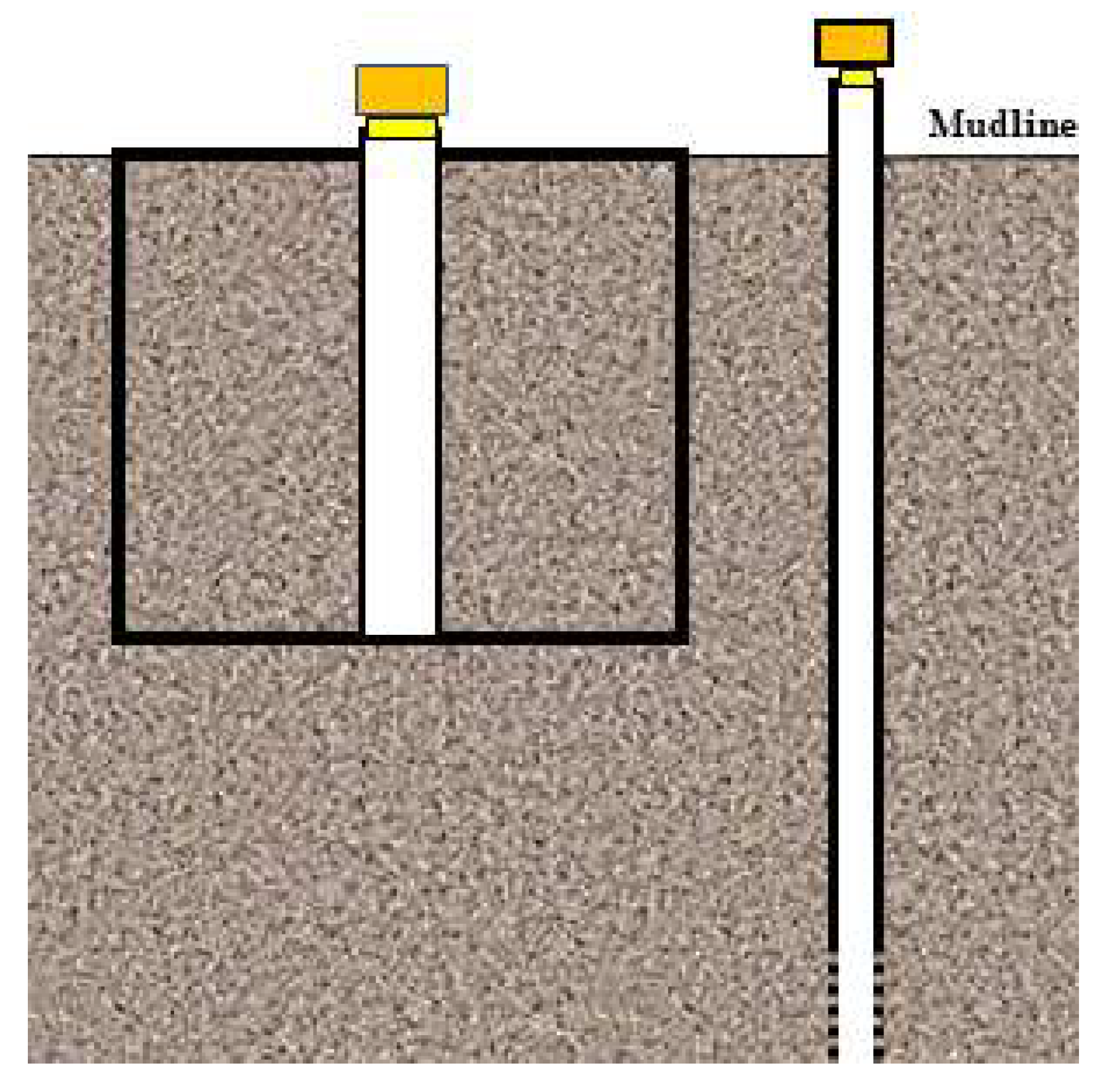
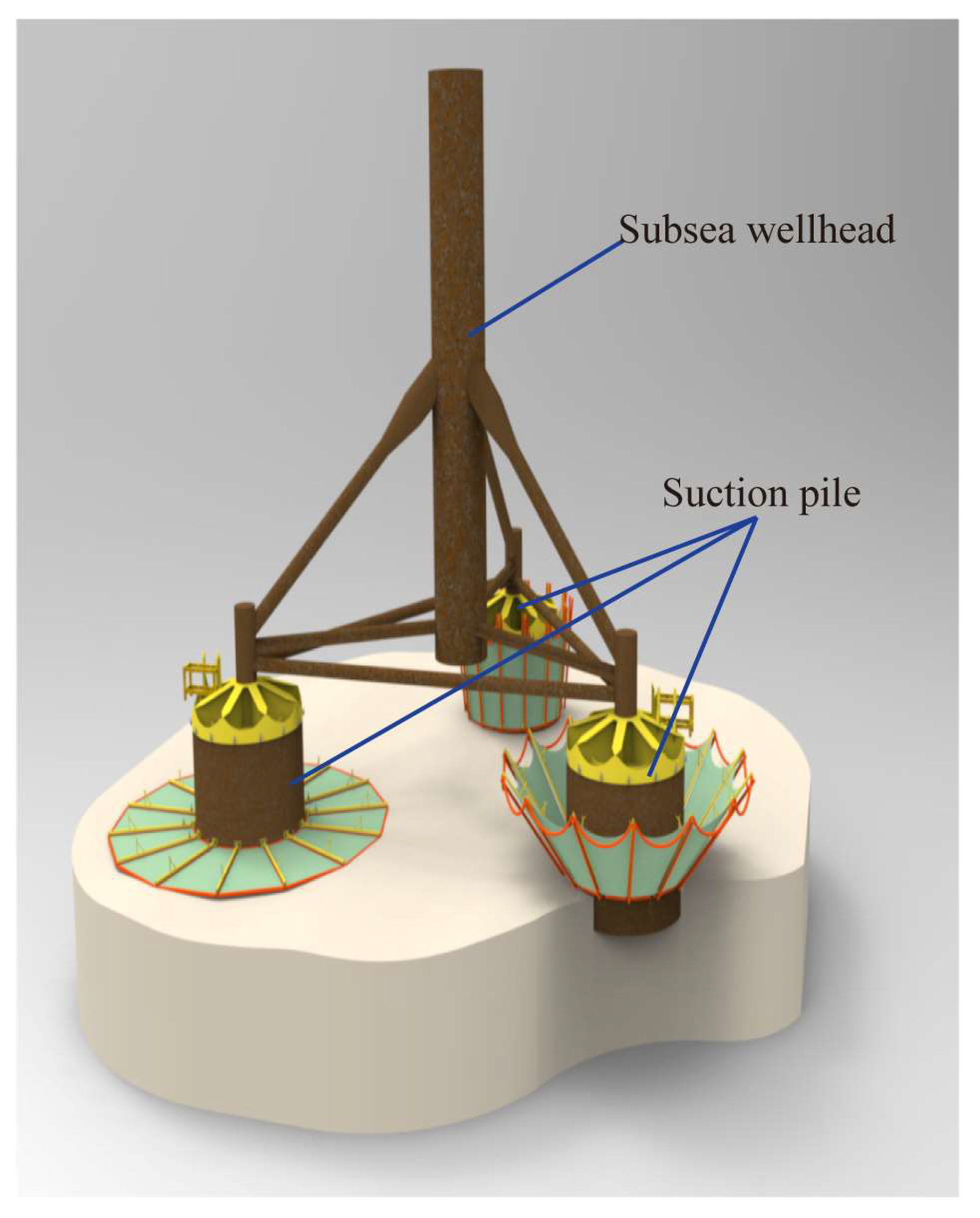
2. Conductor Suction Pile Structure and Force Analysis

2.1. Structure of Conductor Suction Pile

The conductor suction pile represents a composite structure that combines suction piles and surface conductors (Figure 3). The primary component comprises a large-diameter steel cylinder with an open bottom end and a closed top, within which a low-pressure wellhead head and a surface conductor are prefabricated. Additionally, two layers of reinforcement ribs, evenly distributed at 90° angles, are situated between the suction pile and the surface conductor, while the remaining space is filled with submarine soil.

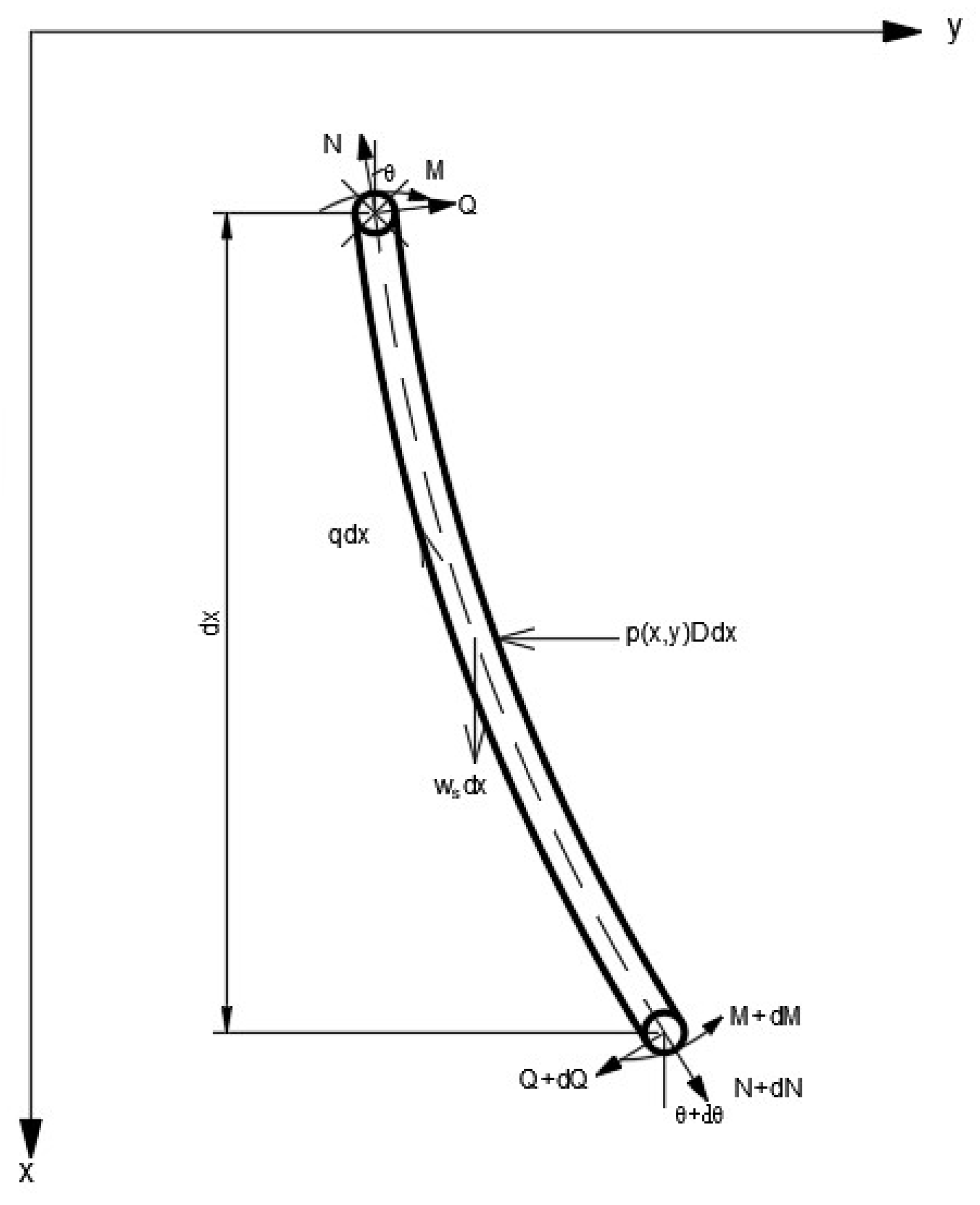
2.2. Force Analysis of Conductor Suction Pile

During the deepwater drilling process, once the suction pile is securely installed at the wellhead, the semi-submersible platform reaches the area above the conductor suction pile to commence the second spud drilling operation. Subsequently, the high-pressure wellhead and surface casing are lowered into the well and cemented in place. Following the completion of the second spud cementing operation, the riser system, along with the blowout preventer stacks (BOPs), is installed onto the high-pressure wellhead through the wellhead connector. Drilling fluid circulates through the riser system to the semi-submersible platform, facilitating the subsequent drilling and completion operations (Figure 4).
In this operational scenario, the installed suction pile system functions as a unified support for the wellhead. The forces acting on the conductor suction pile primarily originate from vertical and horizontal reactions at the spherical joint at the bottom of the riser, the gravity of the BOPs and suspended casing string, and lateral hydrodynamic forces acting on the BOPs and wellhead. These loads ultimately concentrate on the subsea wellhead, equivalent to vertical load Nt, horizontal load Ht, and lateral bending moment Mt. Under the influence of wellhead loads, the self-weight of the suction pile, and the weight of the soil inside the pile (W), the seabed exerts resistance on the conductor suction pile. This resistance includes vertical frictional resistance Qf, lateral soil reaction P, vertical bearing capacity at the pile tip Qp,b, and horizontal resistance at the seabed acting on the bottom of the pile Qb, among others (Figure 5).
During the drilling process, the conductor suction pile experiences composite loads, with horizontal loads being particularly minimal, leading to only minor displacements and deformations well below the point of structural failure. In studying the lateral bearing capacity characteristics under such conditions, it is reasonable to consider that the internal soil within the conductor suction pile moves along with the pile, treating the conductor suction pile as a unified entity [36,37,38]. As the primary focus is on the mechanical performance of the conductor suction pile, the surface conductor, ribs, and suction pile can be viewed as a system. This approach allows for an exploration of the overall displacement and bending moment distribution of the conductor suction pile system. Typically, the rib plate ranges from 0.1 m to 0.2 m in height, with a thickness of 1 inch, and exhibits a 90° distribution that is discontinuous both axially and radially. Consequently, we disregard the presence of the rib plate in the calculation process. The pile bottom resistance results from the soil’s resistance to lateral displacement at the pile end. This resistance primarily depends on the shear strength of the soil at the pile tip and is represented as a concentrated lateral shear force, denoted as Qb, acting at the pile tip. While flexible long piles can neglect Qb, its effect must be considered for rigid medium-to-short piles [39]. The cumulative effect of these forces may lead to pile sinking or tilting, and the entire pile is at risk of collapsing or experiencing overturning damage if the bending moment exceeds the design limit. Refer to Figure 5 for a mechanical calculation sketch of the conductor suction pile structure. The height of the surface conductor above the conductor suction pile’s top plate is denoted as Ha, while the height of the surface conductor below the conductor suction pile’s top plate is equal and represented as H.

3. Modeling and Solving

3.1. Basic Assumptions

To facilitate the investigation of the response characteristics of the suction pile surface conductor system, we make the following assumptions:
(1)
The force and deformation of the suction pile occur within the vertical plane, and the initial shape in the absence of deformation is vertical.
(2)
The material of the suction pile is homogeneous, isotropic, and linearly elastic.
(3)
Disregard the influence of the inclination of the suction pile on horizontal bearing capacity.
(4)
The internal soil within the suction pile moves in conjunction with the suction pile itself, excluding the effects of suction.
(5)
The rib of the suction pile is neglected.

3.2. Control Equations

The conductor suction pile system can be divided into two components (each subject to distinct external forces): the surface conductor above the mudline and the suction pile body below the mudline.
(1)
Surface conductor above the mudline
The surface conductor above the mudline is unaffected by the soil reaction forces (Figure 6), i.e., p(x, y) = 0 and q(x) = 0. By considering the equilibrium condition of the elemental segment of the surface conductor, the equilibrium differential equation can be expressed as follows:
d N d x + w a = 0
d 2 d x 2 [ E I d 2 y d x 2 ] N d 2 y d x 2 + w a d y d x = 0
(2)
Suction pile below the mudline
Based on the equilibrium condition of the elemental segment of the suction pile below the mudline, the equilibrium differential equation can be expressed as follows [7]:
d N d x + w s q = 0
d 2 d x 2 [ E I d 2 y d x 2 ] N d 2 y d x 2 + w s d y d x + p D = 0
where EI(x) is the bending stiffness varying along x direction; N(x) is the axial force varying along x direction; D(x) is the outer diameter of the suction pile; p(x, y) is the foundation reaction force per unit area; q(x) is the soil friction per unit length of the outer wall of the suction pile; and wa(x) and ws(x) are the weight per unit length of the conductor and the suction pile.

3.3. External Forces on the Conductor Suction Pile

The subsea suction pile is connected to the upper BOPs and the riser through the subsea wellhead. The forces exerted by the marine environment are transmitted to the subsea wellhead through the riser, subjecting it to vertical, lateral, and bending forces, which are complex in deepwater environments. To simplify the analysis, we assume that the lateral load Ht, bending moment Mt, and vertical force Nt acting on the top (wellhead) of the conductor are known.

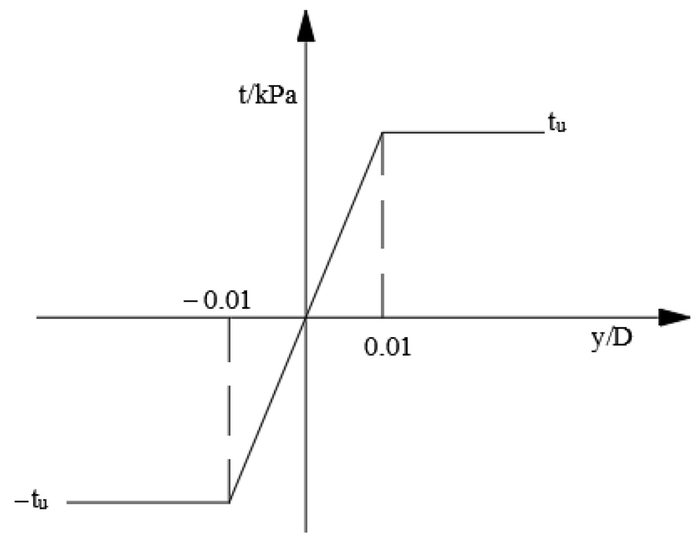
3.4. Interaction Force between Conductor Suction Pile and Subsea Soil

The seabed soil provides restraint to the conductor suction pile system, and interaction forces exist between the soil on the suction pile side and tip with the suction pile body.
(1)
Axial and lateral soil forces on the suction pile side:
The nonlinear forces between the pile body and the subsea soil, especially for large-diameter suction piles under complex loads, are calculated using the theoretical equations outlined in the widely adopted API RP 2A-WSD 2014 specification [34]. This specification provides guidelines for determining P–y and Q–z curves specifically for clay soils.
(2)
Lateral soil force at the suction pile tip:
For large-diameter suction piles subjected to lateral loads, the lateral load transfer curve at the suction pile tip is typically determined through field tests. In this study, we employ a simplification based on the analogy with the straight shear test and the specifications provided by API for sand and clay soils. The relationship curve between the average shear stress acting on the pile tip and the lateral displacement of the pile tip is illustrated in Figure 7. The average shear stress, denoted as “tb”, exhibits a linear variation when the lateral displacement of the pile tip is less than 0.01 D (where D is the pile diameter), and reaches the limiting value “tu” when it is greater than or equal to 0.01 D [39].
The lateral concentrated force acting at the suction pile tip is:
Q b = A b t b
where Ab represents the suction pile end area and tb denotes the average shear stress at the suction pile tip, which can be calculated according to the following equation:
t u = σ v tan φ f o r s a n d s o i l c u f o r c l a y s o i l
where σ v is the overburden pressure at the suction pile tip (kPa), φ is the internal friction angle of sandy soil (°), and c u is the undrained shear strength of clayey soil (kPa).

3.5. Bending Stiffness

The equivalent bending stiffness of the surface conductor above the top plate of the suction pile is given by the following:
K 1 = E s t I s c
The conductor suction pile assemblage is a multi-layered tubular structure consisting of suction pile, clay soil, and surface conductor, with an equivalent flexural stiffness of:
K 2 = E s t ( I h + I s c ) + E s I s
where Est and Es are the modulus of elasticity of steel and subsea soil; Isc, Ih, and Is are the cross-sectional moments of inertia of surface conductor, conductor pile, and subsea soil.

3.6. Boundary Conditions and Continuity Conditions

The vertical force, lateral force, and bending moment at the top of the conductor suction pile are known. At the bottom of the conductor suction pile, the bending moment is zero, and the relationship between shear force and displacement is known. The conductor suction pile is required to be continuous at the mud line. The boundary conditions and continuity conditions are as follows:
M ( H a ) = M t Q ( H a ) = H t N ( H a ) = N t M ( H ) = 0 Q ( H ) = Q b
y ( 0 + ) = y ( 0 ) y ( 0 + ) = y ( 0 ) Q ( 0 + ) = Q ( 0 ) M ( 0 + ) = M ( 0 ) N ( 0 + ) + w c = N ( 0 )
where Qb is the concentrated shear force at the bottom of the conductor suction pile; wc is the equivalent concentrated load at the top plate of the pile.

3.7. Solution of the Problem

To solve the lateral displacement response of the conductor suction pile system at the wellhead, the following substitution is introduced:
d y d x = tan θ d θ d x = M E I cos 2 θ
The governing equations for the upper and lower sections of the conductor suction pile system along the mudline are transformed into their respective sets of first-order differential equations:
Surface conductor segmentation above the mudline (−Hax < 0):
d y d x = tan θ d θ d x = M E I cos 2 θ d M d x = Q d Q d x = N M E I w a tan θ d N d x = w a
Conductor suction pile segmentation below the mudline ( 0 x H ):
d y d x = tan θ d θ d x = M E I cos 2 θ d M d x = Q d Q d x = N M E I w s tan θ p D d N d x = q w s
The entire solution region comprises two sub-regions, each with five first-order differential equations to be solved, requiring ten known conditions. Simultaneously, we have ten boundary conditions at the top of the surface conductor, the bottom of the conductor suction pile, and the continuity conditions along the mud surface line, leading to a solvable problem. Consequently, a four-stage Lobatto IIIa configuration method program for the multipoint edge value problem was developed using MATLAB 2023a to find the solution of the conductor suction pile system.
In cases where the pile bottom displacement is approximately zero (e.g., less than 0.1 mm), the highest position continuously less than this specified value is searched in the solution, and this position can be considered as the embedment point. However, if the pile bottom displacement exceeds the specified value, we initiate a search starting from the mud line. We look for the calculation point along the mud penetration depth where the product of the displacement of two adjacent points is less than zero, and through a linear interpolation of these two points, we obtain the position of the rotation center.

4. Application Examples and Analysis of Influencing Factors

A semi-submersible drilling platform was utilized for drilling and completing operations in a specific deepwater natural gas hydrate well. Under environmental loads, platform offset, and other operational loads during drilling conditions, the wellhead experienced 2700 kN∙m of equivalent bending moment, 180 kN of horizontal force, and 1800 kN of vertical force. By considering the basic parameters of typical conductor suction piles and with reference to typical soil conditions in the sea, the study investigated the influence of the acting load and soil characteristic parameters on the deflection and deformation, bending moment, and the point of no lateral displacement of the conductor suction piles.

4.1. Basic Parameters of Conductor Suction Pile

Table 1 presents the basic parameters of the deepwater conductor suction pile. Moreover, it is known that the weight per unit length of the surface conductor is 11.4 kN/m, the weight per unit length of the pile body is 47.1 kN/m, and the weight of the suction pile’s top plate is 91 kN. For simplification, it is assumed that the seabed within the length range of the suction pile consists of a uniform clay layer with a submerged unit weight of 7.0 kN/m3 and a shear strength of 18 kPa.

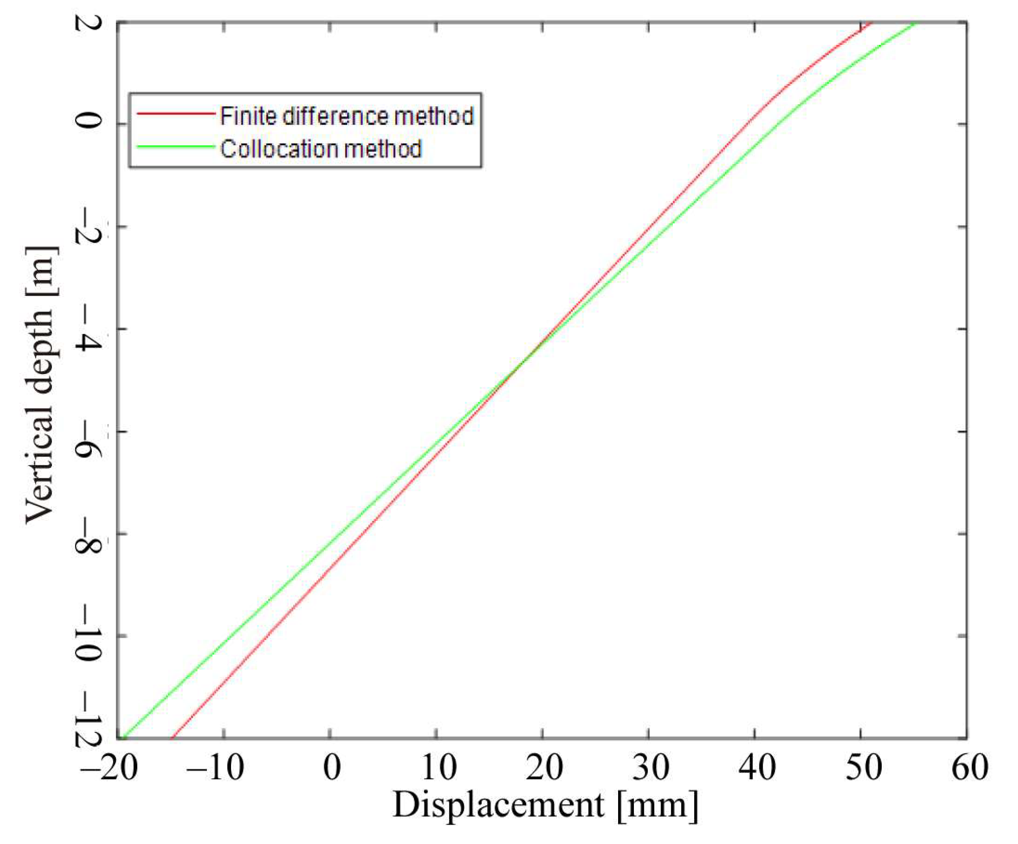
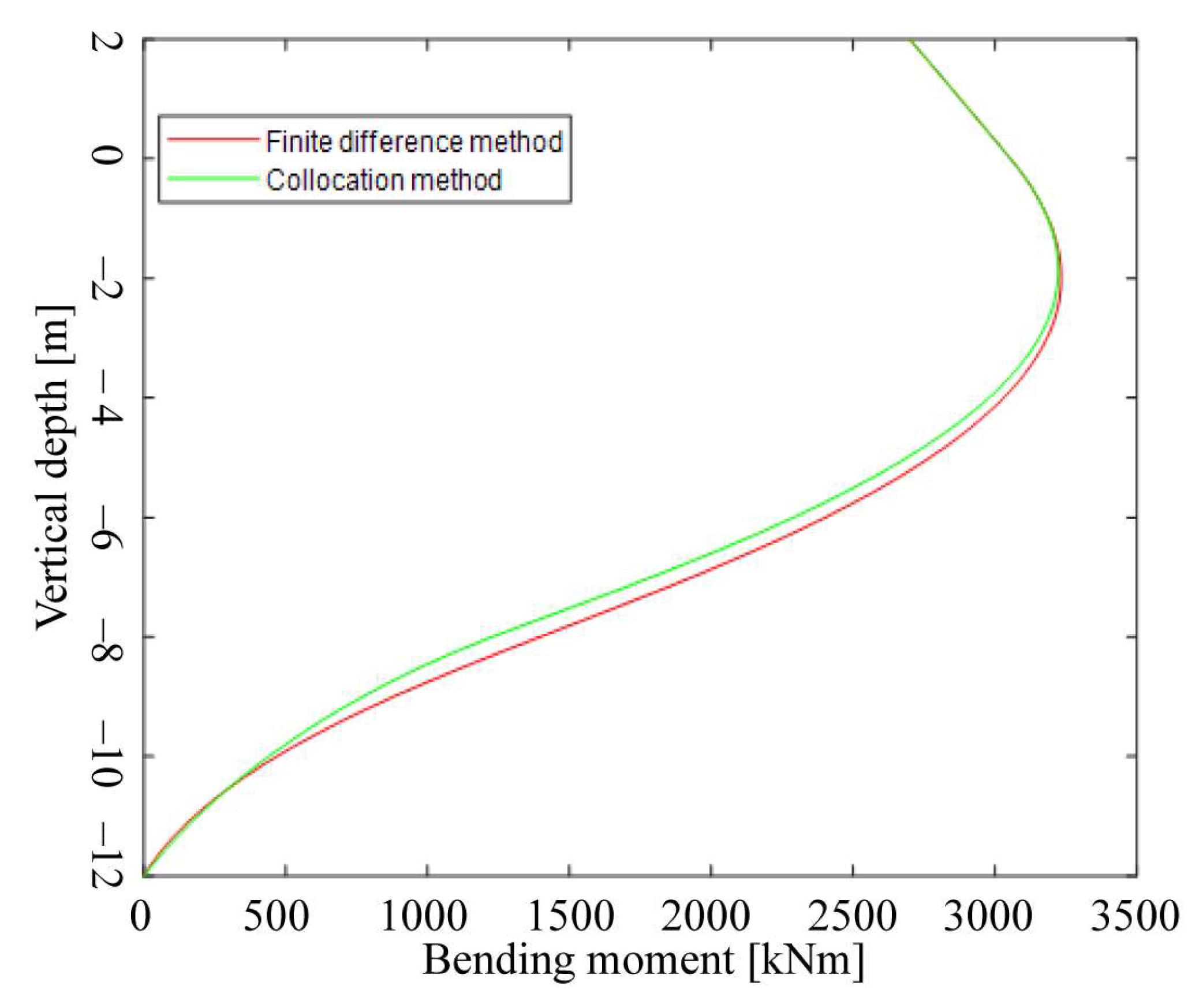
4.2. Configuration Method Validation

To verify the accuracy of the proposed method, the computed results were compared with those obtained using the finite difference method. Both methods considered the interaction between the suction pile and the soil using the p–y curve, with a finite difference spacing of 0.05 m. As depicted in Figure 8 and Figure 9, it is evident that the results obtained from the two methods are in excellent agreement. The proposed method, relying on the direct solution of differential equations, yields more precise results. The locations of the rotation centers obtained from the proposed method and the finite difference method are 8.16 m and 8.23 m, respectively, indicating that the center of rotation position obtained by the finite difference method is deeper into the soil.

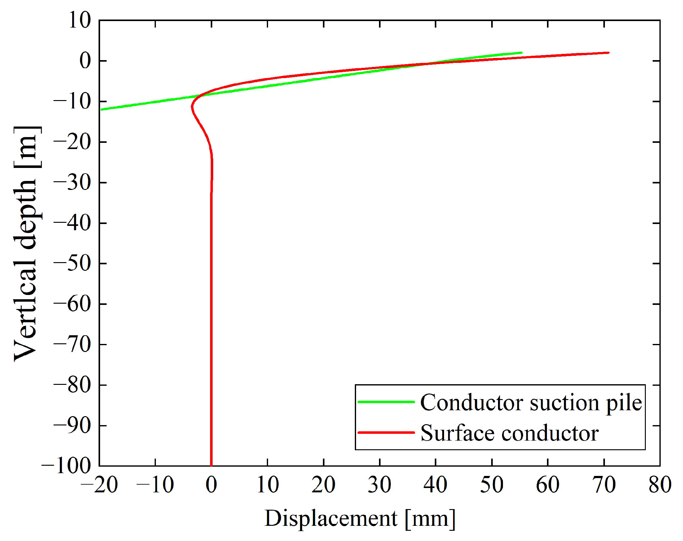
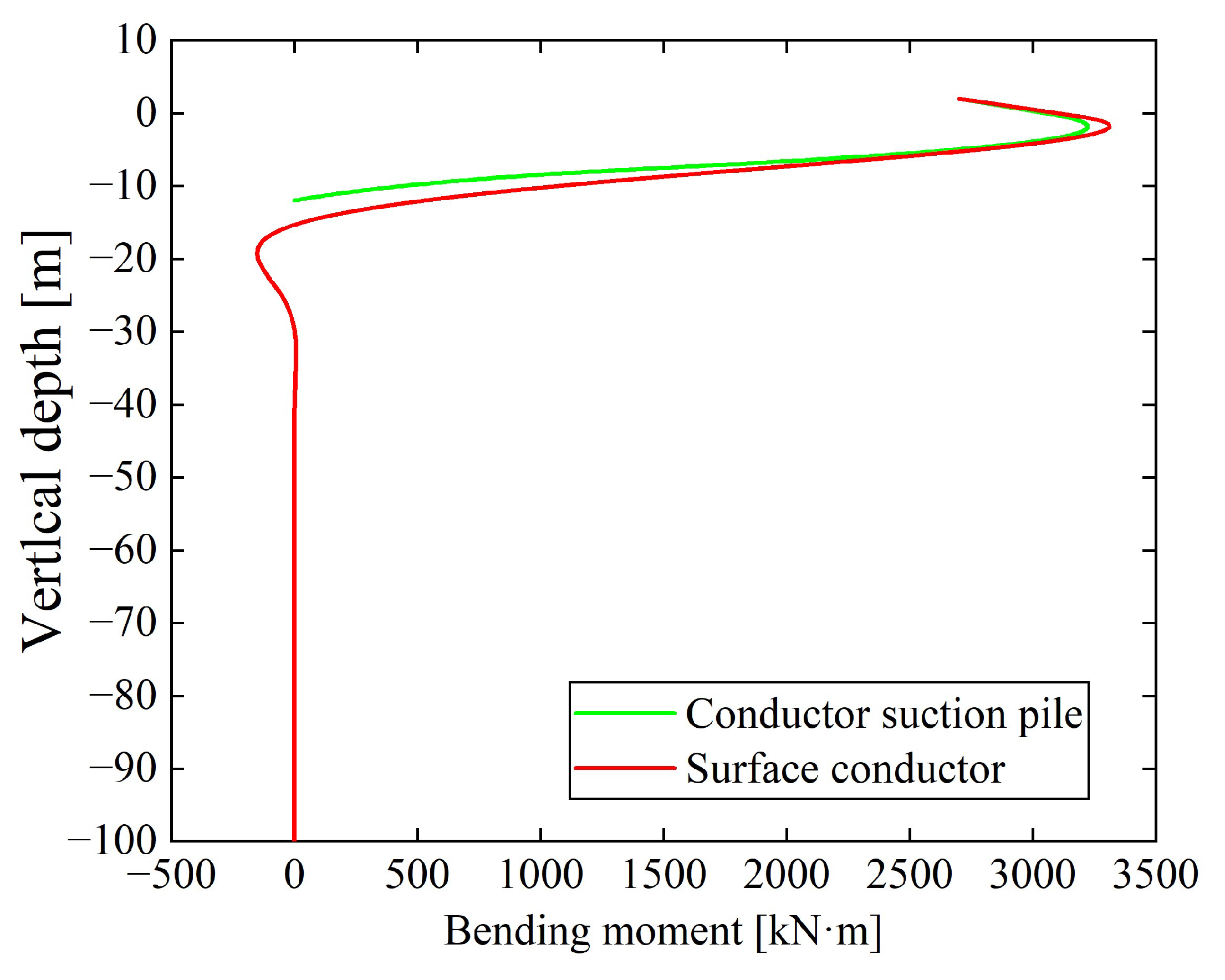
4.3. Comparison of Conductor Suction Pile and Surface Conductor Results

Replacing the surface conductor with a conductor suction pile for surface well construction demonstrates significant advantages in wellhead lateral stability. Using the surface conductor lateral stability model based on the Winkler beam by Li et al., the lateral stability characteristics of a 0.9144 m diameter surface conductor installed by jetting under the same operational conditions were calculated [40]. The surface conductor’s penetration depth was 100 m, and the results by Li et al. indicated that lateral displacement and bending moment remained constant and close to zero below 35 m. Figure 10 presents the depth–displacement curves for the conductor suction pile and surface conductor. The lateral displacement of the conductor suction pile changes approximately as a straight line with depth, reaching its maximum at the top and decreasing to zero before reversing and increasing again. In contrast, the surface conductor’s lateral displacement initially follows a trend similar to the conductor suction pile but decreases after reversing, approaching zero and remaining stable. The maximum lateral displacement for the conductor suction pile is 55.32 mm at the top, while for the surface conductor, it is 70.81 mm, representing a reduction of 21.88%. Referring to rigid short piles, a horizontal displacement of 3–6% of the diameter is considered the failure criterion for conductor suction piles [41]. Taking 6% D as the horizontal limit displacement, i.e., 0.36 m, it is evident that the conductor suction pile’s horizontal displacement is far below the failure standard. Figure 11 displays the depth–bending moment curves for the conductor suction pile and surface conductor. Both exhibit similar patterns of increasing and then decreasing bending moment in the shallow layers, but the surface conductor increases again after reaching zero, decreases, and stabilizes. The maximum bending moment for the conductor suction pile occurs around 2 m below the mudline, slightly less than 3200 kN·m, whereas the surface conductor’s flexural stiffness is 8.52 MN·m, considerably lower than the conductor suction pile’s flexural stiffness of 253 MN·m. Overall, the conductor suction pile demonstrates a higher lateral bearing capacity and a lower risk of wellhead instability compared to the surface conductor.

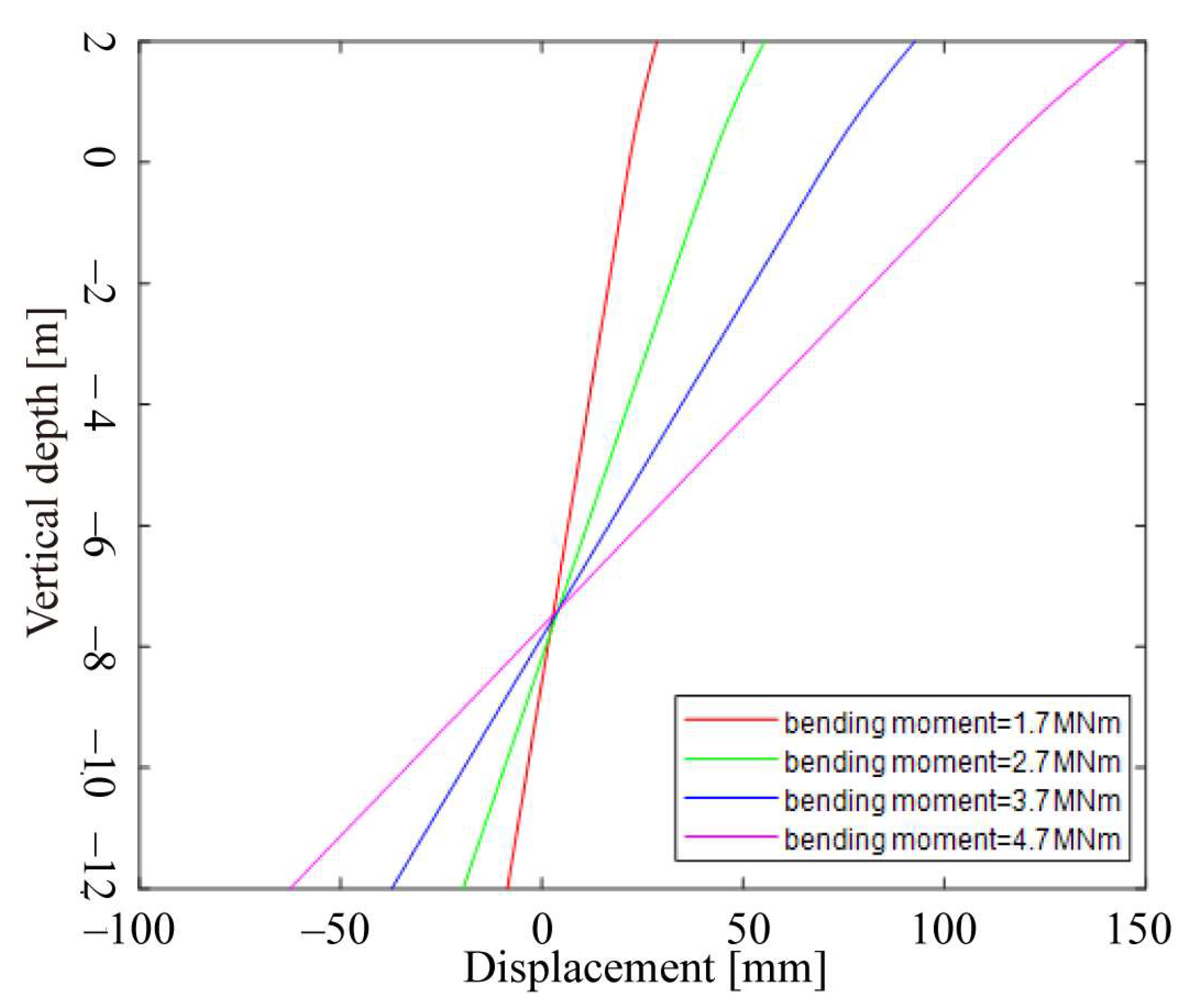
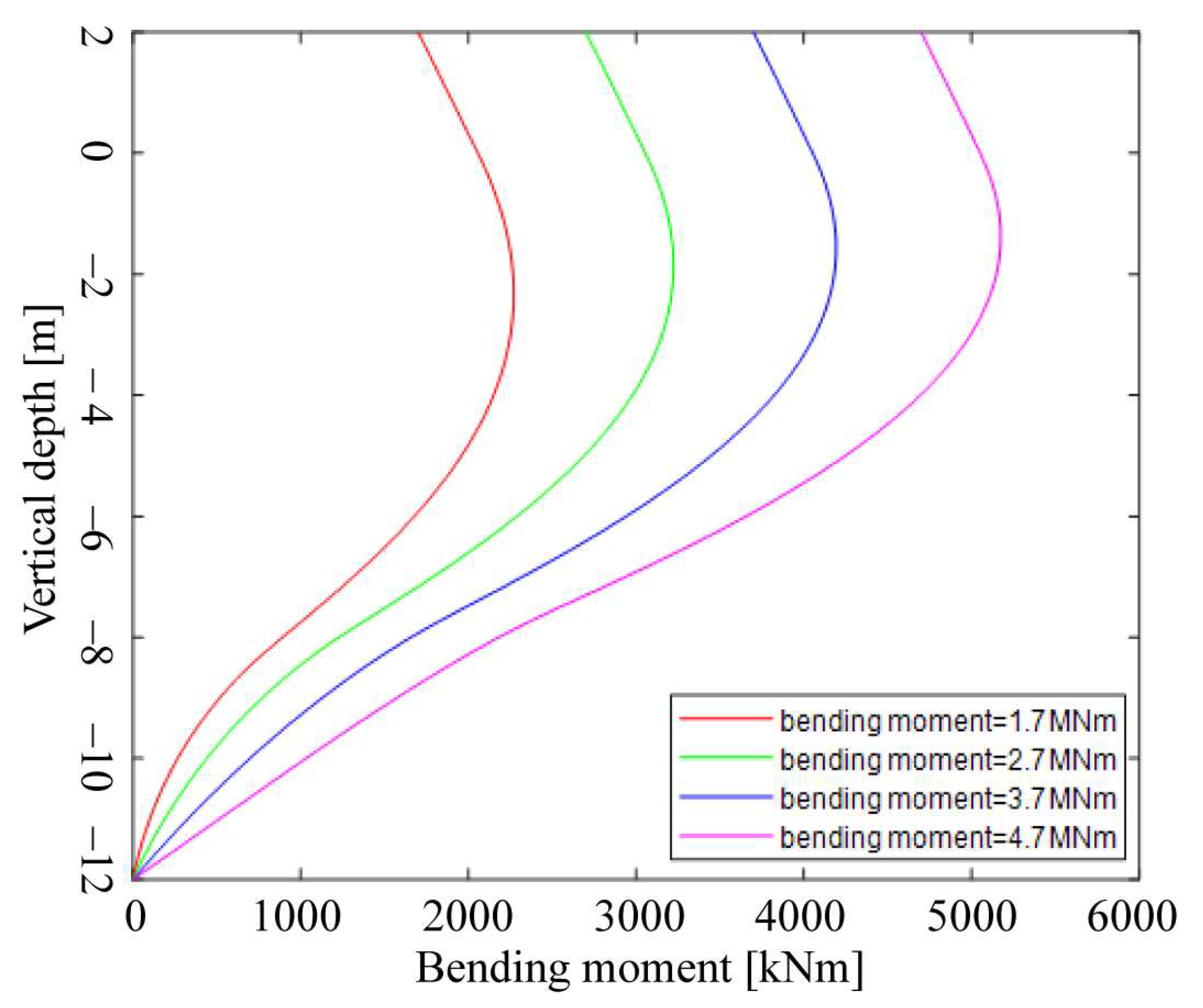
4.4. Influence of Wellhead Forces on Lateral Load-Bearing Performance of Conductor Suction Piles

Figure 12 and Figure 13 depict the displacement and bending moment curves of the conductor suction pile under varying magnitudes of bending moment at the wellhead. Notably, as the wellhead bending moment increases, both the lateral displacement and bending moment of the conductor suction pile, as well as the top conductor, experience a corresponding increase. Even under the influence of a wellhead moment of 4.7 MN∙m, the conductor suction pile exhibits a maximum displacement of 145 mm and a maximum bending moment of 5.17 MN·m. These values are significantly below the corresponding failure thresholds, highlighting the exceptional bending resistance of the device. Additionally, under bending moments of 1.7 MN∙m, 2.7 MN∙m, 3.7 MN∙m, and 4.7 MN∙m, the suction pile undergoes rotation. The ratio of the rotation center to pile length was found to be 0.71, 0.68, 0.65, and 0.64, respectively, indicating that the rotation center approaches the top of the suction pile with the application of higher loads. It is noteworthy that the lateral displacement at the top of the conductor is the most pronounced, while the bending moment of the suction pile reaches its peak value at a depth of approximately 2 m below the mudline. Subsequently, the bending moment rapidly decreases with penetration depth.

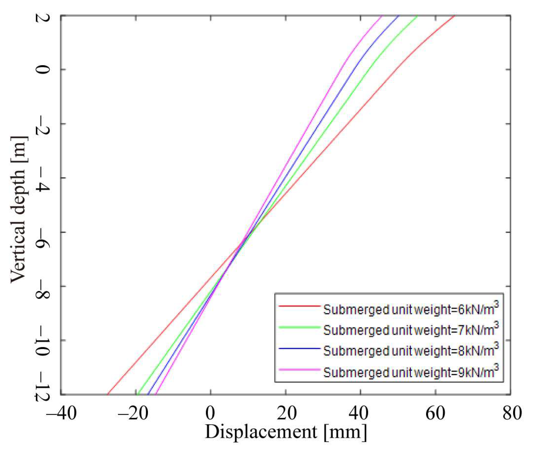
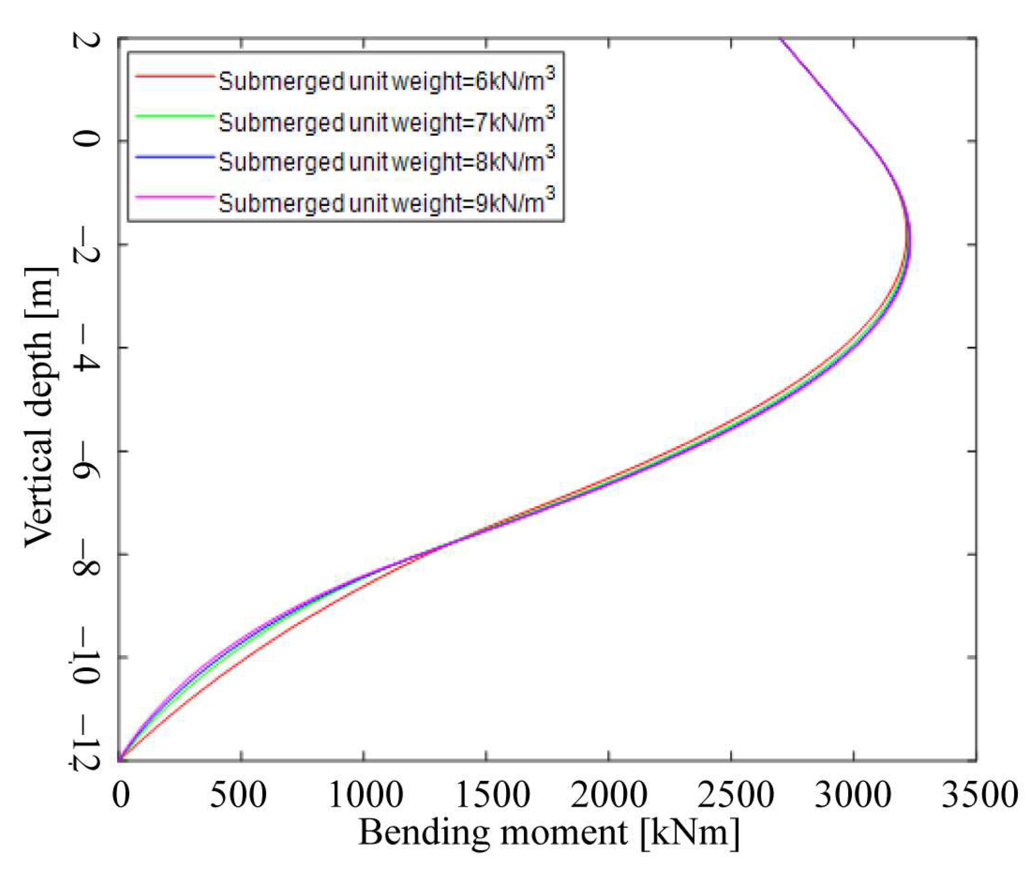
4.5. Influence of Subsea Soil Properties on Lateral Bearing Performance of Conductor Suction Piles

Figure 14 and Figure 15 display the calculated results of lateral displacement and bending moment of the conductor suction pile under different submerged unit weights of clay seabed soil. The key physical properties of clay soil considered are the submerged unit weight and undrained shear strength. The results demonstrate that the lateral displacement of the conductor suction pile diminishes as the submerged unit weight increases. Specifically, at submerged unit weights of 6.0 kN/m3, 7.0 kN/m3, 8.0 kN/m3, and 9.0 kN/m3, the conductor suction pile undergoes rotation, with the ratio of the rotation center to pile length being 0.64, 0.68, 0.69, and 0.70, respectively. Moreover, the rotation center tends to shift toward the bottom of the pile with an increase in the submerged unit weight. On the other hand, it is noted that the submerged unit weight has minimal influence on the bending moment of the conductor suction pile.
Figure 16 and Figure 17 illustrate the computed results of lateral displacement and bending moment of the conductor suction pile under various undrained shear strengths of clay seabed soil. The findings reveal that as the undrained shear strength increases, both the lateral displacement and bending moment of the conductor suction pile decrease. Specifically, at undrained shear strengths of 13 kPa, 18 kPa, 23 kPa, and 28 kPa, the conductor suction pile undergoes rotation, with the ratio of the rotation center to pile length being 0.65, 0.68, 0.69, and 0.50, respectively. Notably, when the undrained shear strength is 28 kPa, the lateral deformation is smaller compared to the previous three cases. This is because the soil surrounding the pile has reached half of its ultimate soil resistance, resulting in a significant increase in the actual soil resistance acting on the conductor suction pile. Consequently, the rotation center moves closer to the top of the conductor suction pile.

5. Conclusions

(1)
An analysis model for the deepwater drilling conductor suction pile system was established based on the principles of pile foundation theory and structural mechanics. The governing equations were subsequently transformed into a system of first-order differential equations. To solve the model numerically, a MATLAB program employing the four-stage Lobatto IIIa collocation method was developed.
(2)
Compared to the traditional surface conductor, under the same wellhead loads, the conductor suction pile exhibits a reduction of 21.88% in maximum horizontal displacement and lower maximum bending moment. Furthermore, both values are far below the conductor suction pile’s limit horizontal displacement and flexural stiffness (failure state). This clearly demonstrates that the conductor suction pile possesses a higher lateral bearing capacity and a lower operational risk compared to the surface conductor in natural gas hydrate extraction.
(3)
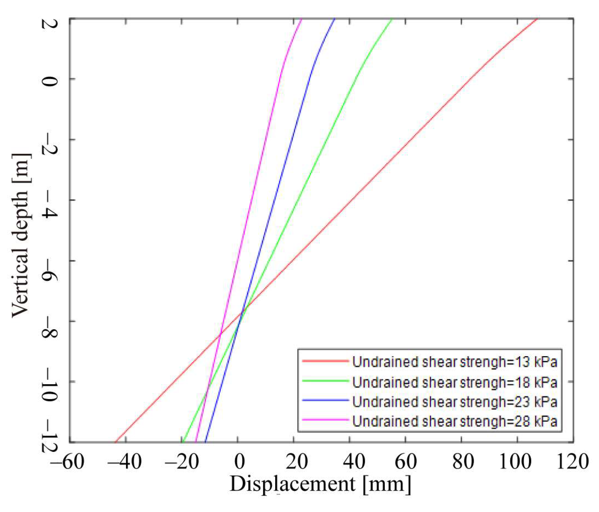
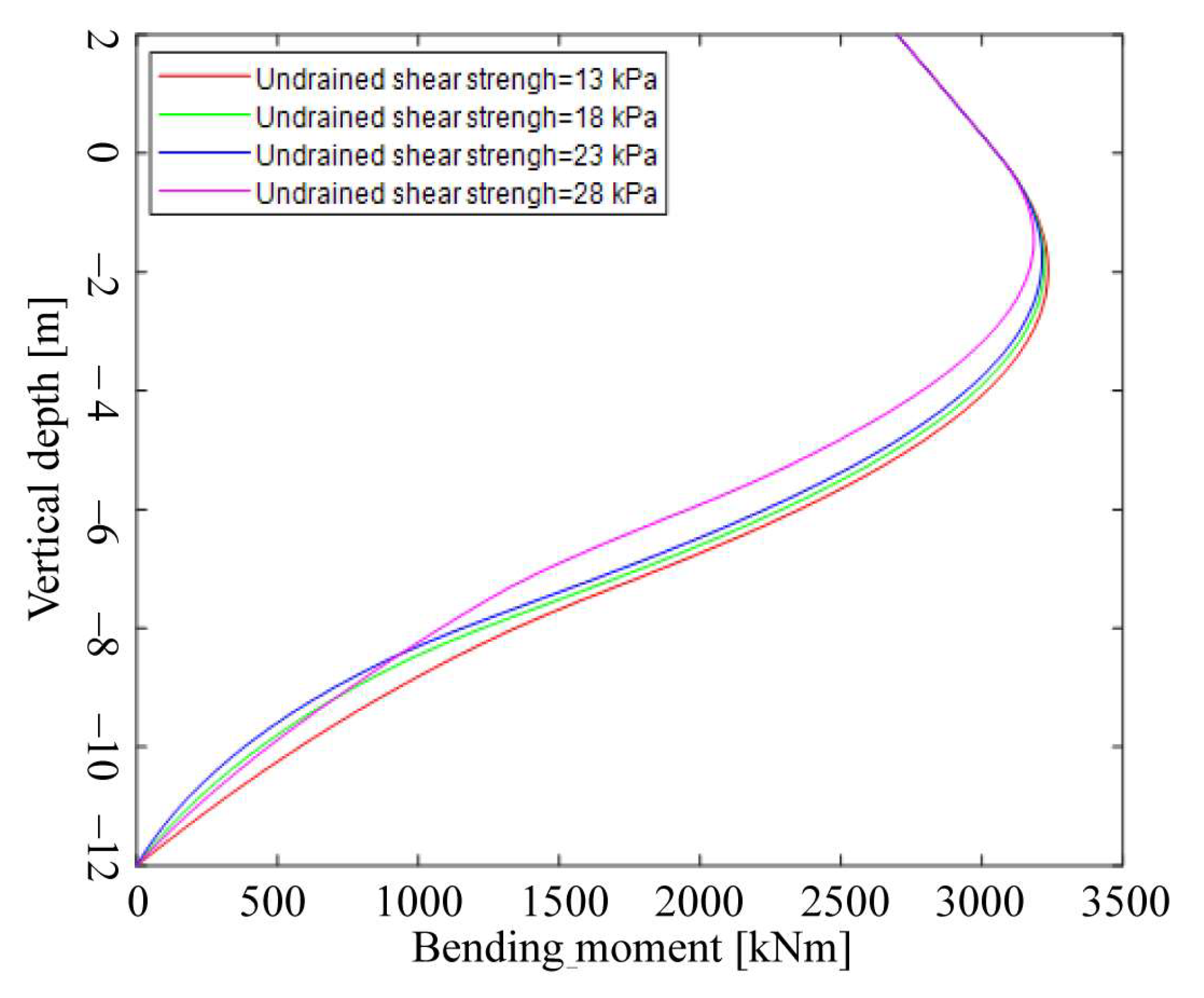
The analysis demonstrates that as the wellhead moment increases, both the lateral displacement and bending moment of the conductor suction pile increase, and the rotation center shifts upward. Conversely, with an increase in submerged unit weight, the lateral displacement of the conductor suction pile decreases, while the change in bending moment is minimal, and the rotation center shifts downward. Moreover, a higher soil shear strength results in smaller lateral displacement and bending moment for the conductor suction pile, with the rotation center shifting upward.

Author Contributions

S.L.: Conceptualization, data curation, formal analysis, methodology, writing—original draft, writing—review and editing. J.Y.: Conceptualization, Funding acquisition, Methodology, Project administration, Resources, Supervision. G.Z.: Data curation, software. J.W.: Formal analysis, Validation. Y.H.: Conceptualization, Investigation, Resources. K.J.: Visualization, Writing—original draft. All authors have read and agreed to the published version of the manuscript.

Funding

This research was funded by the National Natural Science Foundation of China, grant number U22B20126; National Key Research and Development Program, grant number 2022YFC2806100 and National Ministry of Industry and Information Technology Innovation Special Project, grant number 2020-HGCBGXZG-ZX-GCFW-1780.

Data Availability Statement

Data are contained within the article.

Acknowledgments

The authors gratefully acknowledge the CNOOC China Limited, Zhanjiang Branch of data support.

Conflicts of Interest

Author Yi Huang was employed by the company CNOOC China Limited, Zhanjiang Branch. The remaining authors declare that the research was conducted in the absence of any commercial or financial relationships that could be construed as a potential conflict of interest.

References

  1. Bazaluk, O.; Sai, K.; Lozynskyi, V.; Petlovanyi, M.; Saik, P. Research into dissociation zones of gas hydrate deposits with a heterogeneous structure in the Black Sea. Energies 2021, 14, 1345. [Google Scholar] [CrossRef]
  2. Klymenko, V.; Ovetskyi, S.; Martynenko, V.; Vytyaz, O.; Uhrynovskyi, A. An alternative method of methane production from deposits of subaquatic gas hydrates. Min. Miner. Depos. 2022, 16, 11. [Google Scholar] [CrossRef]
  3. Quirós, G.; Little, R. Deepwater soil properties and their impact on the geotechnical program. In Proceedings of the Offshore Technology Conference, Houston, TX, USA, 5–8 May 2003. [Google Scholar]
  4. Akers, T.J. Jetting of structural casing in deepwater environments: Job design and operational practices. SPE Drill. Complet. 2008, 23, 29–40. [Google Scholar] [CrossRef]
  5. Su, K.H.; Guan, Z.C.; Long, Z.H. Impact of the seabed soil properties on the stability of subsea wellhead for deepwater drilling. Oil Drill. Prod. Technol. 2012, 34, 7–10. [Google Scholar]
  6. Su, K.H.; Guan, Z.C.; Su, Y.N. Mechanical stability analysis of subsea wellhead for deepwater drilling. Oil Drill. Prod. Technol. 2008, 30, 1–4. [Google Scholar]
  7. Guan, Z.H.; Su, K.H.; Su, Y.N. Analysis on lateral load-bearing capacity of conductor and surface casing for deepwater drilling. Acta Pet. Sin. 2009, 30, 285–290. [Google Scholar]
  8. Jizu, X.U.; Qingzeng, S.H.I.; An, S.O.N.G.; Hongyan, D. The first application and design of suction anchor in domestic offshore engineering. China Offshore Oil Gas (Eng.) 1995, 7, 32–36. [Google Scholar]
  9. Hunag, S.T.; Wang, H.C.; Liu, B.; Nie, X.M.; Jiang, Z.L. Installation technology of LvDa 32-2mop suction pile platform. China Shipbuild. 2012, 53, 184–188. [Google Scholar]
  10. Liang, G.Q.; Qi, J.L.; Wu, B.B.; Duan, L.Z.; Hu, S.F. Application of deep-water suction anchor in Liuhua 16-2 project. China Pet. Chem. Ind. Stand. Qual. 2021, 41, 85–86. [Google Scholar]
  11. Nole, M.; Daigle, H.; Cook, A.E.; Malinverno, A.; Flemings, P.B. Burial-driven methane recycling in marine gas hydrate systems. Earth Planet. Sci. Lett. 2018, 499, 197–204. [Google Scholar] [CrossRef]
  12. Zhang, B.; Pan, Z.; Cao, L.; Xie, J.; Chu, S.; Jing, Y.; Lu, N.; Sun, T.; Li, C.; Xu, Y. Measurement of wellbore leakage in high-pressure gas well based on the multiple physical signals and history data: Method, technology, and application. Energy Sci. Eng. 2024, 12, 4–21. [Google Scholar] [CrossRef]
  13. Shaker, S.S.; Services, G.A. A New Perspective on Shallow Water Flow (SWF) Prediction and the Prevention of Sinking Well-Heads in Deepwater Settings. Recorder 2015, 40, 34–40. [Google Scholar]
  14. Zhang, J.H.; Sun, G.L.; Yan, D.; Lu, X.B. Geotechnical centrifugal simulation research and analysis of suction foundation of offshore platform. Ocean Eng. 2004, 22, 90–97. [Google Scholar]
  15. Liu, J.B.; Li, Y.F.; Liu, J.D. Finite element analysis of soil plug formation during suction anchor sinking. Water Sci. Eng. Technol. 2007, 03, 39–42. [Google Scholar]
  16. Liu, X.K.; Lu, Q.; Lu, S.W.; Liu, C.L.; Guo, S.L. Vacuum penetration and ultimate uplift bearing capacity of low skirt suction pile. Geotech. Mech. 2018, 39, 2089–2098. [Google Scholar]
  17. Wang, P.; Wang, X.F.; Zhang, X.F. Finite element analysis of bearing characteristics of deep-water suction anchor foundation in clay. Constr. Technol. 2019, 48, 24–28. [Google Scholar]
  18. Liu, S.J.; Huang, Y.; Liu, H.X.; Zhang, M.H.; Li, L.; Zheng, J.L. Experimental study on well construction process and bearing capacity characteristics of deepwater conductor suction pile. China Pet. Mach. 2022, 50, 32–41. [Google Scholar]
  19. Liu, S.J.; Huang, Y.; Zhang, M.H.; Li, S.Z.; Fu, C.; Zhu, G.J. Study on the subsea wellhead stability of suction bucket foundation. China Offshore Oil Gas 2022, 34, 132–140. [Google Scholar]
  20. Hogervorst, J. Field trails with large diameter suction piles. In Proceedings of the Offshore Technology Conference, Houston, TX, USA, 5–8 May 1980. [Google Scholar]
  21. Steensen-Bach, J. Recent model tests with suction piles in clay and sand. In Proceedings of the Offshore Technology Conference, Houston, TX, USA, 7–10 May 1992. [Google Scholar]
  22. Li, D.Y.; Feng, L.Y.; Zhang, Y.K.; Guo, Y.X. Model tests on lateral bearing capacity and deformation of skirted suction caissons in saturated fine sand under horizontal monotonic loading. Chin. J. Geotech. Eng. 2013, 35, 2030–2037. [Google Scholar]
  23. Conte, E.; Pugliese, L.; Troncone, A.; Vena, M. A simple approach for evaluating the bearing capacity of piles subjected to inclined loads. Int. J. Geomech. 2021, 21, 04021224. [Google Scholar] [CrossRef]
  24. Liu, Y.; Li, S.Z.; Sun, G.D.; Liu, R.; Yin, F.; Zhou, L.; Shi, L.; Wang, Y.W.; Song, Y.R. Model test and numerical simulation study on bearing performance of conductor suction pile foundation. China Offshore Oil Gas. 2022, 34, 194–202. [Google Scholar]
  25. Wang, X.; Li, D.; Li, J. Centrifuge modeling and numerical analysis on lateral performance of mono-bucket foundation for offshore wind turbines. Ocean Eng. 2022, 259, 111925. [Google Scholar] [CrossRef]
  26. Faul, G.; Audibert, J.; Hamilton, T. Using suction technology for deep installation of structural pipe in deepwater. In Proceedings of the SPE/IADC Drilling Conference and Exhibition, Dallas, TX, USA, 3–6 March 1998. [Google Scholar]
  27. Sivertsen, T.; Strand, H. New well foundation concept, as used at a Norwegian Sea well. In Proceedings of the SPE Arctic and Extreme Environments Conference and Exhibition, Moscow, Russia, 18–20 October 2011. [Google Scholar]
  28. Mathis, W.; Strand, H.; Hollinger, G. Case history: How to enable the horizontal development of shallow reservoirs. In Proceedings of the SPE/IADC Drilling Conference and Exhibition, The Hague, The Netherlands, 14–16 March 2017. [Google Scholar]
  29. Kan, C.; Yang, J.; Yu, X.; Dong, T.; Wu, X.; Liu, M.; Li, C.; Zhang, C.; Fu, J. Load bearing characteristics study on novel deepwater composite drilling conductor by simulation and experimental methods. J. Pet. Sci. Eng. 2018, 171, 289–301. [Google Scholar] [CrossRef]
  30. Yang, J.; Zhu, G.J.; Li, S.Z.; Li, L.; Guan, S.; Song, Y. Research on well construction model of deep sea resource drilling with suction pile. Pet. Drill. Tech. 2023, 51, 134–139. [Google Scholar]
  31. Li, S.Z.; Yang, J.; Zhu, G.J.; Li, Z.; Wang, N. Prediction of minimum depth of conductor anchor node in deep-water drilling. Pet. Drill. Tech. 2023, 51, 29–36. [Google Scholar]
  32. Matlock, H. Correlation for design of laterally loaded piles in soft clay. In Proceedings of the Offshore Technology Conference, Houston, TX, USA, 22–24 April 1970. Paper Number: OTC-1204-MS. [Google Scholar]
  33. Reese, L.C.; Cox, W.R.; Koop, F.D. Analysis of laterally loaded piles in sand. In Proceedings of the Offshore Technology Conference, Houston, TX, USA, 6–8 May 1974. Paper Number: OTC-2080-MS. [Google Scholar]
  34. API Recommended Practice 2GEO/ISO 19901-4; Geotechnical and Foundation Design Considerations. American Petroleum Institute (API): Washington, DC, USA, 2011.
  35. American Petroleum Institute (API). API Recommended Practice 2A-WSD. Recommended Practice for Planning, Designing and Constructing Fixed Offshore Platforms-Working Stress Design, 1st ed.; American Petroleum Institute (API): Washington, DC, USA, 2014. [Google Scholar]
  36. Liu, M.M. Bearing Capacity and Optimization Design of Composite Bucket Foundation for Offshore Wind Turbine. Master’s Thesis, Tianjin University, Tianjin, China, 2011. [Google Scholar]
  37. Mohiuddin, M.; Ullah, S.; Hossain, M.; Kim, Y.; Hu, Y.; Ragni, R. Soil failure mechanisms during installation and inclined pullout of stiffened suction caisson in calcareous silt. Appl. Ocean Res. 2022, 125, 103249. [Google Scholar] [CrossRef]
  38. Qiu, C.; Wang, W.; Yan, Y.; Fu, D.; Yan, S. The optimisation of anti-overturning capacities for tripod suction bucket foundations in clay manuscript submitted to ocean engineering. Ocean Eng. 2022, 264, 112496. [Google Scholar] [CrossRef]
  39. Zhai, E.D.; Shi, S.G.; Hu, Z.B.; Xu, C.S. An analytical method for laterally loaded large-diameter steel pipe piles based on load-transfer curves. Chin. J. Rock Mech. Eng. 2019, 38, 365–375. [Google Scholar]
  40. Li, W.; Gao, D.; Yang, J.; Hu, Z.; Abimbola, F. Subsea wellhead stability study of composite casing for deepwater drilling. Ocean Eng. 2020, 214, 107780. [Google Scholar] [CrossRef]
  41. Hesar, M. Geotechnical design of the Barracuda and Caratinga suction anchors. In Proceedings of the Offshore Technology Conference, Houston, TX, USA, 5–8 May 2003. [Google Scholar]
Figure 1. Conductor suction pile and conductor.
Energies 17 01163 g001
Figure 2. Three-cylinder suction pile.
Energies 17 01163 g002
Figure 3. The configuration diagram of the conductor suction pile.
Energies 17 01163 g003
Figure 4. Deepwater drilling riser suction pile system.
Energies 17 01163 g004
Figure 5. Conductor suction pile force analysis.
Energies 17 01163 g005
Figure 6. The forces acted on the conductor suction pile.
Energies 17 01163 g006
Figure 7. Lateral resistance force of soil acting at the suction pile tip.
Energies 17 01163 g007
Figure 8. Lateral displacement curves obtained by collocation method and finite element method.
Energies 17 01163 g008
Figure 9. Bending moment curves obtained by collocation method and finite difference method.
Energies 17 01163 g009
Figure 10. Lateral displacement of the conductor suction pile and surface conductor.
Energies 17 01163 g010
Figure 11. Bending moment of the conductor suction pile and surface conductor.
Energies 17 01163 g011
Figure 12. Effect of bending moment at wellhead on lateral displacement of the conductor suction pile.
Energies 17 01163 g012
Figure 13. Effect of bending moment at wellhead on bending moment of the conductor suction pile.
Energies 17 01163 g013
Figure 14. Effect of submerged unit weight on lateral displacement of the conductor suction pile.
Energies 17 01163 g014
Figure 15. Effect of submerged unit weight on bending moment of the conductor suction pile.
Energies 17 01163 g015
Figure 16. Effect of undrained shear strength on lateral displacement of the conductor suction pile.
Energies 17 01163 g016
Figure 17. Effect of undrained shear strength on bending moment of the conductor suction pile.
Energies 17 01163 g017
Table 1. Basic parameters of suction pile system.
Project/UnitNumerical ValueProject/UnitNumerical Value
Pile O.D./m6Modulus of elasticity of steel/GPa210
Pile wall thickness/m0.0254Submerged unit weight of soil/kN-m−37
Pile height/m12Soil modulus of elasticity/MPa9
Conductor diameter/m0.9144Steel density/kg-m−37850
Conductor wall thickness/m0.0381Wellhead height/m2
Disclaimer/Publisher’s Note: The statements, opinions and data contained in all publications are solely those of the individual author(s) and contributor(s) and not of MDPI and/or the editor(s). MDPI and/or the editor(s) disclaim responsibility for any injury to people or property resulting from any ideas, methods, instructions or products referred to in the content.

