Article

Limitations of Upper Protective Layers as Pressure Relief Measures for Extra-Thick Coal Seam Mining: Insights from a Case Study

1
School of Mines, China University of Mining and Technology, Xuzhou 221116, China
2
School of Resources and Geosciences, China University of Mining and Technology, Xuzhou 221116, China
*
Author to whom correspondence should be addressed.
Energies 2024, 17(6), 1446; https://doi.org/10.3390/en17061446
Submission received: 27 February 2024 / Revised: 7 March 2024 / Accepted: 15 March 2024 / Published: 17 March 2024
(This article belongs to the Special Issue Progress and Challenges in Coal Mining)

Abstract

:
Upper protective layer (UPL) mining is extensively utilised as a pressure relief strategy to prevent outbursts and coal bursts. However, when the excavation height of the protected layer is substantial, the depressurisation efficacy of the protective layer may be diminished. This paper takes the Haishiwan coal mine in China as a case study and explores the stress evolution and influencing factors in the mining of extra-thick coal seam beneath the protective layer through theoretical analysis, numerical simulation, and field observation. The results indicate that increasing the excavation height of the coal seam will lead to the upward development of the collapse zone in the overburden of the goaf, with the “masonry beam” structure formed at a higher position by key strata blocks. The overburden above the masonry beam will be supported by the coal rock masse on both sides of the structure, leading to increased stress on the coal seam near the goaf and eliminating the depressurisation effect of the protective layer. Numerical simulation shows that factors such as faults, protective layers, interlayer spacing, and the height of coal seam excavation significantly affect the stress distribution in the protected layer. With the increase in interlayer spacing and the thickness of coal seam extraction, the stress reduction phenomenon of the UPL gradually decreases, especially with an abnormal stress concentration of the gob-side coal seam. Observations of Surface subsidence and the distribution of mining-induced seismic events corroborate the conclusions of theoretical analysis and numerical simulations. The results offer valuable guidance for the mining of extra-thick coal seams and the selection of the UPL.

1. Introduction

Coal remains an indispensable fossil fuel in many countries and regions and plays an important role in the energy consumption structure [1,2,3,4]. As mining depth and intensity increase, the complex stress environment and geological structures have led to a variety of dynamic disasters during coal seam extraction, severely threatening mining safety [5,6,7,8].
Protective layer mining involves extracting coal seams near a potentially hazardous seam first to reduce the risks associated with mining the protected layer [9]. In 1933, engineers in France pioneered the use of this technique for preventing coal and gas outbursts, and it was then applied and popularised in Germany, Poland, and other countries. Protective layer mining can effectively release and reduce stress concentration in the protected layer and significantly improve the permeability of the protected coal seam, which is used as one of the important measures for coal seam gas extraction and outburst prevention [10,11,12]. Around 1950, the former Soviet Union experienced severe coal burst incidents, and some collieries began to adopt the mining of protective layers as a measure for pressure relief [13,14]. In China, protective layer mining, as a necessary measure to prevent outbursts and coal bursts, has been included in mine safety regulations, giving priority to protective layer mining when conditions are favourable. According to the relative position of the protective layer and the protected layer, it is divided into upper and lower protective layer mining, which depends on the distribution characteristics of the coal seam and disaster potential. Generally, the upper protective layer (UPL) mining technique is given priority for safety considerations. As shown in Figure 1, after the mining of the UPL, the stress in the coal mass below can be divided into the in situ stress zone, stress increase zone, stress reduction zone, and stress recovery zone [15]. The mining activities of the protected layer should be arranged as much as possible in the stress reduction zone.
Scholars have conducted extensive research on the role and effect of pressure relief in protective layer mining. Zhang et al. [16] established a mechanical model of the floor based on elastic mechanics for UPL mining and studied the distribution characteristics of floor stress. Wei et al. [17] analysed the principle of pressure relief in the underlying coal and rock mass when changing the extraction height of the UPL. Zhang et al. [18] quantitatively analysed the damage depth of the floor after mining the UPL. Yang et al. [19] used FLAC3D to establish a strain softening model to study the stress evolution as well as the effective pressure relief range during the mining of the UPL. Zhang et al. [20] employed numerical simulation to study the evolution of overburden and the gas flow characteristics after mining the lower protective layer. The pressure reduction range of the protective layer is influenced by various factors such as interlayer spacing, stratum characteristics, mining layout, and coal seam extraction height. Liu et al. [21] studied the method for determining the stress distribution in the boundary area of pressure relief during the mining of protective layers. Fang et al. [22] studied the differences in the pressure relief effects of different strip widths, dip angles, and coal pillar widths in the lower protective layer. Cheng et al. [23] proposed a method to mine soft rock as a UPL and analysed the influence of different mining parameters on the pressure relief effect of the protective layer. Feng et al. [24] studied the stress evolution and pressure relief effect of protective layer mining directions parallel or perpendicular to the original maximum principal stress direction by establishing a numerical model. In addition, protective layer mining will cause expansion and deformation of the protected seam, changes in the pore structure of the coal body, and permeability [25,26,27,28]. Wang et al. [29] investigated the evolution mechanism and gas seepage law of UPL mining to improve the permeability of the protected coal seam. Sun et al. [30] proposed the use of nearby rock seams as a protective layer for priority mining to improve gas drainage efficiency in low-permeability coal seams. Ding et al. [31] conducted experimental studies on the changes in the permeability of the coal mass beneath the protective layer. Zhang et al. [32] studied the permeation enhancement area of the UPL mining and proposed that the actual permeable area is larger than the mined-out area of the UPL.
Numerous studies have shown that the mining of protective layers has a good pressure relief effect, with relatively lower stress and gas pressure during the mining of the protected layers. However, a coal mine located in China induced frequent seismic events and even a coal burst during the mining of extra-thick coal seams under the protective layer. This phenomenon is relatively rare in coal mines, and there is a lack of research. Therefore, this paper takes the Haishiwan coal mine as an example and analyses the overburden structure and stress evolution during the mining of an extra-thick coal seam beneath the protective layer. Then, the numerical model is built by FLAC3D to analyse the effects of different factors on the stress distribution of the protected layer. Finally, the overburden movement and the stress distribution of the protected layer are analysed based on the field observations.

2. Engineering Background

The Haishiwan coal mine is located in the central part of Gansu Province, China, and is one of the mines where the hazards of coal and carbon dioxide outbursts coexist with coal burst disasters. The mine primarily exploits the No. 2 coal seam, divided into two levels at 1250 m and 1100 m and three mining areas. The layout of the longwall panel in Area I is shown in Figure 2. Due to the high gas pressure in the No. 2 coal seam, the design involves mining the oil shale above the coal seam as a protective layer first. Then, gas extraction from the No. 2 coal seam is carried out through the underdrainage roadway to eliminate the threat of outbursts. The relative positions of the No. 2 coal seam and the oil shale are shown in Figure 3. The No. 2 coal seam is characterised by being thicker in the east and thinner in the west, with the coal thickness in the mined area of the longwall panel varying from 12 to 35 m and an inclination of 8 to 10 degrees. The eastern region is divided into two layers for fully mechanised top-coal caving, while the western region employs single-layer top-coal caving. The immediate roof of the No. 2 coal seam is a thicker layer of siltstone, reaching 40 m in the eastern region and gradually thinning to the west. The immediate floor of the coal seam is a relatively hard and dense conglomerate and gravelly sandstone. The protective layer of oil shale above is 4.57 m thick and is mined using comprehensive mechanisation with a mining height of 4 m. The immediate roof of the oil shale is 5.25 m thick mudstone.
As shown in Figure 2, longwall panel 6124-1 mines the first sublevel of the No. 2 coal seam, which started in July 2018. Before the longwall panel retreat, the UPL longwall panels 6112, 6113, 6114, and the No. 2 coal seam longwall panels 6123-1, 6122-1, and 6122-2 had already been mined, with coal pillars of 5 m between each panel. At the same time, the coal seam gas below the longwall panel 6114 had been extracted for a long period through the tunnel below the coal seam; the longwall panel 6124-1 is in the range of pressure reduction. Due to the development of gullies on the surface of the mine, the burial depth of the longwall panel 6124-1 varies greatly, ranging from 683 to 970 m. In addition, the presence of the F4-1 and F4-1 reverse faults in the middle of the panel has a significant impact on the retreat. The normal daily advancement of the longwall face is 2.4 m. When the working face is subjected to stress concentration or the threat of dynamic disasters, it is necessary to reduce the advancement rate or stop the retreat and take destressing measures to mitigate the danger before normal retreat can be carried out.
During the retreat of the longwall panel 6124-1, a coal burst occurred on 5 October near the return gateroad approximately 108 m ahead of the longwall panel. This accident was accompanied by intense vibrations and caused serious damage to the roadway, resulting in a maximum floor heave of approximately 1.6 m in the return gateroad 70 to 150 m ahead of the panel, with small convergence on both sides of the gateroad. In addition, the deformation of the return gateroad is much larger than that of the intake gateroad and accompanied by frequent tremors.

3. Coal Seam Excavation Height and Overburden Movement

After the mining of the coal seam, the overlying strata collapse under the effect of gravity. The collapse structure and stability have significant impacts on the mined coal seam [33,34]. In the vertical direction, the overlying strata of the mined-out area are divided into the collapse zone, fracture zone, and bending subsidence zone. For lower strata, fracturing occurs when the limit span of the strata is reached. Due to the large rotational space of the fractured blocks, it is not easy to form a hinged structure. As the strata fracture upwards and partially fractured strata fill the mined-out area, the basic roof strata or the subcritical layer above will gradually form a hinged structure to support the overlying strata of the mined-out area [35,36], which is called the “masonry beam”. Once the masonry beam structure is formed, the rock strata above it will gradually stabilise, and the overburden loads will be carried by the coal rock mass on either side of the block [37]. Figure 4 shows the motion and force analysis of the key blocks of the masonry beam structure. The subsidence amount W 1 of block B is related to the mining height M of the coal seam, the thickness of the immediate roof h , and the looseness coefficient K p after the rock layer fractures:
W 1 = M h ( K p 1 )
From the geometric relationship, it can be known that W 1 = l · sin θ 1 , where θ 1 is the rotation angle of block B, and l is the ultimate collapse distance of the stratum. When considering the rotational instability of the key block, the rotation angle and the bearing strata satisfy the following relationship:
( sin θ 1 3 h 2 l ) 2 40 ρ g h + h 1 3 σ c + h 2 l 2
where h and h 1 are the thicknesses of the load-bearing layer and its control load layer, σ c is the uniaxial compressive strength of the load-bearing layer, and ρ is the density of the rock layer. According to Equation (2), to maintain the stability of the block structure and prevent rotational instability, the larger the rotation angle, the smaller the load it can support.
Based on the mining conditions of the Haishiwan mine, the No. 2 coal seam is covered by a thick roof layer of siltstone with a uniaxial compressive strength of 66.12 MPa, categorising it as a difficult-to-collapse rock layer. The oil shale protective layer above the coal seam has been mined out, causing the overburdened strata to collapse under their own weight. The extraction thickness of the UPL is relatively small, making it easy for the overlying strata of the goaf to form articulated structures. The mining of the No. 2 coal seam will cause further movement of the overlying strata and affect the stress distribution of the coal mass on the side of the coal wall. Figure 5 shows the overburden structure after coal seam mining. To ensure the articulated structure of block bodies B and C and maintain the stability of their bearing structure, the collapse height of the overlying rock in the goaf of the coal seam will develop further upwards until the goaf is filled and the key block bodies meet the conditions of Equation (2). According to Figure 5, the effective support width L of the structure is as follows:
L = h tan β + h sin θ 1 + l cos θ 1
where β is the strata breakage angle. When a stable articulated structure is formed in the overlying rock above the goaf, the load of the rock layer above it will be borne by the coal rock bodies on both sides of the structure. This is the main reason for the stress concentration in the coal seam near the goaf. The total support load in front of the coal wall is as follows:
F x = [ h tan β + 1 2 ( h sin θ 1 + l cos θ 1 ) ] ρ g H
where H is the thickness of the rock layer above the key bearing layer, and its relationship with the coal seam burial depth H is as follows:
H = H h
The relationship between the collapse height of the rock layer in the goaf and the mining height is as follows:
h = M l sin θ 1 ( K p 1 )
Substituting Equations (5) and (6) into (4) yields the following:
F x = [ M l sin θ 1 ( K p 1 ) tan β + 1 2 ( h sin θ 1 + l cos θ 1 ) ] ( H M l sin θ 1 ( K p 1 ) ) ρ g
According to Equation (7), the support load on the coal seam near the coal wall is related to the mining height of the coal seam and the fracture parameters of the key rock strata. The collapse height of the rock layers in the goaf has a linear relationship with the mining height of the coal seam, which means that as the mining height increases, the effective support width L of the articulated structure formed by the high-position key block bodies increases, thereby increasing the load on the overburden and leading to higher stress in front of the coal wall. According to the key stratum theory, the farther the key rock layer is from the coal seam, the greater its ultimate breakage distance. Table 1 shows the fracture parameters of the key strata of the overlying rocks in the Haishiwan coal mine.
Taking into account the conditions of mining area I, with an oil shale mining height of 4.0 m and a coal seam mining height of 26 m, the looseness coefficient K p is 1.2, the rotation angle θ 1 is 8 degrees, and the length l of the sub-key layer II block is 67.88 m. Based on the formula, the calculated height of the collapse zone above the coal seam is 102.8 m. Since there is no key stratum at that position that meets the conditions, the collapse zone will continue to develop upwards. Before the longwall panel 6124-1 was mined, the inclined width of the coal seam goaf was 253 m, with a rock layer fracture angle of 75 degrees. Thus, when the rock layer collapses to 345.44 m, the theoretical key block length is 67.88 m. However, the sub-key layer III is 384.61 m far from the coal seam, with an ultimate breakage distance of 70.67 m, indicating that this layer will not collapse and has the capacity to support the overlying strata. Surface subsidence observations also verified this point, which will be analysed in Section 5.1. Therefore, the high-position overlying rocks will exhibit an “arch” structure [38,39,40], which is the main reason why the static stress on the gob side of the coal seam in the longwall panel 6124-1 remains high after the extraction of the UPL.

4. Numerical Simulation

4.1. Numerical Model

In order to study the stress distribution during the mining of extra-thick coal seams beneath the protective layer in the Haishiwan mine, combining the geological conditions and longwall panel layout of mining area I, a numerical model was built using Rhino and imported into the FLAC3D 6.0 software. The numerical model is shown in Figure 6. The stratigraphic parameters refer to the drilling columnar diagram. To facilitate modelling, the thickness of some strata was simplified. The model was established horizontally, considering only the impact of the F4-1 reverse fault, with a fault dip angle of 60 degrees and a drop of 4 m. The model uses the Mohr–Coulomb constitutive model, and the physical and mechanical parameters of the strata are derived from laboratory tests, as shown in Table 2. According to the in situ stress survey, the maximum principal stress in mining area I is 21.39 MPa with an inclination angle of 0.83°, and the minimum principal stress is 11.66 MPa with an inclination angle of 69.49°. The in situ stress survey is generally lower than the actual stresses. Therefore, in this model, the vertical stress is loaded according to the weight of the overburden. The average burial depth of the coal seam in mining area I is 800 m, with a vertical stress of 20 MPa and a lateral pressure coefficient of 1.2.
In addition, the effects of different factors on the stresses in the protected layer were investigated by varying the excavation conditions or model parameters such as fault, protective layer, layer spacing and mining thickness of the coal seam. The model is excavated according to the mining sequence of the longwall panel in mining area I and assigns null to the goaf. Large deformation is enabled during the model calculations. Before the retreat of the panel 6124-1, the already mined oil shale longwall panels include the 6112, 6113, and 6114 working faces, and the No. 2 coal seam panels include the 6122-1, 6122-2, and 6123-1 working faces. Considering that the 5 m coal pillars lose their bearing capacity after the retreat of the coal seam, the coal pillars are excavated simultaneously with the longwall panels.

4.2. Results Analysis

4.2.1. The Effect of Faults on Coal Seam Stress

Figure 7 shows the distribution of vertical stress in the No. 2 coal seam before the retreat of the longwall panel 6124-1. Numerical simulation results indicate that after the retreat of the oil shale panels 6112, 6113, and 6114, a significant stress reduction zone is formed below them. However, as the overlying strata of the UPL mined-out areas subside, the rock mass is recompressed, and the stress gradually recovers. When the coal seam is mined, the stress of the overburden in the goaf is transferred to the surrounding unmined coal rock mass, which will accelerate the subsidence of the overlying strata of the UPL goaf and the recovery of the floor stress. Therefore, before the retreat of panel 6124-1, the gob-side coal seam was already in a high-stress state, with the vertical stress exceeding 30 MPa. In the intake gateroad of the longwall panel, due to the pressure relief effect of the UPL mining, the maximum stress in the airway is 18.3 MPa, lower than the in situ stress. The high-stress environment in the return gateroad makes the roadway excavation or longwall panel retreat will suffer significant safety risks, especially in the retreat process with the superposition of front abutment stress.
Faults are a type of geological formation caused by tectonic activities, often characterised by anomalies in stress and strata structure in their vicinity [41,42]. The activation and slippage of faults during coal mining often generate dynamic loads, leading to various disasters [43,44]. In mining area I, when the UPL has been mined, the stress near the faults is somewhat released, making the likelihood of activation and slippage low. However, the geological structures formed by fault F4-1 still influence the stress distribution of the coal seam, especially when there is a large interlayer spacing and the presence of a thick, hard roof. The impact of interlayer spacing will be analysed in Section 4.2.3. In addition, stress concentration around the fault will result in rock fracturing, and the energy radiated from the seismic source will gradually attenuate with distance, affecting the stability of the gateroad [45]. In Figure 7, the reverse fault F4-1 alters the stress distribution in the coal seam beneath the protective layer, with high-stress areas located near the hanging wall and footwall of F4-1 rather than at the fault. When panel 6124-1 is retreated, the stress concentration area on the hanging wall of the fault will gradually move towards the fault and reach its peak in front of the fault, which is close to the location where the coal burst occurred in the field.

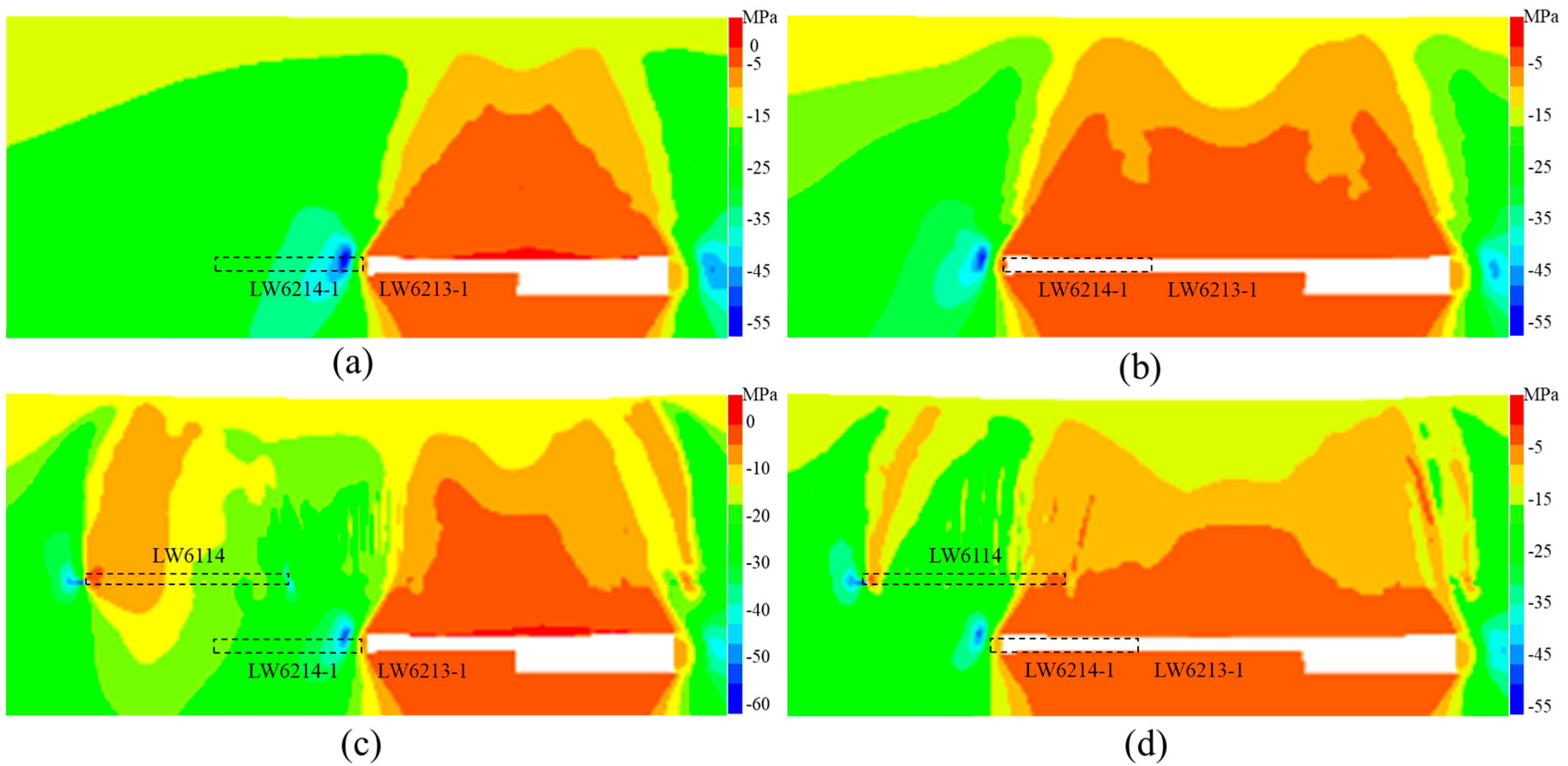
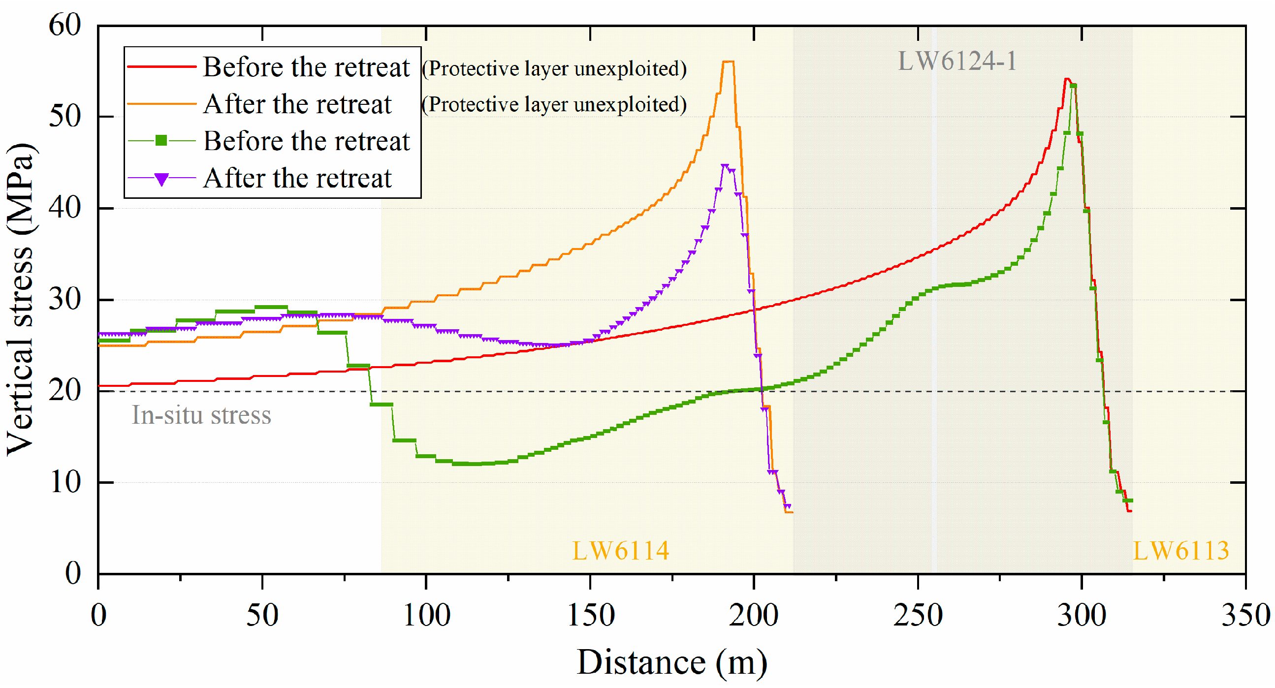
4.2.2. The Effect of Upper Protective Layer Mining

The impact of excavating the UPL on the overlying strata and the stress on the protected layer is investigated, with Figure 8 presenting the evolution of vertical stress in the inclined section on the east side of the longwall panel 6124-1, the location of which is indicated in Figure 7. When the protective layer is not excavated, static load stress concentration occurs in the coal seam on the void side before the 6124-1 working face is mined, and the intake gateroad of the panel also falls within the abutment stress influence zone, as shown in Figure 8a. Due to the relatively large mining height of the coal seam and the smaller width of the goaf on the dip direction, the subsidence of the overlying rock is insufficient. After the retreat of panel 6124-1, the overlying strata of the goaf continue to transfer towards the solid coal side, placing the next successive working face in a high-stress environment, as depicted in Figure 8b. After the excavation of the UPL, a “masonry beam” structure forms above the goaf, bearing the overburden and resulting in lower stress in the coal rock mass beneath the de-stressed region. Most of the area beneath the goaf of the 6114 working face falls within the de-stressed range, and the goaf of panel 6113 has been re-compacted due to the influence of coal seam mining, leading to an increase in the static load stress on the coal seam near the goaf before the longwall panel 6124-1retreat, as shown in Figure 8c. However, most areas of the 6124-1 workface are still in the depressurisation region, especially the intake gateroad, which is under low stress.
The vertical stress on the dip direction of the longwall panel 6124-1, shown in Figure 9, also reflects this characteristic. Before the panel was mined, the peak stresses on the gob-side coal seam of the two mining methods were relatively close to 53 MPa, which was about 18 m from the coal wall. However, as the distance from the return airway increases, the stress in the coal seam beneath the mined protective layer is significantly lower than that of the unmined protective layer, especially near the intake gateroad of the longwall panel. In addition, the unmined area south of panel 6124-1 is in a good region of pressure relief, which is conducive to improving the permeability of the coal seam and promoting gas extraction.

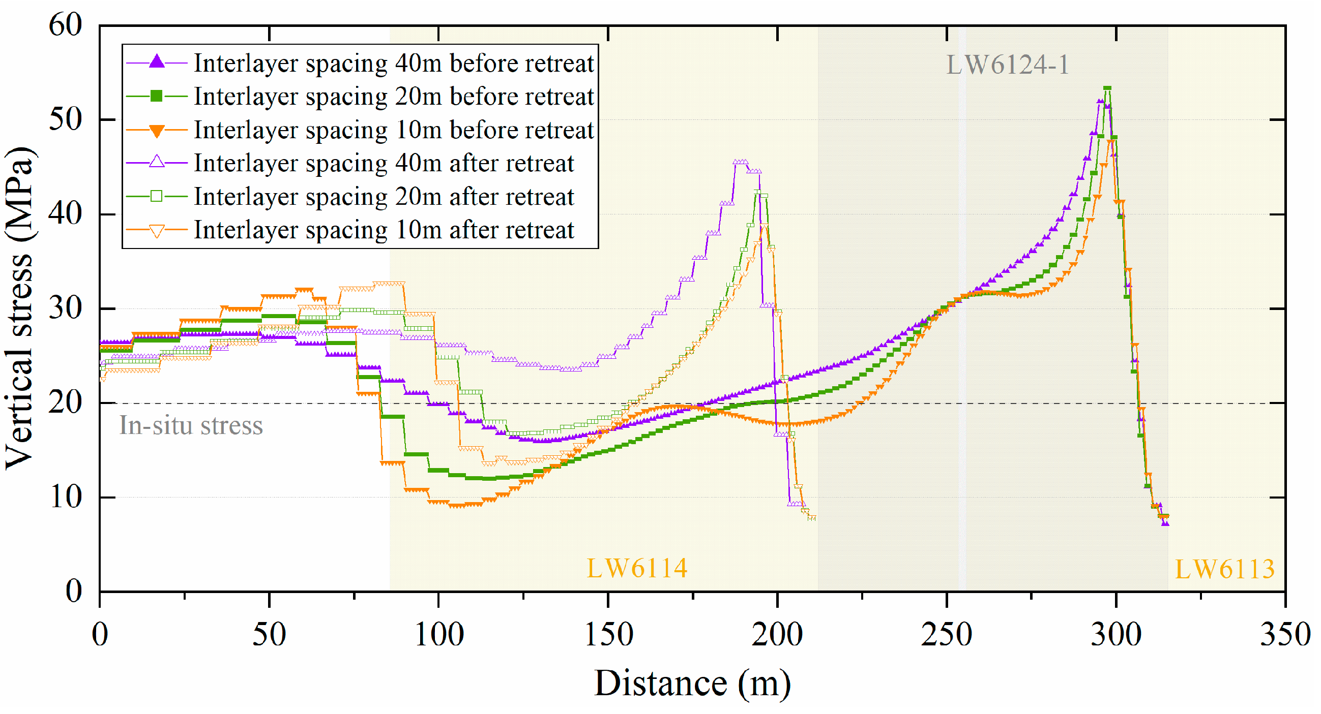
4.2.3. The Effect of Interlayer Spacing

After the extraction of the UPL, its pressure relief region gradually decreases with increasing depth. The interlayer is crucial for the design of the protected layer. In this model, there is only one thick layer of fine sandstone between the protective layer and the protected layer, so the different interlayer spacings are mainly achieved by changing the thickness of this rock stratum. Figure 8c,d and Figure 10 show the stress evolution of the overlying strata in the dip-directional profiles before and after the mining of the longwall panel 6124-1 at interlayer spacings of 40 m, 20 m, and 10 m, respectively. Comparative analysis shows that the smaller the layer spacing, the greater the effective pressure relief range of the UPL and the more obvious the pressure relief effect. In the longwall panel 6124-1, when the layer spacing is 40 m, most of the goaf areas above the working face, including panels 6114 and 6113, have been recompacted, as shown in Figure 8c. Since the area on the goaf-adjacent coal seam of panel 6124-1 is not only the bearing area of the overburden of the No. 2 coal seam but also the recompaction area after the subsidence of the overlying rock of panel 6114, the stress exceeds the in situ stress. At the same time, when there is a thick hard rock layer between the protected layer and the protective layer, the rupture and instability of the rock layer in high-stress areas can easily cause a coal burst. In Figure 10c, the stress on the return gateroad of the 6124-1 working face before mining remains high, but the area near the intake gateroad is in the pressure relief range below the 6114 goaf, with lower stress. In addition, due to the small spacing between layers, it is difficult for the roof rock to accumulate a large amount of elastic energy. Therefore, the failure of the coal mass often manifests as progressive deformation under high stress rather than as sudden catastrophic failure.
Figure 11 shows the vertical stress distribution along the dip direction of the longwall panel 6124-1 at different interlayer spacing. At an interlayer spacing of 10 m, the peak stress on the coal seam near goaf is relatively lower, at 47.74 MPa, and is located 15 m from the coal wall, while at an interlayer spacing of 40 m, the peak stress is 51.91 MPa. When the layer spacing is small, the stress in the protected layer is more significantly influenced by the recompaction stress of the goaf above. For instance, the coal seam stress at a 10 m interlayer spacing shows two peaks below the protective layer, which are not evident in the curve of the coal seam at a 40 m interlayer spacing, which is due to the increase in stress where it is located in the support area of the overburden loads of the UPL of the goaf.

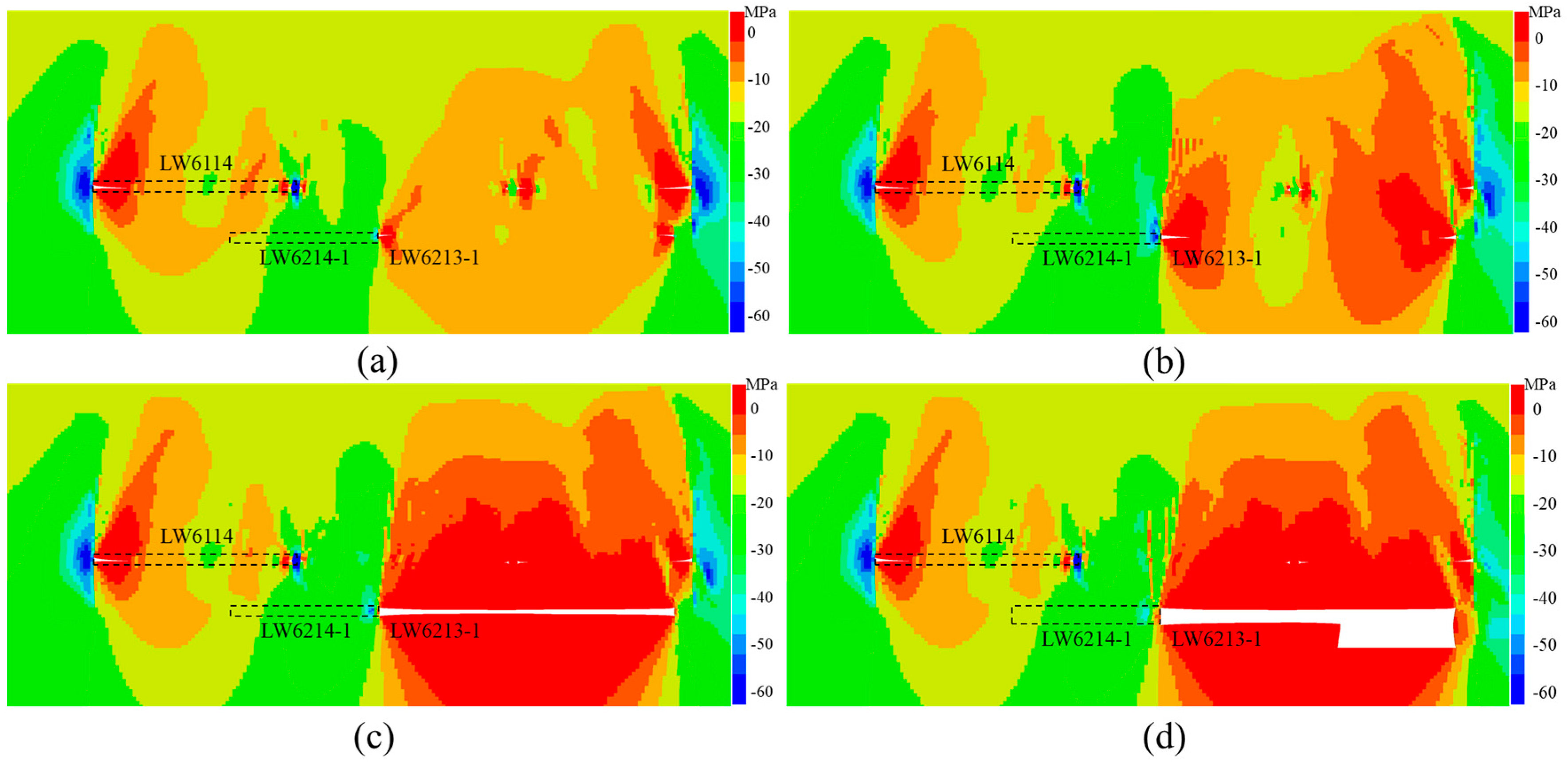
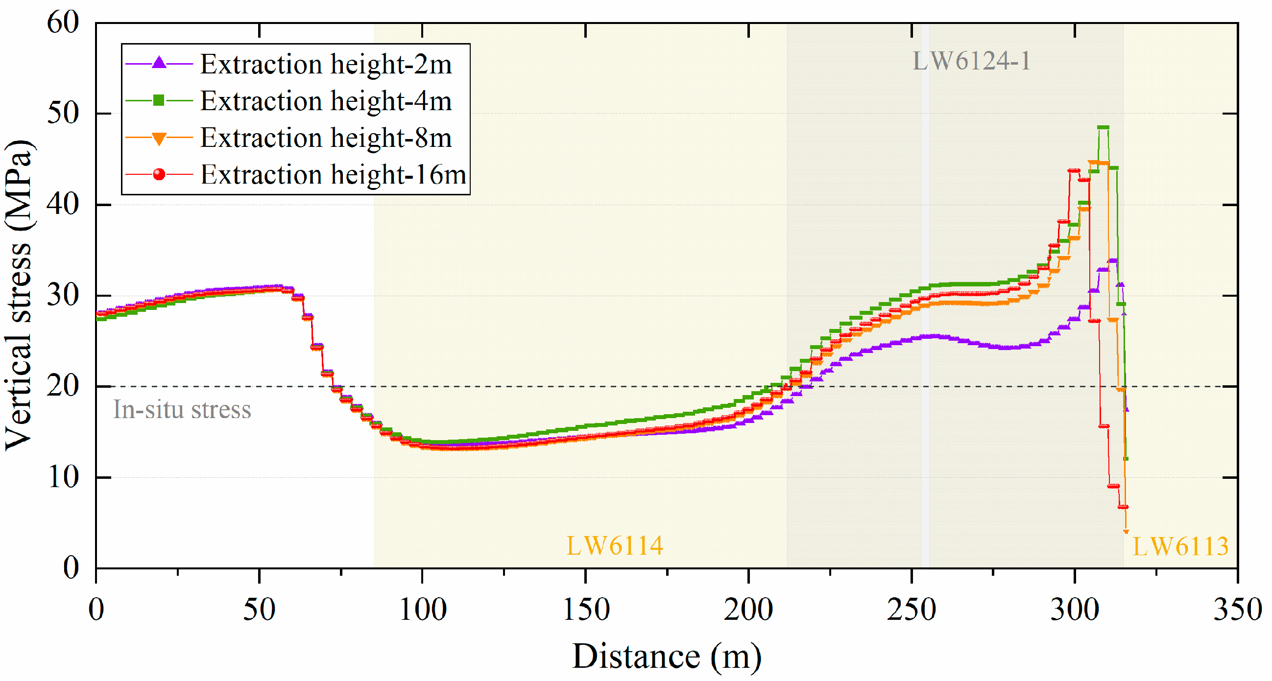
4.2.4. The Effect of Coal Seam Mining Height

The mining height of the coal seam can affect the overburden movement, thereby influencing the depressurisation effect of the protective layer, and the stress evolution in the longwall panel is investigated by excavating coal seams of different thicknesses. By simulating the effect of mining height by excavating different heights of the coal seam each time, the maximum excavation height of the coal seam is 16 m. When the coal seam is mined at a thickness of 2 m, the collapse height of the overlying rock in the goaf is lower, making it easier for the goaf to sink and recompact, thereby having a lesser impact on the longwall panel 6124-1, as shown in Figure 12a. As the mining height of the coal seam increases, the overlying rock in the goaf cannot fully sink, and its load is carried by the coal rock mass on both sides, which will cause further compaction in the goaf of the protective layer and the stress concentration on the coal seam near goaf, as shown in Figure 12c,d. Figure 13 shows the vertical stress distribution along the dip direction of the longwall panel 6124-1 at different extraction heights. When the coal seam is mined at 2 m, the peak stress in the coal seam near goaf is relatively lower, at 33.8 MPa, and is closer to the coal wall, at only 4 m. When the coal seam is mined at 8 m, the peak stress in the coal seam near goaf is 44.63 MPa, located 7 m from the coal wall.
As the mining height of the coal seam increases, the peak vertical stress in the coal seam near the goaf beneath the protective layer gradually increases, and the distance from the coal wall also gradually expands. It is noteworthy that the current simulation results were obtained under the condition of a 40 m thick layer of fine sandstone. The results may vary in different interlayer spacing or other influencing parameters. However, a common conclusion is that higher static stresses may still occur during the mining process beneath the protective layer, especially in relation to the height of coal seam extraction.

5. Engineering Observation and Applications

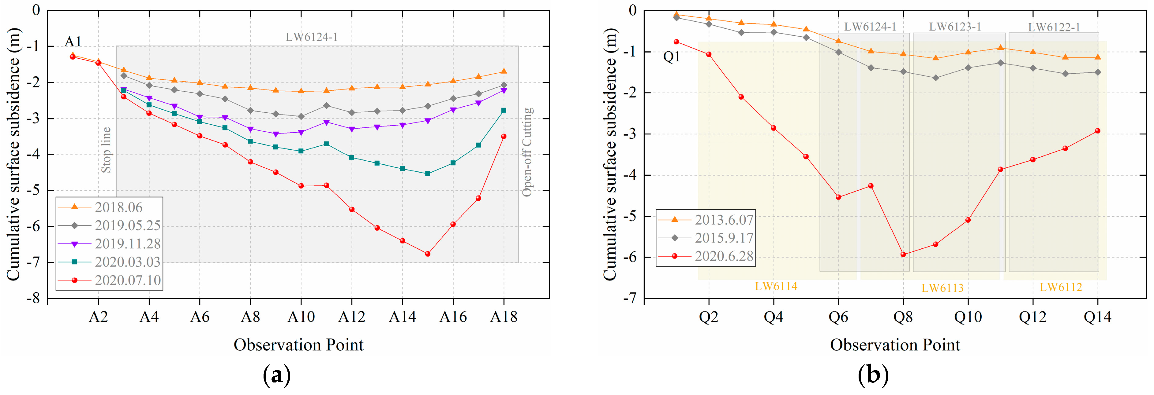
5.1. Surface Subsidence and Overburden Movement

Surface subsidence observation is a primary method for studying the overburden movement in the goaf [46,47]. After coal seam mining, the overlying rock layers collapse under the weight, and when the area of the goaf reaches a certain extent, the overlying rock fractures and develops upwards, causing surface subsidence. The surface subsidence of the Haishiwan coal mine is primarily measured manually. The two surface observation lines above the longwall panel 6124-1 are arranged as shown in Figure 2, one of which is located in the middle of the working face along the strike direction, and the other is located on the eastern side of the working face along the dip direction. Figure 14 shows the observation results for the two sidelines, with the initial observation time being October 2011. The panel 6124-1 began to be mined on 26 July 2018, and completed on 12 October 2019.
Before the longwall panel 6124-1 retreat, a closer observation was made in June 2018, as shown in Figure 14a. The maximum subsidence point in the strike direction was located at point A10 in the middle of the working face, with a cumulative subsidence of 2.25 m, mainly caused by the mining of the oil shale stratum. In the dip direction, a closer observation was made on 17 September 2015, with the maximum subsidence point located at the longwall panel 6123-1 and a cumulative subsidence of 1.63 m. According to the mining conditions, the longwall panel 6123-1 retreating the first level of the No. 2 coal seam has a mining height close to 15 m, while the total mining height of the panels 6122-1 and 6122-2 is close to 30 m. In addition, the mining height of the oil shale layer above the coal seam was 4 m. Therefore, compared to the mining heights of the protective layer and the protected layer, the surface subsidence above the goaf of the coal seam was relatively small. After the retreat of panel 6124-1, according to the observation results on 28 November 2019, the cumulative maximum subsidence in the strike direction was 3.42 m. A closer observation in the dip direction was made on 28 June 2020, with the maximum subsidence point located on the eastern of the longwall panel 6124-1 near the return gateroad, which is caused by further retreat of the panel 6123-2 below the 6123-1 and will not be analysed in detail here. According to the surface observation, the high-position sub-key layer over the goaf did not fracture before the panel 6124-1 retreat, forming an “arch”-shaped overburden structure, which led to stress concentration in the coal seam near the goaf. The results are consistent with the conclusions of the theoretical analysis in Section 3.

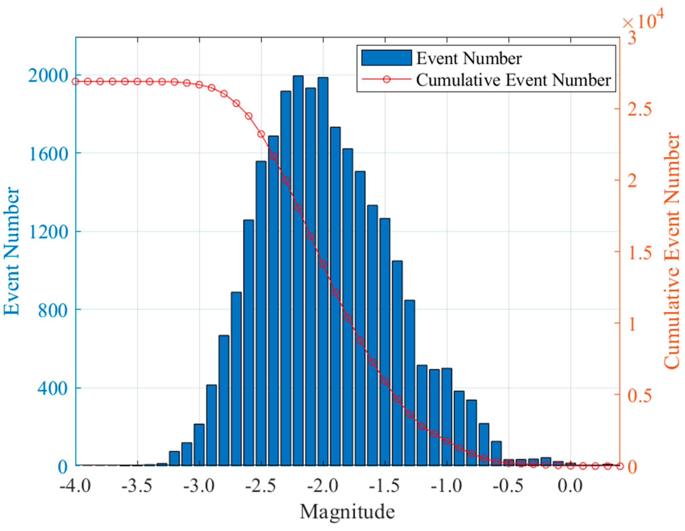
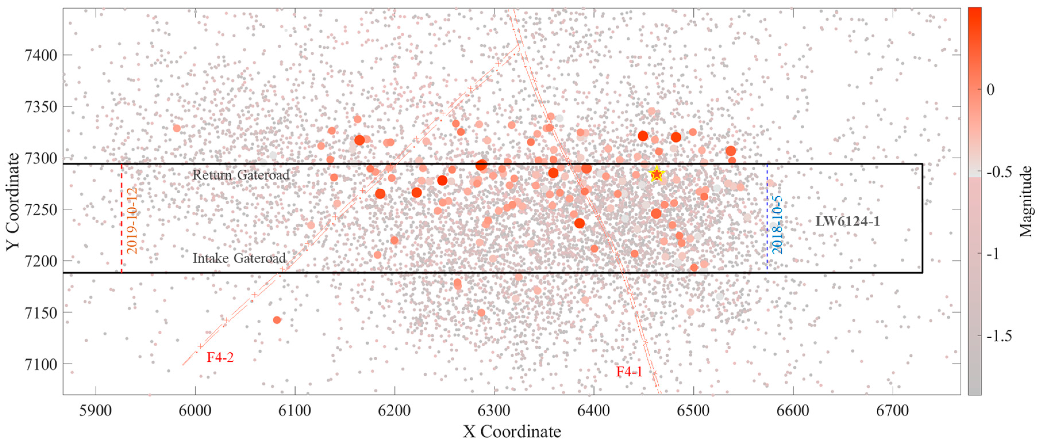
5.2. Mining-Induced Seismicity in Extra-Thick Coal Seam

In the early stage of the longwall panel 6124-1 retreat, mine tremors occurred frequently, with noticeable vibrations in the underground mine. Therefore, the Haishiwan coal mine installed an SOS microseismic monitoring system to collect information on coal and rock fracturing caused by mining activities, and this system officially began operating in early October 2018. A total of 26,883 seismic events were recorded at panel 6124-1 from 5 October to the end of the retreat. The statistical scope is 150 m north of the return gateroad of the longwall panel and 120 m south of the inlet gateroad and the panel. Table 3 shows the statistical characteristics based on the radiated energy of seismic events, with a larger number of events having energy less than 100 J, accounting for 57.09%. According to mining practice, when the energy of a seismic event exceeds 104 J, there is a certain intensity of vibration near the epicentre. When the energy of a seismic event exceeds 105 J, it can cause damage to roadways or excavation spaces. Therefore, even though there were only 13 seismic events with energy greater than 105 J, they pose a significant threat to the safe mining of the coal seam.
In seismology, it is widely accepted to describe the energy released by stratum rupture in terms of Richter magnitude rather than energy. According to statistical studies by Gutenberg and Richter [48], the relationship between Richter magnitude and energy can be expressed by the following formula [49]:
L o g 10 E = 1.5 M L + 4.8
Figure 15 shows the magnitude-frequency distribution of mining-induced seismic events, which is close to a normal distribution. The Richter magnitudes of the seismic events range from −3.59 to 0.49, which is smaller than that observed by Fujin and Ishijima [50]. This phenomenon may be related to the protective layer above the 6124-1 working face having already been mined. In addition, the magnitudes of seismic events in coal mines are significantly smaller than those of natural seismic events, which is related to the rupture scale of rock strata and the depth of the epicentre. However, despite the smaller magnitudes of seismic events, their impact on the underground coal mines should not be underestimated. Mining-induced seismic events, due to their proximity to the mining space, can still cause damage to tunnels and induce strong vibrations in underground spaces, even at small magnitudes.
The distribution of seismic events during the retreat of the longwall panel 6124-1 is shown in Figure 16. The seismic events are not only distributed within the longwall panel but also occur in areas on both the north and south sides of the panel. However, the distribution of large-magnitude seismic events is mainly clustered near the F4-1 and F4-2 faults, especially presenting a nearly linear distribution along the return gateroad. At the same time, small-magnitude seismic events also clustered in the same area, indicating that after the mining of the UPL, the faults still have a significant impact on the stress distribution of the coal seam, especially the coal mass near the goaf. The clustering of seismic events reflects stress concentration areas consistent with the results of the numerical simulation in Section 4.2.1. In addition, the location marked by a pentagram in Figure 16 represents the epicentre of the coal burst that occurred on 5 October 2018, with a magnitude of 0.32, causing significant damage to the return gateroad.

5.3. Prevention and Control Measures

Theoretical analysis, numerical simulation, and surface subsidence observations indicate that there is still a high concentration of stress near the return gateroad of the longwall panel 6124-1, especially around the faults. Due to the thick siltstone layer serving as the immediate roof of the No. 2 coal seam, it can store a substantial amount of elastic energy and cause severe damage to the roadway when it fractures, such as the coal burst that occurred on 5 October. In response to the high static stress encountered during the retreat of the longwall panel 6124-1, it is necessary to conduct destressing measures of the coal seam and deep-hole blasting of the immediate roof separately.
Large-diameter drilling is one of the most effective methods for coal mass destressing, achieved by using drilling machines to bore holes with a diameter of 113 mm into the coal seam and discharging coal dust for pressure relief. The depth of the drill holes is determined based on the distance of the peak stress in the coal seam from the coal wall. For particularly thick coal seams, the hole depth generally needs to reach 20 m, with the arrangement of the drill holes shown in Figure 17. The spacing between holes depends on the stress state of the coal seam, with a denser arrangement in high-stress areas at 1 m intervals and a spacing of 2 m in low-stress areas. Additionally, due to the presence of a thick layer of coal at the bottom of the roadway, coal blasting and large-diameter drilling for destressing are also necessary in high-stress areas.
For the thick immediate roof, the destressing measures mainly include pre-fracturing blasting and roof-cutting blasting, using emulsion explosives for the blasts. The pre-fracturing blast holes are primarily aimed at reducing the integrity of the roof and decreasing the breakage distance of overburden in goaf [51,52]. By arranging a set of blast holes (1#–3#, 4#–6#) on both sides of the longwall face, each set consisting of three blast holes drilled at different angles towards the roof and arranged in a “fan” shape, as shown in Figure 17. The sets of pre-fracturing blast holes are spaced 20 m apart, with a total of seven sets arranged mainly around the F4-1 and F4-2 faults, and the blasting parameters are shown in Table 4. The roof-cutting blast holes are primarily aimed at reducing the hanging length of the thick hard roof, arranged along the entire intake and return gateroads, with two holes in the return gateroad (B1#, B2#) and one in the intake gateroad (B3#). The spacing between each set of blast holes is 8 m, and the blasting parameters are shown in Table 5. According to the retreat situation of the longwall panel, these destressing measures effectively reduced the stress concentration in the coal seam, ensuring mining safety.

6. Discussion

Extra-thick coal seam mining tends to cause stress concentration in the coal seam near the gob side, even under UPL mining conditions. Compared to implementing extensive pressure relief measures, the layout of the longwall panel in the protected layer is a fundamental strategy to avoid stress concentration. Compared to carrying out extensive pressure relief measures, the mining layout of the working face in the protected layer is a strategy to avoid stress concentration from the source. As analysed in Section 4.2, mining of the UPL, interlayer spacing, and the height of coal seam excavation, all influence the stress evolution in the protected layer. Arranging the longwall panel within the effective pressure relief region of the UPL can avoid the necessity for extensive depressurisation measures during mining. In many cases, the relative position between the protective and protected layers is determined by the characteristics of the strata, making it difficult to change the interlayer spacing. For thick coal seams, if the interlayer spacing is large and there is a thick hard roof, reducing the mining height of the first level can lower the static stress on the gob-side coal seam. At the same time, backfilling is also an effective method to control the development height of the collapse zone, thereby reducing the subsidence of the overburden strata and its effect on the gob-side coal seam [53,54,55]. In addition, underground gateroads are the main passages for mining activities, and due to limited support strength, they often face safety risks in high-stress areas. Therefore, a better strategy is to arrange the two roadways of the longwall panel in the pressure relief region of the UPL, which is referred to as the roadway staggered layout [56], as shown in Figure 17. This arrangement avoids placing the return gateroad in the high static stress area, eliminating the need to reduce the height of coal seam excavation.
The roadway staggered arrangement method was first proposed to improve the recovery rate of longwall top-coal caving [57]. Arranging one gateroad of the longwall panel in the goaf after upper layer mining, within a good pressure relief protection range, has gradually been used to avoid high stress in the coal seam near the gob side. It is noteworthy that the offset of the return gateroad and its distance from the upper goaf significantly influence the deformation and stability of the return gateroad. Due to the low strength of the coal, when the distance above the return gateroad is small, the roadway roof is prone to fracturing and may be affected by residual gas and water in the goaf.

7. Conclusions

This paper takes the geological and mining conditions of the Haishiwan mine as the background and studies the stress evolution and influencing factors during the mining of an extra-thick coal seam under a protective layer through theoretical analysis, numerical simulation, and field observation. The main conclusions are as follows:
(1)
The height of coal seam extraction will affect the development of the collapse zone in the goaf and determine the position where the key layer blocks of the overburden form a “masonry beam” structure. The effective support width of the structure at high-position is relatively large, leading to an increased load on the overburden that is supported by the coal rock mass on both sides of the structure. This will result in an increase in stress on the extra-thick coal seam near the goaf and eliminate the pressure relief effect of the protective layer;
(2)
The extraction of the UPL has a significant pressure relief effect, which gradually diminishes with the increase in interlayer spacing, especially when the spacing exceeds 40 m. Faults beneath the protective layer, by altering the continuity of the geological structure, will impact the stress distribution in the coal seam, especially when the interlayer spacing is large. With the increase in coal seam extraction height, the depressurisation effect on the coal seam adjacent to the goaf under the protective layer vanishes, leading to stress concentration;
(3)
The accumulated subsidence on the surface before the retreat of the longwall panel 6124-1 is relatively small, depending on the width of inclination in the goaf and the overburden structure. During the retreat of the panel, mining-induced seismic events clustered around the faults, while large-magnitude seismic events were mainly distributed near the return gateroad, which is associated with the static stress in the coal seam. In response to the high static stress during the retreat of the panel, it is proposed to address the coal seam and roof rock separately with large-diameter drilling and deep-hole blasting.

Author Contributions

Methodology, J.H.; Software, F.L.; Validation, H.H.; Formal analysis, Y.C. and X.M.; Writing—original draft, Y.C.; Supervision, L.D. All authors have read and agreed to the published version of the manuscript.

Funding

This research was funded by the National Key R&D Program of China, grant number 2022YFC3004603, and the National Natural Science Foundation of China, grant numbers 51974302, 51934007 and 52227901.

Data Availability Statement

Data is contained within the article.

Conflicts of Interest

The authors declare that there are no conflicts of interest regarding the publication of this paper.

References

  1. Fuksa, D. Opportunities and Threats for Polish Power Industry and for Polish Coal: A Case Study in Poland. Energies 2021, 14, 6638. [Google Scholar] [CrossRef]
  2. Hancox, P.J.; Götz, A.E. South Africa’s coalfields—A 2014 perspective. Int. J. Coal Geol. 2014, 132, 170–254. [Google Scholar] [CrossRef]
  3. Panaedova, G.; Borodin, A.; Zehir, C.; Laptev, S.; Kulikov, A. Overview of the Russian Coal Market in the Context of Geopolitical and Economic Turbulence: The European Embargo and New Markets. Energies 2023, 16, 6797. [Google Scholar] [CrossRef]
  4. Han, S.; Chen, H.; Long, R.; Cui, X. Peak coal in China: A literature review. Resour. Conserv. Recycl. 2018, 129, 293–306. [Google Scholar] [CrossRef]
  5. Mark, C. Coal bursts that occur during development: A rock mechanics enigma. Int. J. Min. Sci. Technol. 2018, 28, 35–42. [Google Scholar] [CrossRef]
  6. Li, X.; Chai, Y. Determination of pillar width to improve mining safety in a deep burst-prone coal mine. Saf. Sci. 2019, 113, 244–256. [Google Scholar] [CrossRef]
  7. Feng, X.T.; Liu, J.; Chen, B.; Xiao, Y.; Feng, G.; Zhang, F. Monitoring, Warning, and Control of Rockburst in Deep Metal Mines. Engineering 2017, 3, 538–545. [Google Scholar] [CrossRef]
  8. Chai, Y.; Dou, L.; Cai, W.; Małkowski, P.; Li, X.; Gong, S.; Bai, J.; Cao, J. Experimental investigation into damage and failure process of coal-rock composite structures with different roof lithologies under mining-induced stress loading. Int. J. Rock Mech. Min. Sci. 2023, 170, 105479. [Google Scholar] [CrossRef]
  9. Gao, R.; Yu, B.; Xia, H.; Duan, H. Reduction of Stress Acting on a Thick, Deep Coal Seam by Protective-Seam Mining. Energies 2017, 10, 1209. [Google Scholar] [CrossRef]
  10. Wang, H.; Cheng, Y.; Yuan, L. Gas outburst disasters and the mining technology of key protective seam in coal seam group in the Huainan coalfield. Nat. Hazards 2013, 67, 763–782. [Google Scholar] [CrossRef]
  11. Wang, L.; Lu, Z.; Chen, D.-P.; Liu, Q.Q.; Chu, P.; Shu, L.Y.; Ullah, B.; Wen, Z.J. Safe strategy for coal and gas outburst prevention in deep-and-thick coal seams using a soft rock protective layer mining. Saf. Sci. 2020, 129, 104800. [Google Scholar] [CrossRef]
  12. Li, W.; Cheng, Y.P.; Guo, P.-K.; An, F.H.; Chen, M.Y. The evolution of permeability and gas composition during remote protective longwall mining and stress-relief gas drainage: A case study of the underground Haishiwan Coal Mine. Geosci. J. 2014, 18, 427–437. [Google Scholar] [CrossRef]
  13. Kurlenya, M.V.; Seryakov, V.M.; Korotkikh, V.I. Geomechanical substantiation of pillar-and-room sequences of mining the protective layer. Rock Mech. Mine Press. 1991, 27, 269–275. [Google Scholar] [CrossRef]
  14. Korotkikh, V.I.; Tapsiev, A.P.; Red’kin, V.A.; Selyaev, I.S. Improvement of production schemes for constructing protective layers in mining gently sloping deposits. J. Min. Sci. 1990, 26, 277–281. [Google Scholar] [CrossRef]
  15. Yang, W.; Lin, B.Q.; Qu, Y.A.; Zhao, S.; Zhai, C.; Jia, L.L.; Zhao, W.Q. Mechanism of strata deformation under protective seam and its application for relieved methane control. Int. J. Coal Geol. 2011, 85, 300–306. [Google Scholar] [CrossRef]
  16. Zhang, Y. Distribution law of floor stress during mining of the upper protective coal seam. Sci. Prog. 2020, 103. [Google Scholar] [CrossRef]
  17. Yin, W.; Miao, X.; Zhang, J.; Zhong, S. Mechanical analysis of effective pressure relief protection range of upper protective seam mining. Int. J. Min. Sci. Technol. 2017, 27, 537–543. [Google Scholar] [CrossRef]
  18. Zhang, W.; Zhang, D.; Qi, D.; Hu, W.; He, Z.; Zhang, W. Floor failure depth of upper coal seam during close coal seams mining and its novel detection method. Energy Explor. Exploit. 2018, 36, 1265–1278. [Google Scholar] [CrossRef]
  19. Yang, W.; Lin, B.Q.; Qu, Y.A.; Li, Z.W.; Zhai, C.; Jia, L.L.; Zhao, W.Q. Stress evolution with time and space during mining of a coal seam. Int. J. Rock Mech. Min. Sci. 2011, 48, 1145–1152. [Google Scholar] [CrossRef]
  20. Zhang, C.; Yu, L.; Feng, R.; Zhang, Y.; Zhang, G. A Numerical Study of Stress Distribution and Fracture Development above a Protective Coal Seam in Longwall Mining. Processes 2018, 6, 146. [Google Scholar] [CrossRef]
  21. Liu, Z.; Yang, H.; Cheng, W.; Xin, L.; Ni, G. Stress distribution characteristic analysis and control of coal and gas outburst disaster in a pressure-relief boundary area in protective layer mining. Arab. J. Geosci. 2017, 10, 358. [Google Scholar] [CrossRef]
  22. Fang, S.; Zhu, H.; Huo, Y.; Zhang, Y.; Wang, H.; Li, F.; Wang, X. The pressure relief protection effect of different strip widths, dip angles and pillar widths of an underside protective seam. PLoS ONE 2021, 16, e246199. [Google Scholar] [CrossRef]
  23. Cheng, X.; Zhao, G.; Li, Y.; Meng, X.; Tu, Q. Key technologies and engineering practices for soft-rock protective seam mining. Int. J. Min. Sci. Technol. 2020, 30, 889–899. [Google Scholar] [CrossRef]
  24. Feng, Y.; Wang, W.; Zhang, Z.; Yang, W. Pattern of Influence of the Mining Direction of the Protective Seam on the Stress of the Surrounding Rock. Sustainability 2023, 15, 13623. [Google Scholar] [CrossRef]
  25. Jin, K.; Cheng, Y.; Wang, W.; Liu, H.; Liu, Z.; Zhang, H. Evaluation of the remote lower protective seam mining for coal mine gas control: A typical case study from the Zhuxianzhuang Coal Mine, Huaibei Coalfield, China. J. Nat. Gas Sci. Eng. 2016, 33, 44–55. [Google Scholar] [CrossRef]
  26. Cheng, Z.; Pan, H.; Zou, Q.; Li, Z.; Chen, L.; Cao, J.; Zhang, K.; Cui, Y. Gas Flow Characteristics and Optimization of Gas Drainage Borehole Layout in Protective Coal Seam Mining: A Case Study from the Shaqu Coal Mine, Shanxi Province, China. Nat. Resour. Res. 2021, 30, 1481–1493. [Google Scholar] [CrossRef]
  27. Chen, H.; Cheng, Y.; Ren, T.; Zhou, H.; Liu, Q. Permeability distribution characteristics of protected coal seams during unloading of the coal body. Int. J. Rock Mech. Min. Sci. 2014, 71, 105–116. [Google Scholar] [CrossRef]
  28. Yang, M.; Wang, M.; Wang, Y.; Zhang, J.; Zhang, L.; Wang, Z. Coal pore structure changes in upper protective seam after mining: Pingdingshan Shenma Group, Henan Province, China. J. Pet. Sci. Eng. 2022, 218, 111045. [Google Scholar] [CrossRef]
  29. Wang, F.; Zhangm, C.; Liang, N. Gas Permeability Evolution Mechanism and Comprehensive Gas Drainage Technology for Thin Coal Seam Mining. Energies 2017, 10, 1382. [Google Scholar] [CrossRef]
  30. Sun, Q.; Zhang, J.; Zhang, Q.; Yin, W.; Germain, D. A protective seam with nearly whole rock mining technology for controlling coal and gas outburst hazards: A case study. Nat. Hazards 2016, 84, 1793–1806. [Google Scholar] [CrossRef]
  31. Ding, K.; Wang, L.; Wang, W.; Li, Z.; Jiang, C.; Ren, B.; Wang, S. Experimental Study on Gas Seepage Characteristics of Axially Unloaded Coal under Different Confining Pressures and Gas Pressures. Processes 2022, 10, 1055. [Google Scholar] [CrossRef]
  32. Cheng, X.; Zhao, G.; Li, Y.; Meng, X.; Dong, C.; Liu, Z. Researches of fracture evolution induced by soft rock protective seam mining and an omni-directional stereo pressure-relief gas extraction technical system: A case study. Arab. J. Geosci. 2018, 11, 326. [Google Scholar] [CrossRef]
  33. Dou, L.M.; He, X.Q.; Hu, H.E.; Jiang, H.E.; Jun, F.A.N. Spatial structure evolution of overlying strata and inducing mechanism of rockburst in coal mine. Trans. Nonferrous Met. Soc. China 2014, 24, 1255–1261. [Google Scholar] [CrossRef]
  34. Mu, Z.; Dou, L.; He, H.; Fan, J. F-structure model of overlying strata for dynamic disaster prevention in coal mine. Int. J. Min. Sci. Technol. 2013, 23, 513–519. [Google Scholar] [CrossRef]
  35. Cheng, G.; Xu, W.; Shi, B.; Wu, J.; Sun, B.; Zhu, H. Experimental study on the deformation and failure mechanism of overburden rock during coal mining using a comprehensive intelligent sensing method. J. Rock Mech. Geotech. Eng. 2022, 14, 1626–1641. [Google Scholar] [CrossRef]
  36. Ju, J.; Xu, J. Surface stepped subsidence related to top-coal caving longwall mining of extremely thick coal seam under shallow cover. Int. J. Rock Mech. Min. Sci. 2015, 78, 27–35. [Google Scholar] [CrossRef]
  37. Ju, J.; Xu, J. Structural characteristics of key strata and strata behaviour of a fully mechanized longwall face with 7.0 m height chocks. Int. J. Rock Mech. Min. Sci. 2013, 58, 46–54. [Google Scholar] [CrossRef]
  38. Yang, B.; Yuan, S.; Liang, Y.; Liu, J. Investigation of overburden failure characteristics due to combined mining: Case study, Henan Province, China. Environ. Earth Sci. 2021, 80, 143. [Google Scholar] [CrossRef]
  39. Wang, X.; Qin, D.; Zhang, D.; Guan, W.; Xu, M.; Wang, X.; Zhang, C. Evolution Characteristics of Overburden Strata Structure for Ultra-Thick Coal Seam Multi-Layer Mining in Xinjiang East Junggar Basin. Energies 2019, 12, 332. [Google Scholar] [CrossRef]
  40. Jiang, N.; Lv, K.; Gao, Z.; Di, H.; Ma, J.; Pan, T. Study on Characteristics of Overburden Strata Structure Above Abandoned Gob of Shallow Seams—A Case Study. Energies 2022, 15, 9359. [Google Scholar] [CrossRef]
  41. Cai, W.; Dou, L.; Si, G.; Hu, Y. Fault-Induced Coal Burst Mechanism under Mining-Induced Static and Dynamic Stresses. Engineering 2021, 7, 687–700. [Google Scholar] [CrossRef]
  42. Li, Z.; Dou, L.; Cai, W.; Wang, G.; He, J.; Gong, S.; Ding, Y. Investigation and analysis of the rock burst mechanism induced within fault–pillars. Int. J. Rock Mech. Min. Sci. 2014, 70, 192–200. [Google Scholar] [CrossRef]
  43. Cai, W.; Dou, L.; Li, Z.; He, J.; He, H.; Ding, Y. Mechanical Initiation and Propagation Mechanism of a Thrust Fault: A Case Study of the Yima Section of the Xiashi-Yima Thrust (North Side of the Eastern Qinling Orogen, China). Rock Mech. Rock Eng. 2015, 48, 1927–1945. [Google Scholar] [CrossRef]
  44. Piotr, M.; Łukasz, O.; Piotr, B. Modelling the Small Throw Fault Effect on the Stability of a Mining Roadway and Its Verification by In Situ Investigation. Energies 2017, 10, 2082. [Google Scholar] [CrossRef]
  45. Skrzypkowski, K.; Zagórski, K.; Zagórska, A.; Apel, D.B.; Wang, J.; Xu, H.; Guo, L. Choice of the Arch Yielding Support for the Preparatory Roadway Located near the Fault. Energies 2022, 15, 3774. [Google Scholar] [CrossRef]
  46. Cao, J.; Huang, Q.; Guo, L. Subsidence prediction of overburden strata and ground surface in shallow coal seam mining. Sci. Rep. 2021, 11, 18972. [Google Scholar] [CrossRef] [PubMed]
  47. Cui, X.; Wang, J.; Liu, Y. Prediction of progressive surface subsidence above longwall coal mining using a time function. Int. J. Rock Mech. Min. Sci. 2001, 38, 1057–1063. [Google Scholar] [CrossRef]
  48. Gutenberg, B.; Richter, C.F. Magnitude and Energy of Earthquakes. Nature 1955, 176, 795. [Google Scholar] [CrossRef]
  49. Si, G.; Cai, W.; Wang, S.; Li, X. Prediction of Relatively High-Energy Seismic Events Using Spatial–Temporal Parametrisation of Mining-Induced Seismicity. Rock Mech. Rock Eng. 2020, 53, 5111–5132. [Google Scholar] [CrossRef]
  50. Fujii, Y.; Ishijima, Y. Numerical simulation of microseismicity induced by deep longwall coal mining. Min. Sci. Technol. 1991, 12, 265–285. [Google Scholar] [CrossRef]
  51. Kan, J.; Dou, L.; Li, X.; Li, J.; Bai, J.; Cao, J.; Liu, M. Effect of initiation pattern on rock damage and blasting seismic under multi-hole blasting. Geomat. Nat. Hazards Risk 2023, 14, 2192334. [Google Scholar] [CrossRef]
  52. Yang, J.; Fu, Q.; Gao, Y.; Wu, X.; Chang, X.; Li, C. A Novel Method of Combined Deep Hole Blasting for Gob-Side Roadway Protection. Rock Mech. Rock Eng. 2023, 56, 3551–3571. [Google Scholar] [CrossRef]
  53. Skrzypkowski, K. 3D Numerical Modelling of the Application of Cemented Paste Backfill on Displacements around Strip Excavations. Energies 2021, 14, 7750. [Google Scholar] [CrossRef]
  54. Yang, W.; Zhang, W.; Lin, B.; Si, G.; Zhang, J.; Wang, J. Integration of protective mining and underground backfilling for coal and gas outburst control: A case study. Process Saf. Environ. Prot. 2022, 157, 273–283. [Google Scholar] [CrossRef]
  55. Wu, B.; Wang, X.; Bai, J.; Wu, W.; Zhu, X.; Li, G. Study on Crack Evolution Mechanism of Roadside Backfill Body in Gob-Side Entry Retaining Based on UDEC Trigon Model. Rock Mech. Rock Eng. 2019, 52, 3385–3399. [Google Scholar] [CrossRef]
  56. Li, Z.L.; Dou, L.M.; Cai, W.; Wang, G.F.; Ding, Y.L.; Kong, Y. Roadway Stagger Layout for Effective Control of Gob-Side Rock Bursts in the Longwall Mining of a Thick Coal Seam. Rock Mech. Rock Eng. 2016, 49, 621–629. [Google Scholar] [CrossRef]
  57. Jingli, Z.; Qiang, F. New scheme of roadway layout in longwall top-coal caving system. J. China Univ. Min. Technol. 1998, 8, 162–165. [Google Scholar]
Figure 1. Schematic diagram of UPL extraction as a pressure relief measure.
Energies 17 01446 g001
Figure 2. Layout of the longwall panels in mining area I.
Energies 17 01446 g002
Figure 3. Bore histogram in the mining area I.
Energies 17 01446 g003
Figure 4. Motion patterns and force analysis of key blocks.
Energies 17 01446 g004
Figure 5. Schematic diagram of overburden structure for mining extra-thick coal seam under the protection layer.
Energies 17 01446 g005
Figure 6. Numerical model.
Energies 17 01446 g006
Figure 7. The vertical stress in the No. 2 coal seam before the longwall panel 6124-1 mining.
Energies 17 01446 g007
Figure 8. Protective layer extraction and overburden stress evolution: (a) Before 6124-1 retreat without protective layer; (b) after 6124-1 retreat without protective layer; (c) before 6124-1 retreat under protective layer; (d) after 6124-1 retreat under protective layer.
Energies 17 01446 g008
Figure 9. The vertical stress distribution along the dip direction of the longwall panel 6124-1 is influenced by the protective layer.
Energies 17 01446 g009
Figure 10. Interlayer spacing and overburden stress evolution: (a) 20 m interlayer spacing before 6124-1 retreat; (b) 20 m interlayer spacing after 6124-1 retreat; (c) 10 m interlayer spacing before 6124-1 retreat; (d) 10 m interlayer spacing after 6124-1 retreat.
Energies 17 01446 g010
Figure 11. The vertical stress distribution along the dip direction of the longwall panel 6124-1 influenced by interlayer spacing.
Energies 17 01446 g011
Figure 12. Coal seam extraction height and overburden stress evolution: (a) Excavation of 2 m; (b) excavation of 4 m; (c) excavation of 8 m; (d) excavation of 16 m.
Energies 17 01446 g012
Figure 13. The vertical stress distribution along the dip direction of the longwall panel 6124-1 influenced by extraction height.
Energies 17 01446 g013
Figure 14. Observation of surface subsidence at the longwall panel 6124-1. (a) Strike direction; (b) dip direction.
Energies 17 01446 g014
Figure 15. Magnitude–frequency plot for mining-induced seismic events.
Energies 17 01446 g015
Figure 16. Mining-induced seismic events recorded between 5 October 2018 and 24 September 2019.
Energies 17 01446 g016
Figure 17. Pressure relief measures for the extra-thick coal seam mining.
Energies 17 01446 g017
Table 1. The ultimate breakage distance of key strata in Haishiwan coal mine.
Key StrataLithologyThickness (m)Distance from Coal Seam (m)Breakage Distance (m)
Sub-key layer ISiltstone32.2058.28
Sub-key layer IISilty-fine sandstone34.9751.6767.88
Sub-key layer IIISiltstone30.19384.6170.67
Sub-key layer IVFine sandstone34.32416.3077.30
Sub-key layer VFine sandstone31.86552.01105.34
Main key layerFine sandstone61.43602.04256.80
Table 2. Physical and mechanical parameters of the numerical model.
LithologyThickness (m)Density (kg·m−3)Shear Modulus (GPa)Bulk Modulus (GPa)Cohesion (MPa)Friction Angle (°)
Oil shale3021002.7510.421.933
Fine sandstone15280047.07433
Siltstone25245029.392.536
Mud limestone1025702.43.82.535
Oil shale421002.7510.421.933
Siltstone40245029.392.536
No. 2 coal seam3213281.491.672.830
Conglomerate1025502.79.392.536
Gravelly sandstone4527003.212.404.835
Table 3. Statistics on mining-induced seismic events in longwall panel 6124-1.
Energy (J)Number of EventsProportion (%)
<1.0 × 10215,35057.10
1.0 × 10²~1.0 × 103875032.54
1.0 × 10³~1.0 × 10425619.53
1.0 × 10⁴~1.0 × 1022090.78
>1.0 × 105130.05
Table 4. Parameters of blasting holes for roof pre-fracturing.
Blast Hole NumberDip Angle
(°)
Azimuth Angle (°)Diameter
(mm)
Length in Roof Rock (m)Charging Length (m)Charge Density (kg/m)Total Charge (kg)
1601807525223.679.2
2451807525223.679.2
3301807530253.690
44507530253.690
56007525223.679.2
67507525223.679.2
Table 5. Parameters of blasting holes for roof cutting.
Blast Hole NumberDip Angle
(°)
Azimuth Angle (°)Diameter
(mm)
Length in Roof Rock (m)Charging Length (m)Charge Density (kg/m)Total Charge (kg)
B170907525223.679.2
B2701807525223.679.2
B37507525223.679.2
Disclaimer/Publisher’s Note: The statements, opinions and data contained in all publications are solely those of the individual author(s) and contributor(s) and not of MDPI and/or the editor(s). MDPI and/or the editor(s) disclaim responsibility for any injury to people or property resulting from any ideas, methods, instructions or products referred to in the content.

