Article

Addressing Confidence in Modeling of Contrail Formation from E-Fuels in Aviation Using Large Eddy Simulation Parametrization

by
Eduardo Cabrera
1 and
João M. Melo de Sousa
2,*
1
Instituto Superior Técnico, Av. Rovisco Pais, 1049-001 Lisboa, Portugal
2
IDMEC, Instituto Superior Técnico, Universidade de Lisboa, Av. Rovisco Pais, 1049-001 Lisboa, Portugal
*
Author to whom correspondence should be addressed.
Energies 2024, 17(6), 1442; https://doi.org/10.3390/en17061442
Submission received: 6 January 2024 / Revised: 6 March 2024 / Accepted: 14 March 2024 / Published: 17 March 2024
(This article belongs to the Section I1: Fuel)

Abstract

:
As it becomes increasingly necessary to reduce aviation-related emissions, condensation trails present an additional challenge. These are arguably responsible for the largest contribution to radiative forcing in the sector, but the phenomenon is still not as well understood as those involving other agents. The present study employs a large eddy simulation (LES) parametrization to validate a previously developed contrail model in order to assess the feasibility of a multi-model approach to increase confidence in simulations of contrail cirrus formation. Subsequently, the computational model was used to analyze the impact of e-fuels in contrail dynamics, resulting in reductions of over 7% and 14%, respectively, in average contrail lifetime and optical depth, with such improvements increasing if higher blending limits are utilized. This confirmed the potential for e-fuels as the most viable option for near-future large-scale implementations among all sustainable aviation fuel alternatives.

1. Introduction

As with all other transport industries, the aviation sector is faced with the both current and future problem of reducing pollutant emissions in mankind’s struggle to combat climate change. Furthermore, amid the disruptions associated with the COVID-19 pandemic years also came confirmation of the scale of the sector’s carbon footprint, as studies carried out during the most intense lockdown periods showed an immediate reduction in the emissions of greenhouse gases (GHG) and improvement in air quality in areas of otherwise usually high air traffic density [1]. Nevertheless, the steady, albeit slow, return to normality highlighted the need to resume and accelerate efforts in research and development of technologies that may facilitate the transition to carbon-neutral aviation, namely, sustainable aviation fuels (SAF). The latter will play the most important role towards achieving the established near- and medium-term goals, as evidenced by the increasing number of test flights conducted with 100% blends of SAF [2,3].
The most visible and recognizable pollutant emissions associated with the aviation sector are condensation trails (or contrails). Contrails are aircraft-induced cirrus clouds, which may persist and grow to large cirrus cover in ice-supersaturated air. These are triggered from the mixing of the hot and humid engine exhaust gases with ambient cold and dry air. Their optical properties depend not only on the ambient atmospheric conditions but also on both the particles emitted by the aircraft (which, in turn, are determined by the fuel properties and engine control settings) and the particles formed in the aircraft plume [4].
From a physicochemical point of view, contrails originate from the water vapor emitted by aircraft engines that condensates on particle nuclei and subsequently freezes. In order to meet the necessary formation conditions, the ambient air must reach water saturation, and for contrails to persist, the air needs to maintain supersaturation with respect to ice. It is worth pointing out that, due to the fact that the bonds established between molecules in ice are much stronger than the ones in the case of liquid water, there will be a lower flux out of the ice into the vapor space, which means that saturation with respect to ice is achieved with a lower concentration of water molecules than saturation with respect to liquid water. In turn, this means that water saturation will always imply ice supersaturation [5].
In dry air environments, contrails are typically short-lived as lack of sufficient relative humidity levels leads to the evaporation of the ice particles that form in the contrail. In these cases, contrails can disappear only seconds or a few minutes after formation and, therefore, do not achieve extensive lengths. For a contrail to persist, the ambient humidity usually must be larger than the saturation humidity over ice surfaces; relative humidity over ice R H i > 100%. In such conditions, the ice particles within the contrails grow by deposition of water vapor molecules from the ambient air, and the contrails will persist while the ambient air remains in a state of ice-supersaturation. Contrail cirrus, however, can also form and persist in weakly ice-supersaturated air. Aircraft engines release not only water vapor, which promotes water saturation, but also heat, which counteracts the former. Hence, if the water vapor concentration increase due to the emitted water vapor is higher than the total increase in the local liquid water saturation point due to the emitted heat, cirrus cloud formation conditions can be met with only an ice saturation environment instead of typical high ice-supersaturation (of at least 145 to 165%). As a consequence, the latter contrail cirrus clouds can maintain their shape for up to hours, until they evaporate or lose their shape, thus becoming indistinguishable from natural cirrus clouds [6,7].
The impact of contrails and aviation-induced cloudiness on the global climate is still under debate, as this problem only started to be properly addressed in the last decades of the twentieth century, especially following the detection of the ozone hole. Despite having a much shorter lifetime than long-lived GHG, studies have estimated a net radiative forcing (RF) associated with contrail cirrus of 37.5 mW m−2, making it the largest contribution in the aviation sector [7]. There are, however, high uncertainties associated with this estimate, namely, when compared to the uncertainties corresponding to the RF calculations made for major pollutants, such as CO2 and NOx, as portrayed in Figure 1 (only the impact of aerosol-cloud interactions presents a lower confidence level, due to lack of studies and very poor understanding of the processes [8]).
Notably, and despite the fact that the sulfur content in commercial aviation fuel (Jet A/A-1) currently averages 500 ppm worldwide (well below the specifications limit), consensus is still lacking concerning the role of sulfur in the formation of contrails [9,10,11,12,13,14]. However, it must also be noted that a comprehensive review of the properties of individual contrails [10] has reported changes in fuel sulfur content to have minimal impact on contrail onset. Regardless, some of the aforementioned studies have introduced modeling of activation of hydrophobic soot particles, via surface adsorption of sulfur compounds resulting from jet fuel combustion, in order to make those hydrophilic and enable the formation of liquid droplets or ice nuclei. Nevertheless, recent experiments [15] have demonstrated that fuel sulfur up to 700 ppm does not affect soot particle hygroscopicity, thus supporting the view of a weak impact of sulfur compounds on contrail formation.
While plume ice cloud models with various degrees of complexity for mixing and particle microphysics have been developed, most models do not account for the whole contrail life-cycle from contrail formation until dissipation [9]. Furthermore, other more elaborate models, due to their nonlinear nature and strong dependency on meteorological parameters related to contrail formation, suffer from being too computationally demanding, and thus are not suitable for large-scale simulations. The implications of the foregoing scenario may be that the full climatic impact of contrails is still being overlooked. This, nevertheless, also offers an opportunity for the study of effective mitigation measures, due to the fact that any effects would quickly become apparent.
Against this background, the present investigation seeks to expand on the uncertainties associated with most current contrail prediction modeling approaches. Aiming to achieve this goal, the contrail model developed by Narciso and Sousa [16], that was assembled together with the 0-D aircraft engine model proposed earlier by Gaspar and Sousa [17], will be utilized. In previous studies the intermediate calculations in the modeling resulted in larger than initially expected errors, which were attributed to the simplifications and assumptions made due to the high uncertainties and complexity associated with contrail formation, and thus require further validation. In that respect, an LES-based contrail parametrization developed by Unterstrasser [18] was selected to be implemented, and a comparative analysis between its results and those provided by the original modeling for young contrails was conducted with the aim of improving the fidelity of contrail formation predictions. Furthermore, the present research is part of a larger effort to continue the work initiated by Cabrera and Sousa [1], who analyzed in detail the current state of SAF development and production to conclude that synthetic or e-fuels show the most promise to be incorporated in future large-scale implementations. Hence, the aforementioned engine model was also utilized to enable computational simulations regarding the impact of e-fuel usage in different blending ratios.

2. Original Contrail Model

2.1. Contrail Formation

Contrail formation can be explained through the Schmidt–Appleman criterion (SAC), which is used to decide whether an atmosphere is cool and humid enough to allow for the formation of contrails. When the SAC is satisfied, it means that the ambient temperature is below a critical temperature T C , or, alternatively, the ambient relative humidity is above the critical value U C , and the plume mix of exhaust gases and ambient air achieves liquid saturation.
The amount of water vapor has an extreme importance in determining if the SAC is satisfied. The water vapor emission index E I H 2 O can be calculated from Equation (1), where m H is the hydrogen mass ratio in the fuel, and M H 2 O and M H are the molar masses of water and hydrogen, respectively, as follows:
E I H 2 O = m H M H 2 O 2 M H .
From here, with the use of gas and ambient data, such as the individual gas constants of water vapor and air, respectively, R H 2 O and R a i r , the pressure P, and the specific heat of air at constant pressure c p , together with engine outputs, such as the overall propulsion efficiency η , and fuel properties, such as the lower heating value Q, the mixing line gradient G, relating the variation in the water vapor partial pressure with temperature, can be computed following a series of steps that conclude with Equation (2), as given by:
G = R H 2 O R a i r c p E I H 2 O P Q ( 1 η ) .
Using parameter G, the critical temperature can be calculated by solving Equation (3), where e s a t stands for the partial water pressure at saturation, and T M refers to the temperature at the point where the saturation curve and the mixing line meet. The temperature T C is thereby obtained by equating the gradients, as follows:
T C = T M 1 G ( e s a t ( T M ) U a m b e s a t ( T C ) ) .

2.2. Early Stage Contrails

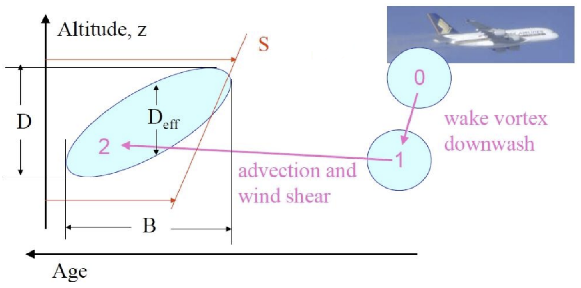
Early stage contrails interact with the engine jet, the aircraft wake vortex, as well as with the ambient turbulence, stratification, and wind shear S. Modeling all these interactions in detail would be difficult due to the physical complexity associated with wake dynamics. Following Schumann [9], the present model estimates the contrail properties at the end of this phase from aircraft and atmospheric parameters instead, as illustrated in Figure 2. The baseline aircraft dimensions were modeled after the BAe 146, as it uses the Lycoming ALF 502 engines that were considered in the development of the 0-D engine model by Gaspar and Sousa [17].
The subsequent modeling is formulated in normalized form, with the characteristic scales based on the initial vortex separation b 0 , and the initial vortex circulation Γ 0 , respectively, obtained from Equations (4) and (5). In the following expressions, s a , M a , and T A S denote the wingspan, the mass, and the true airspeed of the aircraft, respectively, ρ is the air density, and g stands for the gravitational acceleration, as follows:
b 0 = π 4 s a ,
Γ 0 = 4 M a g π s a ρ T A S .
From here, the timescale t 0 is obtained using Equation (6). The initial descent speed ω 0 and the normalized eddy dissipation rate ϵ (from its dimensional value ϵ ) are also calculated using Equations (7) and (8), given by:
t 0 = 2 π b 0 2 Γ 0 ,
ω 0 = Γ 0 2 π b 0 ,
ϵ = ( ϵ b 0 ) 1 3 ω 0 .
For distinction between weak and strong stable stratification, the Brunt-Väisälä frequency is normalized in Equation (9) as N from its dimensional value N B V computed in Equation (10). In Equation (11), θ represents the potential temperature that a parcel of dry air at temperature T E and pressure P E would have if isentropically brought to the reference pressure P r e f = 1000 mbar, as follows:
N = N B V t 0 ,
N B V = g θ d θ d z ,
θ = T E ( P r e f P E ) R a i r / c p .
Depending on the value of N , the maximum descent value of the contrail Δ z w will be calculated according to the brackets defined in Equation (12). At this point, it is now possible to empirically calculate both the contrail depth D, using Equation (13), and the contrail width (or breadth) B, using Equation (14), at the stage where the initial sinking ends (previously defined in Figure 2 as stage 1 and denoted by the latter index in subscript). Based on the foregoing parameters, an effective vertical depth D e f f can also be calculated based on the elliptic (Gaussian) cross-section shape assumed in Figure 2 for the purpose of optical depth computations of aged contrails. In the following equations, m f denotes the mass flow of fuel per flight distance and C D 0 is set to 0.5, but the numerical value of the other empirical constants has already been inserted, as shown below:
Δ z w = 1.49 ω 0 N B V , N 0.8 Δ z w = b 0 ( 7.68 ( 1 4.07 ϵ + 5.67 ϵ 2 ) ( 0.79 N ) + 1.88 ) , N < 0.8 ϵ 0.36
D 1 = C D 0 Δ z w ,
B 1 = 7000 t 0 0.8 m f π 4 ρ D 1 .

2.3. Ice Properties

Contrail ice properties at different stages are defined by the following quantities: the mass mixing ratio of ice I and the total number concentration of contrail ice particles per contrail length N i . When in soot-rich conditions (consistent with present-day emissions from aero-engines), the homogeneous freezing of water-activated soot is the primary ice formation mechanism; therefore, soot emissions dominate ice particle formation [13]. Hence, the initial number of ice particles N f o r m is calculated using Equation (15), as follows:
N f o r m = E I N m f T A S .
For the computation of I, thermal equilibrium between the contrails and the ambient air after contrail formation is assumed, which allows the use of thermodynamic relations. The initial mass mixing ratio of ice I 0 is calculated using Equation (16). This quantity is a function of two ambient properties, namely, the ambient humidity q 0 and the saturation humidity q s a t , which, in turn, depends on the local pressure P 0 and temperature T 0 , as given by:
I 0 = E I H 2 O m f π 4 ρ D 1 B 1 + q 0 q s a t ( P 0 , T 0 ) .
The ice mass variation between stage 0 and stage 1, denoted by Δ I a d , is obtained using Equations (17) and (18), where Δ T a d is the adiabatic temperature variation and the subscript ice stands for the ice saturation, as follows:
Δ I a d = P i c e ( T 0 + Δ T a d ) P 1 P i c e ( T 0 ) P 0 ,
Δ T a d = T 0 R a i r c p P 1 P 0 P 0 .
From the ice mass variation, the number of ice particles per length at stage 1, denoted by N 1 , is provided using the survival factor f s u r v = I 1 I 0 , as in Equation (19) given by:
N 1 = f s u r v N f o r m .

2.4. Contrail Cirrus

After the initial contrail phase, the model enters a loop, thus allowing calculation of the contrail properties along its remaining life-span in order to determine the potential environmental impact. The procedure followed to simulate the life and properties of the contrail cirrus in the original modeling is based on the CoCiP model proposed by Schumann [9], and additional details of the present approach are given by Narciso and Sousa [16].
Briefly, for each calculation point, the contrail trajectory is first updated to account for advection effects using a second-order two-step Runge–Kutta scheme, with the latitude and longitude changing due to the northward and eastward winds, while the vertical trajectory is represented by the ambient pressure variation. For ice crystal particle loss, the present model accounts for sublimation of smaller particles during the turbulent mixing, as well as sedimentation-induced aggregation. Due to this, the contrail is taken as being displaced downward according to the ice particle terminal fall velocity. Contrail dimensions, ice mass, ice particle number, and the optical depth τ are thereby obtained at each trajectory point. The simulation is terminated when the contrail lifetime is assumed to end, which can be defined when there is no more mass content, or when the optical depth reaches a small enough value. In the present case, the calculation loop ends when τ < 10 4 .

3. LES-Based Contrail Parametrization

As mentioned in Section 2, simplifying assumptions were made in the original modeling due to the complexities and high uncertainties associated with contrail formation. In the early stage model, calculations were simplified to account for the lack of suitable models that can accurately simulate the highly complex wake vortex dynamics without incurring a high computational cost. However, this may imply that the uncertainties associated with that calculation phase, while initially accepted as within reasonable margins, could affect the reliability of the results generated by the subsequent contrail cirrus loop, and ultimately lead to undesirable consequences for the validity of the final results.
To assess uncertainties associated with the original contrail model, the parametrization proposed by Unterstrasser [18] was implemented, thus providing an alternative approach for calculation of the early evolution stages of contrails. Since this parametrization is based on LES modeling and, thus, incorporates fine details of the wake vortex dynamics as well as Lagrangian ice microphysics, aiming to explore how vortex processes affect later contrail-cirrus properties [19], a higher confidence level of the corresponding results may be expected. Furthermore, as the parametrization condenses the LES data in a simpler analytical form, its implementation can be performed without severely compromising the run time of the original model, which made its choice suitable for the ensuing validation study. More information about the LES approach can be found in Appendix B.

3.1. Compatibilization of Inputs

As mentioned earlier, the implemented parametrization is based on fully three-dimensional (3D) LES simulations of the contrail vortex phase. These simulations begin at an initial state of seconds after the start of the wake vortex and proceed to obtain the contrail depth and the number of ice particles per length (via computation of the survival factor f s u r v ) for 5 min old contrails. A compatibilization of the inputs with the original model was required first, and these are summarized below.
  • Ambient temperature T, from the atmospheric data model
  • Supersaturation s i , which is related to the ambient relative humidity s i = U a m b 1
  • The dimensional Brunt-Väisälä frequency N B V
  • The ice crystal emission index E I i c e , which, again, is assumed to be equal to the soot emission index for soot-rich regimes
  • The wingspan s a and the mass M a of the aircraft
  • The mass flow of fuel per flight distance m f
The parametrization was first implemented on a large dataset, with certain parameters having a defined range of values that are within the desired simulation conditions. For example, the temperature ranges between 209 and 225 K, while R H i is set between 100 and 140%; both these limits are set so as to represent conditions of high likelihood of contrail formation and persistence. Furthermore, the Brunt-Väisälä frequency ranges between 0.005 and 0.0115 s−1 to model typical upper tropospheric stable conditions, and the ice crystal emission index ranges between 1.4 × 10 13 and 7 × 10 15 kg−1 to allow for both present engine soot emission values as well as the expected future decrease due to technological improvements. Likewise, though it will not be addressed in this paper, other aircraft-dependent parameters can be changed to reflect different types of aircraft. More information about the validity of the parametrization for different sets of values was given by Unterstrasser [18].
Similarly to the simulation model described in Section 2, the characteristic quantities b 0 and Γ 0 , as well as the timescale t 0 and the descent speed ω 0 , can be calculated using Equations (4) through (7).

3.2. Length Scales

Three length scales are introduced to characterize the effects of different phenomena in the evolution of early downward-sinking contrails, namely, z d e s c , which measures the final vertical displacement of the wake vortex, whereas z a t m and z e m i t quantify the impact of supersaturation and water vapor emission in the evolution of ice crystal mass, respectively. Regarding z d e s c , an analytical approximation will be represented by z ^ d e s c . After the circulation Γ 0 has been obtained, z ^ d e s c can be calculated using Equation (20) as follows:
z ^ d e s c = 8 Γ 0 π N B V .
The water vapor emitted from the aircraft engine exhaust increases the water vapor concentration ρ until the plume is supersaturated. Assuming a uniform distribution, the added water vapor concentration ρ e m i t is obtained using Equation (21), given by:
ρ e m i t = ν A p .
In turn, the water vapor emission ν and the plume area A p appearing in Equation (21) are calculated for a plume of radius r p from Equations (22)–(24), as follows:
ν = m ˙ f T A S E I H 2 O ,
r p = 1.5 + 0.314 s a ,
A p = 4 π r p 2 .
Next, the length scales z a t m and z e m i t can be obtained by solving Equations (25) and (26) employing a root-finding bisection method. The dry adiabatic lapse rate Γ d and the gas constant for water vapor R H 2 O are set to 9.8 K km−1 and 461 J kg−1 K−1, respectively, in the aforementioned equations written here as:
( 1 + s i ) e s a t ( T ) T = e s a t ( T + Γ d z a t m ) ( T + Γ d z a t m ) ,
e s a t ( T ) R H 2 O T + ρ e m i t = e s a t ( T + Γ d z e m i t ) R H 2 O ( T + Γ d z e m i t ) .
Finally, the three length scales previously calculated are combined in Equation (27). The parametrization coefficients α a t m and α e m i t are defined by Equations (28) and (29), assuming a reference ice crystal emission index E I i c e , r e f = 2.8 × 10 14 . Whereas α d e s c remains fixed at 0.6, the values of γ a t m and γ e m i t are set depending upon the intended output (see next subsection) from the following expressions:
z Δ = α a t m z a t m + α e m i t z e m i t α d e s c z ^ d e s c ,
α a t m = 1.7 ( E I i c e E I i c e , r e f ) γ a t m ,
α e m i t = 1.15 ( E I i c e E I i c e , r e f ) γ e m i t .

3.3. Ice Crystal Loss

In the determination of the surviving ice crystals, γ a t m and γ e m i t are both set to 0.18 when using Equation (27), aiming to account for the impact of excess moisture in ice crystal loss. The approximated survival factor f ^ s u r v is then obtained from Equations (30) and (31), with β 0 = 0.45 , β 1 = 1.19 and α 0 = 1.35 , as follows:
f ^ s u r v = a ^ ( z Δ ) ,
a ^ ( x ) = β 0 + β 1 π arctan ( α 0 + x 100 ) .
Once the survival factor has been determined, the number of ice crystals in the young contrails of age t = 5 min can be obtained again from Equations (15) and (19), as previously expressed for the original modeling.

3.4. Contrail Depth and Width

In contradistinction, as the contrail depth depends mostly on the impact of the wake vortex, and only slightly on crystal loss, the quantities z Δ and f ^ H are computed with γ a t m and γ e m i t set to 0; here, it must be noted that f ^ H is calculated in the same manner as f ^ s u r v using Equation (30).
The parametrized contrail depth H ^ can be obtained through Equations (32) and (33), with η 1 = 6 , η 2 = 0.15 and x s = 0.2 , given by:
H ^ = z ^ d e s c × b ^ ( f ^ H ) ,
b ^ ( x ) = η 1 x , x [ 0 , x s ] η 2 x + ( η 1 η 2 ) x s , x [ x s , 1 ] .
The LES parametrization does not enable a direct computation of the contrail width. In fact, this parameter will not be as relevant as the contrail depth or the ice crystal number for the remainder of the contrail evolution. Nevertheless, an estimation of the horizontal spreading rate of a contrail can be obtained from the simple expression given by Equation (34), which is based on the evaluation of transverse profiles of the ice crystal mass after the vortex phase, as follows:
W ˙ = H ^ × S .
It is noteworthy that for typical values of the parametrized contrail depth H ^ = 400 m and vertical wind shear S = 0.005 s−1 (Cf. Figure 2), the parametrized contrail width W ^ increases at a rate of 1/8 km min−1, which, in practice, means that any errors eventually introduced by the initial width estimation would become less relevant in contrail-to-cirrus evolutions of several hours.
When the values of parameters N ^ s u r v (knowing the parametrized survival factor f ^ s u r v ), H ^ , and W ^ have been calculated, the mean ice crystal number concentration n m e a n can be estimated from Equation (35), provided that it is assumed that the ice crystals are spread over a rectangular cross section, as follows:
n ^ m e a n = N ^ s u r v H ^ W ^ .

3.5. Implementation, Verification, and Validation

Aiming at a validation of the computational implementation of the parametrization modeling, Figure 3 shows a comparison between the simulated and parametrized survival factors. The selected simulation values were extracted from data available in reference [18], and were obtained from a series of 3D LES simulations of the contrail vortex phase with the use of an EULAG-LCM model system developed at the German Aerospace Center (DLR).
These simulations [19,20] study different conditions, with variations in temperature, relative humidity, ice crystal emission index, and fuel flow, in order to assess how these quantities impact contrail formation for an aircraft of the type of a Boeing 777. Additional data from similar simulations made for other aircraft types are also available in reference [18]. Altogether, these simulations indicate that the contrail depth depends most strongly on the supersaturation level and aircraft wingspan, and to a lesser extent on the temperature and the Brunt-Väisälä frequency, whilst the survival factor is mainly dependent on the supersaturation and ice crystal emission. As the supersaturation level and, consequently, the relative humidity, affects both the contrail depth and the survival factor, differences in its value for the different cases have been emphasized using a color system in Figure 3. The results show an average relative error of 12.4% for the cases analyzed, which implies a good level of confidence in the approximations.
A similar analysis for the contrail depth is presented in Figure 4, in which the average relative error was approximately 9.6%, which can be deemed acceptable, as even a difference of 20 to 30 m will not have a major impact in subsequent contrail evolution calculations. As the contrail depth is affected by the wingspan of the aircraft, most values for the cases shown in Figure 4 are within the 350 to 450 m range. Moreover, the calculated parametrized values show differences of less than 1% with respect to counterparts published by Unterstrasser [18], which proved that the computational implementation of the LES parametrization was successfully verified.

4. Simulation Results

4.1. Impact of E-Fuels

The computational tool based on the 0-D aircraft engine model mentioned in Section 2.2 requires a specific set of fuel properties to perform the subsequent operations. Hence, these properties need to be obtained from the existing literature or other available sources. As biofuel research and development have been carried out for decades, such properties are available through a selection of different sources.
Concerning e-fuels, since their development is considerably behind that of biofuels, and only more recently have efforts been made to accelerate it [1], detailed fuel properties are not readily available, as the existing literature is mainly focused on proof-of-concept demonstrations. Nevertheless, since for the case of power-to-liquids (PtL) synthesized using the Fischer–Tropsch (FT) pathway the only difference in regard to other alternative fuels utilizing the FT-SPK process lies in the methods used for syngas production, one may, therefore, assume that the fuel properties remain relatively similar, and any conclusions regarding engine performance and contrail formation also apply. As such, the available data from FT fuels will be utilized in the present study, and the results will be averaged for comparison purposes.
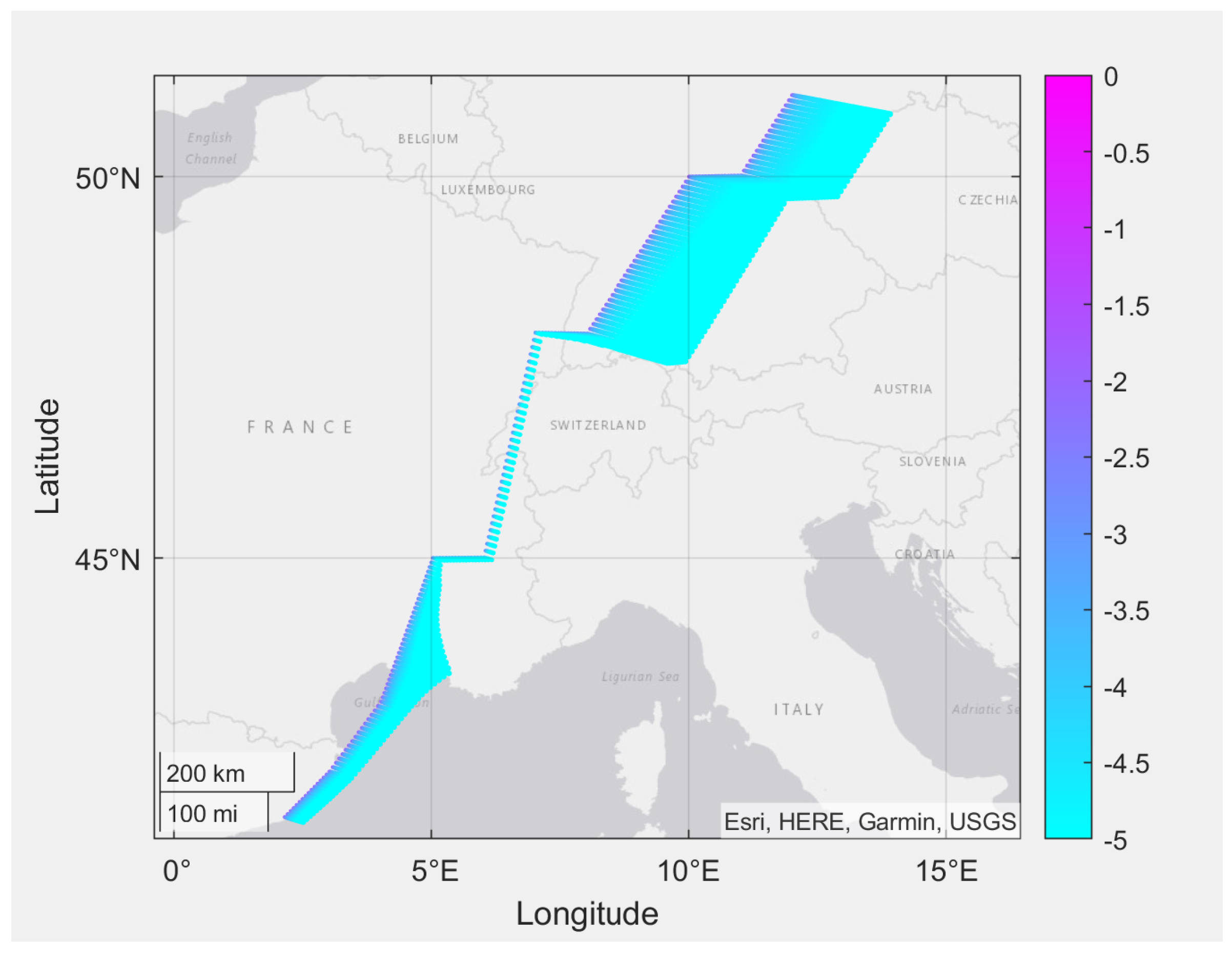
The relevant fuels and respective fuel properties available in the database of the computational tool are presented in Table A1 of Appendix A. In addition, routes from the built-in database were selected so that not only the effect of different ambient conditions could be analyzed, but also so that these would accurately represent real flight routes routinely employed in air transport. For example, the results of optical depth at contrail trajectory points can be visualized using the computational tool with integrated contrail modeling, as illustrated in Figure 5 for one of the specified routes used to generate the bulk of the data presented and discussed in this section.
In contrail formation-propitious environments, the impact of FT e-fuels on contrail lifetime and optical depth results was analyzed. Cloud optical depth studies are of paramount importance to assess cloud-radiation interactions, since the optical depth is key for determining shortwave cloud reflectance and absorption, longwave emissivities, and adiabatic heating rates [21]. As portrayed in Figure 6, the use of the mandatory 50% blending limit resulted in an average decrease of approximately 7.6% in contrail lifetime and 14.6% in optical depth for the studied cases. Impact on lifetime is less felt in contrails with short lifetimes, increasing in long-lasting contrail cirrus scenarios, as expected. For comparison, simulations were also carried for HEFA biofuels, as these currently have the highest TRL [1], and are currently subjected to a similar blending limit of 50%. Two fuels from different feedstocks (mixed fats and camelina) were analyzed, with fuels from camelina feedstocks (HEFA-C) showing a larger positive impact in both lifetime and optical depth reduction (7.4 and 14.5%, respectively) than those from mixed fats feedstocks (6.1 and 12.0%).
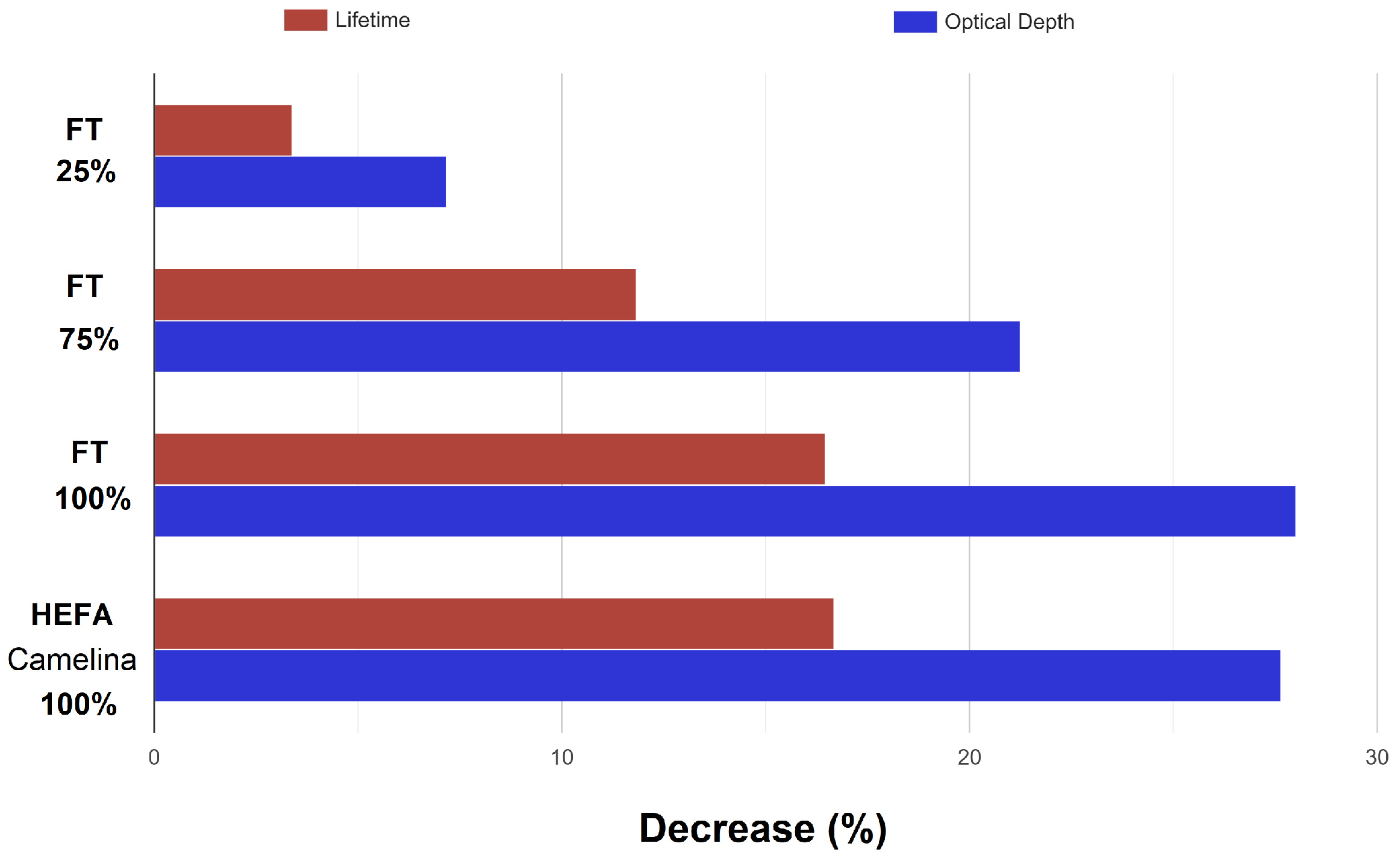
Since one of the near- to medium-term goals for the alternative fuel industry is to achieve higher values of maximum allowed blending limits, eventually reaching 100% conventional fuel substitution, the effect of different blends should also be analyzed. As shown in Figure 7, a higher volume of SAF naturally yields larger environmental gains regarding both the lifetime and optical depth of contrails, as might be anticipated. For FT fuels, 100% blends show an improvement of 8.9% in shortening the contrail lifetime, and 13.4% in optical depth reduction, with respect to conventional fuel values when compared to those for the 50% maximum limit. On the other hand, differences with respect to the use of HEFA fuel from camelina feedstock in a complete drop-in scenario remain small (less than 0.5% for both lifetime and optical depth), similarly to the case for 50% blends. However, one should not straightforwardly conclude that the usage of both these types of fuels can be deemed identical in terms of environmental benefits. It must be noted that the total environmental impact associated with all other pre-usage stages cannot be discarded, as explored in the review by Cabrera and Sousa [1].
Irrespective of the present results, the current blending limits for different SAF pathways are determined based on compatibility with current engine requirements and, despite continuous improvements, not all pathways exhibit the same potential to eventually become 100% blend-certified. A possible solution to maximize SAF usage and circumvent the necessity of conventional fuel blending is to blend multiple alternative fuels in a way that the resulting fuel properties meet all specified requirements for 100% usage since, conceivably, as many blending components as needed could be used to replicate the properties of Jet A/A-1 [22]. However, as more research needs to be conducted regarding the compatibility between different SAFs, this option was not analyzed here.

4.2. Shortcomings of the Original Contrail Model

As previously explained, the original contrail model [16] estimates the early age properties at a stage 1 defined by the wake vortex timescale t 0 . As the LES-based parametrization described in detail in Section 3 provides results for young contrails aged 5 min, the contrail cirrus calculation loop in the original modeling (corresponding to the process of stages 1 → 2 in Figure 2) must be interrupted to ensure physical compatibility between these distinct approaches. Hence, in order to carry out an in-depth analysis of the shortcomings of the original contrail model in the framework of the LES-based parametrization, a time break-loop condition was added at t > 5 min.
Although the inputs for both approaches are obtained from the atmospheric model and the aircraft engine model, the initial state of the LES-based parametrization is defined as occurring after the start of the wake vortex, that is, t 0 > 0 , as depicted in Figure 8. Despite this discrepancy amounting to only a few seconds in wake vortex formation, with most of the quantities therefore experiencing only negligible variations, others are greatly affected, namely, the relative humidity. If contrail formation has already started, then the SAC was satisfied, and so there is a state of supersaturation of the air with respect to ice in the plume mix. Therefore, to accommodate for these differences, the ice relative humidity R H i was added as a user input in this analysis so that its effect on the results may be duly accounted for.
A comparison between the survival factor f s u r v values produced by the original contrail modeling and the LES-based parametrization for young contrails was performed for a selection of flight route points, as the physical definition of this parameter coincides in both cases. In contrast, the contrail depth values cannot be adequately related between these approaches because of the fundamental differences established in the definition of the latter parameter. Namely, the definition adopted by the LES-based parametrization (Cf. Section 3) incorporates effects related to ice crystal loss via the length scales z a t m and z e m i t . The original contrail model (Cf. Section 2), on the other hand, follows a more simplified viewpoint that does not take into account these effects, thus precluding any relevant conclusions regarding the confidence level in the original modeling from a direct comparison of the contrail depths. However, as noted before in Section 3.5, moderate variations in the contrail depth do not lead to major differences in subsequent contrail evolution calculations.
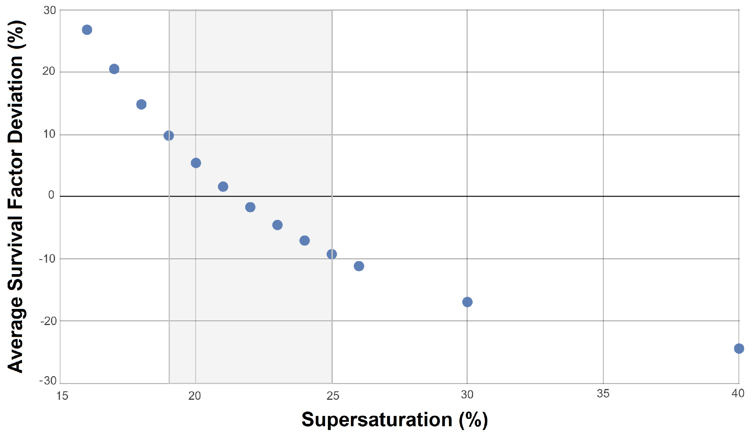
In the present analysis, the best ice survival factor accordance between the two approaches, corresponding to average deviations of the order of ± 10 % , is found for supersaturation values ranging from 18 to 25%, as shown in Figure 9. For high (up to 40%) supersaturation and close to saturation (<10%) scenarios, the deviation between survival factor values increases significantly. Nevertheless, since the routes considered in this analysis mostly represent heavy-traffic flight paths and as such are chosen so as to avoid extreme atmospheric conditions, typical contrail properties should emerge. Hence, moderate levels of supersaturation, say around 20%, are still those most likely to be encountered at mid-latitude routes [23].

5. Conclusions

As the fight against climate change intensifies, the aviation industry must accelerate efforts to mitigate its consequences on the Earth’s climate. Such efforts include investing in fundamental research to allow a better understanding of the impact of different pollutants. The detrimental impact of contrails is undeniable, and yet, despite its major contribution to the sector’s RF, the phenomena regarding contrail formation and persistence are still not adequately understood. This lacuna in knowledge affects confidence in research conducted with the objective of accurately assessing the impact of climate mitigation measures. To that extent, the use of an LES-based parametrization enables the quantification and reduction of uncertainties in standard contrail models. Specifically, the coupling of a larger-scale model with an LES-based parametrization accounting for processes strongly affecting the contrail evolution during the vortex phase significantly increases the confidence level of the overall computational predictions.
Moreover, the simulations carried out in this work regarding the use of e-fuels successfully demonstrated their potential in mitigating contrail-related adverse effects. Both the contrail lifetime and optical depth showed significant decreases for the regulated blending limits. Additional simulations also enabled it to be concluded that should maximum blending limits be adjusted or even lifted in the future, the mitigation effects will be substantially larger, thus leading to even greater environmental gains.

Author Contributions

Conceptualization, E.C. and J.M.M.d.S.; methodology, E.C.; investigation, E.C.; resources, E.C. and J.M.M.d.S.; writing—original draft preparation, E.C.; writing—review and editing, E.C. and J.M.M.d.S.; supervision, J.M.M.d.S.; project administration, J.M.M.d.S.; funding acquisition, J.M.M.d.S. All authors have read and agreed to the published version of the manuscript.

Funding

This work was supported by national funding through FCT—Fundação para a Ciência e a Tecnologia, I.P., in the framework of project UIDB/50022/2020.

Data Availability Statement

The original contributions presented in the study are included in the article, further inquiries can be directed to the corresponding author.

Conflicts of Interest

The authors declare no conflicts of interest.

Abbreviations

The following abbreviations are used in this manuscript:
CoCiPContrail Cirrus Prediction Model
CTLCoal-to-Liquid
FTFischer–Tropsch
GHGGreenhouse Gases
GTLGas-to-Liquid
HEFAHydroprocessed Esters and Fatty Acids
LESLarge Eddy Simulation
PtLPower-to-Liquid
RFRadiative Forcing
SACSchmidt–-Appleman Criterion
SAFSustainable Aviation Fuel
SPKSynthetic Paraffinic Kerosene
TASTrue Air Speed
TRLTechnological Readiness Level
Nomenclature
η Propulsion efficiency
ϵ Eddy dissipation rate (J/(kg s))
Γ 0 Initial vortex circulation (m2/s)
Γ d Dry adiabatic lapse rate (K/km)
ν Water vapor emission (kg/m)
ρ Density (kg/m3)
ρ e m i t Emitted “concentration” (kg/m3)
τ Optical depth
θ Non-dimensional total temperature
AArea (m2)
BContrail width (m)
b 0 Initial vortex separation (m)
c p Specific heat of air at constant pressure (J/(kg K))
DContrail depth (m)
e s a t Partial water pressure at saturation (Pa)
E I H 2 O Water emission index (kg-water/kg-fuel)
E I i c e Ice crystal emission index (kg-fuel−1)
E I N Particle number emission index (kg-fuel−1)
f s u r v Fraction of surviving ice crystals
GMixing line gradient (Pa/k)
gGravitational acceleration (m/s2)
H ^ Parametrized depth for a 5 min old contrail (m)
IIce mass ratio
m f Mass flow of fuel per flight distance (kg/(s m))
m H Hydrogen mass ratio in the fuel
M a Aircraft mass (kg)
M H Molar mass of hydrogen (kg/mol)
M H 2 O Molar mass of water (kg/mol)
NNumber of ice crystals per flight distance (m−1)
N Normalized Brunt-Väisälä frequency
N B V Brunt-Väisälä frequency (s−1)
n ^ m e a n Parametrized mean ice crystal number concentration (m−3)
PPressure (Pa)
QFuel combustion heat (J/kg)
qAbsolute humidity (kg/kg)
R a i r Gas constant for air (J/(kg K))
R H 2 O Gas constant for water vapor (J/(kg K))
rRadius (m)
R H i                   Ambient relative humidity with respect to ice
S                  Vertical wind shear (s−1)
s a                   Wing span of aircraft (m)
s i                   Ambient supersaturation
T                  Temperature (K)
t                  Time (s)
U                  Ambient relative humidity
W ˙                   Estimated horizontal spreading rate of the contrail (m/s)
W ^                   Parametrized width for a 5 min old contrail (m)
w 0                   Initial descent speed of wake vortex (m/s)
z                  Altitude (m)
z Δ                   Balance length scale (m)
z a t m                   Supersaturation length scale (m)
z d e s c                   Vortex length scale (m)
z e m i t                   Emission length scale (m)

Appendix A. Fuel Properties

Table A1. Required fuel properties from the computational model’s database.
PropertiesSymbolJet A-1GTLCTLHEFA R-8HEFA C
Net Heat of Combustion, MJ/kgQ43.244.24444.144.3
Density at 15 °C, kg/m ρ 15 802737762763751
Viscosity at −20 °C, kg/mv3.912.63.65.53.3
Surface Tension at 25 °C, mm2/s σ 27.423.825.225.824.8
Initial Boiling Point,  °C T b , i 151146149156151
10% Recovered,  °C T 10 % 169162166178161
50% Recovered,  °C T 50 % 199169180218182
90% Recovered,  °C T 90 % 243184208263237
Final Boiling Point,  °C T b , f 262198228274259
Hydrogen Content, % weight H % 13.8715.615.115.315.4
Hydrogen to Carbon Molar Ratio h / c 1.9192.2032.1192.1532.169
Molecular Weight, kg/kmolM160.5146156177160
Critical Temperature, QC T c 392.3346.5364.5394.2367.1
Critical Pressure, bar P c 21.8820.9521.2717.819.79
Smoke Point, mm % S P 2340404050

Appendix B. LES Approach

The 3-D LES simulations of the contrail vortex phase were performed using the EULAG-LCM model system developed at DLR. The EULAG base model is utilized to solve the momentum and energy equations by employing the Multidimensional Positive Definite Advection Transport Algorithm (MPDATA). The EULAG-LCM model is then completed by coupling EULAG to a microphysics module with Lagrangian ice particle tracking [19]. The new explicit aerosol and ice microphysics model allows for a complete definition and accurate simulations of the ice microphysical processes related to cirrus formation.
Following flow field initialization, turbulent fields are created in runs for a defined stratification and eddy dissipation rate, and then superimposed with a counter-rotating vortex pair. For the wake vortex simulations, a variant of a nonlinear predictor scheme is employed in order to minimize the computational burden.
The LES approach leading to the simulations that are the basis for the parametrization used in this work involves lengthy formulations, which are beyond the scope of the present study. Hence, for more specific details regarding the LES simulations, the reader is referred to Unterstrasser [19], and Sölch and Kärcher [24].

References

  1. Cabrera, E.; Sousa, J.M.M. Use of Sustainable Fuels in Aviation—A Review. Energies 2022, 15, 2440. [Google Scholar] [CrossRef]
  2. AIN. GE Honda Aero Continues Neat SAF Tests. Available online: https://www.ainonline.com/aviation-news/business-aviation/2023-10-20/ge-honda-aero-continues-neat-saf-tests (accessed on 15 November 2023).
  3. AIN. Gulfstream Completes First Transatlantic Flight on 100% SAF. Available online: https://www.ainonline.com/aviation-news/business-aviation/2023-11-20/gulfstream-completes-first-transatlantic-flight-100-saf (accessed on 27 November 2023).
  4. Schumann, U. On conditions for contrail formation from aircraft exhausts. Meteorol. Z. 1996, 5, 4–23. [Google Scholar] [CrossRef]
  5. Gierens, K.; Spichtinger, P.; Schumann, U. Ice Supersaturation. In Atmospheric Physics: Background–Methods–Trends; Springer: Berlin/Heidelberg, Germany, 2012; pp. 135–150. [Google Scholar]
  6. Schumann, U. Formation, properties and climatic effects of contrails. Comptes Rendus Phys. 2005, 6, 549–565. [Google Scholar] [CrossRef]
  7. Burkhardt, U.; Kärcher, B. Global radiative forcing from contrail cirrus. Nat. Clim. Chang. 2011, 1, 54–58. [Google Scholar] [CrossRef]
  8. Lee, D.S.; Fahey, D.W.; Skowron, A.; Allen, M.R.; Burkhardt, U.; Chen, Q.; Doherty, S.J.; Freeman, S.; Forster, P.M.; Fuglestvedt, J.; et al. The contribution of global aviation to anthropogenic climate forcing for 2000 to 2018. Atmos. Environ. 2021, 244, 117834. [Google Scholar] [CrossRef] [PubMed]
  9. Schumann, U. A contrail cirrus prediction model. Geosci. Model Dev. 2012, 5, 543–580. [Google Scholar] [CrossRef]
  10. Schumann, U.; Baumann, R.; Baumgardner, D.; Bedka, S.T.; Duda, D.P.; Freudenthaler, V.; Gayet, J.-F.; Heymsfield, A.J.; Minnis, P.; Quante, M.; et al. Properties of individual contrails: A compilation of observations and some comparisons. Atmos. Chem. Phys. 2017, 17, 403–438. [Google Scholar] [CrossRef]
  11. Wong, H.-W.; Yelvington, P.E.; Timko, M.T.; Onasch, T.B.; Miake-Lye, R.C.; Zhang, J.; Waitz, I.A. Microphysical Modeling of Ground-Level Aircraft-Emitted Aerosol Formation: Roles of Sulfur-Containing Species. J. Propuls. Power 2008, 24, 590–602. [Google Scholar] [CrossRef]
  12. Paoli, R.; Shariff, K. Contrail Modeling and Simulation. Annu. Rev. Fluid Mech. 2016, 48, 393–427. [Google Scholar] [CrossRef]
  13. Kärcher, B.; Yu, F. Role of aircraft soot emissions in contrail formation. Geophys. Res. Lett. 2009, 36, 1–5. [Google Scholar] [CrossRef]
  14. Kärcher, B. Formation and radiative forcing of contrail cirrus. Nat. Commun. 2018, 9, 1824. [Google Scholar] [CrossRef] [PubMed]
  15. Grimonprez, S.; Wu, J.; Faccinetto, A.; Gosselin, S.; Riber, E.; Cuenot, B.; Cazaunau, M.; Pangui, E.; Formenti, P.; Doussin, J.-F.; et al. Hydrophilic properties of soot particles exposed to OH radicals: A possible new mechanism involved in the contrail formation. Proc. Combust. Inst. 2021, 38, 6441–6450. [Google Scholar] [CrossRef]
  16. Narciso, M.; Sousa, J.M.M. Influence of Sustainable Aviation Fuels on the Formation of Contrails and Their Properties. Energies 2021, 14, 5557. [Google Scholar] [CrossRef]
  17. Gaspar, R.M.P.; Sousa, J.M.M. Impact of alternative fuels on the operational and environmental performance of a small turbofan engine. Energy Convers. Manag. 2016, 130, 81–90. [Google Scholar] [CrossRef]
  18. Unterstrasser, S. Properties of young contrails—A parametrisation based on large-eddy simulations. Atmos. Chem. Phys. 2016, 16, 2059–2082. [Google Scholar] [CrossRef]
  19. Unterstrasser, S. Large-eddy simulation study of contrail microphysics and geometry during the vortex phase and consequences on contrail-to-cirrus transition. J. Geophys. Res. Atmos. 2014, 119, 7537–7555. [Google Scholar] [CrossRef]
  20. Unterstrasser, S.; Görsch, N. Aircraft-type dependency of contrail evolution. J. Geophys. Res. Atmos. 2014, 119, 14015–14027. [Google Scholar]
  21. Kärcher, B.; Burkhardt, U.; Unterstrasser, S.; Minnis, P. Factors controlling contrail cirrus optical depth. Atmos. Chem. Phys. 2009, 9, 6229–6254. [Google Scholar] [CrossRef]
  22. Kramer, S.; Andac, G.; Heyne, J.; Ellsworth, J.; Herzig, P.; Lewis, K. Perspectives on Fully Synthesized Sustainable Aviation Fuels: Direction and Opportunities. Front. Energy Res. 2022, 9, 782823. [Google Scholar] [CrossRef]
  23. Dekoutsidis, G.; Groß, S.; Wirth, M.; Krämer, M.; Rolf, C. Characteristics of supersaturation in mid-latitude cirrus clouds and their adjacent cloud-free air. Atmos. Chem. Phys. Discuss. 2023, 23, 3103–3117. [Google Scholar] [CrossRef]
  24. Sölch, I.; Kärcher, B. A large-eddy model for cirrus clouds with explicit aerosol and ice microphysics and Lagrangian ice particle tracking. Q. J. R. Meteorol. Soc. 2010, 136, 2074–2093. [Google Scholar] [CrossRef]
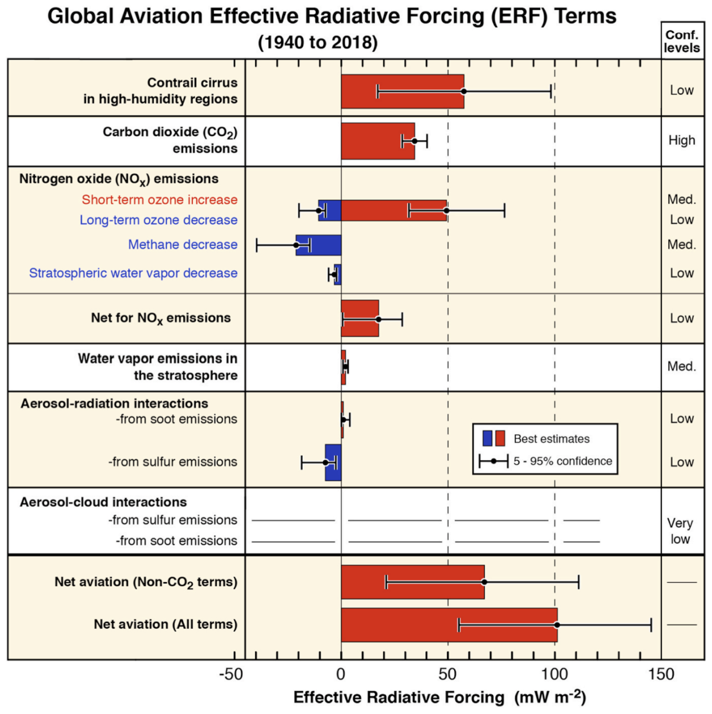
Figure 1. Best-estimates for climate forcing terms from global aviation from 1940 to 2018. Confidence levels were defined based on available evidence and agreement. Adapted from Lee et al. [8].
Energies 17 01442 g001
Figure 2. Schematic of contrail size and dynamics with respect to altitude and age, subjected to wind shear S. Stage 0 represents the contrail at the time of formation, t = 0 ; stage 1 represents the contrail after sinking due to the wake vortex downwash at t = t 0 ; stage 2 represents the cross-section of an aged contrail. Adapted from Schumann [9].
Energies 17 01442 g002
Figure 3. Comparison between simulated and parametrized survival factors. Red symbols represent simulations for saturated conditions, green for 10% supersaturation, black for 20%, purple for 30%, and blue for 40%.
Energies 17 01442 g003
Figure 4. Comparison between simulated and parametrized contrail depths. Red dots represent simulations for saturated conditions, green for 10% supersaturation, black for 20%, purple for 30% and blue for 40%.
Energies 17 01442 g004
Figure 5. Contrail formation plotted over a typical flight route considered in the analysis of the impact of e-fuels. Colour contours represent the logarithm of the optical depth τ at trajectory points, revealing contrail cirrus for τ > 10 4 .
Energies 17 01442 g005
Figure 6. Impact of FT and HEFA fuels in contrail lifetime (red) and optical depth (blue), with respect to simulations for 100% conventional jet fuel, for the maximum blending limits currently allowed.
Energies 17 01442 g006
Figure 7. Impact of different blends of FT and HEFA-C fuels in contrail lifetime (red) and optical depth (blue), with respect to simulations for 100% conventional jet fuel.
Energies 17 01442 g007
Figure 8. Schematic representation of the process of ice crystal loss between the initial and final stages of the LES-based parametrization, where N f o r m is the number of ice particles at stage 0, and N s u r v stands for the number of surviving ice crystals at stage 1. The initial state of the original contrail model corresponds to the beginning of the jet phase, where N s o o t is the number of emitted soot particles from the engine. Adapted from Unterstrasser [18], where AC type denotes the aircraft type.
Energies 17 01442 g008
Figure 9. Average deviation of survival factor f s u r v values from the LES-based parametrization with respect to those in the original contrail model for a range of user-input supersaturation initial states.
Energies 17 01442 g009
Disclaimer/Publisher’s Note: The statements, opinions and data contained in all publications are solely those of the individual author(s) and contributor(s) and not of MDPI and/or the editor(s). MDPI and/or the editor(s) disclaim responsibility for any injury to people or property resulting from any ideas, methods, instructions or products referred to in the content.