Article

Nine-Switch Multiport Converter Applied to Battery-Powered Tramway with Reduced Leakage Current

by
Antonio D. D. Almeida
1,*,
Fabrício Bradaschia
1,
Cassiano Rech
2,
Carolina A. Caldeira
1,
Rafael C. Neto
1 and
Gustavo M. S. Azevedo
1
1
GEPAE Research Group, Department of Electrical Engineering, Federal University of Pernambuco, Recife 50670-901, Brazil
2
GEPOC Research Group, Department of Electrical Engineering, Federal University of Santa Maria, Santa Maria 97105-900, Brazil
*
Author to whom correspondence should be addressed.
Energies 2024, 17(6), 1434; https://doi.org/10.3390/en17061434
Submission received: 6 February 2024 / Revised: 11 March 2024 / Accepted: 14 March 2024 / Published: 16 March 2024
(This article belongs to the Special Issue Advanced Electric Powertrain Technologies for Electric Vehicles)

Abstract

:
Electrically powered rail transport is constantly increasing in order to meet the high demand for people and cargo transportation, whether with high-speed trains, subways, suburban trains, or electric tramways. In these types of applications, power electronics solutions such as integrated and efficient converters with multiple functionalities are highly desirable. Among these converters, one family stands out for its ability to generating multiple output terminals with reduced number of switches, namely, the nine-switch converter. Therefore, this paper proposes a multiport converter solution based on the nine-switch converter topology that integrates multiple functionalities with a reduced switch count. The converter, responsible for the power drive of the electric tramway, is exclusively powered by a battery. Moreover, it presents a strategically connected passive filter that provides a low-impedance path for high-frequency currents, avoiding leakage of the current circulation in the induction motor. Its phase-shift pulse-width modulation is capable of reducing the high-frequency components of the current delivered by the battery. The energy storage system is designed to optimize the system capacity based on the known real load profile of a public tramway, with a maximum power of 532.1 kW. The control system is designed and applied considering the battery as the energy source. Simulations were performed in the Matlab/Simulink environment to validate the proposed system, along with experiments using a reduced-scale prototype controlled by the dSPACE platform. The results present the converter’s proper operation with integration of the source and AC load, presenting improved features compared with conventional solutions in terms of reduced leakage of the current circulation from the AC load and reduced battery current ripple.

1. Introduction

In today’s society, public mobility plays a crucial role in the pursuit of sustainable transportation. With regard to their propulsion systems, electric motors offer several advantages over internal combustion engines, including higher energy conversion efficiency, no emission of polluting gases, lower noise emissions, and decreased complexity, cost and maintenance frequency [1,2]. Due to these and other advantages, urban transport systems with electric motors, such as buses, trains, and tramways, are key players in reducing traffic congestion and promoting sustainable infrastructure in densely populated urban areas [3].
However, despite the benefits of electric mobility, the power supply systems for these electric vehicles have a significant impact on infrastructure and in the appearance of urban centers. When considering electric trains, the impacts become even greater due to the exposure of high-voltage overhead wires, which pose risks of electrical shocks and electromagnetic fields that are harmful to the human body [4]. In the context of electric trains, these vehicles can be characterized by their power supply systems, which can be based on alternating current (AC) or direct current (DC), each with its own characteristics and peculiarities. Examples of these two alternatives can be found in a number of previous works [5,6,7]. In 2018, Ref. [5] pointed out that there were more than 200,000 km of electrified railways. Of this total, approximately 100,000 km uses DC railway electrification, which is more common in urban centers (subways and tramways) because power can be easily injected into the catenary (overhead wire). On the other hand, high-power technologies are more common in AC railway electrification, as the high required voltages are unsuitable for urban networks [6,7].
The power dynamics of electric trains pose another challenge, as they consume energy during acceleration while in motion and draw power from substations without a fixed electric connection. However, under braking the electric motor becomes a generator, converting the kinetic energy applied to the rotor into electrical energy through regenerative braking. To address this need, offboard energy storage systems (ESSs) can be introduced and installed at fixed locations [8], as illustrated in Figure 1a. These devices allow for the use of regenerated energy without modifying substations.
Furthermore, the implementation of onboard ESSs, as shown in Figure 1b, has led to enhanced system efficiency. By integrating these ESSs directly into electric trains, energy can be used within the vehicle itself, thereby eliminating losses associated with transmission and irregular power flows that could result in voltage fluctuations along the catenary [9,10,11]. This advancement makes the electric traction system more flexible and reliable and enables catenary-free operation. In such scenarios, ESSs can be recharged at stations, while the converter draws power from the substation via the pantograph, a device located on the top of the vehicle for connecting to the catenary and receiving electrical energy [12]. Nonetheless, the use of onboard ESSs brings about challenges related to their suitable design for electric tramways while optimizing volume and ensuring catenary-free operation [13,14].
Although an ESS can be used to store energy to make electric tramways catenary-free, the motors of electric tramways need their energy to be processed properly. For this purpose, power converters are applied to connect the power supply and the load, as these typically have different characteristics. Figure 2 illustrates a conventional system schematic highlighting the need for power converters to connect the ESS and the load. Examples of electric tramway power systems can be found in [15,16]. In [15], a hybrid system was proposed for an electric tramway powered by a fuel cell and batteries; however, further explanations of both the modulation strategies and converter design were not provided. In [16], various converter configurations for this application were presented with the aim of integrating ESSs into an electric tramway motor drive, including proposals featuring reduced numbers of components. Nevertheless, in all presented variations the number of components remained notably high, with one configuration reaching a maximum of eighteen switches with transformers and another including a minimum of ten switches. Such complexity can compromise the integration between load and ESS. Among conventional topologies found in the literature, which present issues associated with the number of components, the neutral point clamped (NPC) [17], flying capacitor [18], and back-to-back converter [19,20] approaches stand out, with the latter being the solution shown in Figure 2.
As an alternative to traditional converters, several studies have explored more modern topologies. For instance, a quasi-Z converter was proposed in [21] to enhance performance and speed in battery control and management for off-road vehicles; however, the high number of magnetic components could result in reduced system efficiency. Another interesting converter for connecting a DC source to an AC load is the split-source inverter (SSI) presented in [22]. In this converter, diodes are used to connect a DC source to the midpoint of the legs of a voltage source inverter (VSI). Nonetheless, this converter exhibits a unidirectional characteristic, making it suitable for photovoltaic applications but impractical for electric vehicles, which require bidirectional current flow.
The nine-switch inverter (NSI) is a very appealing alternative to the back-to-back converter for three-phase power electronics applications. This is primarily thanks to its reduced number of switches, allowing for a compact system design. This converter is mainly used in applications where traditional AC-DC-AC converters, such as back-to-back converters, are required. Example use cases for the NSI converter can be found in [23,24,25,26,27,28,29,30,31]. Despite its widespread usage in various power electronics applications, the application of NSI converters to battery-powered electric vehicles has not been addressed in the literature.
In addition to the need for efficient converters to ensure reliable operation, it is imperative to monitor and preserve the motors to prevent premature wear. Such wear occurs due to current leakage during motor operation, which can damage the motor windings and lead to wear on the bearings. Therefore, research efforts have focused on employing passive filters [32,33], different topologies, and active filters [34,35,36] as well as various modulation strategies [37,38,39] with the aim of reducing or eliminating current leakage. However, there is a lack of studies addressing current leakage reduction and battery operation in converters.
Based on the above discussion, this paper introduces an NSI multiport converter applied to a battery-powered tramway with a focus on reducing current leakage. The proposed approach aims to enhance the efficiency and reliability of the tramway’s power system while attenuating the detrimental effects of current leakage. This paper presents the following contributions:
  • Application of a multiport NSI converter in an electric tramway system for connecting the DC source to the AC load, resulting in a more compact solution compared to conventional topologies.
  • Development of a single control scheme for regulating the battery current and voltage, enabling battery energy management. As a consequence, this eliminates the need for additional control schemes to cover regenerative braking and substation charging.
  • Specification of the main characteristics of the ESS and the DC link capacitance based on the energy variation in components for real load conditions.
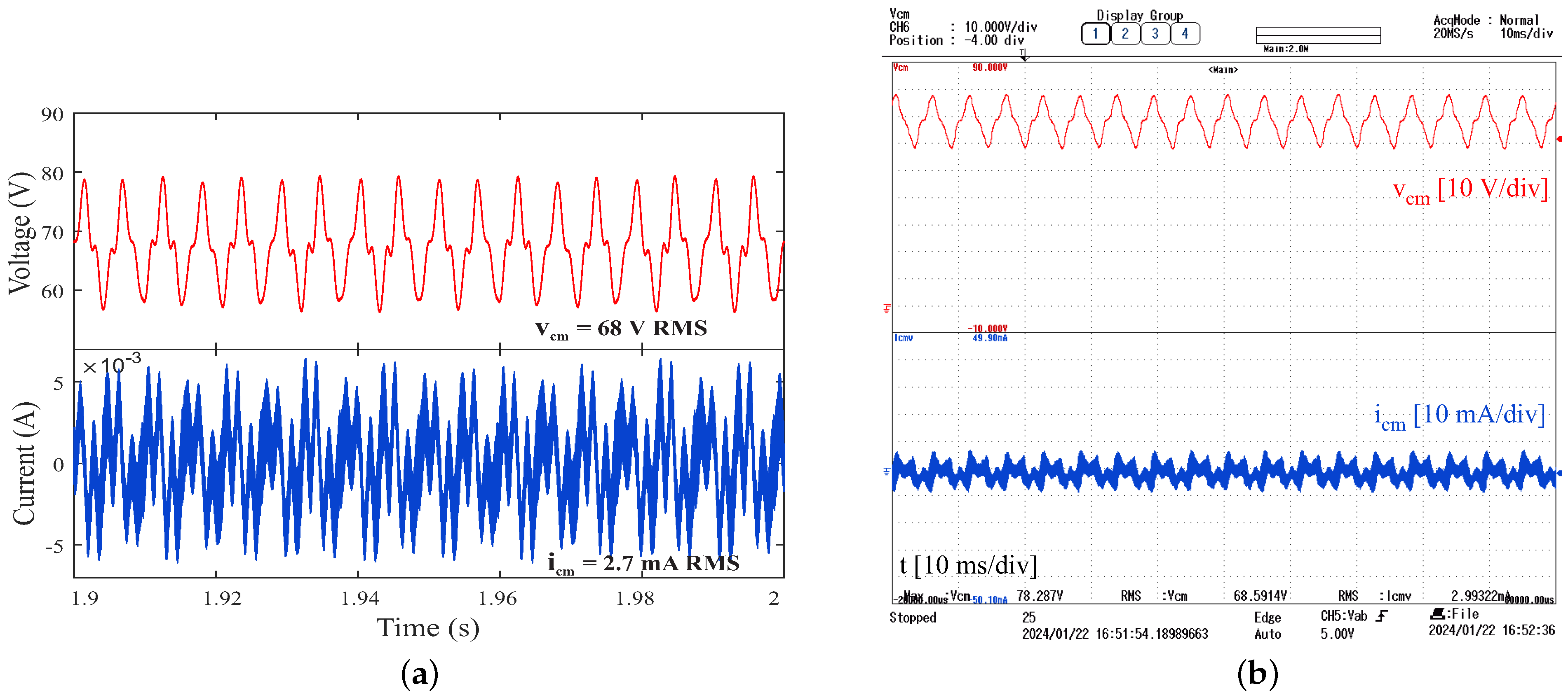
  • Reduction of current leakage in the load through the use of passive filters, preventing premature wear on the motor windings and bearings.
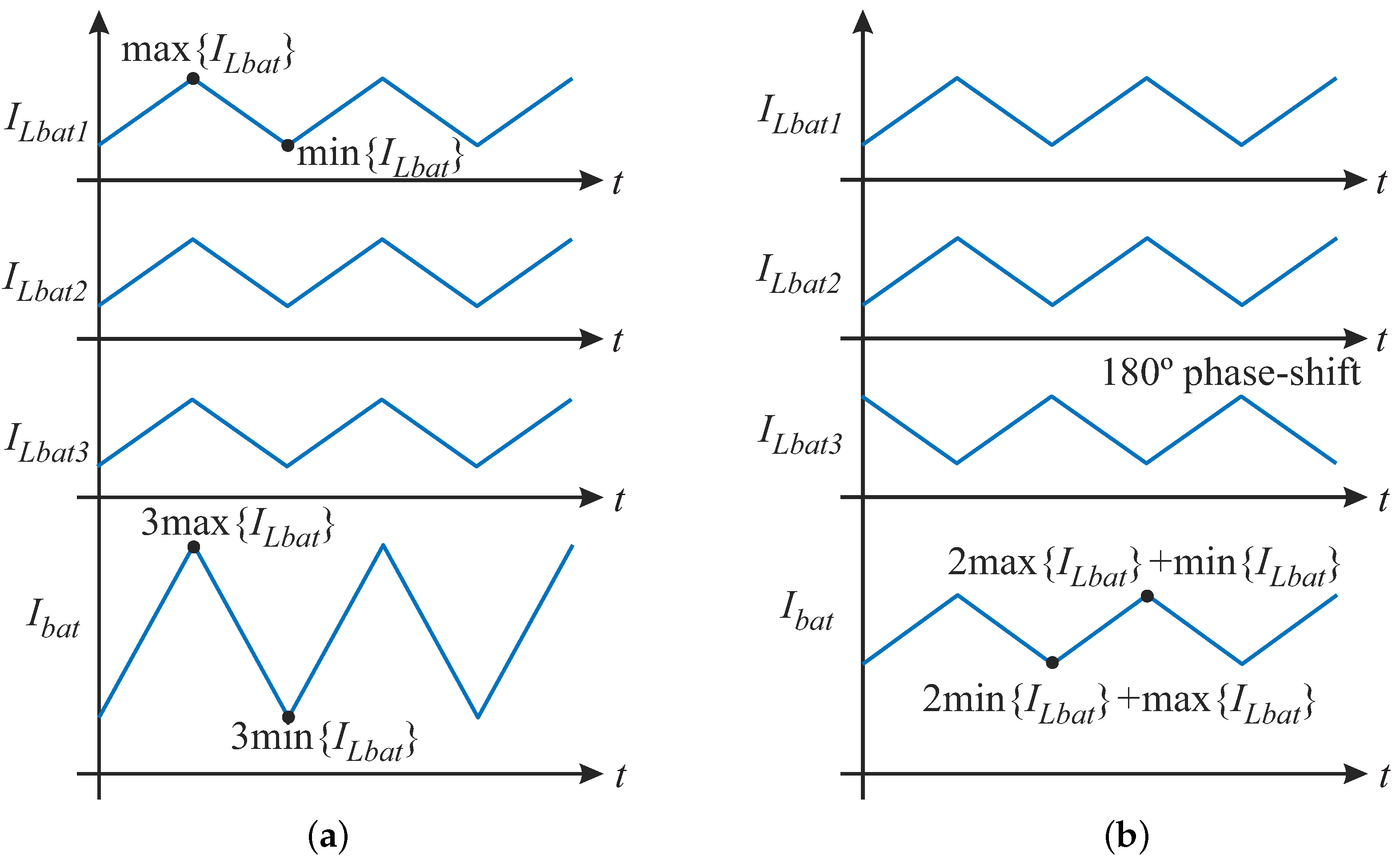
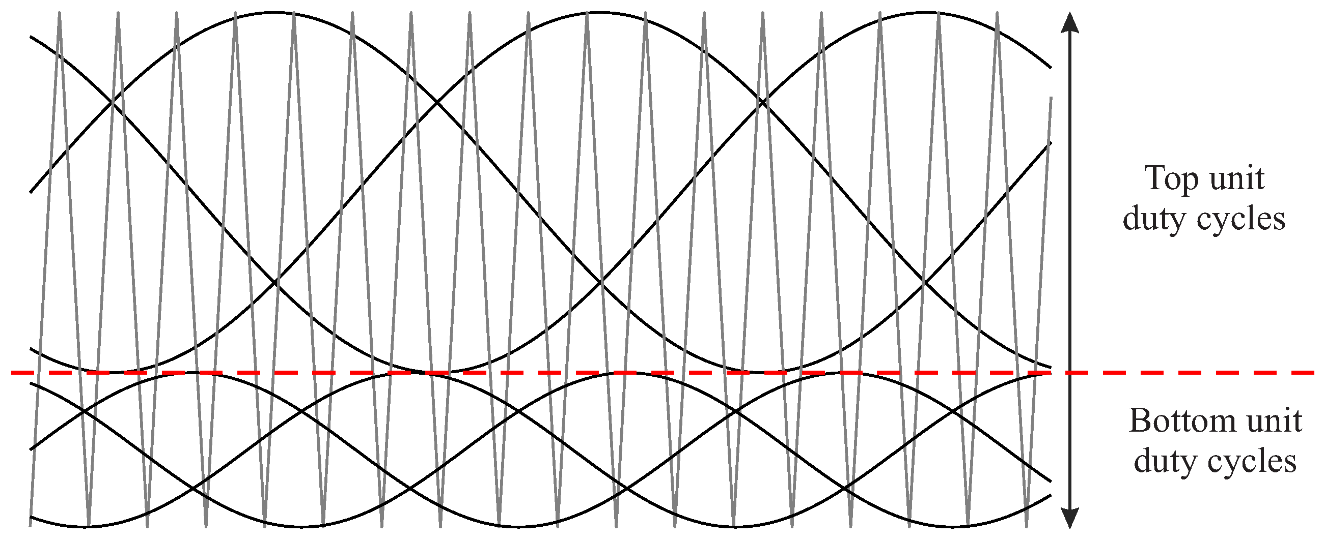
  • Reduced battery current ripple through phase-shift in the triangular carrier, resulting in increased battery lifespan by reducing the strain caused by high-frequency currents.
The rest of this paper is organized as follows: Section 2 introduces the proposed propulsion system for electric tramways, centered on the NSI converter; Section 3 details the converter’s control system and the design of the energy storage system; Section 4 presents and discusses the results; finally, Section 5 provides the conclusions drawn from the study.

2. Proposed Nine-Switch Multiport Scheme Applied to Battery-Powered Tramway

The nine-switch converter proposed by [40] along with the traditional VSI enables bidirectional conversion between DC and AC, offering control over amplitude and frequency. As shown in Figure 3, the NSI converter incorporates nine switches ( S 1 , S 2 , S 3 , S 4 , S 5 , S 6 , S 7 , S 8 , and S 9 ), facilitating the generation of two sets of three-phase outputs that can be seen as two VSI units (referred to as the top and bottom units). Each unit receives reference signals v a , v b , and v c for the top unit and v r , v s , and v t for the bottom unit, then compares them with a high-frequency triangular carrier wave.
Because the NSI converter has two three-phase outputs that shares the same DC link, a limitation arises regarding the reference signals. These signals must be distributed within the triangular area without overlapping with the reference signals, as shown in Figure 4. After comparing the reference signals to the triangular wave, the states of the upper switches ( S 1 , S 2 , S 3 ) and lower switches ( S 4 , S 5 , S 6 ) are generated. The states of the intermediate switches ( S 7 , S 8 , S 9 ) are then derived through a logical XOR operation between the states of the upper and lower switches.
In the proposed system, this converter is designed to work in a hybrid mode, handling both DC and AC power flows, as shown in Figure 5. As a multiport converter, it has three distinct ports, which are described below:
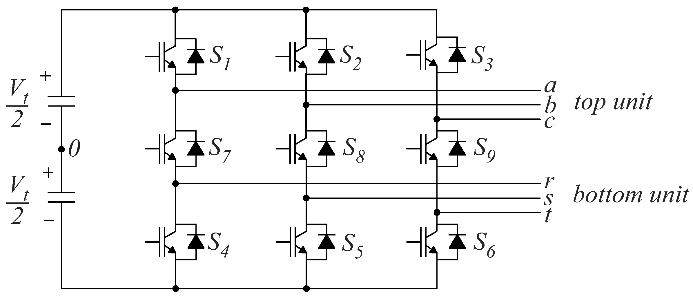
  • The first port is the top unit (represented as ➀ in Figure 5), which operates as an inverter, generating the three a, b, and c voltage phases necessary for driving three-phase motors.
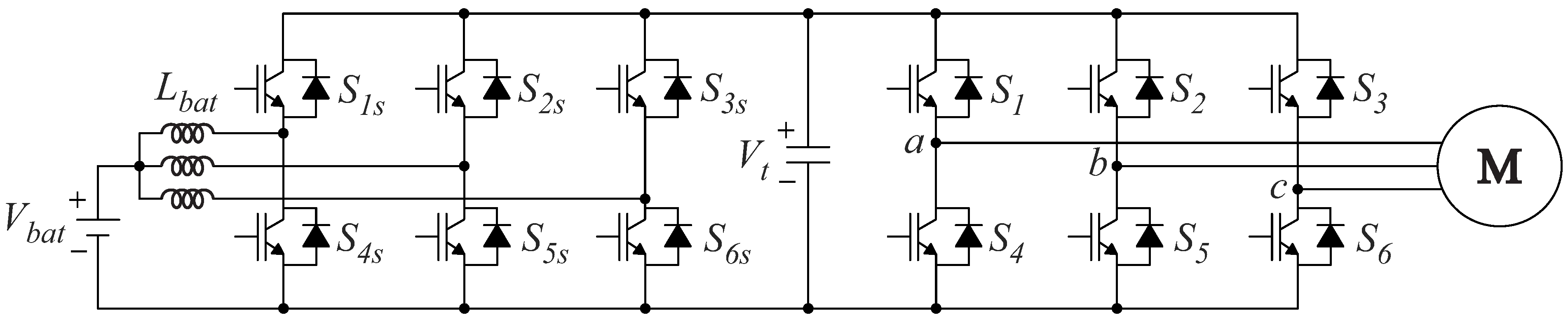
  • The second port corresponds to the bottom unit (represented as ➁ in Figure 5), operating as a half-bridge converter responsible for managing energy from a DC power source, which is an ESS with voltage V b a t . This configuration is a modification of the traditional SSI converter, where the diodes are replaced by inductors, enabling bidirectional current flow and facilitating the battery’s ability to absorb energy from regenerative braking. It additionally includes the reference node of the NSI, enabling the circulation of current through the ESS.
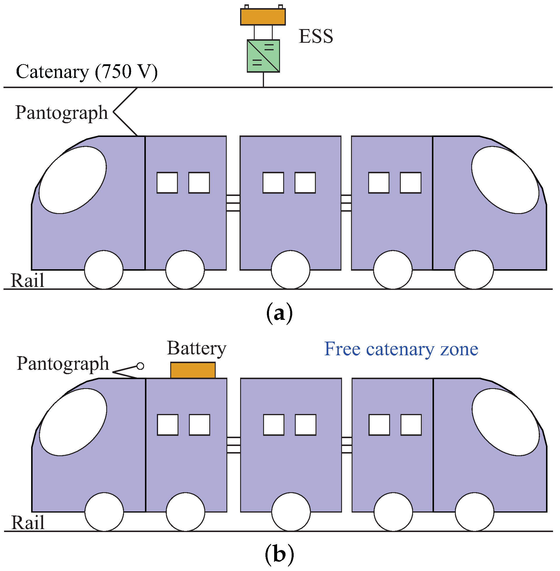
  • The third port (depicted as ➂ in Figure 5) comprises the DC link and the connection to the substation. When the tramway arrives at a station or garage with a recharging substation, the pantograph establishes the connection to the DC link.
When supplying power to the load, the proposed topology operates in boost mode, directing the power flow from the second port to the first port. During regenerative braking it switches to buck mode, allowing the ESS to receive energy. This converter addresses current leakage reduction by incorporating an output filter (composed of L f and C f ) connected to the DC link, thereby preventing current leakage through the parasitic capacitance C g .
In addition to the advantages described above, the proposed system can reduce the current ripple in the battery, which it achieves by implementing the carrier phase-shifting technique in one of the converter’s legs [41]. This shifts the carrier phase of the third leg by 180°, thereby reducing the input ripple current in the battery resulting from the sum of currents from each inductor L b a t .
From Figure 5, the battery current can be calculated as follows:
I b a t = I L b a t 1 + I L b a t 2 + I L b a t 3 .
Considering the same duty cycle applied to the lower switches of the proposed topology ( S 4 , S 5 , S 6 ), and as the carriers are implemented without phase shift, the currents I L b a t 1 , I L b a t 2 , and I L b a t 3 have the same waveform, which is shown in Figure 6a. As a consequence, according to (1), the maximum and minimum values of the battery current during normal operation are as follows:
max { I b a t } 0 p s = 3 · max { I L b a t } min { I b a t } 0 p s = 3 · min { I L b a t }
where the index 0 p s indicates that there is no phase shift in the carrier of the third leg. On the other hand, when considering a 180° phase shift in the carrier of the third leg, according to (1), the maximum and minimum values of the battery current during normal operation become
max { I b a t } 180 p s = 2 · max { I L b a t } + min { I L b a t } min { I b a t } 180 p s = 2 · min { I L b a t } + max { I L b a t } .
Because max { I L b a t } > min { I L b a t } , we have max { I b a t } 0 p s > max { I b a t } 180 p s and min { I b a t } 0 p s < min { I b a t } 180 p s . Consequently, with respect to the presence of a phase shift in the third leg of the converter, we have
Δ I b a t for 180 phase shift < Δ I b a t for no phase shift .
Figure 6 illustrates this reduction in the ripple of the battery current, where a duty cycle of 0.5 is the best-case scenario for ripple reduction, making the charging time of the inductor equal to its discharging time.

3. Design of Components for the Proposed System

In light of the application of the proposed system in electric tramways, it is imperative to outline the system components, including the power supply, converter, and load, which are shown in Figure 7. Beginning with the load aspect, the converter is used to drive the traction of the motors responsible for providing motion to the tramway. These motors present a variable energy consumption profile as the tramway transitions through different states such as acceleration, constant speed, and deceleration. These speed variations are predetermined, considering factors such as the known tramway route, the average number of passengers, and the total weight. Thus, disregarding emergency situations, it is possible to estimate the power profile of the electric tramway.
It is important to understand the load profile, as the converter must be designed to support the worst-case energy consumption scenario. Therefore, it is necessary to ensure proper dimensions of the inductors and DC link capacitance, as well as the ESS on the power supply side of the proposed topology. The adopted load profile is shown in Figure 8 [15]. The full-scale system operation parameters shown in Table 1 were used for dimensioning purposes.
It should be noted that the power parameters displayed in Table 1 reflect the characteristics of the ESS. However, as shown in Figure 7, multiple converters are used in parallel in electrical tramways. Thus, the power processed by each converter is only a fraction of that presented in Table 1.

3.1. Selecting the Battery Connection Inductance

Based on the maximum allowed current ripple for the input inductor, it is possible to determine the inductance to be used at the ESS connection port. In fact, according to [42], the required inductance can be calculated using the following equation:
L b a t = V b a t D b a t Δ I L b a t f p w m ,
where D b a t represents the duty cycle of the lower switches of the proposed topology. After the inductance is defined, a lower duty cycle D b a t results in a lower current ripple. However, in practical applications the value of D b a t is determined based on the current demanded by the load.

3.2. Selecting the DC Link Capacitance

The choice of the DC link capacitance is made with the aim of ensuring voltage oscillation within a tolerable range that will prevent damage to the ESS and load. In the case of an electric tramway, for instance, it ensures that the motors do not fail due to power fluctuations and that the ESS does not discharge below its minimum value during a load transient. Because the tramway load profile is variable, the design for a specific operating point may not properly meet the requirements during normal tramway operation, especially in extreme cases of regenerative braking and maximum speed. Therefore, the design process involved simulations conducted iteratively to determine the appropriate capacitance, following the steps below:
  • STEP 1: Set an initial capacitance for the DC link, its maximum and minimum voltage limits ( V t m a x and V t m i n ), and the acceptable response time for achieving capacitance energy equilibrium ( t s ).
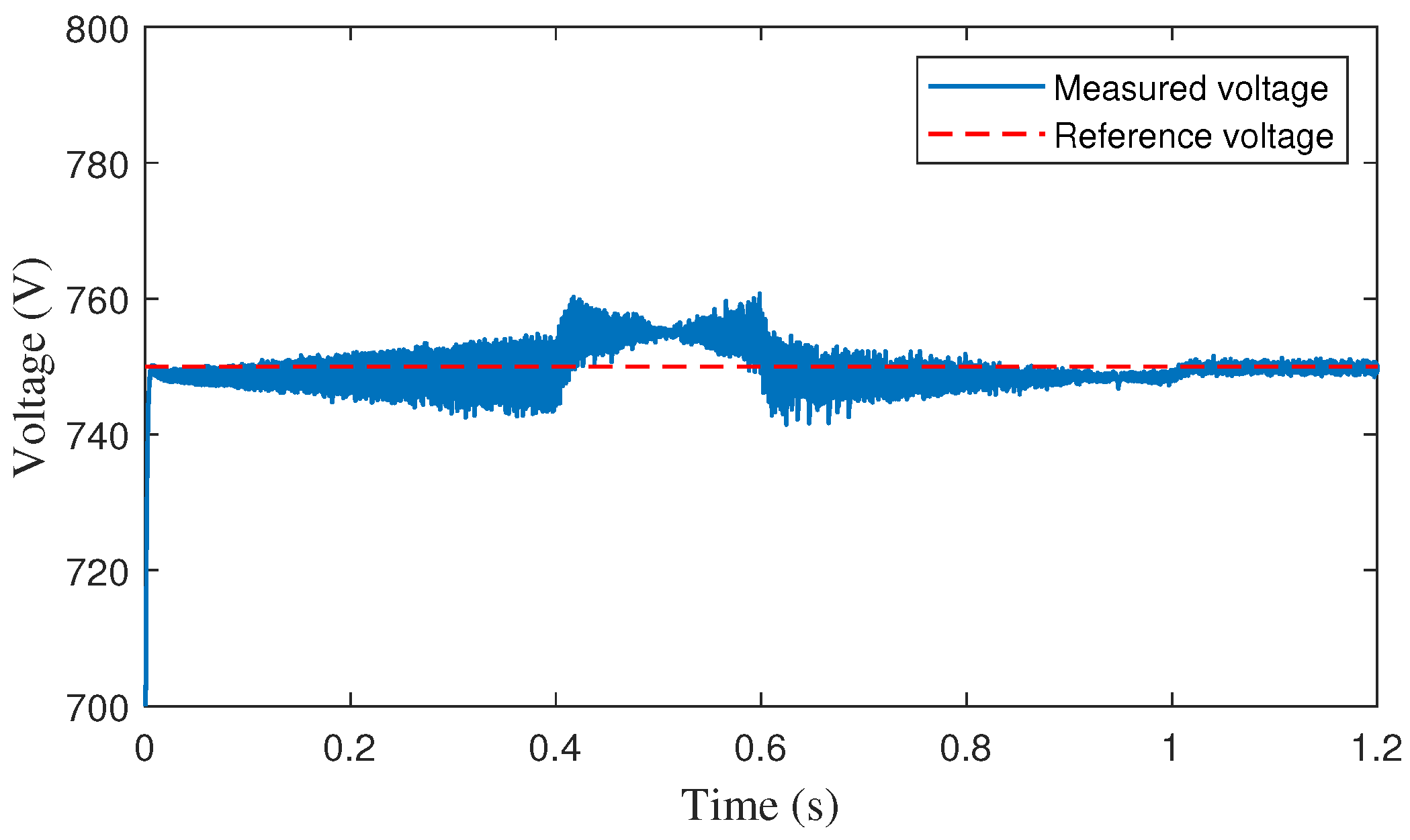
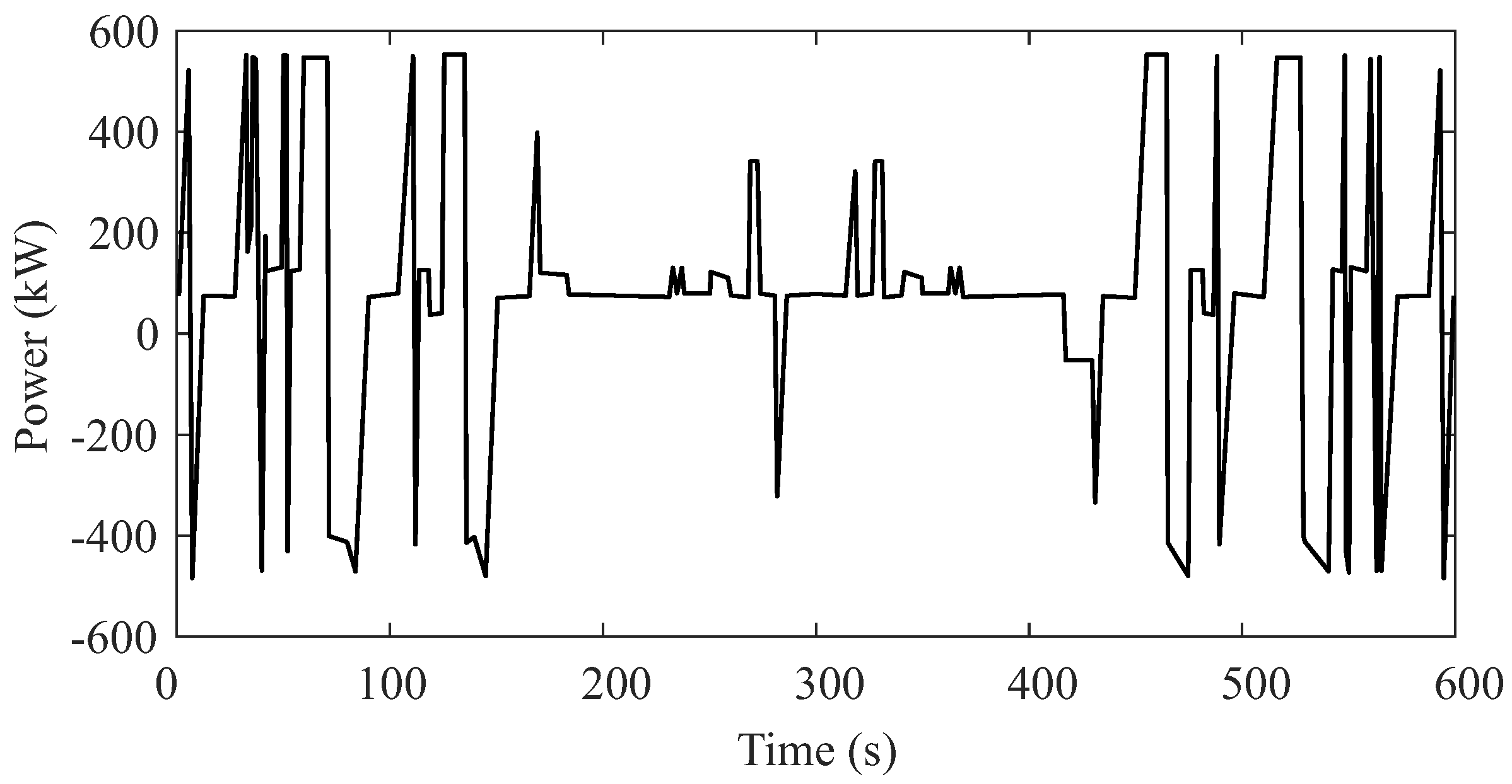
  • STEP 2: Execute the simulation and fine-tune the control parameters to achieve the shortest response time and minimal voltage fluctuation. This is evaluated for the entire load profile, considering all its abrupt variations.
  • STEP 3: For the considered load profile, the system designer must track the load variations that generate the following scenarios: (i) maximum voltage level for the DC link during a transient, and ( i i ) minimum voltage level for the DC link during a transient. Then, these maximum and minimum voltage levels must be measured and the response time of the control system obtained.
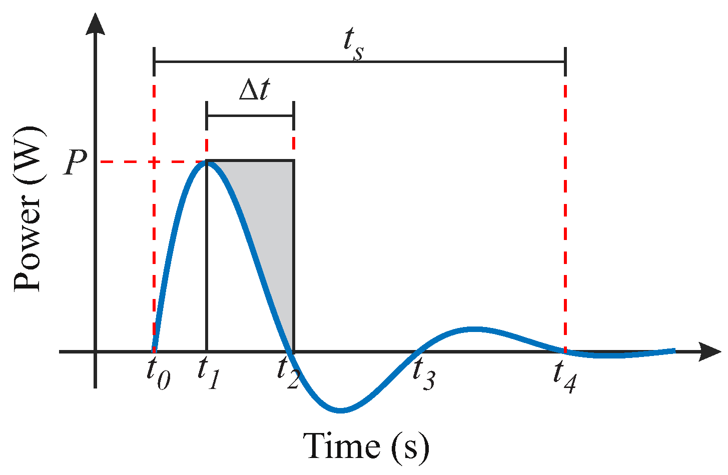
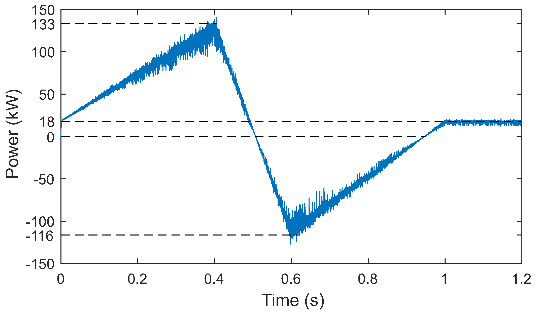
  • STEP 4: Compute the maximum and minimum energy variations observed for the transients detected in the simulation of STEP 3 (referred here to as Δ E t ( i ) and Δ E t ( i i ) ). Although these variables are traditionally calculated from the integral of power over time, they can be approximated by the area of the shaded triangle shown in Figure 9. Therefore, Δ E t can be calculated as follows:
    Δ E t = P Δ t 2 ,
    with P and Δ t being represented in Figure 9.
  • STEP 5: Use the maximum and minimum energy variations obtained in STEP 4 to compute the capacitances C t ( i ) and C t ( i i ) for the scenarios (i) and ( i i ) described in STEP 3. This can be done using the following equations:
    C t ( i ) = 2 Δ E t ( i ) V t m a x 2 V t n o m 2
    and
    C t ( i i ) = 2 Δ E t ( i i ) V t n o m 2 V t m i n 2 ,
    where V t n o m is the nominal voltage of the DC link.
  • STEP 6: Choose the greater value between C t ( i ) and C t ( i i ) as the new capacitance value, i.e.,
    C t = max ( C t ( i ) , C t ( i i ) ) .
  • STEP 7: Conduct a new simulation employing the newly determined capacitance value and repeat the control adjustment procedure.
  • STEP 8: Go back to STEP 2 and repeat the subsequent steps until the capacitance value calculated in the current iteration matches that obtained in the previous iteration, ensuring that the voltage and time limits are not violated.
The limits imposed for the voltage control response time and maximum overshoot for the voltage V t were set at 50 ms and 6%, respectively, corresponding to a voltage range of 705–795 V. Additionally, an initial capacitance value of 0.5 mF was used. The values obtained in each iteration are shown in Table 2. During the DC link capacitor design process, voltage violations occurred in the first three iterations. No violations occurred in the last two iterations, and the calculated capacitance values were identical. Theese results indicate that C t = 2 mF is adequate to satisfy the design criteria, concluding the iterative process.

3.3. Defining the ESS Characteristics

The battery design requires previous knowledge of the required power and energy density. Therefore, it is considered that the tramway consists of five cars supported by three bogies (railcar trucks on which the cars are mounted), with a maximum speed of 50 km/h and a maximum capacity of 279 seats [43]. Regarding the tramway’s electrical components, two bogies (ends) are motorized, with four motors and two converters each. Each converter has a nominal power of 300 kW, and each motor has a nominal power of 60 kW. Another aspect to consider is that, in addition to the motors, the tramway requires a constant power supply for ancillary services such as air conditioning, lighting, etc.
One way to determine the battery capacity is to use the tramway journey complete time ( t w a y ) and the average power delivered throughout the journey ( P m e d ), calculated as follows:
E b a t n o m = P m e d t w a y ,
where E b a t n o m is the nominal energy equivalent to the complete journey. However, it is also necessary to take into account that the tram will be powered at the last station of the outward journey. This stop represents the longest duration for passengers boarding and disembarking, lasting approximately 26 s. During this stop, the substation delivers the power profile shown in Figure 10. The equation for calculating the substation power is provided by
P s u b = | P m i n | + P a s ,
where P s u b is the substation power during recharging, | P m i n | represents the maximum power that the battery can absorb (which is equals to the minimum power presented in Table 1), and P a s is the ancillary services power demanded by the tramway. For the example presented in this paper, the calculated value of P s u b is 537.4 kW.
Subsequently, the complete load profile is determined with the inclusion of the substation, as shown in Figure 11. In this context, the accumulated battery energy ( E b a t ) to be delivered to the load can be obtained by
E b a t = 0 t w a y ( P s u b ( t ) P l o a d ( t ) ) d t .
Therefore, a minimum energy of 29.4 MJ or 8.2 kWh is obtained, representing the minimum energy necessary for the battery to power the tramway. In order to avoid deep discharges which could affect the battery lifespan, the state of charge (SOC) is a crucial factor. The SOC indicates the remaining energy within the battery and dictates when the next recharge is necessary. Moreover, to ensure high charge efficiency of the ESS, it is recommended for the SOC to be around 50% or within the range of 30% to 70% [44]. The SOC can be calculated according to the following equation:
S O C = 100 1 1 Q b a t 0 t i b a t ( t ) d t ,
where Q b a t represents the battery charge and i b a t is the battery current. In order to maintain the battery in a suitable SOC range (30% to 70%), an energy of 8.2 kWh is equivalent to 40% of the total capacity of 20.5 kWh. Thus, the complete tramway round trip will discharge up to a total of 30%, as shown in Figure 12.

3.4. Designing the LC Output Filter

Finally, it is necessary to design the LC output filter so as to attenuate the current leakage. The LC filter is designed based on the following requirements: limiting the voltage drop across the inductors to a maximum of 3.9%, resulting in
L f = 3.9 V a r m s 2 π f l I a r m s ,
and ensuring that the capacitors store no more than 22% of the reactive energy relative to the total power, demanding a capacitance of
C f = 0.22 P 6 π f l V a r m s 2 .
In the above equations, L f is the per-phase inductance of the output filter, V a r m s is the RMS voltage across the load, f l is the frequency at the load, I a r m s is the RMS current at the load, C f is the per-phase capacitance of the output filter, and P is the total power.

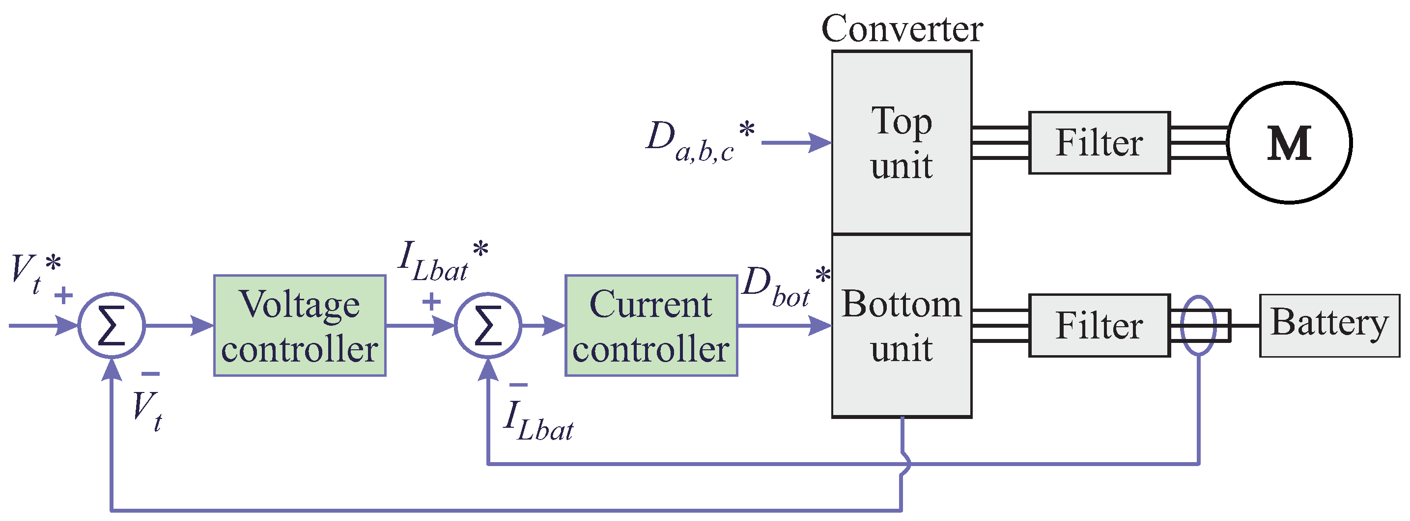
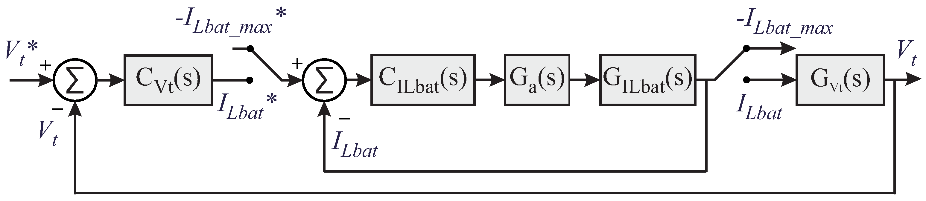
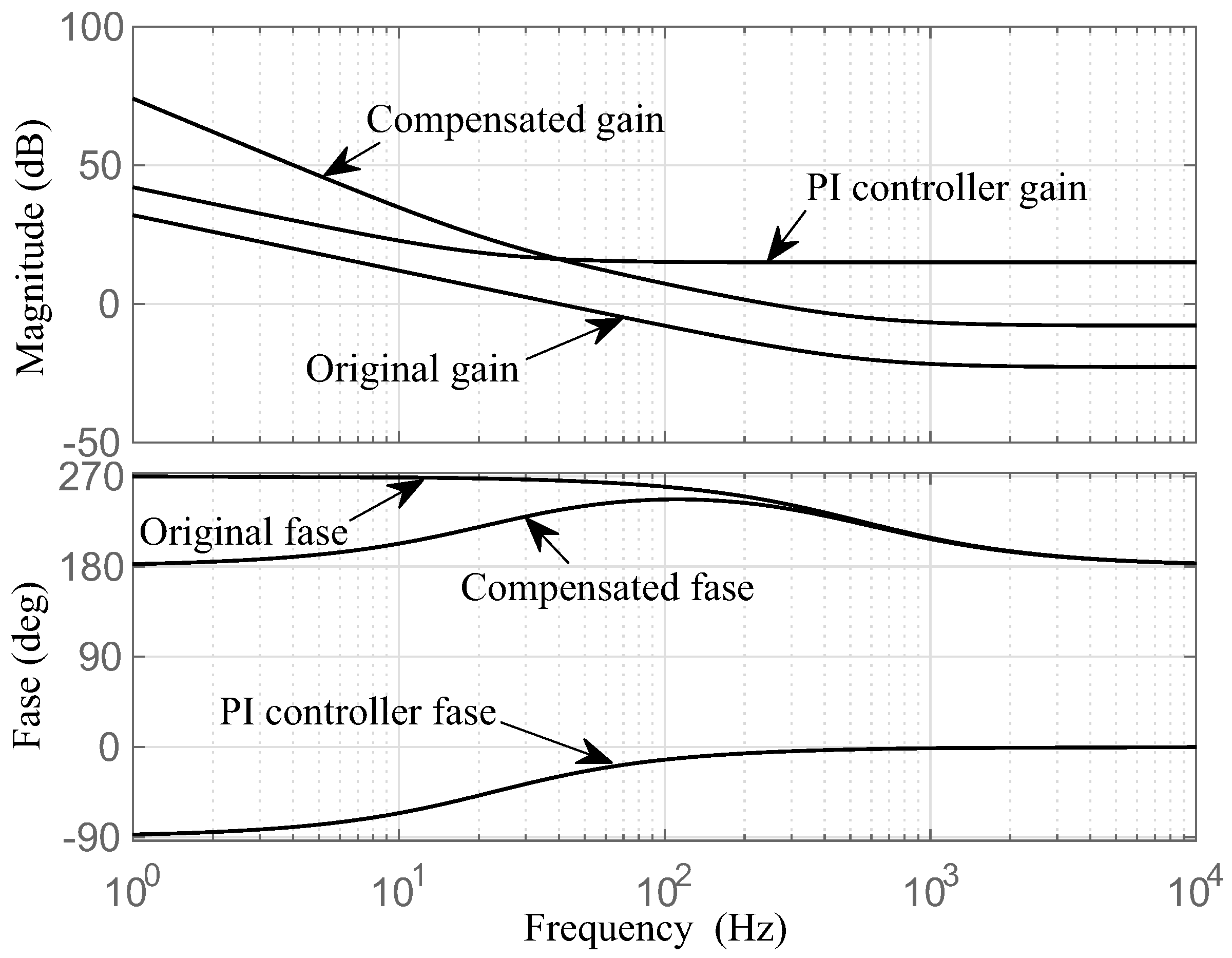
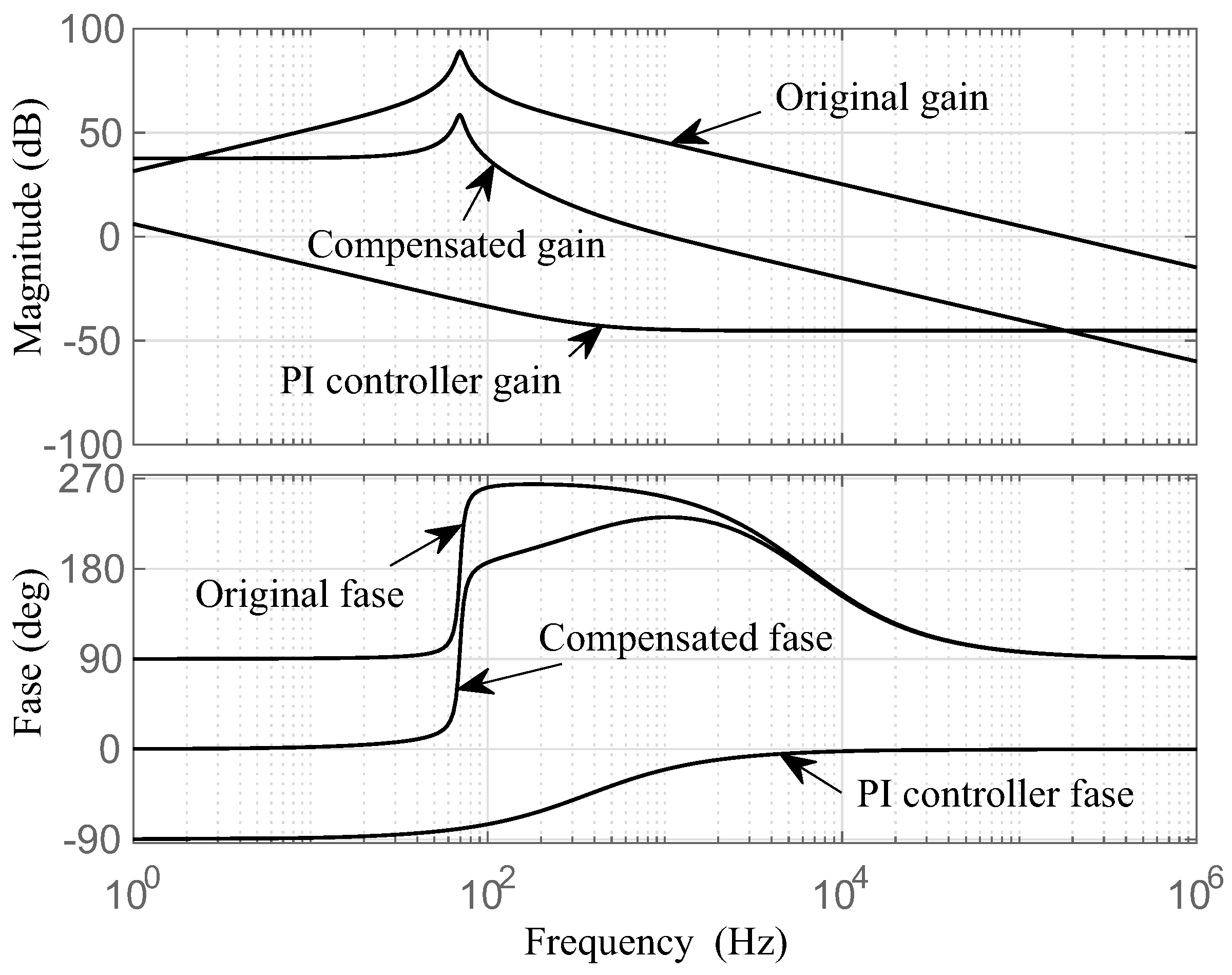
4. Design of the Control Structure for the Proposed System

The proposed system enables driving a three-phase motor using a nine-switch multiport converter. In this converter, there are two energy processing units (top and bottom) that can be independently activated, as shown in the Figure 13.
The top unit is responsible for driving the three-phase motor, where speed and torque control can be used to increase the precision of motor operation. However, in this work open-loop control is used, representing the steady-state dynamics with load variation from the real electric tram load profile.
The control assigned to the bottom unit is responsible for regulating the DC link voltage and the current in the battery, as shown in the diagram in Figure 14. For the control system of the converter connected to the battery, a dual-loop control is employed, considering that the elements responsible for the system dynamics ( L b a t and C t ) possess energies of different magnitudes. Additionally, with a dual-loop system it is possible to achieve a larger bandwidth, providing a faster and more damped response compared to a single-loop control system. Therefore, in order to obtain better control dynamics with the dual loop it is appropriate for the inner loop (current) to have a higher bandwidth than the outer loop (voltage), meaning that the inner loop dynamics need to be faster. However, when the tramway is stopped at the battery recharging station, this control strategy is switched to operate with only the inner current loop receiving the reference current ( I L b a t m a x ) value. This control switching occurs because the substation supplies the energy and controls the DC link voltage when the tramway is at the battery recharging station.
Figure 15 illustrates the Bode diagram of the voltage outer loop Open-Loop Transfer Function (OLTF). In the stability analysis, it can be observed from the magnitude plot that when crossing 0 dB (the crossing frequency) the phase plot exhibits a phase margin greater than −180°. The selected voltage controller can be easily adjusted by determining a bandwidth of 203 Hz with a phase margin of 63.4°. The Bode diagram analysis of the inner current loop is shown in Figure 16. The obtained bandwidth in the battery current loop OLTF is 1.07 kHz with a phase margin of 51.5°, which indicates stability.
A stability analysis was carried out by varying the load power and examining the rightmost pole of the voltage closed-loop transfer function (CLTF). As the power increases, the real part of the pole shifts to the right half-plane (RHP), indicating instability for power levels greater than three times the designed value. This analysis is shown in Figure 17. In the battery current CLTF analysis, a duty cycle variation between 0 and 1 proves that the real part of the rightmost pole remains in the left half-plane (LHP) for all possible values of D b a t , indicating system stability even when entering saturation. This last analysis is shown in Figure 18.

5. Simulation Results for the Real-Scale System

In order to test the control system, simulations were conducted in MATLAB/Simulink using a load profile containing all possible tramway operation scenarios: acceleration, regenerative braking, and stopping at the station for battery recharging. The parameters for the designed components of the switched converter are shown in Table 3. The electric tramway under study has four converters distributed in the wagons; therefore, the simulations were performed for the equivalent of one converter (25% of the total power). A reduction in the time scale of the simulation was performed to accelerate them while ensuring that the component dynamics were not affected. The aforementioned phase-shift PWM technique was applied to reduce the current ripple in the battery.
The tramway load profile used to test the control system is shown in Figure 19. In this profile, the tramway starts out stationary with a load of 17.9 kW, including ancillary services such as lighting and air conditioning. The tram then begins its course, accelerating until it reaches a power of 133 kW. The braking process occurs until the tram provides a maximum power of −116 kW. During this period, the energy from regenerative braking is used to charge the battery. Finally, the tram stops at the station and recharges the battery while the passengers are boarding/alighting. The tram recharge profile provided by the substation is presented in Figure 20.
The implemented DC link voltage control is shown in Figure 21. The voltage follows a predicted profile due to the power variation that occurs in the load, as depicted in Figure 19. It can be observed that this voltage variation remains within acceptable limits and that the oscillation increases as power increases during the tram’s acceleration. Furthermore, the DC link voltage rises with the increase in the energy absorbed by the battery during regenerative braking, quickly stabilized upon arrival at the station (at time 1s) and initiating the battery recharging process with constant power. In steady-state conditions, even while the tram ancillary services consume energy and battery recharging occurs at a constant power, the DC link voltage remains stable with zero steady-state error.
The flexibility in the operating point variation is crucial for battery current control, as it avoids current peaks with abrupt changes in the load. The battery charge and discharge profile is shown in Figure 22. It is worth mentioning that the battery is receiving energy from the tram’s regenerative braking during the period when the current becomes negative. As mentioned earlier, at time 1 s the pantograph is activated to connect to the substation for battery recharging, which is indicated by the constant negative current, showing that the battery is receiving energy. The maximum current ripple is 82 A peak-to-peak.
The battery current has a ripple, which is as designed; however, it is possible to reduce this ripple by applying the triangular carrier phase shift technique in one of the converter phases. Thus, the third leg carrier was phased by 180° in the simulation. As depicted in Section 2, by shifting the carrier, the current flowing through the third leg is shifted from the other two legs. Because the current on the battery side is the sum of the currents in each leg, the result is a total current with a lower ripple. This is illustrated in Figure 23, which shows a 58% reduction in current ripple. Without phasing the carrier, the current has a ripple of 82 A peak-to-peak; by phasing the carrier, this is reduced to a ripple of 34 A peak-to-peak. This reduction in current variation is suitable to avoid battery wear.
The disadvantage of the carrier phase-shifting technique can be observed in the PWM modulation of the output three-phase voltages. In Figure 24, the three-phase voltages without carrier phase shifting have three levels; when the carrier of the third leg is phase-shifted by 180°, as shown in Figure 25, there is a reduction in the voltage levels related to the third leg ( V b c and V c a ). However, this modification does not affect the filtered voltages, as they remain sinusoidal.
Finally, the converter output currents that supply the electric tramway are shown in Figure 26. The results show that the three-phase currents have amplitudes following the tramway power profile and present a sinusoidal shape.

6. Simulation and Experimental Results of Reduced-Scale System

Simulations and reduced-scale experiments were conducted to validate the proposed system. The parameters are shown in Table 4. The dSPACE controller with a DS1005 processor was implemented for the proposed system with a nominal power of 180 W. Both simulated and experimental results used a DC source to represent the battery. The reduced-scale experiments used the Chroma DC source.
The implemented experimental setup is shown in Figure 27. The reduced-scale simulation results were validated by comparing them with the experimental results presented subsequently.
As mentioned in the previous section, the DC link is shared between the converter’s top and bottom units. Therefore, the inverter modulation index used to generate the required voltages for the load can vary depending on the battery’s voltage level. Moreover, the two modulation signals cannot overlap. For this reason, the duty cycles of the bottom and top units remain separate, as shown in Figure 28a,b. These figures show that the experimental results are consistent with the simulated ones, where the duty cycles of the top unit ( D S 1 , D S 2 , D S 3 ) do not overlap with those of the bottom unit ( D S 4 , D S 5 , D S 6 ).
The line voltages generated at the converter output to power the load are shown in Figure 29a,b. The phase voltages at the load measured after the LC filter are shown in Figure 30a,b and exhibit a sinusoidal profile, indicating correct operation of both the PWM and the LC filter. Therefore, the NSI converter performs the inversion function properly in the top unit without being affected by the voltage and current control in the bottom unit.
The converter operates normally in the steady state without using the passive filter. This permits a low-impedance path for high-frequency currents, as it maintains the DC link voltage controlled at 100 V. The simulation and experimental results of the DC link voltage, battery current and input power without passive filter are presented in Figure 31a and Figure 31b, respectively. The battery current control maintains the current at around 5.4 A, which is necessary to ensure DC link charging and to supply the load. Additionally, the input power can be obtained, corroborating that the experimentally assembled system consumes an average of 181 W. Finally, it can be seen that both controls are stable and without interference from the top unit.
Figure 32a,b presents the current leakage results for the three-phase load without using the low-impedance path connected to the DC link. The results show an RMS value around 570 mA, which poses a long-term risk to the motor windings and bearings.
New experiments were conducted by applying the low-impedance path, i.e., connecting the passive filter, in order to control the DC link voltage at 100 V. The simulated and experimental results for the DC link voltage, battery current, and input power with the passive filter are presented in Figure 33a and Figure 33b, respectively. The results demonstrate that the battery current control maintains the current at around 5.45 A while providing suitable DC link control performance and without interference from the top unit.
Conversely, the addition of the filter proves to be advantageous when comparing Figure 32 and Figure 34. The experimental results present a reduced current leakage value of 3 mA, which is around 190 times lower than the results without the filter, reducing the risk of damage to the motors.
In conclusion, the NSI converter applied to a three-phase load powered by a battery has a suitable operation with and without a passive filter. Moreover, from the load side, using the passive filter is more interesting due to the significant reduction in the leakage current.

7. Conclusions

This paper proposes an integrated solution for an electric tramway, consisting of a multi-port NSI-based converter powered by a battery for driving a three-phase induction motor. In addition, the proposal implements a passive output filter to reduce current leakage that can circulate through the power drive. The proposed system presents a connection to the catenary for recharging the battery upon arrival at the tramway station. The converter topology reduces the current ripple in the battery using a specific phase-shift PWM. The components, battery power, and battery capacity were designed for a known real tramway power profile operating with a closed-loop control system. Simulation results at both real and reduced scale along with experimental results at reduced scale demonstrate that the proposed solution is effective in achieving a compact system with a reduced component count in the converter. Furthermore, the current leakage in the three-phase induction motor is decreased from 500 mA to 3 mA, enhancing the longevity of the electric tramway drive system. Finally, the results show a reduction in the battery current ripple with the phase-shift PWM strategy from 82 A to 34 A.

Author Contributions

Conceptualization, A.D.D.A.; formal analysis, A.D.D.A., F.B., C.R., C.A.C. and G.M.S.A.; funding acquisition, F.B.; investigation, A.D.D.A., F.B. and C.R.; supervision, A.D.D.A., F.B., C.R., R.C.N. and G.M.S.A.; validation, A.D.D.A., C.A.C. and R.C.N.; writing—original draft, A.D.D.A.; writing—review and editing, A.D.D.A., F.B. and C.A.C. All authors have read and agreed to the published version of the manuscript.

Funding

This research was partially supported for the Conselho Nacional de Desenvolvimento Científico e Tecnológico (CNPq), the Coordenação de Aperfeiçoamento de Pessoal de Nível Superior (CAPES) and the Instituto Nacional de Ciência e Tecnologia em Geração Distribuída - INCT-GD (CNPq Grant 465640/2014-1, CAPES Grant 23038.000776/2017-54 and FAPERGS Grant 17/2551-0000517-1) for the financial support.

Data Availability Statement

Data is contained within the article.

Acknowledgments

The authors gratefully acknowledge the administrative and technical support of the Grupo de Eletrônica de Potência e Acionamentos Elétricos (GEPAE), the Universidade Federal de Pernambuco (UFPE), the Grupo de Eletrônica de Potência e Controle (GEPOC) and the Universidade Federal de Santa Maria (UFSM).

Conflicts of Interest

The authors declare no conflicts of interest.

Abbreviations

The following abbreviations are used in this manuscript:
ACAlternating Current
CMVCommon Mode Voltage
CLTFClose-Loop Transfer Function
DCDirect Current
ESSEnergy Storage System
LCInductor and Capacitor
LHPLeft Half-Plane
NSINine-Switch Inverter
OLTFOpen-Loop Transfer Function
PWMPulse Width Modulation
RHPRight Half-Plane
RMSRoot Mean Square
SOCState of Charge

References

  1. Lee, H.; Cho, D.H. Energy Cost Minimization Based on Decentralized Reinforcement Learning with Feedback for Stable Operation of Wireless Charging Electric Tram Network. IEEE Syst. J. 2021, 15, 586–597. [Google Scholar] [CrossRef]
  2. Mohanraj, D.; Gopalakrishnan, J.; Chokkalingam, B.; Mihet-Popa, L. Critical Aspects of Electric Motor Drive Controllers and Mitigation of Torque Ripple—Review. IEEE Access 2022, 10, 73635–73674. [Google Scholar] [CrossRef]
  3. Xiao, Z.; Chen, H.; Guo, J.; Wang, Q.; Sun, P.; Feng, X. Joint Optimization of Speed and Voltage Trajectories for Hybrid Electric Trams. IEEE Trans. Ind. Appl. 2021, 57, 6427–6439. [Google Scholar] [CrossRef]
  4. Kim, J.; Ryu, J.; Kim, G.; Lee, J.; Chang, S.; Lee, C.; Kim, J.; Oh, Y.; Lee, H.; Kim, J. A Proposed Fast Charging and High-Power System for Wireless Railway Trains Adopting the Input Voltage Sharing Topology and the Balancing Control Scheme. IEEE Trans. Ind. Electron. 2020, 67, 6407–6417. [Google Scholar] [CrossRef]
  5. Brenna, M.; Foiadelli, F.; Zaninelli, D. Introduction to Railway Systems. In Electrical Railway Transportation Systems; Wiley: Hoboken, NJ, USA, 2018; pp. 1–16. [Google Scholar] [CrossRef]
  6. Simiyu, P.; Davidson, I.E. MVDC Railway Traction Power Systems; State-of-the Art, Opportunities, and Challenges. Energies 2021, 14, 4156. [Google Scholar] [CrossRef]
  7. Polater, N.; Tricoli, P. Technical Review of Traction Drive Systems for Light Railways. Energies 2022, 15, 3187. [Google Scholar] [CrossRef]
  8. Graber, G.; Calderaro, V.; Galdi, V.; Piccolo, A.; Lamedica, R.; Ruvio, A. Techno-economic Sizing of Auxiliary-Battery-Based Substations in DC Railway Systems. IEEE Trans. Transp. Electrif. 2018, 4, 616–625. [Google Scholar] [CrossRef]
  9. Xiao, Z.; Sun, P.; Wang, Q.; Zhu, Y.; Feng, X. Integrated Optimization of Speed Profiles and Power Split for a Tram with Hybrid Energy Storage Systems on a Signalized Route. Energies 2018, 11, 478. [Google Scholar] [CrossRef]
  10. Wang, Y.; Yang, Z.; Li, F. Optimization of Energy Management Strategy and Sizing in Hybrid Storage System for Tram. Energies 2018, 11, 752. [Google Scholar] [CrossRef]
  11. Kim, J.; Kim, J.; Lee, C.; Kim, G.; Lee, H.; Lee, B. Optimal Capacity Estimation Method of the Energy Storage Mounted on a Wireless Railway Train for Energy-Sustainable Transportation. Energies 2018, 11, 986. [Google Scholar] [CrossRef]
  12. Arboleya, P.; Bidaguren, P.; Armendariz, U. Energy Is On Board: Energy Storage and Other Alternatives in Modern Light Railways. IEEE Electrif. Mag. 2016, 4, 30–41. [Google Scholar] [CrossRef]
  13. Yang, Y.; Zhang, W.; Wei, S.; Wang, Z. Optimal Sizing of On-Board Energy Storage Systems and Stationary Charging Infrastructures for a Catenary-Free Tram. Energies 2020, 13, 6227. [Google Scholar] [CrossRef]
  14. Radu, P.V.; Lewandowski, M.; Szelag, A. On-Board and Wayside Energy Storage Devices Applications in Urban Transport Systems—Case Study Analysis for Power Applications. Energies 2020, 13, 2013. [Google Scholar] [CrossRef]
  15. Garcia, P.; Fernandez, L.M.; Garcia, C.A.; Jurado, F. Energy Management System of Fuel-Cell-Battery Hybrid Tramway. IEEE Trans. Ind. Electron. 2010, 57, 4013–4023. [Google Scholar] [CrossRef]
  16. Chymera, M.; Renfrew, A.C.; Barnes, M.; Holden, J. Simplified Power Converter for Integrated Traction Energy Storage. IEEE Trans. Veh. Technol. 2011, 60, 1374–1383. [Google Scholar] [CrossRef]
  17. Jayasinghe, S.D.G.; Vilathgamuwa, D.M.; Madawala, U.K. Diode-Clamped Three-Level Inverter-Based Battery/Supercapacitor Direct Integration Scheme for Renewable Energy Systems. IEEE Trans. Power Electron. 2011, 26, 3720–3729. [Google Scholar] [CrossRef]
  18. İnci, M.; Büyük, M.; Demir, M.H.; İlbey, G. A review and research on fuel cell electric vehicles: Topologies, power electronic converters, energy management methods, technical challenges, marketing and future aspects. Renew. Sustain. Energy Rev. 2021, 137, 110648. [Google Scholar] [CrossRef]
  19. Ogasa, M.; Taguchi, Y. Power electronics technologies for a lithium ion battery tram. In Proceedings of the 2007 Power Conversion Conference, Nagoya, Japan, 2–5 April 2007; pp. 1369–1375. [Google Scholar] [CrossRef]
  20. Lin, Y.S.; Hu, K.W.; Yeh, T.H.; Liaw, C.M. An Electric-Vehicle IPMSM Drive With Interleaved Front-End DC/DC Converter. IEEE Trans. Veh. Technol. 2016, 65, 4493–4504. [Google Scholar] [CrossRef]
  21. Mande, D.; Trovão, J.P.F.; Ta, M.C.; Do, T.V. Dual-Source Bidirectional Quasi-Z-Source Inverter Development for Off-Road Electric Vehicles. World Electr. Veh. J. 2022, 13, 174. [Google Scholar] [CrossRef]
  22. Abdelhakim, A.; Mattavelli, P.; Spiazzi, G. Three-Phase Split-Source Inverter (SSI): Analysis and Modulation. IEEE Trans. Power Electron. 2016, 31, 7451–7461. [Google Scholar] [CrossRef]
  23. Thanakam, T.; Kumsuwan, Y. A Novel On-Board Battery Charger Configuration Based on Nine-Switch Converter fed Open-End Winding AC Motor Drive for Plug-In Electric Vehicles. In Proceedings of the 2021 24th International Conference on Electrical Machines and Systems (ICEMS), Gyeongju, Republic of Korea, 31 October–3 November 2021; pp. 988–991. [Google Scholar] [CrossRef]
  24. Salem, A.; Narimani, M. Nine-Switch Current-Source Inverter-Fed Asymmetrical Six-Phase Machines Based on Vector Space Decomposition. In Proceedings of the 2020 IEEE Energy Conversion Congress and Exposition (ECCE), Detroit, MI, USA, 11–15 October 2020; pp. 1951–1956. [Google Scholar] [CrossRef]
  25. Cury Alves dos Santos, S.T.; Ubaldo Guazzelli, P.R.; de Castro, A.G.; Freitas Vieira, B.; de Andrade Pinto, S.; Luis de Aguiar, M. Grid-Connected Variable Speed Driven Squirrel-Cage Induction Motor Through a Nine-Switch AC/AC Converter with Leading Power Factor. In Proceedings of the IECON 2020 the 46th Annual Conference of the IEEE Industrial Electronics Society, Singapore, 18–21 October 2020; pp. 979–984. [Google Scholar] [CrossRef]
  26. Abbache, M.A.; Tabbache, B.; Kheloui, A. Direct torque control of nine switches inverter—Dual induction motors. In Proceedings of the 22nd Mediterranean Conference on Control and Automation, Palermo, Italy, 16–19 June 2014; pp. 810–815. [Google Scholar] [CrossRef]
  27. Kandasamy, V.; Manoj, R. Grid integration of AC and DC energy resources using multi-input nine switch matrix converter. In Proceedings of the 2014 International Conference on Green Computing Communication and Electrical Engineering (ICGCCEE), Coimbatore, India, 6–8 March 2014; pp. 1–4. [Google Scholar] [CrossRef]
  28. Qin, Z.; Loh, P.C.; Blaabjerg, F. Power loss benchmark of nine-switch converters in three-phase online-UPS application. In Proceedings of the 2014 IEEE Energy Conversion Congress and Exposition (ECCE), Pittsburgh, PA, USA, 14–18 September 2014; pp. 1180–1187. [Google Scholar] [CrossRef]
  29. Dos Santos, E.C.; Jacobina, C.B.; da Silva, O.I. Six-phase machine drive system with nine-switch converter. In Proceedings of the IECON 2011—37th Annual Conference of the IEEE Industrial Electronics Society, Melbourne, VIC, Australia, 7–10 November 2011; pp. 4204–4209. [Google Scholar] [CrossRef]
  30. Dehghan, S.M.; Amiri, A.; Mohamadian, M.; Andersen, M.A. Modular space-vector pulse-width modulation for nine-switch converters. IET Power Electron. 2013, 6, 457–467. [Google Scholar] [CrossRef]
  31. Genu, L.G.B.; Limongi, L.R.; Cavalcanti, M.C.; Bradaschia, F.; Neves, F.A.S. Transformerless hybrid power filter topologies derived from nine-switch inverter. In Proceedings of the 2015 IEEE 13th Brazilian Power Electronics Conference and 1st Southern Power Electronics Conference (COBEP/SPEC), Fortaleza, Brazil, 29 November–2 December 2015; pp. 1–6. [Google Scholar] [CrossRef]
  32. Hou, C.C.; Wang, P.W.; Chen, C.C.; Chang, C.W. Common Mode Voltage Reduction in Four-Leg Inverter with Multicarrier PWM Scheme. In Proceedings of the 2019 10th International Conference on Power Electronics and ECCE Asia (ICPE 2019—ECCE Asia), Busan, Republic of Korea, 27–30 May 2019; pp. 3223–3228. [Google Scholar] [CrossRef]
  33. Dianguo, X.; Qiang, G.; Wei, W. Design of a Passive Filter to Reduce Common-Mode and Differential-Mode Voltage Generated by Voltage-Source PWM Inverter. In Proceedings of the IECON 2006—32nd Annual Conference on IEEE Industrial Electronics, Paris, France, 6–10 November 2006; pp. 2483–2487. [Google Scholar] [CrossRef]
  34. Hota, A.; Agarwal, V. A New H8 Inverter Topology With Low Common Mode Voltage and Phase Current THD for 3-φ Induction Motor Drive Applications. IEEE Trans. Ind. Appl. 2022, 58, 6245–6252. [Google Scholar] [CrossRef]
  35. Zhang, K.; Chung, H.S.H.; Wu, W. Design and Assessment of a New Active CM Filtering Architecture for PWM Inverter-Fed Motor Drive Systems. IEEE Trans. Power Electron. 2023, 38, 1819–1830. [Google Scholar] [CrossRef]
  36. Shen, J.X.; Sun, W.; Huang, X.Q. A DC link switch-based common mode voltage reduction scheme in PWM inverter drives. In Proceedings of the 2015 International Conference on Sustainable Mobility Applications, Renewables and Technology (SMART), Kuwait, Kuwait, 23–25 November 2015; pp. 1–7. [Google Scholar] [CrossRef]
  37. Porkia, H.A.; Adabi, J.; Zare, F. Reduction of Zero-Sequence and Differential-Mode Circulating Currents and Common-Mode Voltage in Parallel PWM Converters. IEEE Trans. Ind. Electron. 2023, 70, 4038–4047. [Google Scholar] [CrossRef]
  38. Hakami, S.S.; Halabi, L.M.; Lee, K.B. Dual-Carrier-Based PWM Method for DC-Link Capacitor Lifetime Extension in Three-Level Hybrid ANPC Inverters. IEEE Trans. Ind. Electron. 2023, 70, 3303–3314. [Google Scholar] [CrossRef]
  39. Hasanzad, F.; Rastegar, H.; Pichan, M. Performance analysis of reduced common-mode voltage space vector modulation techniques for three-phase four-leg voltage-source inverter. In Proceedings of the 2018 9th Annual Power Electronics, Drives Systems and Technologies Conference (PEDSTC), Tehran, Iran, 13–15 February 2018; pp. 65–70. [Google Scholar] [CrossRef]
  40. Liu, C.; Wu, B.; Zargari, N.R.; Xu, D.; Wang, J. A Novel Three-Phase Three-Leg AC/AC Converter Using Nine IGBTs. IEEE Trans. Power Electron. 2009, 24, 1151–1160. [Google Scholar] [CrossRef]
  41. Nguyen, T.; Phan Quoc, D.; Dao, N.D.; Lee, H.H. Carrier Phase-Shift PWM to Reduce Common-Mode Voltage for Three-Level T-Type NPC Inverters. J. Power Electron. 2014, 14, 1197–1207. [Google Scholar] [CrossRef]
  42. Erickson, R.W.; Maksimovic, D. Fundamentals of Power Electronics, 3rd ed.; Springer: Berlin/Heidelberg, Germany, 2020. [Google Scholar]
  43. CAF. Trams and Light Metros—Seville Metro Centro. 2022. Available online: https://www.caf.net/en/soluciones/proyectos/proyecto-detalle.php?p=70 (accessed on 14 March 2024).
  44. Linden, D.; Reddy, T.B. Handbook of Batteries, 3rd ed.; McGraw-Hill: New York, NY, USA, 2001. [Google Scholar]
Figure 1. Possible ESS configurations in electric tramways: (a) offboard; and (b) onboard.
Energies 17 01434 g001
Figure 2. Back-to-back converter applied to an electric railway.
Energies 17 01434 g002
Figure 3. Traditional nine-switch inverter.
Energies 17 01434 g003
Figure 4. Scalar PWM applied for a traditional NSI converter.
Energies 17 01434 g004
Figure 5. Proposed nine-switch multiport scheme applied to a battery-powered tramway.
Energies 17 01434 g005
Figure 6. Inductor current ( I L b a t ) and battery current ( I b a t ) (a) without phase shift and (b) with 180° phase shift in the carrier of the third leg.
Energies 17 01434 g006
Figure 7. Distribution of converters on an electric tramway.
Energies 17 01434 g007
Figure 8. Load profile adopted for dimensioning purposes.
Energies 17 01434 g008
Figure 9. Example of the power supplied/absorbed by the DC link during a load transition.
Energies 17 01434 g009
Figure 10. Recharging profile at the substation.
Energies 17 01434 g010
Figure 11. Load profile considering the substation.
Energies 17 01434 g011
Figure 12. Battery SOC for the considered example.
Energies 17 01434 g012
Figure 13. Complete block diagram of the control system for the proposed system.
Energies 17 01434 g013
Figure 14. Detailed block diagram of the control for the proposed system.
Energies 17 01434 g014
Figure 15. Bode diagram of the voltage control OLTF.
Energies 17 01434 g015
Figure 16. Bode diagram of the current control OLTF.
Energies 17 01434 g016
Figure 17. Stability analysis of the voltage control loop based on evaluation of the dominant dynamic pole of its CLTF. The poles represented in red indicate unstable conditions.
Energies 17 01434 g017
Figure 18. Stability analysis of the current control loop based on evaluating the dominant dynamic pole of its CLTF.
Energies 17 01434 g018
Figure 19. Load profile adopted in real-scale simulations.
Energies 17 01434 g019
Figure 20. Recharging profile at the substation adopted in real-scale simulations.
Energies 17 01434 g020
Figure 21. Load profile adopted in the simulations.
Energies 17 01434 g021
Figure 22. Current drain from the battery without reduced ripple.
Energies 17 01434 g022
Figure 23. Current drain from the battery with reduced ripple.
Energies 17 01434 g023
Figure 24. Converter output voltages without carrier phase shift.
Energies 17 01434 g024
Figure 25. Converter output voltages with carrier phase shift.
Energies 17 01434 g025
Figure 26. Converter output currents.
Energies 17 01434 g026
Figure 27. Experimental setup: (a) NSI, DC link, and sensors; (b) dSPACE and DC source; (c) signal conditioning circuit; (d) LC output filter and battery filter; (e) resistive load and leakage capacitance.
Energies 17 01434 g027
Figure 28. Duty cycles of the switches: (a) simulation results and (b) experimental results.
Energies 17 01434 g028
Figure 29. Output voltages: (a) simulation results and (b) experimental results.
Energies 17 01434 g029
Figure 30. Load voltages: (a) simulation results and (b) experimental results.
Energies 17 01434 g030
Figure 31. DC link voltage, battery current, and input power without the filter: (a) simulation results and (b) experimental results.
Energies 17 01434 g031
Figure 32. CMV and current leakage without the filter: (a) simulation results and (b) experimental results.
Energies 17 01434 g032
Figure 33. DC link voltage, battery current, and input power with the filter: (a) simulation results and (b) experimental results.
Energies 17 01434 g033
Figure 34. CMV and current leakage with the filter: (a) simulation results and (b) experimental results.
Energies 17 01434 g034
Table 1. Simulation parameters of the system.
SymbolParameterComponentValue
V b a t Battery voltageBattery375 V
V t DC link voltageConverters750 V
f p w m Switching frequencyConverters10 kHz
V a b Output line voltageConverters311 Vrms
Δ I L b a t Input inductor current rippleConverters27.2 A
P a v Average powerBattery192.74 kW
P m a x Maximum powerBattery532.7 kW
P m i n Minimum powerBattery−465.9 kW
P a s Ancillary services powerBattery71.5 kW
Table 2. DC link capacitance.
Iteration Δ E t V t max V t max Δ t V t max C t V t max Δ E t V t min V t min Δ t V t min C t V t min C t
(J)(V)(ms)(mF)(J)(V)(ms)(mF)(mF)
1301068 *1.31060522 *24141
225797 *10.6884570831.51.5
349796 *1.41.6507082.51.61.6
4497951.41.660708322
563794.51.41.860709322
* The imposed limit was violated.
Table 3. Simulation parameters.
SymbolParameterValue
V t DC link voltage750 V
V b a t Battery voltage375 V
V a b Output line voltage380 V
P a v Average power48.25 kW
P m a x Maximum power133.2 kW
P m i n Minimum power−116.5 kW
P a s Ancillary services power17.9 kW
P s u b Substation power134.4 kW
L b a t Battery inductance750 μH
C t DC link capacitance2 mF
f p w m Switching frequency10 kHz
Table 4. Experimental parameters.
SymbolParameterValue
IGBTTransistor moduleSKM50GB123D
V b a t Battery voltage35 V
L b a t Battery inductors5 mH
V t DC link voltage100 V
C t DC link capacitance4.4 mF
f p w m Switching frequency10 kHz
L f Passive filter inductor1.26 mH
C f Passive filter capacitor49.5 μ F
RResistive load12.1 Ω
C g Leakage capacitance220 nF
Disclaimer/Publisher’s Note: The statements, opinions and data contained in all publications are solely those of the individual author(s) and contributor(s) and not of MDPI and/or the editor(s). MDPI and/or the editor(s) disclaim responsibility for any injury to people or property resulting from any ideas, methods, instructions or products referred to in the content.

