Article

Surrogate-Based Multi-Objective Optimization of Flux-Focusing Halbach Coaxial Magnetic Gear †

Département de Génie Électrique, École de Technologie Supérieure, Montréal, QC H3C 1K3, Canada
*
Author to whom correspondence should be addressed.
This paper is an extended version of our paper published in 2022 IEEE 1st Industrial Electronics Society Annual On-Line Conference (ONCON), Kharagpur, India, 9–11 December 2022.
Energies 2024, 17(3), 608; https://doi.org/10.3390/en17030608
Submission received: 27 November 2023 / Revised: 1 January 2024 / Accepted: 19 January 2024 / Published: 26 January 2024
(This article belongs to the Special Issue Advanced Electric Powertrain Technologies for Electric Vehicles)

Abstract

:
Due to their contact-free and low-maintenance features, magnetic gears (MGs) have been increasingly investigated to amplify the torque of electric motors in electric vehicles (EVs). In order to meet the requirements of propelling EVs, it is essential to design an MG with a high torque density. In this paper, a novel flux-focusing Halbach coaxial MG (FFH-CMG) is proposed, which combines the advantages of flux focusing and Halbach permanent magnet (PM) arrays. The proposed structure has a higher torque performance and greater efficiency than conventional structures. A multi-objective design optimization based on a surrogate model is implemented to achieve the maximum volumetric torque density (VTD), torque-per-PM volume (TPMV), and efficiency, as well as the minimum torque ripple, in the proposed FFH-CMG. The employed optimization approach has a higher accuracy and is less time-consuming compared to the conventional optimization methods based on direct finite-element analysis (FEA). The performance of the proposed FFH-CMG is then investigated through 2D-FEA. According to the simulation results, the optimized FFH-CMG can achieve a VTD of 411 kNm/m3, and a TPMV of 830 kNm/m3, which are significantly larger than those of the existing MGs and make the proposed FFH-CMG very suitable for EV applications.

1. Introduction

In order to amplify the output torque of the driving motor, a reduction gear is always used in the electric vehicle (EV) [1,2]. Compared with mechanical gears that require contact between the input and output rotors, which will cause vibrations and noise problems [3], magnetic gears (MGs) are quieter and require less maintenance. Furthermore, MGs are capable of inherent overload protection due to the physical isolation between the input and output rotors, which is a key characteristic increasing the reliability of the transmission system [4]. These aforementioned features make MGs promising for EV applications [5,6,7].
The original structure and working principle of a coaxial MG based on the flux modulation effect was first proposed in [8]; its experimental investigation was reported in [9]. The proposed MG employs permanent magnets (PMs) on the surface of both the low-speed and high-speed rotors. Based on this structure, quite a few new MG topologies have been proposed in recent years. In [10], an MG that uses a spoke-type high-speed rotor and a surface-mounted PM (SPM) low-speed rotor was reported. The mechanical strength of the MG proposed in [10] is significantly improved because of the spoke-type configuration and, it is demonstrated that this MG can achieve a comparable torque density to mechanical gears. In [11], a high-torque-density spoke-type MG was proposed, and a parameter optimization was performed to obtain the highest torque density. The hybrid utilization of PM materials was investigated in terms of the volumetric torque density (VTD), specific torque, and manufacturing cost of the MG. Finally, it was demonstrated that spoke-type MGs can achieve a high torque density with a lower utilization of rare-earth PMs such as NdFeB. Based on the spoke-type configuration, another flux-focusing MG (FFMG) with a 1:4.25 gear ratio was introduced in [12], and a comparative study was conducted when the proposed FFMG employed ferrite, NdFeB, and hybrid magnets. It was demonstrated that the proposed FFMG can achieve a torque density of over 200 kNm/m3 by scaling up the total volume [13]. Another topological refinement was conducted in [14], which employed a slotted outer rotor yoke with a flux-focusing arrangement of PMs to reduce the overall weight of the MG by slotting the iron yoke of the low-speed rotor and improve the gravimetric torque density of the MG. To further improve the performance of MGs, the Halbach configuration was proposed in [15]. The results showed that the implementation of the Halbach array in MGs leads to a higher torque density, a lower torque ripple and less iron loss. Moreover, the effect of modulation ring support on the Halbach MG was investigated in [16], which illustrated that the implementation of circular rod supports can significantly reduce the manufacturing intricacy of the MG and maintain an acceptable VTD for EV propulsion. To achieve a high gear ratio, multi-stage MG was used in [17,18]. Nonetheless, this structure suffered from a low transmission efficiency due to the multi-stage configuration.
In addition to exploring novel technologies, design optimization is another effective way to improve the performance of MGs, such as selecting the best pole pair combination, maximizing the torque density and efficiency, and minimizing the torque ripple and cost [19,20]. Since electromagnetic devices such as electric machines and MGs have a multi-physics performance, the abovementioned single-objective optimizations are not enough to improve the overall operation of such devices. In this regard, multi-objective optimization algorithms such as the genetic algorithm (GA) [21] and the non-dominated sorting genetic algorithm (NSGA) [22], and its improved version, NSGA II [23], have been employed by researchers in recent years. In order to evaluate the different objectives during the optimization process, an FEA-based model can be implemented. Although the FEA-based models possess high accuracy, the time-consuming search procedure using these models can be costly, especially for cases that require 3D-FEA due to the axial geometry of the device [24,25]. Hence, surrogate models can be adopted to replace the FEA-based model with an approximate model to establish a connection between the variables and objectives in the optimization process [26]. The accuracy of the surrogate model is a controversial problem, especially in the high-dimensional optimizations. As a consequence, various fitting approaches, such as response surface methodology (RSM) [27], or Kriging method [28], have recently been developed to create an approximate model with reasonable accuracy in terms of data prediction. In addition to the modern fitting approaches, the proper sampling of data can significantly reduce the potential inaccuracies in the resultant surrogate model. One of the most effective sampling approaches is the Latin-Hypercube Sampling (LHS) method, which creates initial samples, leading to a precise surrogate model [29].
This paper aims to optimize a novel coaxial MG topology that combines the flux-focusing and Halbach configurations to achieve a high torque density. A multi-objective NSGA-II optimization based on a surrogate model using the Kriging fitting approach and LHS method is conducted to maximize the VTD, TPMV, and efficiency, and to minimize the torque ripple of the proposed FFH-CMG. The paper is organized as follows: in Section 2, the structure and working principle of the proposed FFH-CMG are introduced. In Section 3, the adopted surrogate-based multi-objective optimization is described and used to optimize the specified characteristics of the MG. The performance of the optimized FFH-CMG is investigated through 2D-FEA in Section 4, and, finally, the conclusion of this paper is presented in Section 5.

2. Structure and Working Principle

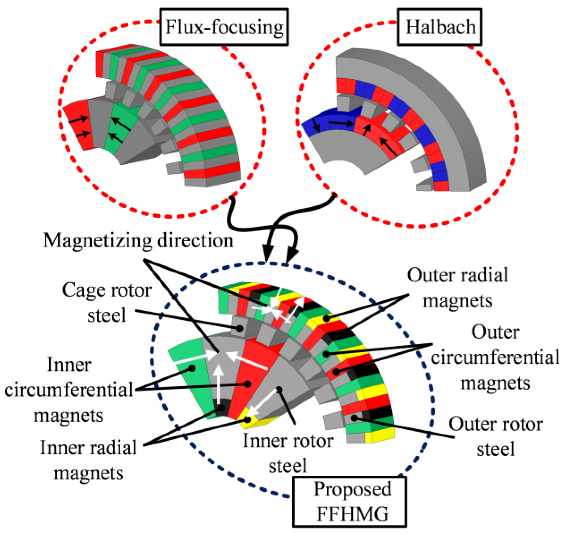
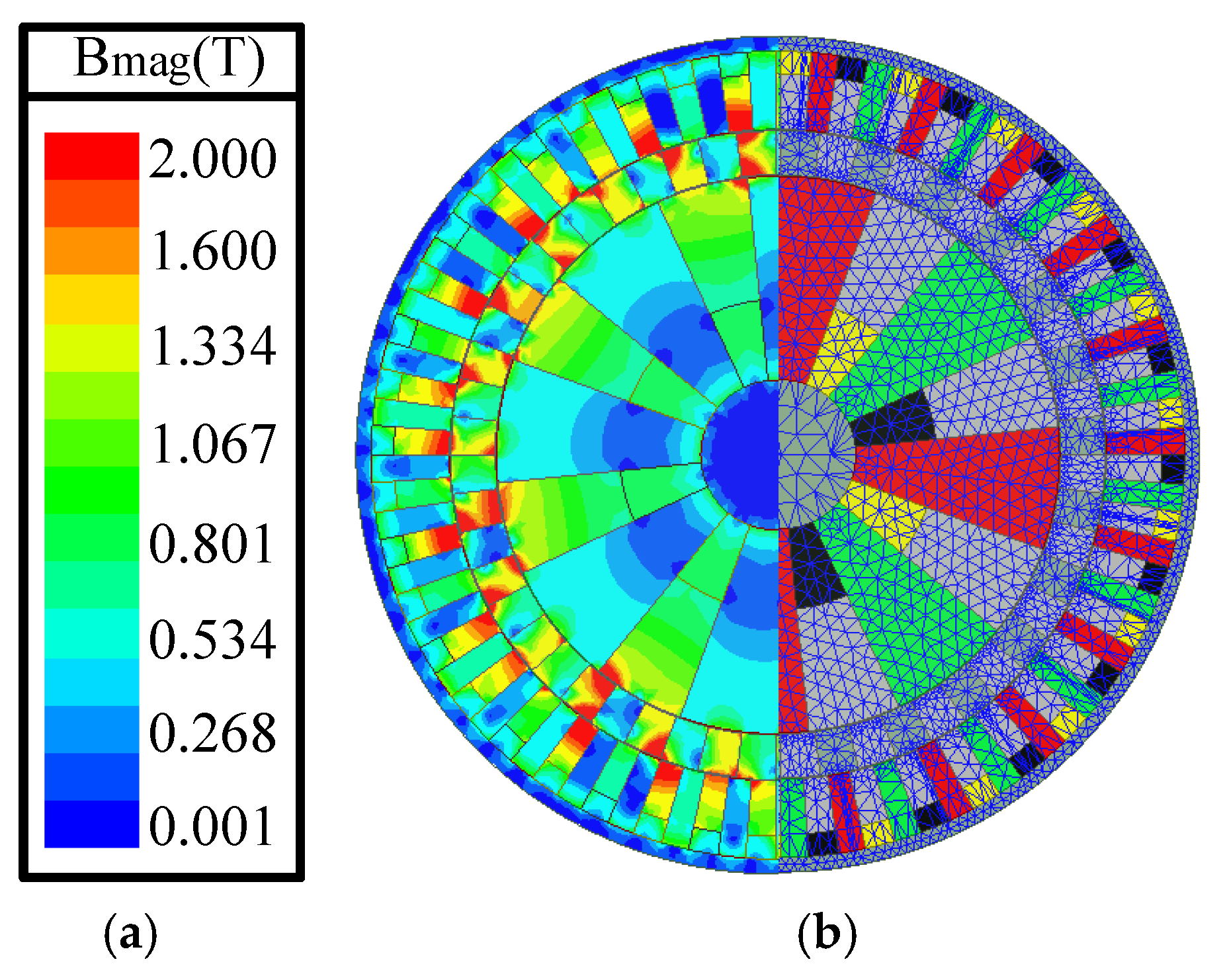
Figure 1 illustrates the structure of the proposed FFH-CMG that consists of PMs on the inner rotor, ferromagnetic pole pieces on the cage rotor, and PMs on the outer rotor. The modulation effect of the cage rotor enables effective magnetic coupling between the inner and outer rotors. As is shown, the red, green, black, and yellow magnets are producing flux lines in positive circumferential, negative circumferential, positive radial, and negative radial directions, respectively. The proposed FFH-CMG can be considered as a combination of flux-focusing and Halbach MGs, as shown in Figure 1, in which the flux-focusing PM arrangement transmits the major torque. The Halbach array contributes to the torque transmission as well; moreover, it reduces the leakage flux of the flux-focusing structure and increases the VTD of the MG accordingly. Therefore, the total output torque of the proposed FFH-CMG is larger than the sum of the output torque of flux-focusing and Halbach MGs, and a high VTD can be achieved.
The radial component of the air-gap flux density after flux modulation can be expressed as follows [30]:
B ( r , θ ) = λ 0 m = 1 ,   3 ,   5 + b m ( r )   cos [ m p ( θ Ω r t ) + m p θ 0 ] + 1 2 m = 1 ,   3 ,   5 + j = ± 1 ,   ± 3 ,   ± 5 ± λ j ( r ) b m ( r )   cos ( ( m p + j n s ) ( θ ( m p Ω r + j n s Ω s ) ( m p + j n s ) t ) + m p θ 0 ) + 1 2 m = 1 ,   3 ,   5 + j = ± 1 ,   ± 3 ,   ± 5 ± λ j ( r ) b m ( r )   cos ( ( m p j n s ) ( θ ( m p Ω r j n s Ω s ) ( m p j n s ) t ) + m p θ 0 )
where p and ns are the number of pole pairs on the PM rotor and the number of ferromagnetic pole pieces; Ωr and Ωs are the rotational velocities of the PM rotor and ferromagnetic pole pieces; m, and j are the corresponding numbers of Fourier components for the flux density and the modulating function; λj and bm are the Fourier coefficients of modulation permeance and flux density distribution of PMs; t and 
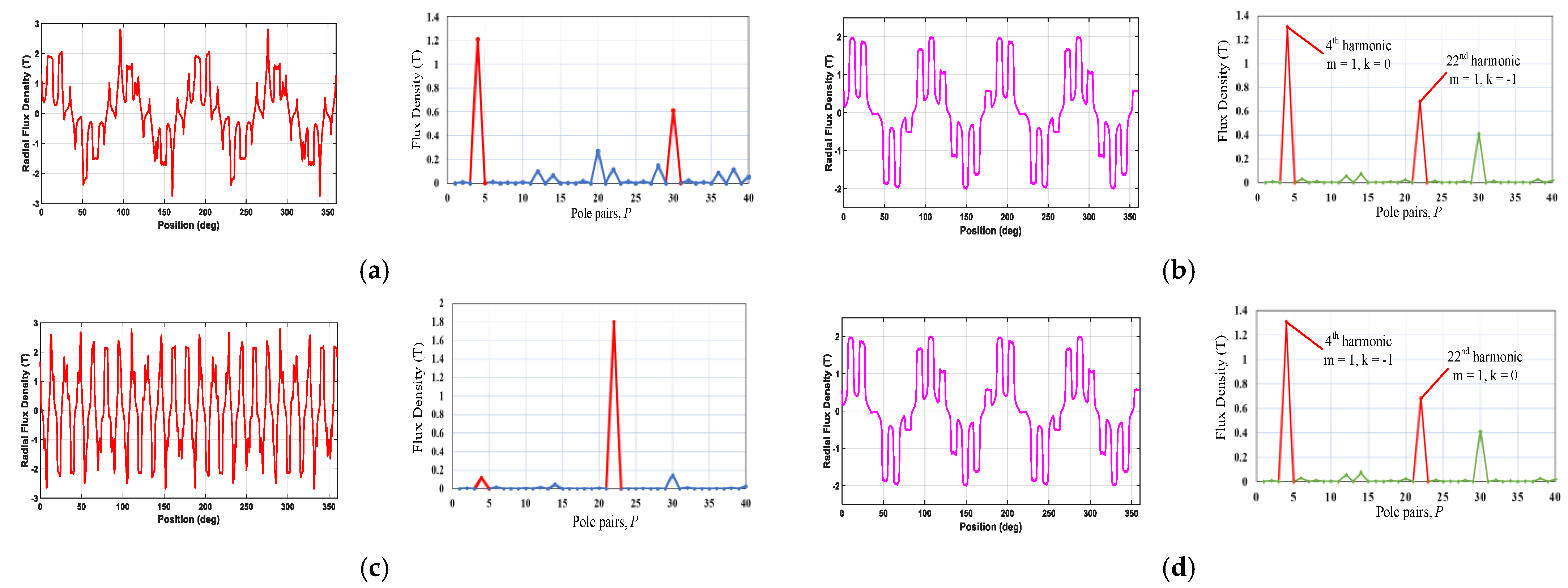
θ are the time and position of the PM rotor, respectively. According to (1), the radial flux density in the inner airgap consists of a series of spatial harmonics, as follows:
{ p m , k = | m p + k n s | m = 1 ,   3 ,   5 ,   , + k = 0 ,   ± 1 ,   ± 2 ,   ,   ±  
The corresponding angular velocity of each spatial harmonic can be obtained by:
Ω m , k = m p m p + k n s Ω r + k n s m p + k n s Ω s
To achieve the maximum torque, m = 1 and k = −1, should be met in the above equation [31]. Consequently, by holding different parts of the MG in a fixed position, different gear ratios can established. In this paper, the outer rotor of the FFH-CMG is fixed, and the cage rotor and inner rotor are considered as low-speed and high-speed rotors, respectively. Therefore, substituting Ω3 = 0, the gear ratio of the proposed FFH-CMG can be calculated as follows:
G r = n s p h
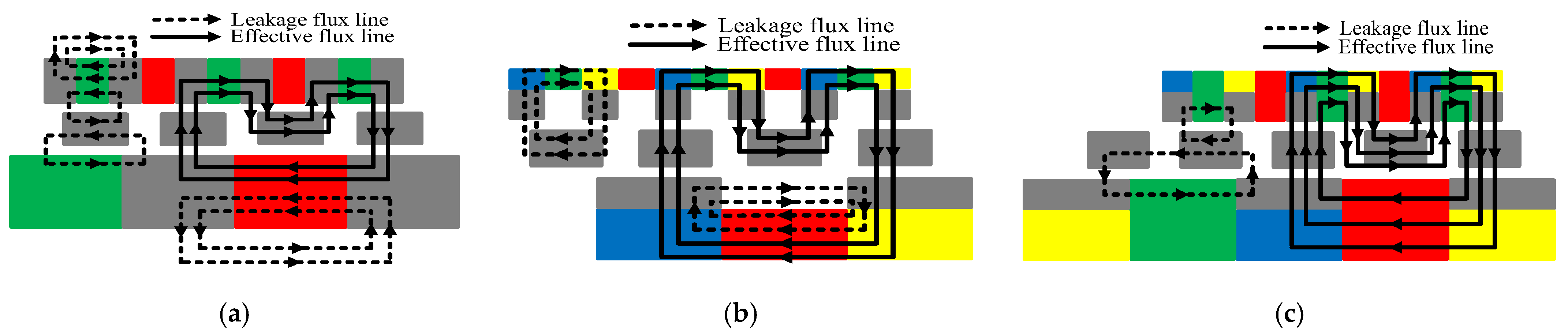
Figure 2a shows the flux lines of the flux-focusing MG. The leakage and effective flux lines are distinguished with dotted and solid lines, respectively. It is obvious that a significant portion of the interior flux lines end their path by the inner side of the high-speed rotor. This means that there will be lower flux density in the air gap and approximately half of the magnets’ fluxes do not contribute to the torque transmission. Moreover, there are some leakage fluxes that circulate between the rotors and ferromagnetic pole pieces, which have a deteriorating effect on the torque transmission and increase the core loss in the cage rotor. Implementing the Halbach array in the interior side of the high-speed rotor and the exterior side of the low-speed rotor blocks the path of leakage fluxes that were subjected to the flux-focusing structure, as illustrated in Figure 2b. However, another leakage flux pattern is revealed in this structure, which closes their route through the vacant space between the rotor’s steel segments. The above-mentioned problems can be addressed by integrating the Halbach array into the flux-focusing design, as depicted in Figure 2c. With the addition of the Halbach PM arrays, all the flux lines in the rotor cross the air gap, which will increase the torque density of the proposed FFH-CMG. The same works for the outer rotor, where all the flux lines of the outer rotor PMs are forced to pass the air gap with the help of the Halbach arrays on the outer rotor. In comparison with the basic flux-focusing topology, the deteriorating leakage fluxes in the proposed FFH-CMG are significantly reduced; nonetheless, the leakage fluxes in the cage rotor continue to exist, in spite of the fact that their effect is trivial.
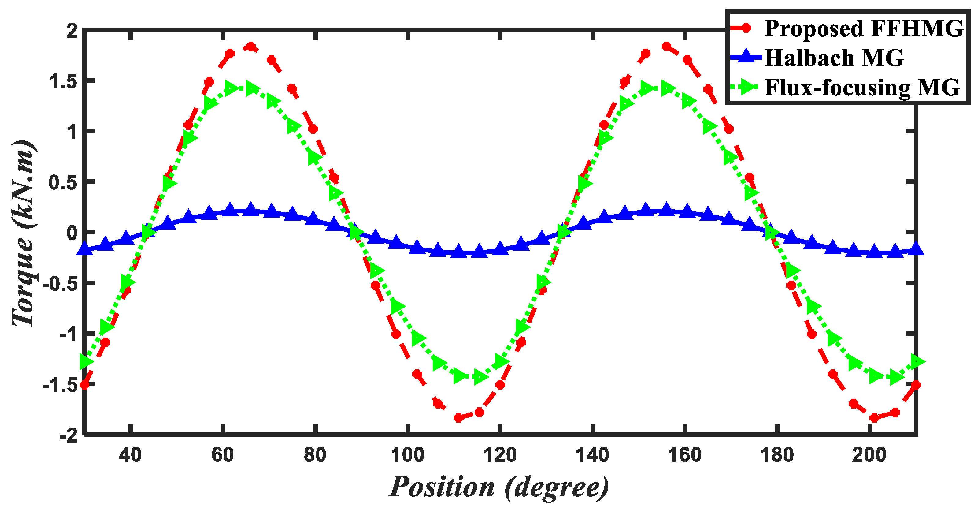
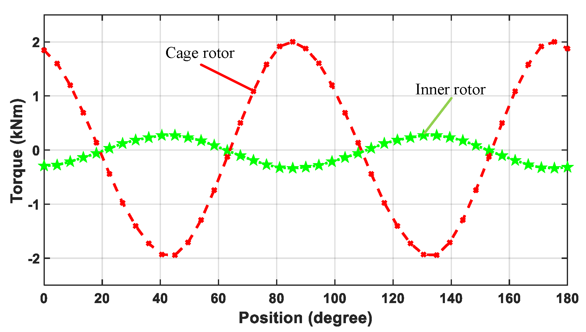
The proposed FFH-CMG is a combination of flux-focusing MG and Halbach MG, and both of them can transmit torque independently. Figure 3 shows the stand-still torque of the cage rotor of the flux-focusing MG, Halbach MG, and the proposed FFH-CMG. One can see that the maximum output torque of the flux-focusing MG, Halbach MG, and the proposed FFH-CMG are 1.4, 0.23, and 1.74 kNm, respectively. The output torque of the proposed FFH-CMG is larger than the sum of output torque of the flux-focusing MG and Halbach MG, because Halbach magnets help to reduce the leakage flux of the flux-focusing MG and increase its output accordingly.

3. Multi-Objective Design Optimization of the Proposed FFH-CMG

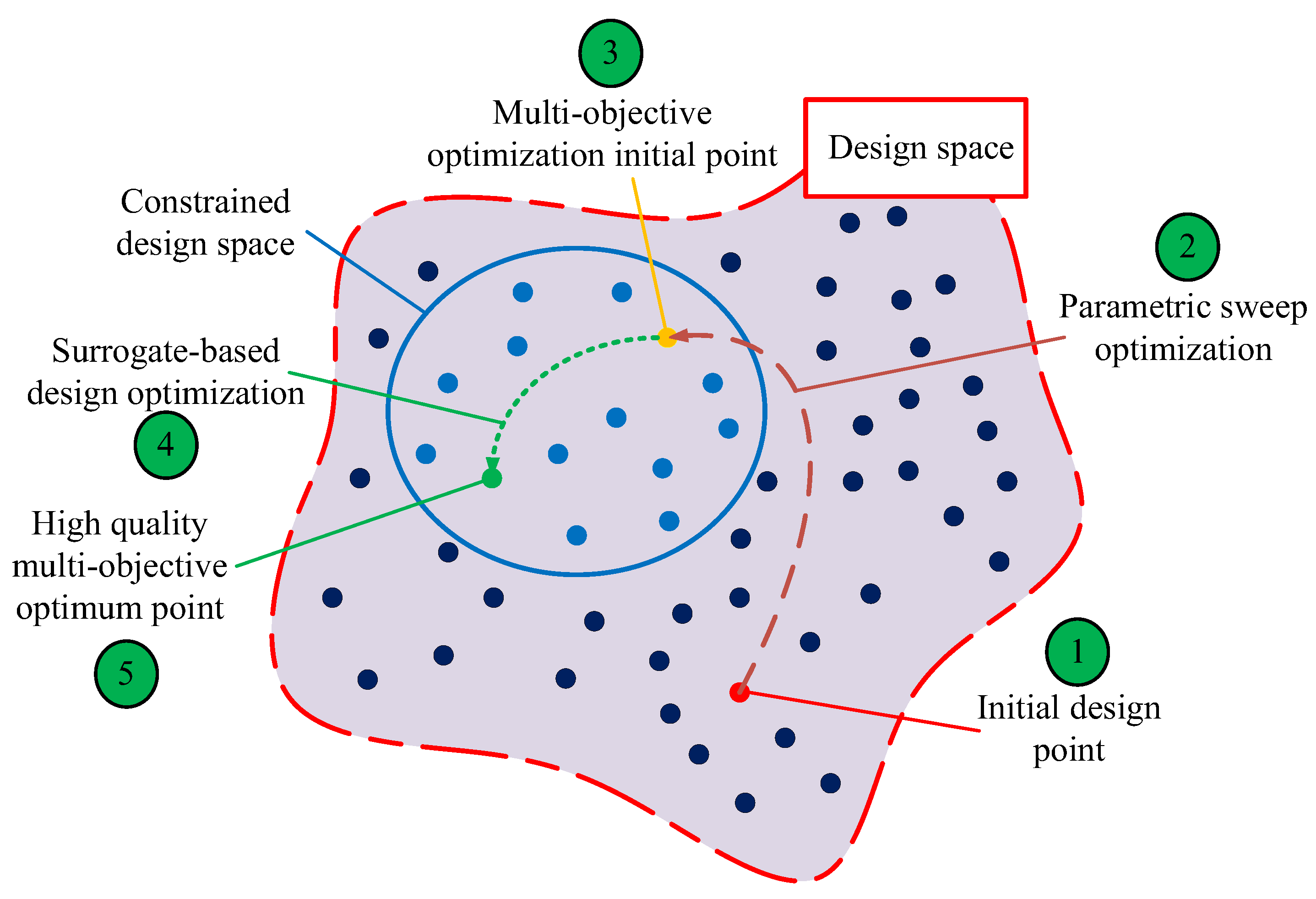
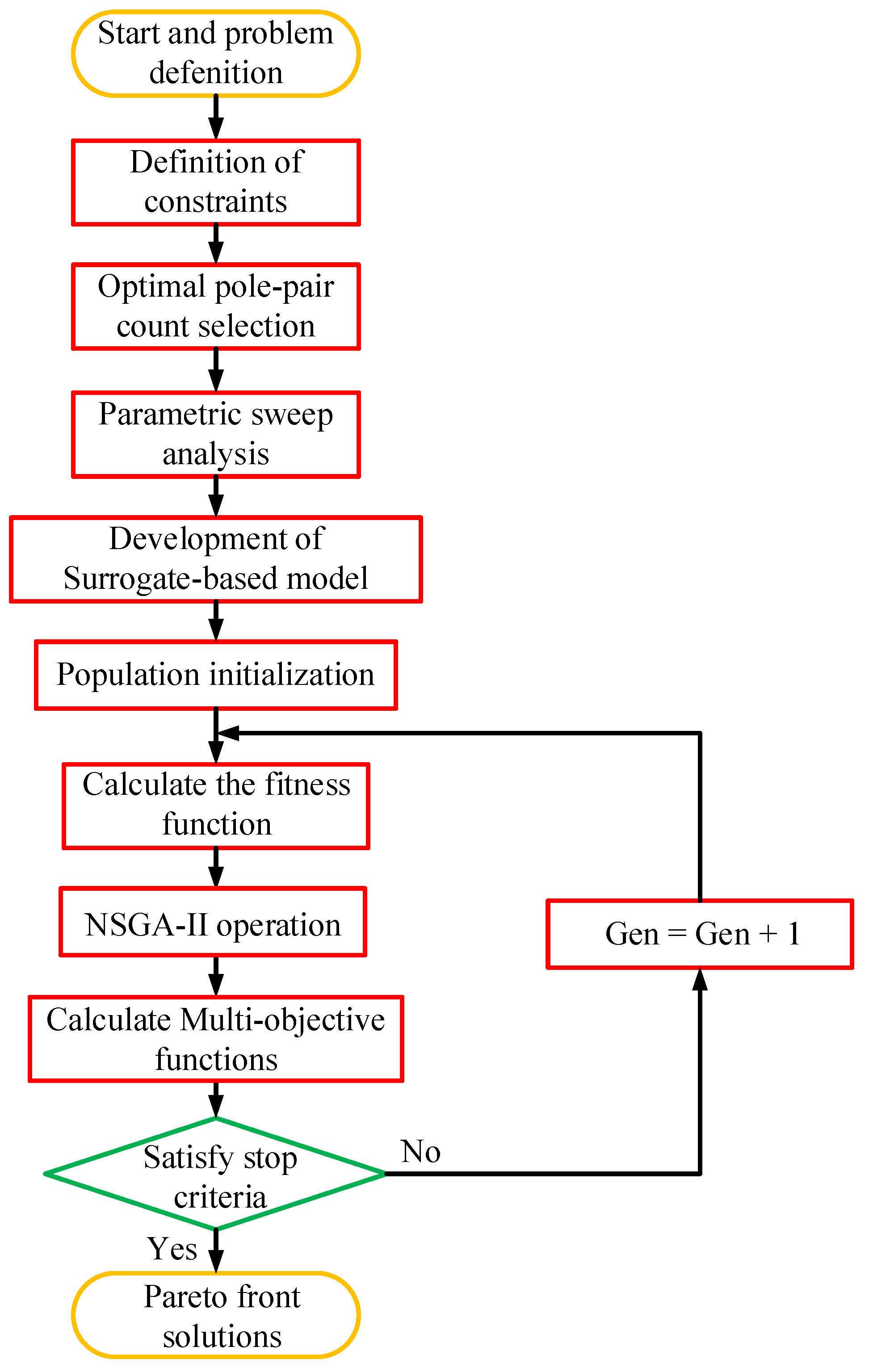
Due to their high-dimensional and multi-level geometry, the design optimization of electromagnetic devices such as MGs is not a straightforward procedure. Consequently, the traditional optimization approaches are not powerful enough to be adopted for the multi-objective optimization of MGs. In this regard, modern intelligent algorithms, coupled with FEA, can be a suitable alternative for such purposes. Nevertheless, the convergence process of the FEA-coupled approaches is quite time-consuming due to the iterative function of these algorithms, in which many sampling data are required for each iteration. Surrogate-based models, also called approximate models, can be used to replace the FEA to predict the required sampling data with an acceptable accuracy and fast speed. In this section, a surrogate-based multi-objective optimization is conducted to extract the optimal design of the FFH-CMG in terms of VTD, TPMV, efficiency, and torque ripple. The procedure of the proposed optimization algorithm is as follows: (a) the design constraints of the MG are defined according to the desired application; (b) the best pole pair combination for the proposed FFH-CMG is obtained based on a tree diagram analysis of the feasible combinations; (c) a parametric sweep optimization is then conducted to shift the initial design point to the constrained design space and obtain the suitable initial point for the subsequent intelligent optimization algorithm, as illustrated in Figure 4; (d) eventually, the surrogate model based on Kriging fitting method and LHS approach is established to predict the objective functions of the required sampling data with an acceptable exactness, and the NSGA II intelligent optimization method is implemented to obtain Pareto-front optimal solutions for the MG design. The step-by-step progress of the proposed optimization method is summarized in the brief flowchart depicted in Figure 5.

3.1. Design Constraints

In an optimization case, a set of constraints is usually defined to confine the searching space to the feasible and desirable solutions. From the perspective of the desired application and the fabrication complexity, the optimization constraints of the proposed FFH-CMG are summarized as follows:
  • 6 ≤ Gr ≤ 7: In order to generate enough torque to propel the EV, the gear ratio is normally between 6 and 10 in EV applications. Since a large gear ratio will increase the leakage flux, a gear ratio between 6 and 7 is targeted in our design.
  • η ≥ 90%: The proposed FFH-CMG will be axially coupled with an electric motor (EM). A minimum efficiency of 90% is set as another constraint in our design to guarantee the high overall efficiency of the electric drive system.
  • wpm ≥ 3 mm: A very small size of magnets increases the complexity of the device and the magnetizing process. Consequently, the PM width (wpm) is set to be larger than 3 mm in our design.
  • Ro ≤ 135 mm, and Ri ≥ 25 mm: Due to the limited space in an EV, the maximum radius of MG is set to be Ro = 135 mm. Meanwhile, a common shaft is adopted to axially couple the inner rotor of the MG with the motor rotor. Hence, a minimum inner radius of Ri = 25 mm is considered for the shaft installation.

3.2. Optimal Pole Pair Combination

According to the required torque-speed levels of the considered application for the proposed FFH-CMG, a gear ratio of around 6 could be a suitable choice. To ensure the minimum torque ripple and noise, a non-integer gear ratio should be selected [32]. Furthermore, the number of ferromagnetic pole pieces in the cage rotor should be even to avoid detrimental, unbalanced radial forces being found in the modulation ring [33]. Since the topology of the proposed FFH-CMG is mainly based on the flux-concentrating structure, the number of pole pairs in the high-speed rotor must be more than ph = 2, to guarantee the conduction of flux lines to the air gap.
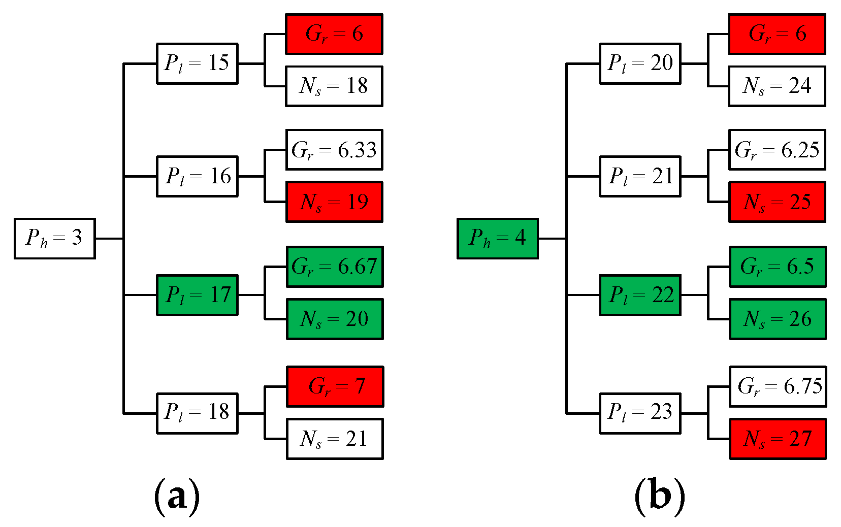
Consequently, a pole-pair-count selection analysis was conducted using a tree diagram, as demonstrated in Figure 6. The evaluation of more than four pole pairs in the high-speed rotor is avoided in the suggested tree diagram due to the high manufactural complexity that will result from the high number of pole pairs in the low-speed rotor. As illustrated, two potential optimal solutions can be employed with ph = 3, and ph = 4 pole pair numbers of high-speed rotors, which led to Gr = 6.67, and Gr = 6.5 gear ratios, respectively. In order to select the best pole pair combination for the reported optimal solutions, a 2D-FEA was conducted to evaluate the maximum torque and torque ripple of the proposed FFH-CMG in each feasible combination. The obtained results are summarized in Table 1. According to the acquired data, in the case of ph = 4, a larger stall torque and a lower output torque ripple is achieved. Hence, the best pole pair combination of the proposed FFH-CMG was selected to be ph = 4, pl = 22, and ns = 26.

3.3. Parametric Sweep Optimization

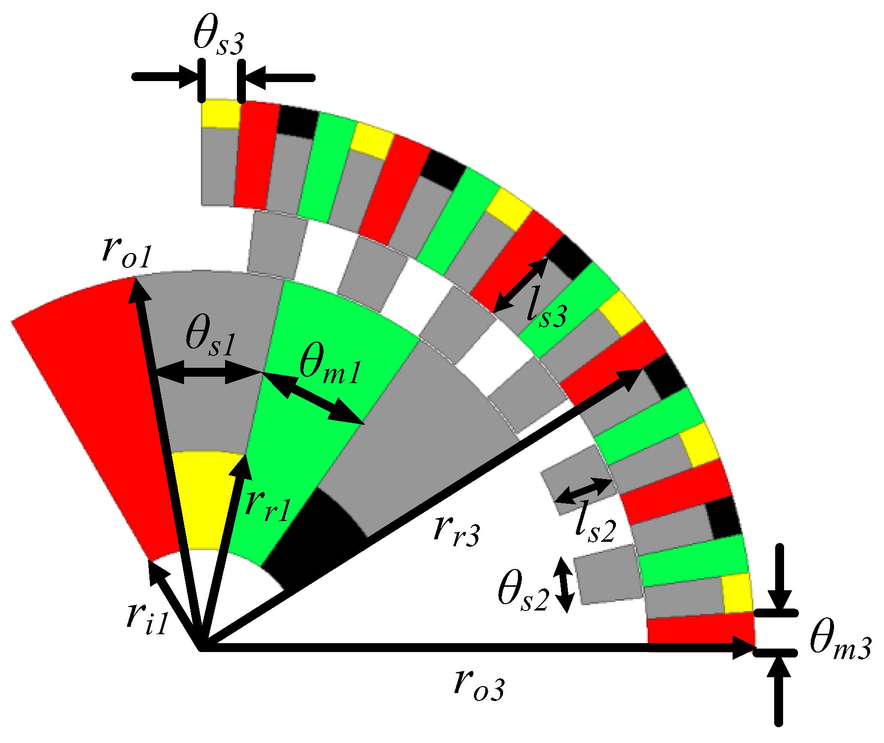
To achieve the highest TPMV and select the best initial design for the multi-objective optimization of the proposed FFH-CMG, a single-objective optimization, based on the parametric sweep method, was performed. In Figure 7, the geometric parameters of the proposed MG are depicted. As shown, θs1, θm1, θs3, and θm3 are the spans of the inner rotor steel, inner rotor magnet, outer rotor steel, and outer rotor magnets, respectively. The inner radius of the high-speed rotor (ri1 = 25 mm) and the outer radius of the low-speed rotor (ro3 = 135 mm) are fixed during the optimization to ensure that the total volume of the FFH-CMG remains constant.
Initially, a parametric sweep was performed for the length (ls2) and bar span (θs2) of the cage rotor. During the parametric sweep, the total volume and the air-gap length of the FFH-CMG were fixed. In other words, with the increase in ls2, the values of ro1, and ls3 are decreased in the same proportion to keep the volume constant.
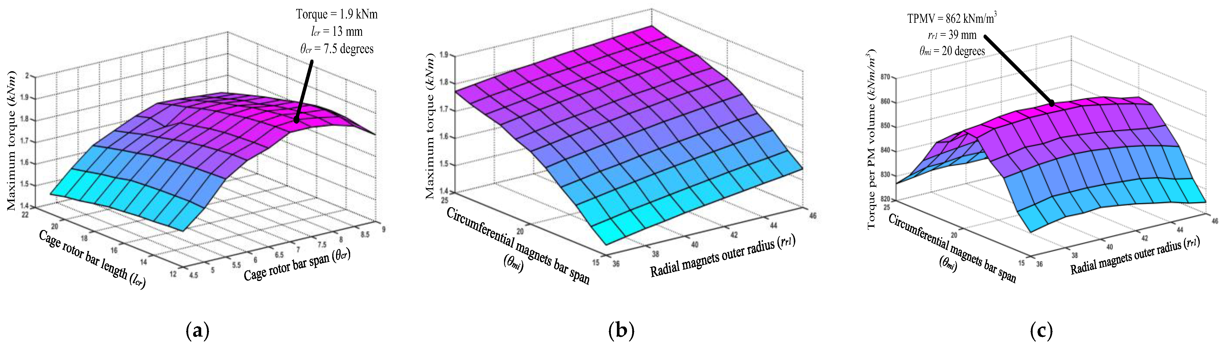
In Figure 8a, the obtained results of the parametric sweep using 2D-FEA are illustrated. It can be noticed that a maximum stall torque of 1.9 kNm can be achieved when θs2 and ls2 are 7.5 degrees and 13 mm, respectively. Another parametric sweep is provided to select the most optimal thickness values of interior radial magnets (rr1) and the bar span of the circumferential magnets (θm1). In Figure 8b, the stall torque values of the FFH-CMG are depicted for the different values of rr1 and θm1. It can be observed that the maximum torque of the FFH-CMG increases with the increase in of rr1 and θm1 values because of the increase in PM volumes. However, this will increase the total cost of the FFH-CMG. Hence, the optimal values of rr1 and θm1 are obtained when they lead to the highest TPMV. Figure 8c demonstrates the influence of the magnet thickness and circumferential span on the TPMV. A maximum TPMV of 862 kNm/m3 is obtained when rr1 and θm1 are 39 mm and 20 degrees, respectively. The final geometric parameters of the proposed FFH-CMG are summarized in Table 2. The obtained values will be used as the initial design for the surrogate-based multi-objective optimization in the following.

3.4. Surrogate-Based Multi-Objective Design Optimization

By finishing the parametric sweep optimization, a proper value was obtained for each of the design variables. However, it is necessary to conduct a local compressive search around the obtained point to ensure the reliability of the optimization process. To achieve this goal, a non-dominated sorting genetic algorithm (NSGAII), coupled with a surrogate modeling technique, was adopted to efficiently search the constrained design space. The Kriging modeling method was utilized as the surrogate-model construction tool due to its high accuracy and low training cost compared to conventional methods such as response surface methodology (RSM) or artificial-intelligence-based methods such as artificial neural networks (ANNs) [34,35]. The Kriging surrogate model is defined as follows:
y ( x ) = β ( x ) + Z ( x )
where β ( x ) can be the linear of the quadratic polynomial and Z ( x ) is the random error term. A detailed mathematical definition of the Kriging model can be found in [36].
To train an accurate surrogate model for each optimization objective, it is necessary to create a reliable training dataset. The number of samples and their distribution in the design space are two major factors that can significantly affect the accuracy and required computational cost.
The LHS method has proven to be an efficient sampling technique that can provide uniformly distributed samples in the design space. In this way, it is possible to increase the accuracy of the models based on a fixed number of samples. In this study, the number of input variables for the optimization process is equal to six (see Table 3). Therefore, 270 (2.5423 levels for each input variable) samples were generated to properly cover the design space. By using the developed training dataset, a surrogate model of each optimization objective was constructed. The R-squared ( R 2 ) accuracy metric was used to measure the accuracy of the constructed surrogate models, and the measured values demonstrate an acceptable match between the FEA results and the values predicted by the surrogate models.
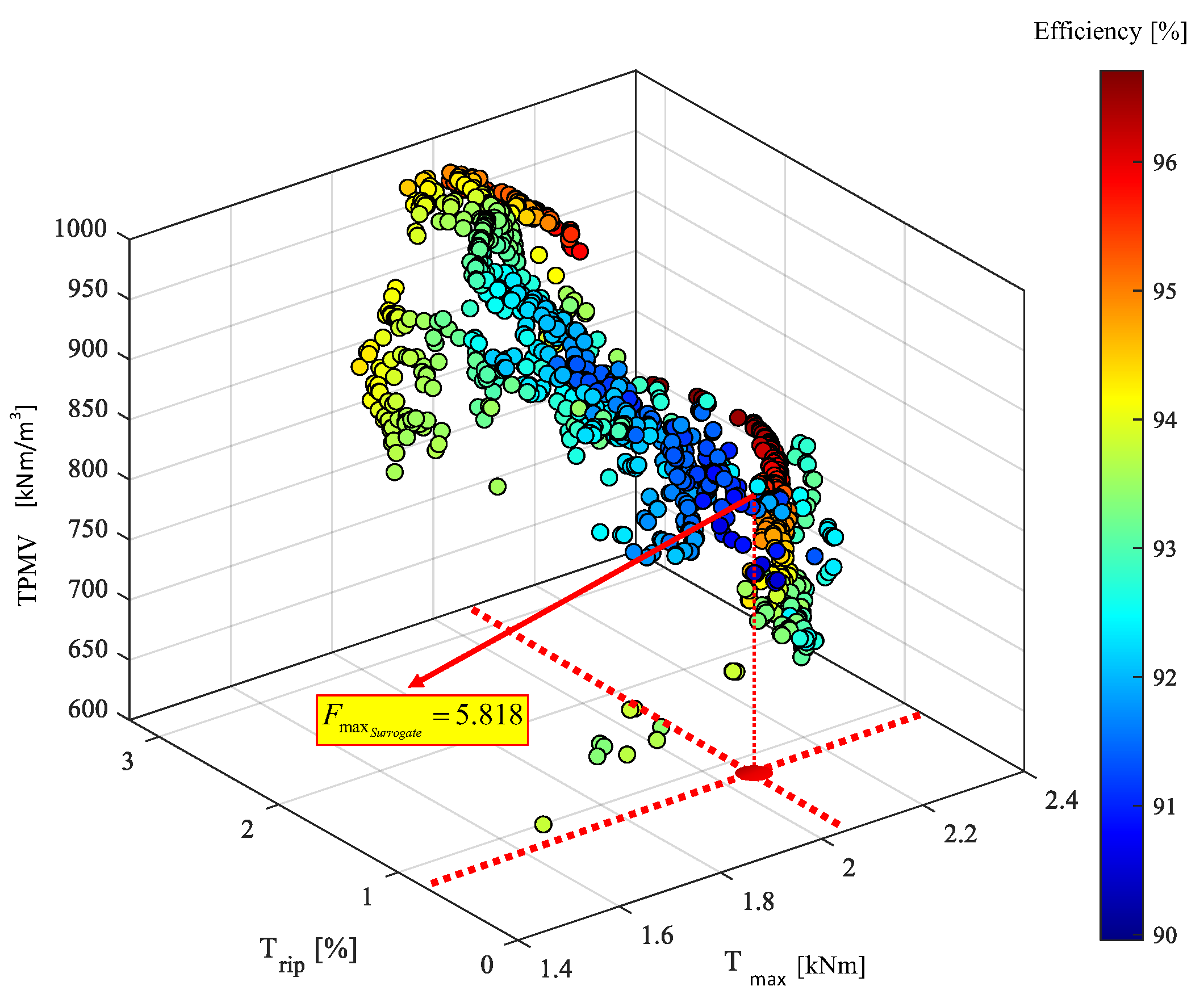
By adopting the NSGAII, 10,000 samples (100 population size and 100 generations) were evaluated during the multi-objective optimization process. From the evaluated designs, 2057 Pareto-optimum solutions were achieved that cannot be dominated by any other design. Figure 9 illustrates the obtained Pareto front with respect to all four objective functions. While T r i p varies within a small range, the remaining three objectives, including Tmax, TPMV, and η, considerably change between the obtained Pareto solutions. Figure 10 also shows the normalized distribution of the design parameters according to the Pareto solutions. While parameters such as ls2 and rr3 generate the optimum design with the values near to their upper bound (near to one in normalized plots), the θm3 provides most of the optimum designs with the values near to its lower and upper bound.
The diversity of the Pareto-optimum solutions demonstrates that a successful multi-objective optimization was achieved. However, a solution must be chosen as the final product of the process. To select the final solution, a decision-making function considering all the optimization objectives was defined as follows:
F = T m a x o p t i m u m T m a x i n i t i a l + T P M V o p t i m u m T P M V i n i t i a l + T r i p i n i t i a l T r i p o p t i m u m + η o p t i m u m η i n i t i a l
where the aim is to find the maximized value among the obtained Pareto solutions. Figure 9 illustrates the position of the selected optimum design corresponding to the objectives, and the optimized parameters are presented in Table 3. Note that the predicted performance is only a surrogate-based solution. Therefore, its performance must be re-evaluated using the FEA method. The performance evaluation and comparison results are presented in the next section.

3.5. Effectiveness of the Proposed Optimization Approach

Unlike the conventional surrogate-based optimization algorithms that were employed by researchers in previous works, the proposed approach benefits from two main advantages: (1) the number of samples that are required to establish a precise surrogate model is reduced, and (2) the output results of the proposed optimization method are more reliable, and can be considered as the global optimum point. In the following, each advantage of the proposed technique is elaborated.

3.5.1. Sampling Efficiency

The initial design space of an MG, as well as other electromagnetic devices, is always a large enough to cover all possible design schemes. However, the optimal solution is only located in a small subspace. If this aspect is disregarded, a significant number of samples that lie outside the relevant subspace will undergo evaluation during the optimization process, leading to an unnecessary waste of computational resources. A sequential parametric sweep optimization was developed in this paper to confine the design space to an interesting subspace. This technique empowers designers to attain a precise surrogate model using the lowest possible number of sampled data points.
After the construction of approximate models, the accuracy and effectiveness of the constructed models should be verified with some new samples. The verification method implemented in this paper is the coefficient of determination R2, defined as:
R 2 = 1 i = 1 N e ( y i y ^ i ) 2 i = 1 N e ( y i y i ¯ ) 2
where Ne is the number of new samples {xi}; yi is their true responses; y ^ i , and y i ¯ are the fitting approximate responses and their average value. This is a numerical value that represents the degree of compatibility between the data and a particular model, which is often represented by a line or curve. This value serves as one of the metrics used to assess the accuracy of approximate models. A higher accuracy is indicated when the R2 value approaches 1.
Using the defined accuracy metric, a comparison between two optimization cases is conducted to demonstrate the effectiveness of the proposed surrogate model, coupled with the parametric weep technique. In both cases, the same number of samples was utilized to establish the approximate model. In the proposed approach, 200 samples were employed to find a suitable initial point for the subsequent multi-objective optimization, and then 300 samples were employed, using the LHS method, to establish the surrogate model. A total of 500 samples was utilized in the proposed method. For the second case, 500 samples, using the LHS method, were employed to establish the conventional surrogate model in the initial design space. Table 4 illustrates the calculated R2 values for each method. One can see that the accuracy of the proposed optimization approach is much better than that of the conventional surrogate-based optimization methods. This characteristic is more noteworthy when the objectives of the optimization problem are very sensitive to the optimization parameters, like the torque ripple in this case. The obtained results demonstrate the superiority of the proposed approach as compared to conventional surrogate-based optimization methods. More than 1000 samples with true responses are required for the conventional surrogate-based method to achieve an approximate model as accurate as the one established by the proposed approach. For the proposed FFH-CMG, each 2D-FEA takes an average time of 2 min. This means that for an approximate model using conventional surrogate-based optimization to achieve the same accuracy as the proposed optimization method, 1000 min (16.7 h) more time is needed to extract the required samples. This time duration could be even more considerable for topologies that require 3D-FEA.

3.5.2. Optimization Reliability

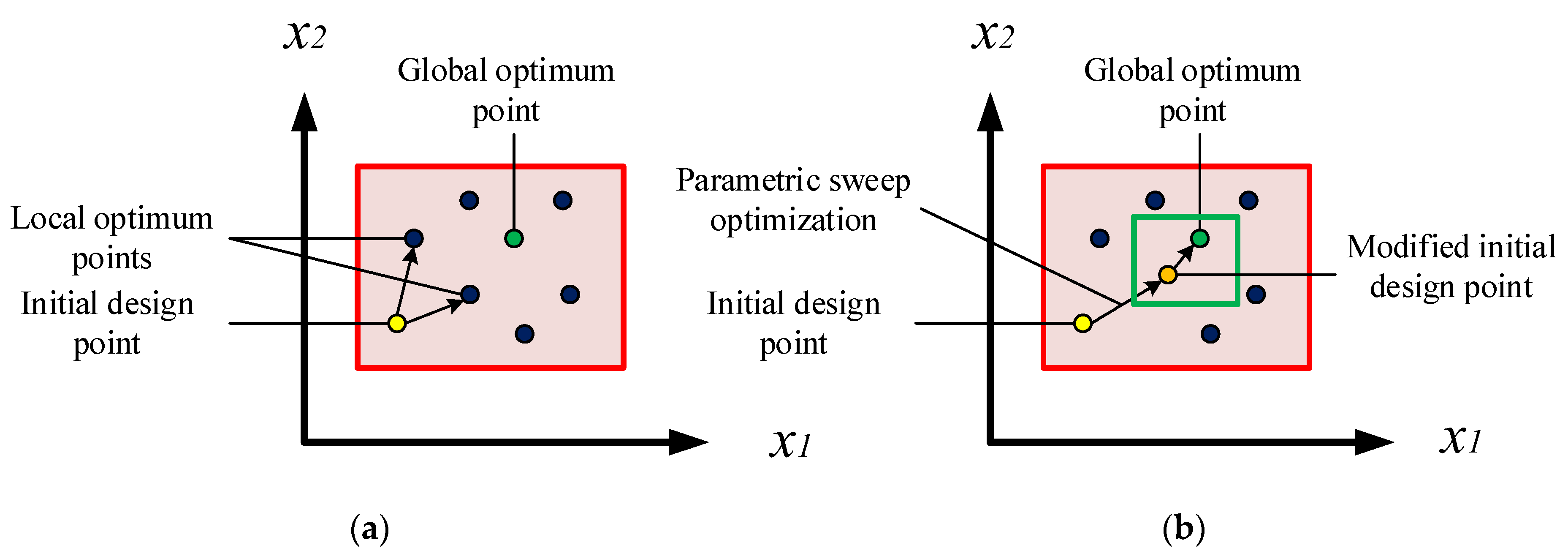
In the initial design space of an MG, there could be several local optimum points. Therefore, there is always a risk of convergence to the local optimum points rather than the global points during the optimization process, as illustrated in Figure 11a. The proper selection of the initial sampling point is the key element when avoiding this problem. Thanks to the pre-conducted parametric sweep optimization that was used to select the suitable initial point for the subsequent multi-objective optimization, the probability of local optimum results being achieved was significantly reduced and the obtained results can be considered the global optimum design points, as illustrated in Figure 11b.

4. Performance Comparison and FEA Re-Evaluation of the Optimization Results

The working principle of the proposed FFH-CMG has been described, and a surrogate-based multi-objective optimization was conducted to obtain the optimal design parameter values to improve the performance of the MG. In order to verify the performance of the designed structure, a simulation model of the optimized FFH-CMG, using the parameters given in Table 3, was established using Ansys Maxwell (2021 R1), and the electromagnetic performance was investigated through FEA.

4.1. Radial Flux Density Distribution

To clearly exhibit the modulation effect in the proposed FFH-CMG, the waveforms and harmonic spectra of the radial flux density distribution in the inner and outer airgaps are demonstrated in Figure 12. Firstly, the PMs on the low-speed rotor are removed and replaced with rotor yoke steels so that only the modulation effect of the cage rotor on the magnetic field produced by high-speed rotor PMs is investigated. As illustrated in Figure 12a, the flux density in the inner air-gap has the dominant 4th harmonic due to the number of pole pairs in the high-speed rotor and, after passing through ferromagnetic pole pieces and the implementation of the modulation effect, the 4th and 22nd harmonics will be the most dominant components in the outer air gap, as shown in Figure 12b. Secondly, the PMs on the high-speed rotor are removed and replaced with rotor yoke steels so that only the modulation effect of the cage rotor on the magnetic field produced by low-speed rotor PMs is investigated. As illustrated in Figure 12c, the flux density in the outer air gap has the dominant 22nd harmonic due to the number of pole pairs in the low-speed rotor, and after passing through ferromagnetic pole pieces and the implementation of the modulation effect, the 4th and 22nd harmonics will be the most dominant components in the inner air gap, as shown in Figure 12d. The waveforms of the modulated flux distribution of high-speed and low-speed rotor PMs are quite similar, as illustrated in Figure 12b,d, which confirms the correct performance of the modulation technique. Consequently, the most effective components are generated by considering the combination of m = 1 and k = −1 in (2), which contribute to the torque transmission in the proposed FFH-CMG.
The mesh plot and the magnitude of flux density are illustrated in Figure 13. It can be observed that the edges of the cage rotor segments are slightly saturated. This saturation can be suppressed by increasing the cage rotor bar span (θs2); however, this sacrifices the modulating effect of the cage rotor and reduces the output torque.

4.2. Torque Capability Analysis

The stand-still torque waveforms of the inner high-speed rotor and the cage rotor when the outer rotor is fixed are illustrated in Figure 14. During this simulation, the cage rotor is locked while the high-speed rotor rotates at 3000 rpm. One can see that a maximum output torque of 2 kNm is obtained when the inner rotor’s position is 85.5 degrees. Considering the outer radius and the total stack length of the MG given in Table 2, the VTD of the proposed FFH-CMG is 411.22 kNm/m3 and the TPMV is 829.8 kNm/m3; both of these results are significantly larger than those of existing MG counterparts. Figure 15 shows the steady-state torque waveforms when the high-speed rotor and the cage rotor rotate at 3000 rpm and 460 rpm, respectively, during which the negative torque of the inner rotor indicates a torque in the opposite direction. During this simulation, the initial position of the high-speed rotor is set to be 85.5 degrees to reach the maximum torque. The torque ripples of the high-speed and cage rotors are 2.32% and 0.54% of the average torque values, respectively.

4.3. Effect of Modulation Ring Bridge

The effect of the connection bridge on the different features is investigated in the revised manuscript to evaluate the three possible configurations of the modulation ring. Table 5 illustrates the variation in the output torque, torque ripple, and the iron losses in the proposed magnetic gear, considering the connection bridge with a thickness of 1 mm in three different positions.
According to Table 5, the inner bridge achieves the best performance when compared to the central or outer bridge solution concerning average torque and torque ripple; however, the iron losses are higher than the other two cases.

4.4. Performance Comparison of Design Models

As previously mentioned, the eventual aim of the multi-objective optimization that was conducted is to find the maximized value of the objective function (F) among the Pareto-front solutions. The obtained normalized values of F in each design step are summarized in Table 6, in which the convergence progress of the optimization to the most optimal design point is illustrated. One can see that the objectives obtained through the 2D-FEA have a trivial discrepancy with the surrogate-based results. This accordance validates the good accuracy of the established surrogate model of the proposed FFH-CMG during the optimization process. Furthermore, as reported in Table 6, the values of Tmax, TPMV, and η in both the parametric sweep and multi-objective steps are increased as compared to the initial design, and Trip is significantly reduced to improve the torque performance of the MG. A notable point in this comparison is that the TPMV resulting from the parametric sweep optimization is larger than that obtained using the surrogate-based method. This is quite reasonable, since the former is a single-objective optimization aiming to maximize the value of TPMV, while the latter is a multi-objective optimization that investigates the performance of the MG from different perspectives and aims to obtain the optimal design regarding four different objectives. Consequently, the TPMV obtained using the surrogate-based design is slightly lower than that obtained using the parametric sweep design, while the other three objectives are considerably improved.
The comparative data of three topologies with the same size parameters, obtained using this optimization approach, are collected in Table 7. One can see that Tmax of the proposed FFH-CMG is higher than the sum of the flux-focusing and Halbach structures. This feature demonstrates the flux-leakage-mitigation ability of the proposed topology, resulting in a higher VTD and TPMV. The torque ripple (Trip) of the optimized proposed structure is lower than those of flux-focusing and Halbach configurations. This fact stems from the effectiveness of the multi-objective optimization method that was implemented. As shown in Table 7, the Halbach structure has the highest efficiency among the analyzed structures. This was predictable due to the lower iron losses and magnet eddy current losses found in this structure. On the other hand, flux-focusing configuration has the advantage of a higher VTD, but its efficiency is lower due to the flux leakage in the iron yoke. The proposed FFH-CMG takes the advantages of both structures to provide a high VTD and TPMV, as well as a good efficiency level, due to the utilization of the Halbach array to block the leakage flux path in the conventional flux-focusing structure.

5. Conclusions

This paper proposes a new flux-focusing MG combined with Halbach PM arrays for EV applications. The Halbach PMs not only generate additional torque, but also reduce the leakage flux of flux-focusing PMs, which further increases the torque density. A surrogate model was artfully integrated into the multi-objective optimization algorithm, and the proposed MG shows an optimized torque performance and high efficiency. Compared with the traditional, surrogate-based, optimization approach, the proposed multi-objective approach, coupled with the parametric sweep method, is less time-consuming and requires fewer samples to achieve an acceptable accuracy level. The performance of the optimized MG was re-evaluated through 2D simulations, and the results showed that the proposed MG can achieve a torque density of 411 kNm/m3 and an efficiency higher than 93%.

Author Contributions

Conceptualization, A.S.; Software, F.F.-R.; Validation, A.S.; Formal analysis, F.F.-R.; Resources, A.S.; Writing—original draft, A.S.; Supervision, Q.W.; Project administration, Q.W. All authors have read and agreed to the published version of the manuscript.

Funding

This research was funded by Natural Sciences and Engineering Council of Canada (NSERC).

Data Availability Statement

Data are contained within the article.

Conflicts of Interest

The authors declare no conflict of interest.

References

  1. Shi, L.; Jing, J.; Wang, W.; Liu, Z.; Li, F. Electromagnetic characteristic analysis of a negative-salient hybrid permanent magnet motor for electric vehicles. IEEE J. Emerg. Sel. Top. Ind. Electron. 2023, 1–9. [Google Scholar] [CrossRef]
  2. Faradonbeh, V.Z.; Rahideh, A.; Amiri, E. Analytical modeling of steel shielding cylinder in surface mounted permanent magnet machines. IEEE J. Emerg. Sel. Top. Ind. Electron. 2023, 1–13. [Google Scholar] [CrossRef]
  3. Wang, Y.; Filippini, M.; Bianchi, N.; Alotto, P. A review on magnetic gears: Topologies, computational models, and design aspects. IEEE Trans. Ind. Appl. 2019, 55, 4557–4566. [Google Scholar] [CrossRef]
  4. Aloeyi, E.F.; Shoaei, A.; Wang, Q. A hybrid coaxial magnetic gear using flux-focusing halbach permanent magnet arrangement. In Proceedings of the 2023 IEEE 14th International Conference on Power Electronics and Drive Systems (PEDS), Montreal, QC, Canada, 7–10 August 2023. [Google Scholar]
  5. Wang, S.; Zhang, J. Analysis of torque capability for permanent magnet machines with magnetic gear effect. IEEE J. Emerg. Sel. Top. Ind. Electron. 2023, 4, 1303–1312. [Google Scholar] [CrossRef]
  6. Shoaei, A.; Wang, Q. A comprehensive review of concentric magnetic gears. IEEE Trans. Transp. Electrif. 2023, 1. [Google Scholar] [CrossRef]
  7. Chau, K.T. Electric Vehicle Machines and Drives: Design, Analysis and Application; John Wiley & Sons Singapore: Singapore, 2015. [Google Scholar]
  8. Atallah, K.; Howe, D. A novel high-performance magnetic gear. IEEE Trans. Magn. 2001, 37, 2844–2846. [Google Scholar] [CrossRef]
  9. Atallah, K.; Calverley, S.D.; Howe, D. Design, analysis and realisation of a high-performance magnetic gear. IEE Proc.—Electr. Power Appl. 2004, 151, 135–143. [Google Scholar] [CrossRef]
  10. Rasmussen, P.O.; Andersen, T.O.; Joergensen, F.T.; Nielsen, O. Development of a high performance magnetic gear. In Proceedings of the 38th IAS Annual Meeting on Conference Record of the Industry Applications Conference, Salt Lake City, UT, USA, 12–16 October 2003. [Google Scholar]
  11. Al-Qarni, A.; Wu, F.; Ei-Refaie, A. High-torque-density low-cost magnetic gear utilizing hybrid magnets and Advanced Materials. In Proceedings of the 2019 IEEE International Electric Machines & Drives Conference (IEMDC), San Diego, CA, USA, 15 May 2019. [Google Scholar]
  12. Uppalapati, K.K.; Bomela, W.B.; Bird, J.Z.; Calvin, M.D.; Wright, J.D. Experimental evaluation of low-speed flux-focusing magnetic gearboxes. IEEE Trans. Ind. Appl. 2014, 50, 3637–3643. [Google Scholar] [CrossRef]
  13. Uppalapati, K.K.; Calvin, M.D.; Wright, J.D.; Pitchard, J.; Williams, W.B.; Bird, J.Z. A magnetic gearbox with an active region torque density of 239 nm/L. IEEE Trans. Ind. Appl. 2018, 54, 1331–1338. [Google Scholar] [CrossRef]
  14. Jing, L.; Gong, J.; Huang, Z.; Ben, T.; Huang, Y. A new structure for the magnetic gear. IEEE Access 2019, 7, 75550–75555. [Google Scholar] [CrossRef]
  15. Jian, L.; Chau, K.T. A coaxial magnetic gear with halbach permanent-magnet arrays. IEEE Trans. Energy Convers. 2010, 25, 319–328. [Google Scholar] [CrossRef]
  16. Wong, H.Y.; Baninajar, H.; Dechant, B.W.; Southwick, P.; Bird, J.Z. Experimentally Testing a Halbach Rotor Coaxial Magnetic Gear With 279 Nm/L Torque Density. IEEE Trans. Energy Convers. 2022, 38, 507–518. [Google Scholar] [CrossRef]
  17. Li, K.; Modaresahmadi, S.; Williams, W.B.; Wright, J.D.; Som, D.; Bird, J.Z. Designing and experimentally testing a magnetic gearbox for a wind turbine demonstrator. IEEE Trans. Ind. Appl. 2019, 55, 3522–3533. [Google Scholar] [CrossRef]
  18. Li, K.; Modaresahmadi, S.; Williams, W.B.; Bird, J.Z.; Wright, J.D.; Barnett, D. Electromagnetic analysis and experimental testing of a flux focusing wind turbine magnetic gearbox. IEEE Trans. Energy Convers. 2019, 34, 1512–1521. [Google Scholar] [CrossRef]
  19. Praslicka, B.; Gardner, M.C.; Johnson, M.; Toliyat, H.A. Review and analysis of coaxial magnetic gear pole pair count selection effects. IEEE J. Emerg. Sel. Top. Power Electron. 2021, 10, 1813–1822. [Google Scholar] [CrossRef]
  20. Halim, M.F.; Sulaiman, E.; Aziz, R.; Othman, R.N.; Rahman, A.A. Torque density design optimization of rotating pole piece concentric magnetic gear. Arab. J. Sci. Eng. 2021, 47, 2797–2806. [Google Scholar] [CrossRef]
  21. Afsari Kashani, S.A. Design and optimization of coaxial reluctance magnetic gear with different rotor topologies. IEEE Trans. Ind. Electron. 2022, 69, 101–109. [Google Scholar] [CrossRef]
  22. dos Santos Coelho, L.; Alotto, P. Multiobjective electromagnetic optimization based on a nondominated sorting genetic approach with a chaotic crossover operator. IEEE Trans. Magn. 2008, 44, 1078–1081. [Google Scholar] [CrossRef]
  23. Farshbaf Roomi, F.; Vahedi, A.; Mirnikjoo, S. Multi-objective optimization of permanent magnet synchronous motor based on sensitivity analysis and Latin hypercube sampling assisted NSGAII. In Proceedings of the 2021 12th Power Electronics, Drive Systems, and Technologies Conference (PEDSTC), Tabriz, Iran, 5 November 2021. [Google Scholar]
  24. Lei, G.; Bramerdorfer, G.; Liu, C.; Guo, Y.; Zhu, J. Robust design optimization of Electrical Machines: A comparative study and space reduction strategy. IEEE Trans. Energy Convers. 2021, 36, 300–313. [Google Scholar] [CrossRef]
  25. Wu, J.; Zhu, X.; Fan, D.; Xiang, Z.; Xu, L.; Quan, L. Robust optimization design for permanent magnet machine considering magnet material uncertainties. IEEE Trans. Magn. 2022, 58, 1–7. [Google Scholar] [CrossRef]
  26. Farshbaf Roomi, F.; Vahedi, A.; Nobahari, A. Electrical Machines surrogate-based design optimization based on novel waveform targeting strategy with improvement of the computational efficiency. IET Electr. Power Appl. 2022, 16, 1286–1299. [Google Scholar] [CrossRef]
  27. Karaoglan, A.D.; Ocaktan, D.G.; Oral, A.; Perin, D. Design optimization of magnetic flux distribution for PMG by using response surface methodology. IEEE Trans. Magn. 2020, 56, 1–9. [Google Scholar] [CrossRef]
  28. Im, S.-Y.; Lee, S.-G.; Kim, D.-M.; Xu, G.; Shin, S.-Y.; Lim, M.-S. Kriging surrogate model-based design of an ultra-high-speed surface-mounted permanent-magnet synchronous motor considering stator iron loss and rotor eddy current loss. IEEE Trans. Magn. 2022, 58, 1–5. [Google Scholar] [CrossRef]
  29. Ma, Y.; Xiao, Y.; Wang, J.; Zhou, L. Multicriteria optimal Latin hypercube design-based surrogate-assisted design optimization for a permanent-magnet vernier machine. IEEE Trans. Magn. 2022, 58, 1–5. [Google Scholar] [CrossRef]
  30. Shoaei, A.; Wang, Q. A high torque density flux-focusing halbach magnetic gear for electric vehicle applications. In Proceedings of the 2022 IEEE 1st Industrial Electronics Society Annual On-Line Conference (ONCON), Online, 9–11 December 2022. [Google Scholar]
  31. Zhu, D.; Yang, F.; Du, Y.; Xiao, F.; Ling, Z. An axial-field flux-modulated Magnetic Gear. IEEE Trans. Appl. Supercond. 2016, 26, 1–5. [Google Scholar] [CrossRef]
  32. Wong, H.Y.; Baninajar, H.; Dechant, B.; Bird, J. Designing a magnetic gear for an electric aircraft drivetrain. In Proceedings of the 2020 IEEE Energy Conversion Congress and Exposition (ECCE), Detroit, MI, USA, 11–15 October 2020. [Google Scholar]
  33. Alosa, C.; Immovilli, F.; Lorenzani, E. Design and optimization of a magnetic gear for a conveyor system application. In Proceedings of the 2022 International Conference on Electrical Machines (ICEM), Valencia, Spain, 5–8 September 2022. [Google Scholar]
  34. Li, Y.; Lei, G.; Bramerdorfer, G.; Peng, S.; Sun, X.; Zhu, J. Machine learning for design optimization of electromagnetic devices: Recent developments and Future Directions. Appl. Sci. 2021, 11, 1627. [Google Scholar] [CrossRef]
  35. Pop, A.C.; Cai, Z.; Gyselinck, J.J. Machine-learning Aided Multi-objective Optimization of Electric Machines–Geometric-feasibility and Enhanced Regression Models. IEEE J. Emerg. Sel. Top. Ind. Electron. 2023, 4, 844–854. [Google Scholar] [CrossRef]
  36. Lebensztajn, L.; Marretto, C.A.R.; Costa, M.C.; Coulomb, J.L. Kriging: A useful tool for electromagnetic device optimization. IEEE Trans. Magn. 2004, 40, 1196–1199. [Google Scholar] [CrossRef]
Figure 1. Topological evolution of the proposed FFH-CMG (white arrows depict the magnetizing direction of PMs).
Energies 17 00608 g001
Figure 2. Schematic plot of the flux distribution in (a) flux-focusing topology, (b) Halbach array, and (c) the proposed FFH-CMG.
Energies 17 00608 g002
Figure 3. Stand-still torque waveforms of the cage rotor.
Energies 17 00608 g003
Figure 4. Optimization strategy for the proposed FFH-CMG design.
Energies 17 00608 g004
Figure 5. Flowchart of the proposed surrogate-based multi-objective design optimization approach.
Energies 17 00608 g005
Figure 6. Tree diagram of the different pole pair combinations with: (a) ph = 3; (b) ph = 4. The selected combinations are highlighted by a green color, and the failed combinations are highlighted with a red color.
Energies 17 00608 g006
Figure 7. Geometric parameters of the proposed FFH-CMG.
Energies 17 00608 g007
Figure 8. Parametric sweep evaluation of the proposed FFH-CMG: (a) maximum torque optimization of the cage rotor pole pieces; (b) maximum torque optimization of the high-speed rotor; (c) TPMV optimization of the high-speed rotor.
Energies 17 00608 g008
Figure 9. Surrogate-based Pareto-front solutions with respect to all objectives.
Energies 17 00608 g009
Figure 10. Normalized distribution of the design parameters according to the Pareto solutions.
Energies 17 00608 g010
Figure 11. Reliability of the optimization process: (a) conventional surrogate-based multi-objective method; (b) proposed method (green square depicts the constrained design space).
Energies 17 00608 g011
Figure 12. Radial flux density distribution and corresponding harmonics spectra in: (a) inner air gap due to the high-speed rotor PMs; (b) outer air gap due to the high-speed rotor PMs; (c) inner air gap due to the low-speed rotor magnets; (d) outer air gap due to the low-speed rotor magnets (red color stands for principal harmonics and blue and green colors stand for subharmonics).
Energies 17 00608 g012
Figure 13. Field overlays of the proposed FFH-CMG: (a) the magnitude of flux density | b m a g | ; (b) mesh plot.
Energies 17 00608 g013
Figure 14. Stand-still torque waveforms of the proposed FFH-CMG.
Energies 17 00608 g014
Figure 15. Steady-stead torque waveforms of the proposed FFH-CMG: (a) cage rotor, (b) high-speed rotor.
Energies 17 00608 g015
Table 1. Torque characteristics of the proposed FFH-CMG with optimal pole pair combinations.
Pole Pair CombinationMaximum Torque (kNm)Peak-to-Peak Torque Ripple (Nm)
ph = 3, pl = 17, ns = 201.7741.3
ph = 4, pl = 22, ns = 261.8613.2
Table 2. Parametric sweep design parameters.
ParameterValueUnit
Inner rotorPole pairs, ph4-
Inner radius, ri125mm
Outer radius, ro193mm
Circumferential magnet span, θm120degree
Steel pole span, θs125degree
Radial magnet outer radius, rr139mm
Air gap length, g10.5mm
Cage rotorSteel pole pieces, ns26-
Steel pole span, θs27.5degree
Steel pole length, ls213mm
Outer rotorPole pairs, pl22-
Inner radius, ri3107mm
Outer radius, ro3135mm
Radial magnet radius, rr3130mm
Circumferential magnet span, θm3π/88rad
Steel pole span, θs3π/88rad
Air gap length, g30.5mm
MaterialNdFeB magnet remanence, Br1.21T
NdFeB magnet permeability, µr1.05H/m
M19-29G steel mass density7872kg/m3
Stack length, d80mm
Table 3. Design parameters of the surrogate-based multi-objective optimization.
Parameter (Unit)Initial DesignParametric Sweep DesignMulti-Objective Optimization Design
ls2 (mm)101314.7
θs2 (deg)6.97.56.95
rr1 (mm)303951.95
θm1 (deg)22.52025.74
rr3 (mm)130130127.36
θm3 (deg)4.094.093.93
Table 4. Coefficient of determination (R2) comparison.
R2TmaxTPMVηTrip
Proposed Optimization Approach97%92%98%86%
Conventional Surrogate-based Optimization76%66%78%46%
Table 5. Effect of the connection bridge on the output characteristics.
Bridge PositionOutput Torque (kNm)Torque Ripple (%)Iron Losses (W)
Inner bridge1520 0.7527
Middle bridge1440 5.3417
Outer bridge1280 9.2723
Table 6. Performance comparison of design steps.
Design StepTmax (kNm)TPMV (kNm/m3)η (%)Trip (%)Fnorm
Initial1.62793921.851
Parametric sweep 1.7488193.091.091.22
Surrogate-based2.0683393.20.841.45
FEA re-evaluation283093.670.541.63
Table 7. Performance comparison of structures.
TopologyTmax (kNm)TPMV (kNm/m3)η (%)Trip (%)
Halbach0.7963721.9394.121.08
Flux-Focusing 1.081779.2793.290.75
Proposed FFH-CMG283093.670.54
Disclaimer/Publisher’s Note: The statements, opinions and data contained in all publications are solely those of the individual author(s) and contributor(s) and not of MDPI and/or the editor(s). MDPI and/or the editor(s) disclaim responsibility for any injury to people or property resulting from any ideas, methods, instructions or products referred to in the content.

