Abstract
Metrological characterisation of static energy meters under realistic low power quality conditions is a basic requirement for proper grid control and fair energy billing. The paper reports about a new proposed methodology, where the meters are tested under conditions directly recorded at installation sites. The waveforms of voltages and currents are sampled using a portable instrument; they are reproduced in laboratory conditions with a phantom power generator, with a bandwidth covering up to the 40th harmonic. The recording site is a photovoltaic energy production facility, having a a nominal power of 50 kW, at the coupling section to the grid. These waveforms were then reproduced in the laboratory, and tested on different models of single- and three-phase commercial static energy meters; the models chosen represent both energy meters used by energy providers at the point of common-coupling, and also meters typically used for in-line monitoring by end users. The quantity of interest is the reading error of the measured energy, when tested with the conditions reproduced from the on-field measurements, in comparison with a reference meter. All tested energy meter models comply with the present international documentary standards, which require tests under low power quality conditions; nevertheless, there are models that show unacceptable errors (up to 25%) in the measurement of active energy when tested with the on-field recorded waveforms. This suggests that the standardised testing waveforms might, in some cases, be not fully representative of the actual conditions encountered in the field.
1. Introduction
In the field of electrical energy distribution, the level of power quality refers to the consistency and reliability of the electrical power supply. Power quality issues include the presence of fluctuations in line frequency and amplitude, deviation of the waveform shape from sinusoidal and, in three-phase systems, the poor symmetry of voltages and the imbalance of currents waveforms. In particular, voltage sags, swells, harmonics, transients and interruptions are common power quality issues that can arise in electrical distribution systems [1]. Voltage sags and swells are temporary reductions or increases in voltage levels, often caused by faults or switching operations in the grid. Harmonics are distortions in the voltage or current waveforms, typically caused by nonlinear loads such as electronic appliances, which can lead to overheating and premature failure of equipment. Transients, also known as spikes or surges, are brief, high-voltage fluctuations that can result from lightning strikes, switching operations, or the connection of large loads. Finally, interruptions are complete losses of power supply, which can occur due to equipment failures, natural disasters, or deliberate actions.
From the point of view of active energy metering, rather than critical events (like interruptions), disturbances like harmonic distortion are particularly relevant, because they introduce systematic cumulative errors in the metering. In fact, electrical vehicle charging stations, renewable local power generators, electronic motor drivers in workshop tools, are examples of devices and appliances that generate distortion of the voltage and current waveforms in the power mains. Static electrical energy meters are affected by such distortion, and their reading accuracy can be reduced with respect to that achieved under pure sinusoidal conditions [2,3,4,5,6]. The omnipresence of these nonlinear converters and loads in the electrical network require particular recognition of the possible effects of low power quality conditions [7,8] on the testing, calibration and verification of energy meters for industrial and household use.
Energy meters installed in the European Union have to comply with the 2014/32/EU Measuring Instruments (MID) Directive [9]. Among the MID requirements is the calibration and verification of the meter according to international and national (that is, country-specific) documentary standards. For what concerns calibration and/or verification of energy meters of new manufacture, the EU/MID reference international documents are:
- the EN 50470 [10,11] series, i.e., the harmonized standard in force for electricity metering equipment;
- the EN IEC 62052 and EN IEC 62053 series [12,13], amended to be compliant with the MID.
The aforementioned standards cover both the sinusoidal and distorted (low power quality) operating conditions, and describe tests for both conditions. They provide simple waveform shapes, intended to generically mimic possible real-world situations. The calibration/verification of meters already deployed in the field is substantially different from that of newly manufactured units. There can be constraints in the insertion of the verification instrumentation or limitations in the simulation of the load. For what concerns the verification of meters in this work is supported by the agreement “Collaboration for the development of validation methods for electrical energy meters under realistic conditions, towards market surveillance and consumer protection” between the Ministero dello Sviluppo Economico (MISE) and the Istituto Nazionale di Ricerca Metrologica (INRIM) field in Italy (to give an example), the reference standard is CEI 13-71 [14]. The standard distinguishes two main cases: phantom power tests, performed with portable generators in the sinusoidal regime; and real-load tests, for which no specific waveforms are prescribed.
In addition to the methods described in the available standards, several other methods to test static meters in non-sinusoidal conditions have been proposed in literature. Some propose to employ waveforms having a fixed or a time-varying random harmonic content, based on the test waveforms considered by the EN 50470, to simulate realistic conditions [15,16,17]. Others propose to identify an ideal waveform which could be considered the “best” one for calibrating meters [18], or multiple non-sinusoidal waveforms generated in a random sequence [19]. Methods to synthesize selected combination of disturbances affecting quantities relevant for energy revenue purposes have also been proposed [20].
A complementary approach for testing active energy meters in non-sinusoidal conditions can be identified in the laboratory reproduction of low power-quality conditions, both inspired by and experimentally observed in real scenarios. For example in [21] energy meters were tested against other commercially available measurement instruments able to generate arbitrary waveforms programmed with realistic waveforms inspired to real-world situations. More recently in [22], considering the sensitivity to specific distorted conditions, energy meters were tested with artificial test waveforms implemented as representations of the pulsed waveforms recorded from household appliances, or supply points metered on-site.
In this paper we employ a novel approach, based on a phantom power generator system described in detail elsewhere [23]. The system can be used to reproduce actual low power-quality conditions that have been recorded in the field, and allows for testing various types and models of static energy meters commercially available; first experiments were presented in [24]. Tested meters represent typical three-phase metering units used by energy providers at points of common coupling and also DIN-bar mounting meters (both three- and single-phase) often used by the customers to monitor their own household or industrial appliances.
The paper is organised as follows:
- Section 2 describes the instrumentation and the methods employed for recording test waveforms and the for the testing of energy meters with either standardised or recorded waveforms in a metrologically traceable framework;
- Section 3 shows the recordings performed at an installation site and the outcome of tests performed on both three-phase and single-phase energy meter models;
- Section 4 discusses the results and the discrepancies between the errors measured under the standardised and the field-recorded conditions.
2. Materials and Methods
2.1. The Calibration Test Bed
Figure 1 shows the schematic diagram of the experimental setup that calibrates commercial energy meters with the reconstructed waveforms. G is a ZERA MTS310 power and energy meters test system; details are given in [23]. The voltage and current ranges of G are up to and per phase; the fundamental frequency can span from to . The unit G includes a photo-detector, which senses pulsed optical output from WDUT. WREF is a ZERA COM5003 three-phase energy meter, having an accuracy class of %. Its voltage and current input ranges are up to and ; harmonics are measured up to the 40th order, with a bandwidth of . WDUT is the meter under test (see Section 2.2). is configured by the software WinSAM™ (ZERA GmbH, Germany) provided by the manufacturer.
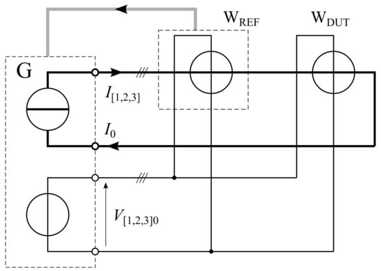
Figure 1.
Simplified schematic diagram of the phantom power test bed for calibration/verification of static electricity meters. See Section 3.2.2 for detailed description.
2.2. Meters under Test
We tested as WWDUT a series of static energy meters: (i) an high-end multi-function static three-phase meter representative of typical on-site meters at the point of common coupling, labeled DUT-1; (ii) five DIN-mounting meters—one three-phase meter (DUT-2) and four single-phase meters (DUT-3, …, DUT-6), representative of possible user-deployed meters inserted in production lines or at other appliances (office, workshop). Relevant specifications of the meters under test in this work are reported in Table 1.

Table 1.
Static energy meters under test. The EN class, and are defined following the standard EN 50470-1.
2.3. Standardised Sinusoidal and Distorted Waveforms
The sinusoidal and standardised distorted waveforms used to test the DUTs were implemented following the standardised tests (i) EN 50470 8.7.2 “Accuracy tests at reference conditions” and (ii) EN 50470 8.7.7.7 “Accuracy in presence of harmonics” in which the voltage waveform includes the 5th harmonic of amplitude equal to the 10% of the fundamental and the current waveforms include the 5th harmonic of amplitude equal to 40% of the fundamental. These tests served as a reference against tests performed with on-field recorded distorted waveforms, see Section 2.4.
2.4. On-Field Recorded Waveforms
2.4.1. Recording
The measurements performed in the field were made in September 2021, during the morning, at the point of common-coupling of a self-production photovoltaic (PV) generation/consumption facility belonging to a Italian small factory. The facility is connected to a substation of the Italian distribution network, and the energy meter accounts for both energy generation and absorption occurring in the factory, in turn depending on the self-consumption and light irradiation of the PV modules. A GESIS 2020 OM 330 energy meter is installed at the site, having a reference current , maximum current , belonging to the EN class B for active energy measurement. The meter is installed in semi-direct insertion, using TA transducers having a ratio and a IEC class 0.5 s. During the active hours of the factory/plant operation, voltage waveforms relative to the neutral conductor (, , ) and current waveforms (, , ) were sampled using a calibrated ZERA reference portable wattmeter model MT310. The specified instrument accuracy is of % in direct insertion and of % when employing amperometric clamps. The sampling instrument was inserted in 4 W mode, using amperometric clamps. The recording voltage and current ranges are and . It was used to record the harmonic content and the waveforms of the three voltage and current channels, plus other quantities of interest. Data storage format is xml, analyzed off-line.
2.4.2. Reproduction
To reconstruct the on-field recorded voltage and current waveforms, we used their harmonic content measured by the portable instrument MT310. The amplitude and phase of each of the 40 harmonic components of each channel were set on G by the software WinSAM™.
3. Results
The DUTs described in Section 2.2 were tested with the three types of waveforms: sinusoidal (Section 2.3), standardised distorted (Section 2.3) and on-field recorded (Section 2.4).
Following the standard EN 50470-1, the active energy relative error of the DUT is in a given condition is defined as
where EA,DUT is the active energy measurements of WDUT and EA,REF is the active energy measurements of the WREF.
The error e of the three-phase meters DUT-1 and DUT-2 was measured using the direct insertion scheme of Figure 1, with a 4 W connection. For the measurement of the error e of the single-phase meters DUT-3 to DUT-6, these were connected to the phase 2 of the test bed, following their specific connection schemes. In all cases one DUT at a time was connected to avoid unwanted loading of the instrumentation or other effects.
In all tests, the amplitude of voltage fundamental harmonic component, as reproduced in the laboratory, was set to , the standard reference voltage as defined in the EN 50470-1 (clause 4.1); in particular, the voltage waveforms recorded on the field were compatible with that amplitude. In fact, THDV for all the three phases is within the limit reported on the standard EN 50470-3 (Table 12). The amplitude of the fundamental harmonic of the current waveforms was proportionally reduced to comply with the specifications of WDUT (e.g., DUT-1 has a maximum current of ). For each voltage waveform, measurements were performed with different RMS currents in the range 0.25 A to 15 A; the individual current points have been chosen to be compatible with the specific DUT and include the reference currents Iref of Table 1.
For each measurement point, the readings of WREF were averaged for 20 under sinusoidal and standardised distorted conditions, and for 40 for the on-field recorded distorted waveforms to derive EA,DUT and EA,REF in each of the three conditions. Each measurement was repeated 6 times to be consistent with the on-field verification measurement protocol.
3.1. Tests with Standardised Waveforms
Sinusoidal and standardised distorted waveforms were reproduced in the test bed with the following characteristics: in both cases the RMS amlitude of the voltage waveform fundamental harmonic component was 230 V and the relative phase between voltage and current fundamentals was θ = 0∘.
3.2. Tests with On-Field Recorded Waveforms
3.2.1. Recorded Waveforms in the Field
Relevant parameters of the waveforms recorded on the field, and considered in this work, are reported in Table 2. Summarizing, RMS voltages (UL1, …, UL3) and RMS currents (IL1, …, IL3) on the three phases had values of the order of 230 and 10 respectively, as measured at the secondary TA current transducers. The voltage and current total harmonic distortion, THDV and THDI, were of the order of % and % respectively. The phase angle between voltage and current waveforms and the active (P), reactive (Q) and apparent (S) energy instead took different values for each phase. Phase angle is given with the voltage channel as reference. The influence of TA transducers (which are installed on the verification site) is not discussed in the present work.

Table 2.
On-field waveform relevant parameters. UL and IL are the RMS current and voltage values of the recorded waveforms; THD stands for total harmonic distortion; the symbol represents the phase angle between voltage and current recorded on each phase (a positive value represents I in advance of V, i.e., capacitive power factor); symbols P, Q, S indicate active, reactive and apparent power respectively.
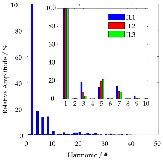
Examples of the current and voltage waveforms captured on the TA secondary winding at the verification site are shown in Figure 2. The plots show the waveforms in the time domain, and report strongly distorted current waveforms (solid lines) and clearly visible double zero-crossings. The corresponding voltage waveforms (dashed line) appear less distorted. Figure 3 shows the corresponding amplitude, of the 40 recorded harmonics of the current waveform on the phase 1, shown in Figure 2; the inset shows a detail of the first 10 harmonics, the most relevant, of all the three current waveforms (, , ) shown in Figure 2. For each phase, the amplitude of the harmonic components is normalized to the corresponding fundamental. Major harmonics have an odd index number, and the load was non-symmetric.
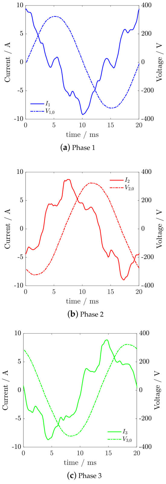
Figure 2.
Voltage and current waveforms on the three phases recorded at the facility. Data were stored in an MT310 verification instrument.
3.2.2. Measurements in the Laboratory
The relative phase between voltage and current waveforms were set according to the on-field measurements, resulting in a capacitive load-type for all the 3 phases. The energy measurement error e in sinusoidal and distorted conditions recorded on the field is reported in Figure 4 (DUT-1), Figure 5 (DUT-2) and Figure 6 (DUT-3, …, DUT-6). The horizontal dashed lines appearing in these figures represent the corresponding EN accuracy class for the considered DUTs. The vertical marker appearing in each figure represents the larger expanded uncertainty for that data set (coverage factor ) that has been estimated as follows. The type A uncertainty has been evaluated as the standard deviation of the mean of e readings. Type B contribution to the measurement uncertainty has been estimated on the basis of the uncertainty of the reference instrument WREF. This is within its class of % (50 ppm) when considering sinusoidal conditions and a power factor better than 0.5i or 0.8c; this has been verified by comparison with the Italian standard of power and energy. In this experiment, the power factor of the three-phase signal is about 0.23c, and that of the single-phase signal is about 0.4c. Anyway, despite the significant THDI (up to %), the THDV is limited (1.42% maximum), it is expected that less than 1% of the active power EA is provided by the harmonics. Taking these effects in consideration, we conservatively estimate the type B uncertainty of the measurements by applying a de-rating factor of 5 to the instrumental class of the WREF, with a rectangular distribution. This gives a type B contribution to the relative uncertainty of the active power measurement of % (300 ppm, ); this is comparable or smaller to the corresponding type A contribution estimated from the measurement error e readings. A proper expression of measurement uncertainty of a reference meter under low power factor and non-sinusoidal conditions is presently considered a research subject in itself [25,26].
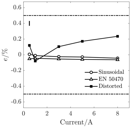
Figure 4.
Relative error, e, between WREF and WDUT for measurements performed with the DUT-1. Black markers represent the error on the measurement of reproduced distorted waveforms; white circles correspond to sinusoidal conditions and white triangles to the standardised distorted conditions. Horizontal dashed lines indicate the accuracy class according to EN 50470; the vertical marker represents the worst combined uncertainty which is %.
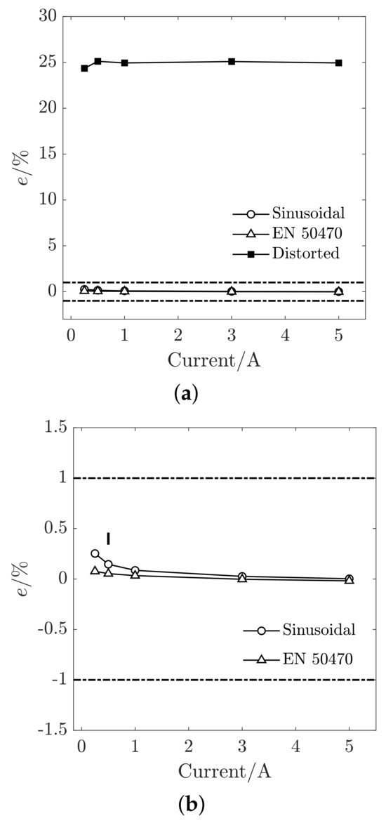
Figure 5.
Relative error, e, between WREF and WDUT for measurements performed with DUT-2. In (a) Black markers represent the error on the measurement of reproduced waveforms; white circles correspond to sinusoidal conditions and white triangles to the standardised distorted conditions. Horizontal dashed lines indicate the accuracy class according to EN 50470; in (b) the detail of e in sinusoidal and standardised distorted conditions. The vertical solid marker represents the worst combined uncertainty (%).
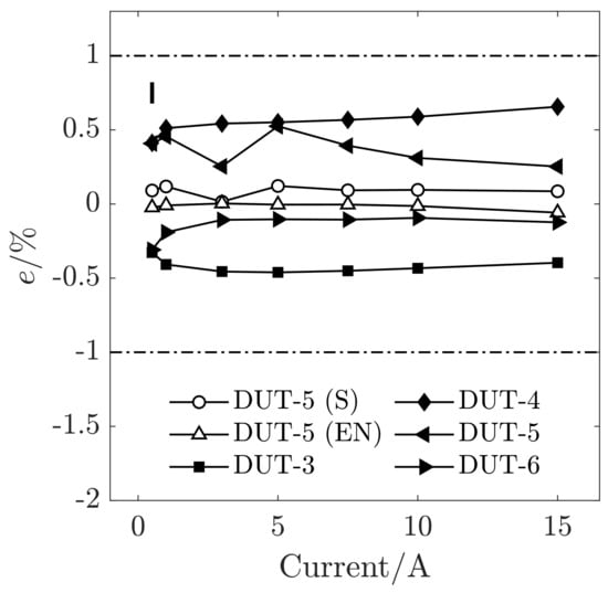
Figure 6.
Relative error, e, between WREF and WDUT for measurements performed with DUT-3 to DUT-6. Black markers represent the error on the measurement of reproduced distorted waveforms; white circles correspond to sinusoidal conditions and white triangles to the standardised distorted conditions, labeled as and (EN) respectively in the legend, here reported as a reference for DUT-5 only for sake of clarity. The horizontal dashed lines indicate the accuracy class of the DUTs according to EN 50470; the vertical marker represents the worst combined uncertainty among all the measurements, equal to %.
4. Discussion
Concerning DUT-1, Figure 4 shows that the error e of WDUT ranges between % and % in the sinusoidal regime, and between % and % in the standardised distorted regime, thus within the prescribed range of the standards EN 50470 and IEC 62053 for the class of DUT-1 (%). The error e corresponding to the reproduced distorted regime is larger: from % to %. Therefore, assuming the the power quality conditions as recorded in the field, although e of DUT-1 becomes larger in non-sinusoidal conditions, DUT-1 is still reasonably performing.
We now discuss the results obtained with the three-phase DIN-mounting meter labelled as DUT-2. Concerning DUT-2, Figure 5 shows that the error e of the WDUT spans between % and % for the sinusoidal conditions, and between % and % in standardised distorted conditions, thus falling abundantly within its accuracy class (%). Instead, the error e corresponding to the reproduced distorted conditions is much larger, taking values between % and %. Hence, DUT-2 is not performing well compared to WREF under the power quality conditions recorded on the field (The fact that the DUT-2 does not perform well under realistic distorted conditions can not be discussed in depth since it is a packaged commercial product. The different behaviour compared to DUT-1 might be related to the fact DUT-2 is a lower marked-price instrument, at difference with DUT-1 which is high-end product.). This result, should not be much surprising in non-sinusoidal conditions, since similar behaviours were observed recently in similar tests in distorted condition [27].
Finally we consider the results obtained with the single-phase DIN-mounting meters labelled as DUT-3, DUT-4, DUT-5 and DUT-6. Figure 6 groups the error e of DUT-3 to DUT-6. Overall, the active energy measurement error e spans between % and % for the sinusoidal conditions, falling even in this case within the range prescribed by the corresponding standards EN 50470 and IEC 62053 for the class of DUT-1 (%). For sake of clarity, in this plot we only reported the error in sinusoidal (S), and standardised distorted (EN) conditions for DUT-5, as representative; the corresponding errors for the other single-phase DUTs were comparable. The error e corresponding to the distorted conditions is larger, falls always within the accuracy class of these meters (%), spanning from % to %. In summary, under the power quality conditions recorded on the field, the measurement error e of DUT-3 to DUT-6 is comparable or larger to that observed in sinusoidal conditions, and the DUTs are reasonably performing when compared to WREF.
Note that the present standards [11,13] give no prescriptions regarding limits for the error e in a generic low power quality situation. Therefore, the results achieved under the reproduced distorted conditions cannot be formally compared with any of the defined forms of permissible error found in the present EN/IEC standards. Except for one energy meter (DUT-2) even highly distorted conditions are measured within the accuracy class (used as a reference) of the considered meters.
5. Conclusions
The measurement of energy under distorted conditions in distribution networks is a well-known issue. We developed a test bed in phantom power configuration for the reproduction, in laboratory conditions, of voltage and current waveforms, reconstructing them from the harmonic content of waveforms sampled on the field. The test bed was employed to perform verification tests on several three-phase and single-phase power meters, both in sinusoidal and distorted conditions. The outcome of the verification is strongly dependent on the meter model: some behave consistently with their accuracy class even under distorted power conditions, whereas others have errors up to % without warning to the user.
The approach implemented in the test bed is proposed as complementary to both the normative approach, where rigid waveform shapes with predefined harmonic content are prescribed, and the statistical approach proposed in scientific literature.
The results on DUT-2 reported in Figure 5 show that a meter model can be compliant to present standards, and indeed show a low error under either sinusoidal or standard distorted waveforms, and nevertheless have an unacceptable error under field conditions. This suggests that the tests described in the standards might not to be fully representative of the behaviour of an energy meter under real conditions.
The present paper focused on the behavior of commercial meter under realistic high harmonic content of the voltage and current waveforms, which of course does not exhaust the set of power quality parameters considered by the standards. The proposed approach can be extended to other events or conditions, e.g., DC content, transients or phase jumps, recorded in the field.
Author Contributions
Conceptualization, L.C., A.C., B.T., D.S. and F.G.; methodology, L.C., B.T., F.G., A.C., D.S. and M.C.; software, A.C., G.G., D.S. and B.T.; validation, B.T., D.S. and G.G.; investigation, A.C., G.G., D.S. and M.C.; resources, B.T., D.S, L.C. and F.G.; writing—original draft preparation, A.C.; writing—review and editing, A.C., L.C., B.T. and F.G.; visualization, A.C.; supervision, L.C. and A.C.; project administration, G.A.; funding acquisition, L.C. and F.G. All authors have read and agreed to the published version of the manuscript.
Funding
This work is supported by (i) the agreement “Collaboration for the development of validation methods for electrical energy meters under realistic conditions, towards market surveillance and consumer protection” between the Ministero dello Sviluppo Economico (MISE) and the Istituto Nazionale di Ricerca Metrologica (INRIM), (ii) the Italian Ministry of University and Research (MUR) in the framework of the continuing-nature project “NEXT-GENERATION METROLOGY”, under the allocation of the Ordinary Fund for research institutions (FOE) 2023 (Ministry Decree n. 789/2023).
Data Availability Statement
Research data supporting the reported results are available upon reasonable request to the corresponding author.
Conflicts of Interest
The authors declare no conflict of interest.
References
- Bollen, M.H.J. What is power quality? Electr. Power Syst. Res. 2003, 66, 5–14. [Google Scholar] [CrossRef]
- Lumbreras, D.; Gálvez, E.; Collado, A.; Zaragoza, J. Trends in Power Quality, Harmonic Mitigation and Standards for Light and Heavy Industries: A Review. Energies 2020, 13, 5792. [Google Scholar] [CrossRef]
- Salem, W.A.A.; Ibrahim, W.G.; Abdelsadek, A.M.; Nafeh, A.A. Grid connected photovoltaic system impression on power quality of low voltage distribution system. Cogent Eng. 2022, 9, 2044576. [Google Scholar] [CrossRef]
- Silva, J.I.; Sousa, V.; Sarmiento, P.; Gómez, J.R.; Viego, P.R.; Quispe, E.C. Effects of power electronics devices on the energy quality of an administrative building. Int. J. Power Electron. Drive Syst. 2019, 10, 1951. [Google Scholar] [CrossRef]
- Khalid, M.R.; Alam, M.S.; Sarwar, A.; Asghar, M.S.J. A Comprehensive review on electric vehicles charging infrastructures and their impacts on power-quality of the utility grid. eTransportation 2019, 1, 100006. [Google Scholar] [CrossRef]
- Cetina, Q.; Roscoe, R.A.J.; Wright, P.S. Challenges for smart electricity meters due to dynamic power quality conditions of the grid: A review. In Proceedings of the 2017 IEEE International Workshop on Applied Measurements for Power Systems (AMPS), Liverpool, UK, 20–22 September 2017; pp. 1–6. [Google Scholar] [CrossRef]
- Ten Have, B.; Hartman, T.; Moonen, N.; Leferink, F. Misreadings of static energy meters due to conducted EMI caused by fast changing current. In Proceedings of the 2019 Joint International Symposium on Electromagnetic Compatibility, Sapporo and Asia-Pacific International Symposium on Electromagnetic Compatibility (EMC Sapporo/APEMC), Sapporo, Japan, 3–7 June 2019; pp. 445–448. [Google Scholar] [CrossRef]
- Ten Have, B.; Hartman, T.; Moonen, N.; Keyer, C.; Leferink, F. Faulty readings of static energy meters caused by conducted electromagnetic interference from a water pump. Renew. Energy Power Qual. J. 2019, 17, 15–19. [Google Scholar] [CrossRef]
- 2014/32/EU; Directive 2014/32/EU of the European Parliament and of the Council of 26 February 2014 on the Harmonization of the Laws of the Member States Relating to the Making Available on the Market of Measuring Instruments. European Parliament and the Council of the European Union: Brussels, Belgium, 2014.
- EN 50470-1:2006+A1:2018; Electricity Metering Equipment (A.C.)—Part 1: General Requirements, Tests and Test Conditions—Metering Equipment (Class Indexes A, B and C). CENELEC: Brussels, Belgium, 2018.
- EN 50470-3:2022-06; Electricity Metering Equipment (A.C.)—Part 3: Particular Requirements—Static Meters for Active Energy (Class Indexes A, B and C). CENELEC: Brussels, Belgium, 2022.
- EN 62052-11:2021-04; Electricity Metering Equipment—General Requirements, Tests and Test Conditions—Part 11: Metering Equipment. IEC: Geneve, Switzerland, 2021.
- EN 62053-21:2021-04; Electricity Metering Equipment—Particular Requirements—Part 21: Static Meters for AC Active Energy (Classes 0, 5, 1 and 2). IEC: Geneve, Switzerland, 2022.
- CEI 13-71; Sistemi di Misura dell’Energia Elettrica (c.a.)—Guida Alla Composizione, Installazione e Verifica. CEI: Milano, Italy, 2022.
- Quijano Cetina, R.; Seferi, Y.; Blair, S.M.; Wright, P.S. Energy metering integrated circuit behavior beyond standards requirements. Energies 2021, 14, 390. [Google Scholar] [CrossRef]
- Bartolomei, L.; Cavaliere, D.; Mingotti, A.; Peretto, L.; Tinarelli, R. Testing of Electrical Energy Meters Subject to Realistic Distorted Voltages and Currents. Energies 2020, 13, 2023. [Google Scholar] [CrossRef]
- Olencki, A.; Mróz, P. Testing Of Energy Meters Under Three-Phase Determined And Random Nonsinusoidal Conditions. Metrol. Meas. Syst. 2014, 21, 217–232. [Google Scholar] [CrossRef]
- Ferrero, A.; Muscas, C. On the selection of the “best” test waveform for calibrating electrical instruments under nonsinusoidal conditions. IEEE Trans. Instrum. Meas. 2000, 49, 382–387. [Google Scholar] [CrossRef]
- Ferrero, A.; Faifer, M.; Salicone, S. On Testing the Electronic Revenue Energy Meters. IEEE Trans. Instrum. Meas. 2009, 58, 3042–3049. [Google Scholar] [CrossRef]
- Gallo, D.; Landi, C.; Pasquino, N.; Polese, N. A New Methodological Approach to Quality Assurance of Energy Meters Under Nonsinusoidal Conditions. IEEE Trans. Instrum. Meas. 2007, 56, 1694–1702. [Google Scholar] [CrossRef]
- Durante, L.; Ghosh, P.K. Active power measurement in nonsinusoidal environments. IEEE Trans. Power Syst. 2000, 15, 1142–1147. [Google Scholar] [CrossRef]
- van den Brom, H.E.; van Leeuwen, R.; Marais, Z.; ten Have, B.; Hartman, T.; Azpúrua, M.A.; Pous, M.; Kok, G.J.; van Veghel, M.G.; Kolevatov, I.; et al. EMC testing of electricity meters using real-world and artificial current waveforms. IEEE Trans. Electromagn. Compat. 2021, 63, 1865–1874. [Google Scholar] [CrossRef]
- Callegaro, L.; Aprile, G.; Cultrera, A.; Galliana, F.; Germito, G.; Serazio, D.; Trinchera, B. A calibration-verification testbed for electrical energy meters under low power quality conditions. Meas. Sens. 2021, 18, 100188. [Google Scholar] [CrossRef]
- Cultrera, A.; Germito, G.; Serazio, D.; Galliana, F.; Trinchera, B.; Aprile, G.; Chirulli, M.; Callegaro, L. Laboratory reproduction of on-field low power quality conditions for the calibration/verification of electrical energy meters. In Proceedings of the 25th IMEKO TC-4 International Symposium on Measurement of Electrical Quantities, Brescia, Italy, 12–14 September 2022; pp. 29–32. [Google Scholar]
- Djokić, B.; Parks, H. Calibration of Electrical Instruments Under Nonsinusoidal Conditions at NRC Canada. IEEE Trans. Instrum. Meas. 2021, 70, 1–6. [Google Scholar] [CrossRef]
- Yang, S.; Yan, A.Y.K.; Ng, C.M.N. High accuracy and traceable power quality instrument calibration using high-speed digitizing technique. In Proceedings of the Conference on Precision Electromagnetic Measurements (CPEM), Ottawa, ON, Canada, 10–15 July 2016; pp. 1–2. [Google Scholar] [CrossRef]
- Macedo, J.R.; Xavier, G.L.; Gondin, I.N.; Oliveira, L.T.; de Oliveira, R.F. An update on the performance of active energy meters under non-sinusoidal conditions. Electr. Eng. 2020, 102, 1785–1794. [Google Scholar] [CrossRef]
Disclaimer/Publisher’s Note: The statements, opinions and data contained in all publications are solely those of the individual author(s) and contributor(s) and not of MDPI and/or the editor(s). MDPI and/or the editor(s) disclaim responsibility for any injury to people or property resulting from any ideas, methods, instructions or products referred to in the content. |
© 2024 by the authors. Licensee MDPI, Basel, Switzerland. This article is an open access article distributed under the terms and conditions of the Creative Commons Attribution (CC BY) license (https://creativecommons.org/licenses/by/4.0/).
