Article

Numerical Analysis of Three Vertical Axis Turbine Designs for Improved Water Energy Efficiency

1
Department of Civil Engineering, Izmir Institute of Technology, Izmir 35430, Turkey
2
Department of Civil and Environmental Engineering, Norwegian University of Science and Technology, 7491 Trondheim, Norway
3
Department of Civil Engineering, Izmir University of Economics, Izmir 35330, Turkey
*
Author to whom correspondence should be addressed.
Energies 2024, 17(6), 1398; https://doi.org/10.3390/en17061398
Submission received: 19 January 2024 / Revised: 26 February 2024 / Accepted: 12 March 2024 / Published: 14 March 2024

Abstract

:
A hydrokinetic turbine with a vertical axis is specifically designed to harvest the kinetic energy from moving water. In this study, three vertical axis water turbines, namely Gorlov, Darrieus, and Savonius turbines, were compared for their efficiency via numerical modeling for steady-state conditions via the ANSYS 2022 R2 Fluent model. The Semi-Implicit Method for Pressure-Linked Equations (SIMPLE) was implemented with an SST k-ω turbulence model. The dynamic mesh technique, which allows modeling according to changes in angular velocity at each time step, was used to simulate flow around the turbines for six different velocities (from 0.5 to 3 m/s). The efficiency of the turbines was compared and the results were analyzed. The pressure, velocity, and turbulence kinetic energy distributions around the rotor were measured at different rotational angles and results indicated a wider operating range for the Darrieus and Gorlov turbines compared to the Savonius turbine. The highest power coefficient of 0.293 was achieved in the model featuring a Darrieus turbine, corresponding to a TSR value of 1.34, compared to 0.208 for the Gorlov and 0.257 for the Savonius turbine, at TSR values of 1.3 and 1.06, respectively. Numerical modeling results pointed to a significantly higher self-starting capacity for the Savonius turbine compared to the others.

1. Introduction

Providing adequate energy is crucial for economic expansion and raising the living standards globally. Electrical energy is a fundamental component in the digitalized and industrialized society and is essential for the great majority of daily activities. Electricity is generated by power plants using various sources of power. These fundamental energy sources can be classified as renewable sources, including wind, solar radiation, and water, and non-renewable sources, including but not limited to coal, natural gas, and oil. Renewable energy refers to the utilization of resources that can be naturally replenished over a human timeline. This category incorporates sources such as solar radiation, wind, flowing river water, ocean waves, and geothermal heat [1].
By the end of 2019, installed renewable energy capacity accounted for 27.3% of worldwide electricity generation, with hydropower being the main contributor (58.46%) to the renewable global total [2]. Hydraulic power, or hydroelectric energy, is a sustainable energy source that generates electricity by modifying the natural course of a river or another water body through a dam or redirection structure. According to power capacity, hydroelectric power plants can be categorized as large, medium, small, mini, micro, and pico [3]. Large-scale hydroelectric power plants produce a great deal of power but, unfortunately, have environmental drawbacks, requiring the construction of a dam and a reservoir. Dams may restrict the movement of fish and other marine creatures. A reservoir and a dam can alter the climate, as well as the flow characteristics, temperature, marine life diversity, chemistry, and silt load quantities. These environmental influences have the potential to alter the river’s upstream and downstream ecology and these changes can affect the deltas that form when rivers flow into the ocean. In addition, reservoirs can engulf enormous areas, agricultural lands, and habitats and sometimes cause forced migration. Depending on the temperature and location, they may also hold a significant quantity of greenhouse gases [4].
For rural electrification projects, small-scale hydropower is a highly cost-effective and ecologically beneficial technology. A conventional micro hydropower plant, however, must divert water from the river and transport it to the turbines, while maintaining the same elevation or head. In contrast to diesel-powered generators (DGs), traditional micro hydropower has significantly higher initial capital expenditures but far lower operating costs [5]. The drawback of normal small-scale hydropower, however, is that it is typically derived from run-of-river plants with a limited water storage capacity [6,7].
Hydrokinetic energy holds the promise of making a substantial contribution to renewable and clean energy generation, particularly in areas with abundant water resources. It represents an innovative approach to hydropower energy generation, producing electricity by harnessing the kinetic energy of moving water rather than relying on the gravitational potential energy of descending water. This sets it apart from traditional hydropower generation methods. The system exhibits similarities to wind turbine systems in terms of electrical components, operational principles, and its ability to operate at variable velocities to maximize energy harvesting. Water is more than 800 times denser than air and, therefore, hydrokinetic turbines have the potential to harvest significant energy, even at low speeds [8,9,10]. This approach enables electricity production without the need for dams or other expensive infrastructure [11,12]. Moreover, compared to other renewable energy sources, this technology is becoming more appealing due to its high-density energy production, reliable predictability, and low impact on the environment [13,14]. This approach is also feasible for isolated settlements and farms near rivers at low or no elevations where conventional micro-hydroelectric generation is impossible [15]. This clearly demonstrates that far more potential sites exist for hydrokinetic technology compared to classic hydropower production [16]. However, this technology is currently at an early stage of development and even in rural areas with sufficient water resources, there is a lack of applications [7].
Many review articles have appeared on hydrokinetic energy conversion mechanisms. Khan et al. [8] defined the conversion of river current power systems and offered an outline of the related technological achievements. Lago et al. [17] studied the comparisons and categorizations of energy transformation systems. Güney and Kaygusuz [18] classified hydrokinetic turbines and identified types suitable for river and tidal currents. Vermaak et al. [7] investigated hydrokinetic technology applications for remote and rural areas. Kumar and Nikhade [19] described a range of hybrid kinetic turbine rotor approaches with applications and provided a comparison of types. Kumar and Sarkar [20] focused on turbine performance and environmental impacts and Niebuhr et al. [21] focused on turbine design and modeling. Improving the performance and optimizing the design of crossflow hydrokinetic turbines were explored by Saini and Saini [22]. The energy cost and challenge of hydrokinetic technology were explored by Sood and Singal [23]. Ibrahim et al. [24] traced the historical development of marine and river applications for different turbine types and compared current commercial technologies in terms of working principles. Kamal and Saini [25] reviewed various researchers’ adjustments to enhance the performance properties of single and hybrid hydrokinetic turbines and described some numerical and experimental methods for evaluating the performance of the crossflow hydrokinetic system. Li et al. [26] and Li et al. [27] presented fluid–structure coupling modeling and real-time sensing methods for both MFSV (multiphase free sink vortex)-induced and GCVF (gas–liquid coupled vortex flow)-induced vibrations for hydroelectric energy conversion.
Various experimental and numerical investigations available in the literature are listed in Table 1. Here, D (mm) is the turbine diameter, H (mm) is the turbine height, c (mm) is the chord length of the blade, W (m) is the width of the channel, Hw (m) is the water height in the channel, L (m) is the length of the water in the channel, and d (mm) is the diameter of the shaft. The table shows the details of the turbine types and properties cited in the available studies and the maximum power efficiency (CP) achieved during experimental/numerical analyses. According to the table, the Darrieus type turbine reached higher power efficiencies in higher flow conditions. The power coefficient of the Gorlov turbine reached a maximum of 0.416 and the Savonius reached a maximum of 0.39. These studies correspond to a minimum flow velocity of 0.5 m/s and a maximum value of 2.8 m/s. The diameter of these turbines varied between 160 and 2000 mm and the height varied between 160 mm and 1320 mm. In numerical studies, the SST k-ω turbulence model is commonly utilized.
There are primarily two classifications for hydrokinetic turbines, axial flow turbines and crossflow turbines, as shown in Figure 1 [43]. Axial flow turbines, which have a horizontal axis of rotation parallel to the water’s flow direction, achieve optimal power conversion efficiency when their rotor plane is perpendicular to the flow. These turbines are typically favored in marine and aquatic environments [23]. Conversely, crossflow turbines have a rotational axis that is oriented orthogonally to the flow direction. Their cylindrical design allows for efficient use of channel depth and they can harness energy from flow in various directions. Depending on the specific torque and flow conditions required, crossflow hydrokinetic turbines may be equipped with two, three, or more blades [22].
Table 2 compares various aspects of axial and crossflow turbines based on the findings of selected studies [8,15,21,22,43,44,45].
Although axial flow turbines have numerous benefits over crossflow turbines, in this study, vertical crossflow turbines were selected due to their higher efficiency in shallow waters, their simpler design, and lower cost. These turbines can perform efficiently in waters too shallow for axial flow turbines. They can also be installed in a broad spectrum of depths making them suitable for varying conditions. Also, they are less sensitive to changes in flow direction compared to axial flow turbines and they are able to harness energy from currents from different directions, making them well suited for locations with changing or unpredictable flow patterns. They have fewer moving parts and this greater simplicity can lead to reduced maintenance requirements and impact on aquatic life. Many researchers have suggested that crossflow turbines are appropriate for rivers and artificial canals [18,33,43,44].
In this study, three types of commonly studied vertical axis water turbines were numerically compared for their power efficiencies. We investigated the best turbine type under the same configurations, considering that the Darrieus and Gorlov rely on the lift force principle and the Savonius relies on the drag force principle. While making the analyses, the turbine rotation area was modeled with a dynamic mesh, rather than the sliding mesh technique used in many previous studies [38,46,47,48]. In this method, rather than assigning a specific rotation angle to the turbine, the model is run according to the angular velocity of the turbine, which changes depending on the water flow velocity.

2. Design of the Turbines

The four design parameters for vertical axis hydrokinetic turbines are the number and profile of blades, solidity, aspect ratio, and overlap ratio. The geometric parameters of the turbines utilized in this study are provided in Table 3. The turbine size was selected according to its suitability for the channel in the laboratory to be used in future experimental studies. Due to the accessibility of lift and drag data across a broad spectrum of Reynolds numbers, the design of vertical axis turbine blades has traditionally been designed using the symmetrical geometries from the well-established NACA 4-digit series [29]. Among the standard symmetric NACA airfoil profiles, the S-1046 symmetrical profile achieved the highest power coefficient [49,50]. Consequently, this configuration was also selected for the Gorlov and Darrieus turbine blade profiles for this study. A 43.7 degree inclination was identified as the most suitable angle chosen for the Gorlov turbine, due to its relatively higher torque values [28]. The chosen blade number (N) can affect the turbine’s capacity to self-start, as follows: three-blade rotors have demonstrated a better self-starting capability than the standard two- or one-blade Gorlov and Darrieus turbines [51,52,53]. Also, the two-bladed Savonius rotor has superior performance regarding the acquired torque and power coefficients [54,55]. Therefore, three blades were selected for Gorlov and Darrieus, and two for Savonius. The highest efficiencies are created with an overlap ratio (this is only relevant to the Savonius rotor) value ranging from 20% to 30% [55,56]. The Savonius turbine has a 0.256 overlap ratio. The Autodesk Inventor Professional 2021 program was used to create three-dimensional drawings of Gorlov, Darrieus, and Savonius turbine designs, as shown in Figure 2.

3. Performance Parameters

Several performance parameters were examined to quantify the efficiency characteristics. To assess the results, the turbine performance parameters were formulated as follows [7,18,57].
The turbine power output was expressed as the non-dimensional power coefficient. CP is the ratio of the real electric power generated by a turbine to the total water power flowing through the blades at a given water velocity.
C P = P T P A
where PT is the mechanical power developed by the rotation of the turbine and PA is the maximum available power that can be produced from the channel model.
P T = T × ω
where T is the torque of the turbine and ω is the angular velocity of the turbine.
P A = 1 2 × A × ρ × v 3
where A is the swept area of the rotor blades, ρ is the density of water, and v is the velocity of the flowing water.
The coefficient of torque, CT, represents the ratio between the area projected by the turbine at flow velocity and the torque generated by the turbine.
C T = T 0.5 ρ A v 2 R
where T is the turbine torque, ρ is the density of water, A is the swept area of the rotor blades, v is the velocity of the flowing water, and R is the radius of the turbine.
Tip speed ratio, λ , represents the ratio between the tangential speed of the blade tips and the actual velocity of water for turbines.
λ = R ω v
where R is the radius of the turbine, ω is the angular velocity of the turbine, and v is the velocity of the flowing water.

4. Modeling and Numerical Analysis

Three-dimensional CFD delivers the most accurate simulation of all CFD models, but also requires the highest level of computational resources. Jin et al. [58] compared computational outcomes derived from 2D CFD and 3D CFD simulation. The authors found that the experimental results were more approximative when utilizing 3D simulation for Darrieus turbine analysis. In this study, 3D simulation was, therefore, chosen as the most reliable for simulating the flow surrounding the turbines.

4.1. Turbulence Model and Governing Equations

To compute the various forces exerted on the blades, it is necessary to solve the continuity and momentum equations and then compute the momentary forces exerted on the blades to ascertain the net torque and net power produced within the specific water flow conditions in the channel [48]. The selection of the SST (Shear Stress Transport) k-ω turbulence model was based on its prior successful applications in simulating turbine performance. This model is favored for its capability to effectively simulate the free stream regions and the boundary layer. The model incorporates two equations that blend elements from both the k-ω and k-ε models. The SST k-ω model allows the accurate presentation of the flow characteristics near the walls, as well as in the far-wall regions [42,44,59,60,61]. The mass and momentum conservation equations are the fundamental conservation equations that govern the flow within the domain of vertical axis hydrokinetic turbines. The governing equations for incompressible, unsteady, and viscous flow, expressed in indicial (i, j, k) form, are as follows:
ρ t + ( ρ u i ) x i = 0
ρ D u i D t = ρ u i t + u j u i x j = ρ f i P x i + µ 2 u i x j x i

4.2. Model Domain and Boundary Conditions

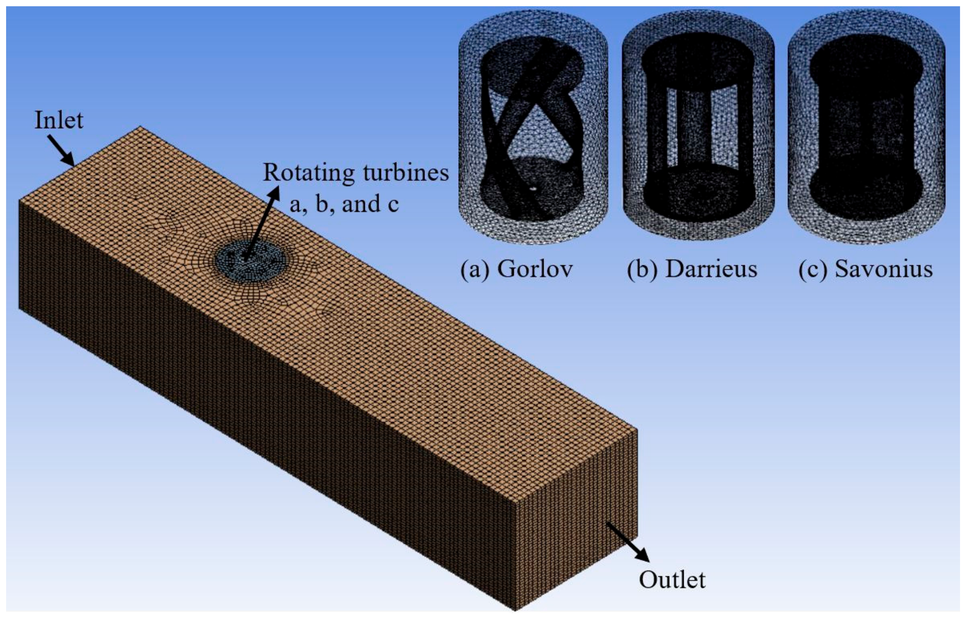
To determine the performance characteristics of hydrokinetic turbines, a 3D domain was created and split into two sections, one stationary and one rotating. The stationary part of the channel consists of the inlet, outlet, sidewalls, and top and bottom surface to represent the availability of water within the channel. The rotating part consists of a turbine operating at the same angular velocity (RPM) as hydrokinetic turbines. The turbine is positioned a third of the distance between the inlet domain and the channel. The open rectangular channel, which accommodated the turbine, had the following dimensions: 225 cm in length, 55 cm in width, and 40 cm in depth. In addition, the literature indicates that the domain of cylindrical rotating should be positioned at a distance of 10R (R is the radius of the turbine) from the inlet of the stationary channel domain, with its dimensions ranging from 2.5R to 6R [59,62,63]. A rotating domain significantly increases the computational capacity. Due to this, the rotating area was assumed to be 10R from the inlet, 20R from the outlet, and 3R in diameter. The model domain area and boundary conditions are shown in Figure 3.
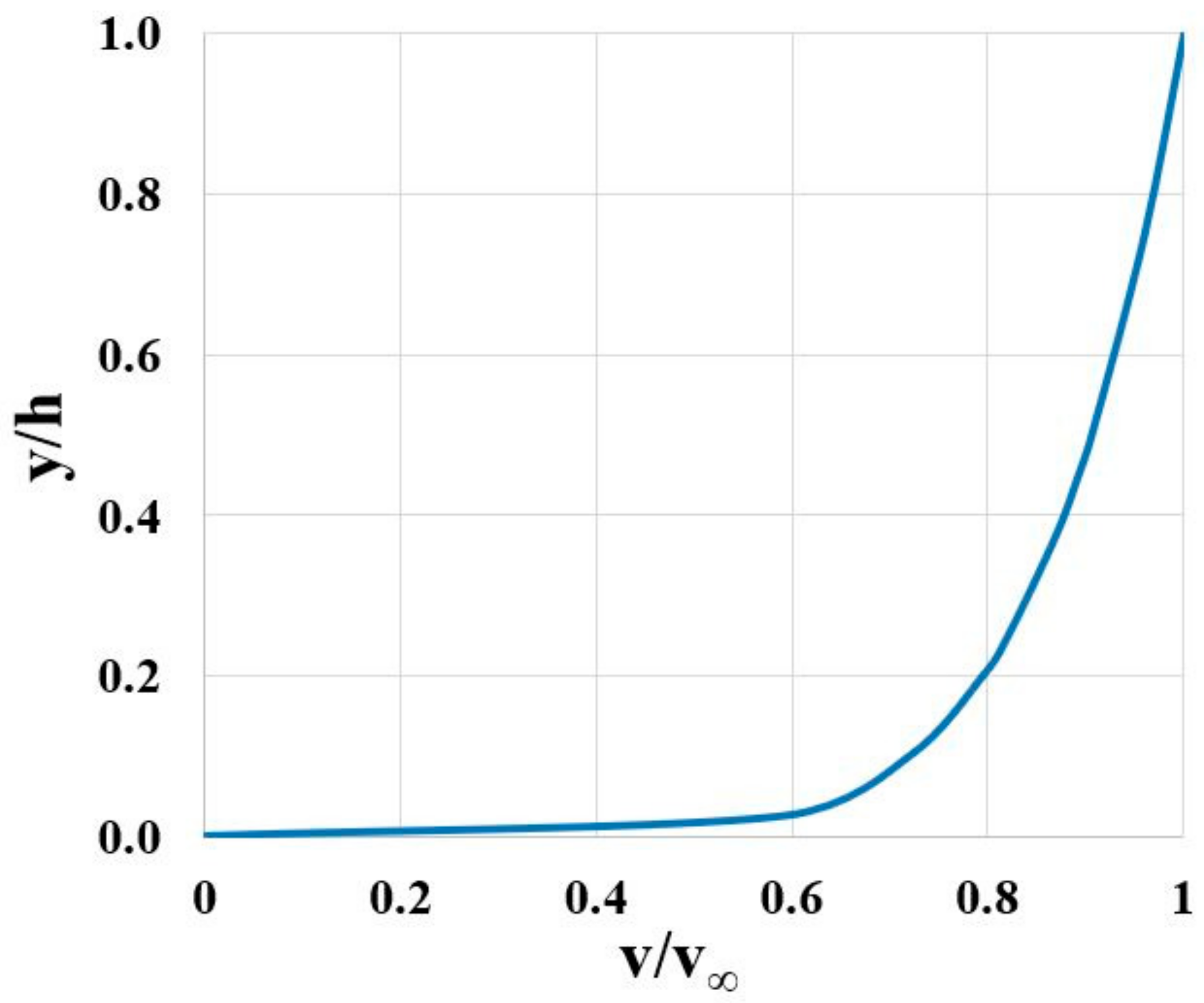
The cylindrical domain was subtracted from the vertical axis hydrokinetic turbine model to generate a rotating zone. The boundary conditions are initially specified within the mesh generator and subsequently applied in ANSYS 2022 R2 Fluent. A collection of restriction values provided at the outer limits of the computational domain are referred to as boundary conditions [64]. In this study, a velocity profile of water at the inlet of a channel was specified in order to simulate the flow condition in open channels. The velocity profile was defined using the formula in Equation (8) and the “USER_DEFINE_PROFILE” method was used to characterize a boundary profile that varies as a function of spatial coordinates or time [65]. A graph of the velocity profile at the inlet is shown in Figure 4. Atmospheric pressure is presumed to exist at the outlet of the channel. At the bottom surface and side walls of a stationary computational sub-domain, the relative velocity of the fluid is considered to be zero and these surfaces are considered solid boundaries. The fluid velocity is completely nullified in the no-slip condition, where the cohesive force between fluid particles is negligible compared to the adhesive force between fluid and solid particles. Consequently, the side walls and bottom surface of the channel were subject to a “no-slip” boundary condition [64]. It was assumed that turbines function at depths sufficiently deep to neglect free surface effects and this allowed for the application of symmetry, reducing the domain size, as noted in a previous study [66]. Table 4 details the location and values of boundary conditions at the channel. Moreover, turbulence intensity and turbulent viscosity ratio remained constant throughout the simulation setup. The turbulence intensity was 5%, while the turbulence viscosity ratio was 10 in the inlet.
v v = y h 1 7
where v is flow velocity at ‘y’ depth, v is free stream water velocity, y represents the depth at which velocity is computed, and h is the total channel depth.

4.3. Mesh Generation and Mesh Independency Testing

The mesh generation procedure, also known as grid generation, is a crucial component of CFD simulation. The outcomes of the solution are dependent on the quality of the mesh, specifically its size. In the process of mesh generation using ANSYS 2022 R2 Workbench, CFD was selected as the physics preference and Fluent as the solver preference. The face and body cells in the rotating area are defined as the turbine and rotating part, respectively. The stationary area was also used in the Hexa/prism mesh type with the pave mesh method. The mesh size was set to “fine” and smoothing was set to “medium”. Proximity and curvature were considered in order to calculate mesh size surrounding curved surfaces. The mesh of the turbines and computational domain is given in Figure 5.
In order to determine the type of mesh appropriate for the computations, a mesh-independency test was performed. The mesh independence limit (MIL) was reached when the refined mesh was optimized. To identify the limit of mesh independence, the power coefficient was monitored during the refinement process, following previous studies [37,41,42,48]. In this study, ten different levels of refinement were examined for each turbine. Table 5 lists a summary of the different levels of mesh refinement, including the number of elements, quality aspects, and mesh size. Skewness and orthogonal quality were determined to have a major effect on the power coefficient using regression analysis. The number of elements affects the accuracy of computational results. In addition, the same rotating and stationary mesh size values were chosen for all three turbines. Greater refinement levels increase the computational cost and the required time; consequently, in this study, the boldface denotes levels 5 for Gorlov, 6 for Darrieus, and 3 for Savonius to be suitable for future simulations (Table 5). The selected level 5 has 880,997 elements, featuring an aspect ratio of 1.87, an average skewness of 0.20, and an orthogonal quality of 0.80. The selected level 6 has 888,048 elements, featuring an aspect ratio of 1.85, an average skewness of 0.21, and an orthogonal quality of 0.80. The selected level 3 has 717,770 elements, featuring an aspect ratio of 1.85, an average skewness of 0.20, and an orthogonal quality of 0.80. After completion of appropriate mesh generation, the computational domain was transferred to the Fluent module for further analysis.
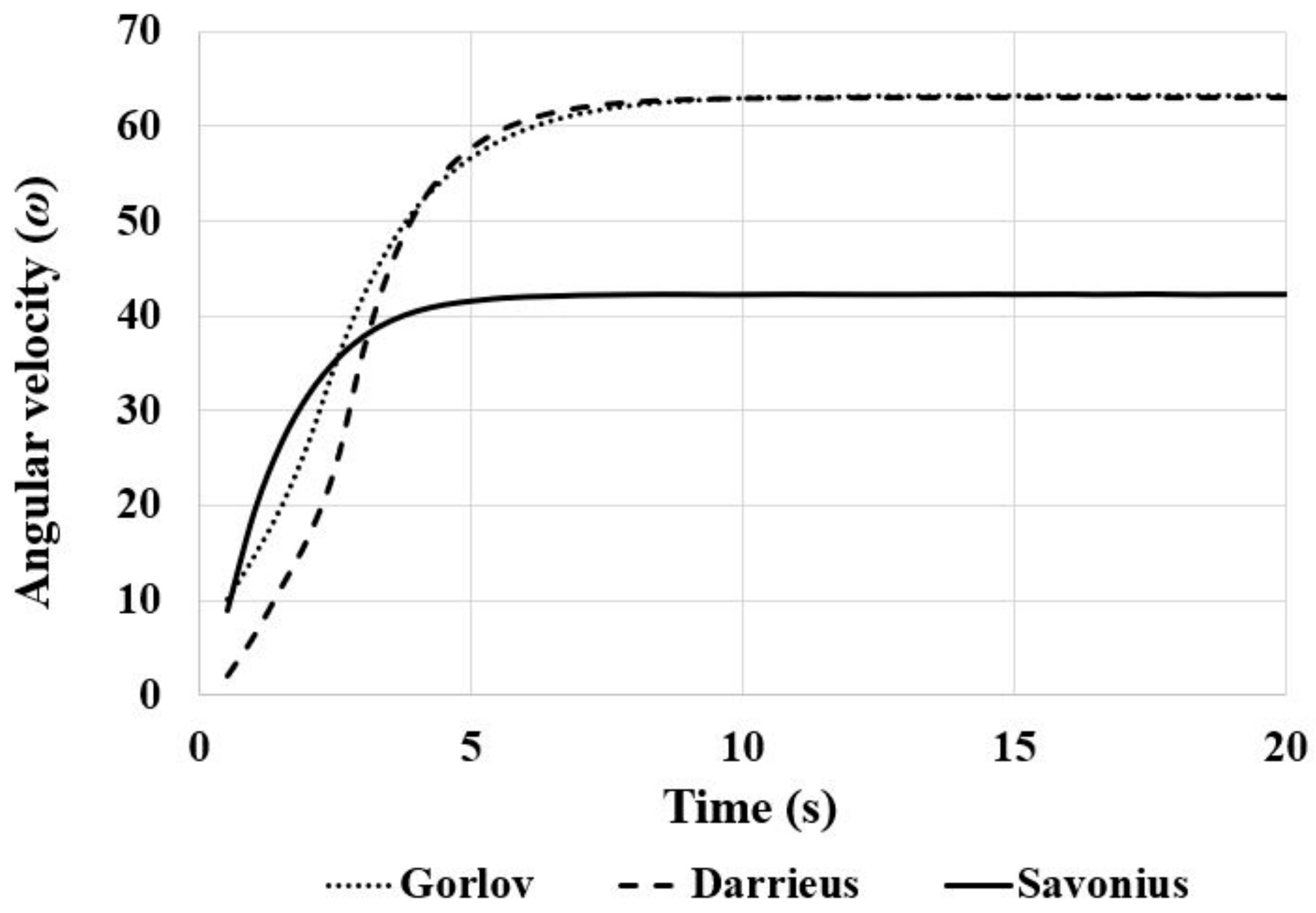
As a consequence of boundary motion, the dynamic mesh model in Fluent can be used to model flows in which the geometry of the domain changes over time [67]. In these simulations, it is presumed that the vertical axis water turbine is rotating within the water flow and this rotational motion affects the surrounding meshing. Hence, the dynamic mesh model defines the change in meshing surrounding a rotational turbine. To enhance the definition of the dynamic mesh, a cylindrical region (the rotating part) was isolated from the entire computational domain specifically to encompass the turbine. In this simulation, the rotation is modeled using the Dynamic Mesh 6DOF (Six Degrees of Freedom) method, which simulates turbine rotation based on its moment force. To identify the regions subject to the dynamic mesh, the turbine body’s walls and the distinct area surrounding the turbine are designated as rigid bodies. At the same time, the remaining domain parts are considered stationary. Designating a rotational motion with 1-DOF is necessary to characterize the rigid body motion. Hence, it is assumed that the moment of inertia is 0.1 kg.m2 and the turbine mass is 0.5 kg. The sliding mesh motion technique has a constant rotating velocity; in contrast, a new angular velocity is calculated during each time step of the dynamic mesh. The graph in Figure 6 shows the change in angular velocity value over time when the flow velocity is 2 m/s. In the simulations of this study, all analyses were modeled for 20 s with a time step of 0.01.
The dimensionless distance of the first layer from the wall y+ determines the mesh quality. The boundary layer that flows over the turbine blades describes the flow surrounding the turbine. The first prism layer above the blade surfaces of the turbine wall was considered according to a y+ value of <1. The mass and momentum conservation equations are the fundamental conservation equations that govern the flow within the domain of vertical axis hydrokinetic turbines.
To couple the velocity and pressure equations and enhance precision, it was decided to use the Semi-Implicit Method for Pressure-Linked Equations (SIMPLE) method [48,49,68,69]. All simulations used the SIMPLE pressure–velocity coupling method. For the equations representing momentum, turbulent kinetic energy, and specific dissipation rate, second-order upwind schemes were applied and, similarly, second-order discretization was utilized for the equations representing pressure. The software solves the flow-governing equations using the least squares cell-based gradient technique for spatial discretization. In each time step, convergence criteria were established with a threshold of 10−5 for the residuals of all momentum, continuity, and turbulence equations. Details of the numerical modeling parameters are given in Table 6.

5. Results and Discussion

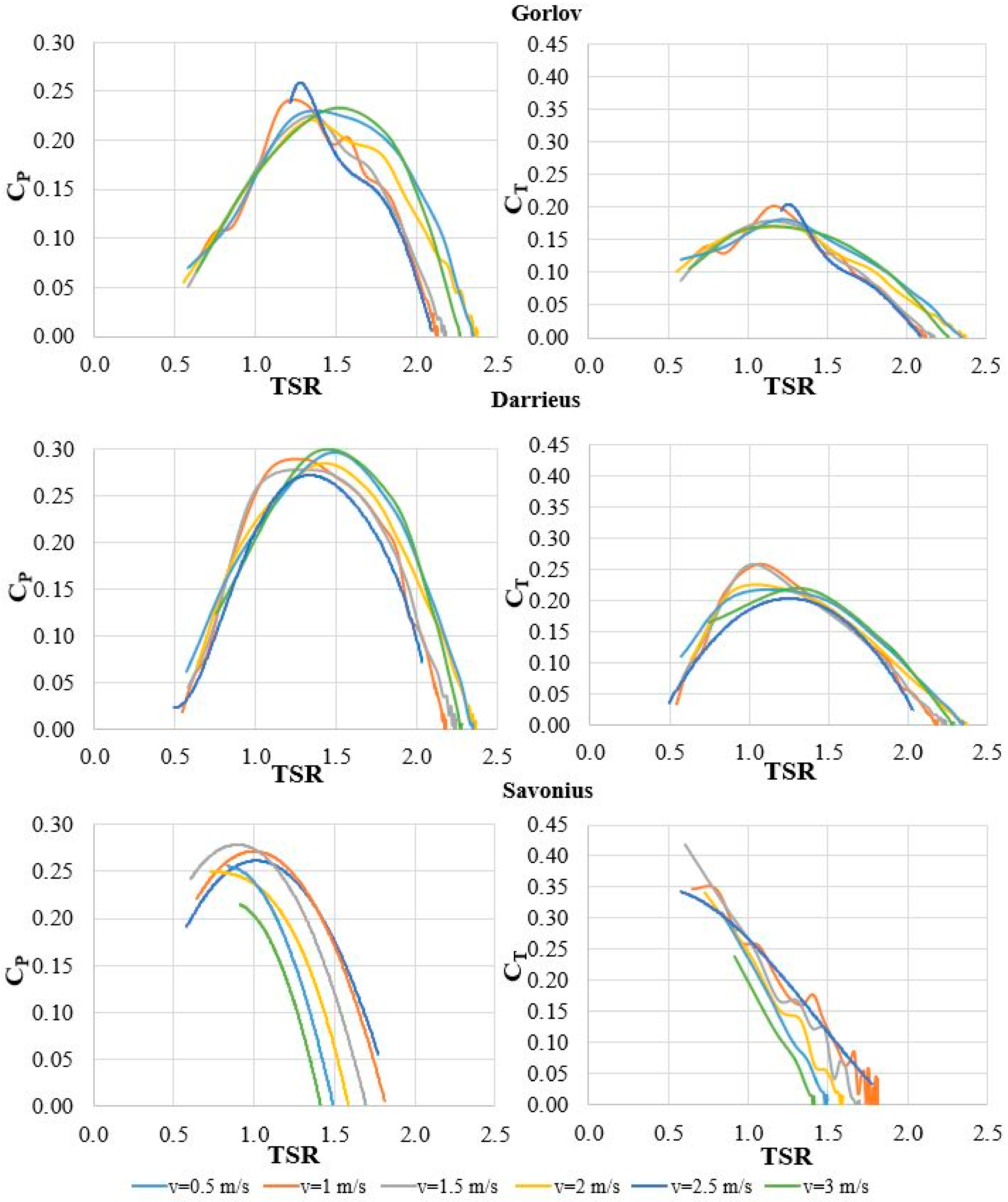
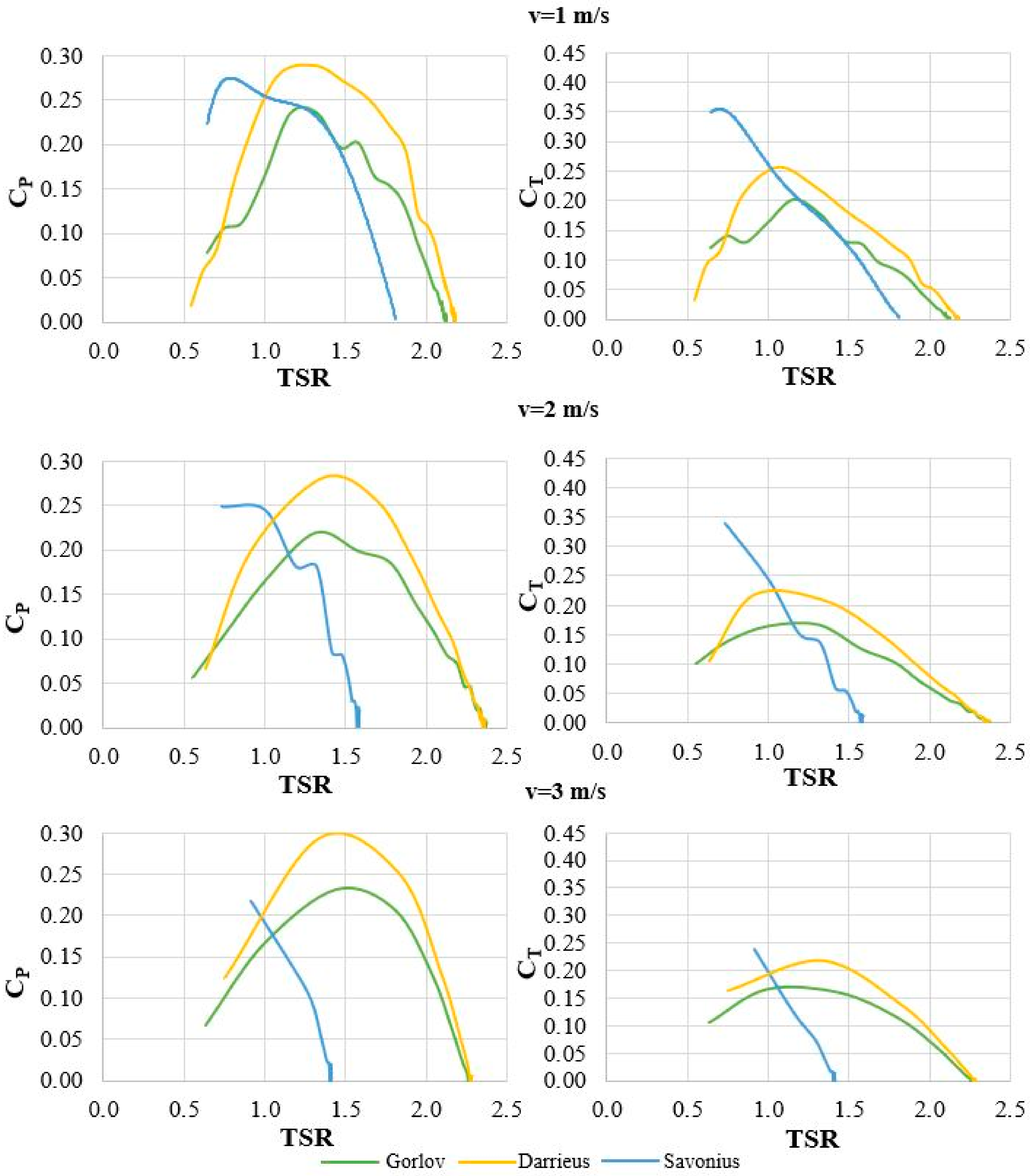
In this study, eighteen simulations were performed for various velocity values ranging from 0.5 to 3 m/s and TSR values ranging from 0.05 to 2.4 for the three different turbine types. The distribution of flow around the turbine is characterized according to the maximum CP and CT values. The flow conditions of water are expressed by pressure, velocity, and turbulence kinetic energy contours around the turbine rotor under different conditions. The turbine’s coefficient of power (CP) and coefficient of torque (CT) were computed by applying Equations (1) and (4), while considering various Tip Speed Ratio (TSR) values. Figure 7 shows the variations of CP and CT produced by the turbines, according to six different velocity values for different TSRs. In Figure 7, it is worth noting that the CP exhibits a gradual increase as the TSR rises, but then gradually decreases as the TSR continues to increase, denoting the TSR range within which the turbine operates most effectively.
The maximum power coefficient among all analyses was achieved by the Darrieus turbine, with a power coefficient of 0.293. This value was reached when the tip speed ratio was 1.34 at 3 m/s water velocity. Saini and Saini [41] presented CP values for different 0.5–2 m/s flow velocities in the Darrieus turbine with 3-blade S-1046. The maximum power coefficient of the Gorlov turbine was 0.267. This value was reached when the tip speed ratio was 1.30 at 0.5 m/s water velocity. During their experimental studies, Cavagnaro and Polagye [70] reached the maximum power coefficient for the Gorlov turbine, corresponding to a TSR value of 1.3. The maximum power coefficient of the Savonius turbine was 0.273. This value was reached when the tip speed ratio was 0.84 at 1.5 m/s water velocity. Similarly, Talukdar et al. [46] obtained the maximum CP value of 0.28, corresponding to a TSR of 0.89. The maximum CT obtained by the turbine was 0.257 at 1.06 TSR for 1 m/s water velocity, 0.419 at 0.60 TSR for 1.5 m/s water velocity, and 0.208 at 1.30 TSR for 0.5 m/s water velocity for Darrieus, Savonius, and Gorlov turbines, respectively. Minimum or negative torque occurs at low TSRs due to the Darrieus and Gorlov turbines’ airfoil blades. At high velocities such as 3 m/s, the Gorlov and Darrieus turbines performed better (Figure 8) with a TSR range of 0.5 to 2.37, compared to the Savonius turbine’s range of 0.5–1.81. Savonius reaches its peak at lower TSR values. As expected, as the flow velocity increases, so does the turbines’ potential power. The Darrieus turbine generated a maximum power of 118.64 watts, where these maximum values were 98.55 and 93.9 watts, respectively, for Savonius and Gorlov turbines (Table 7). To give some perspective, two hours of daily mobile phone use necessitates 29.2 watts of power annually [71].

5.1. Pressure Contours

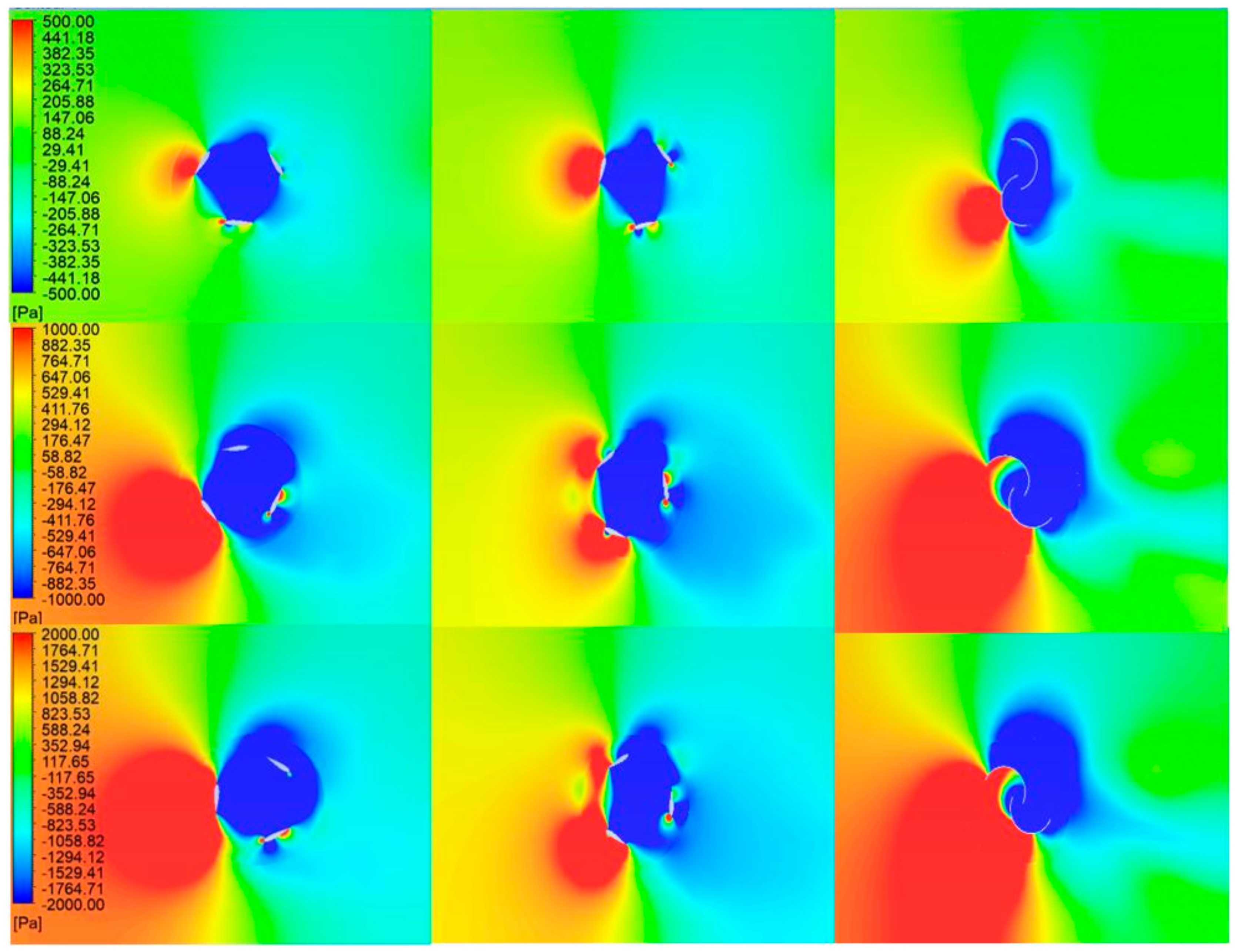
Figure 9 illustrates the pressure contours of the flow surrounding the Gorlov, Darrieus, and Savonius turbines from left to right, respectively. The lowest pressure occurs on the inner surface of the Gorlov and Darrieus turbine blades and the highest pressure on the outer blades’ surface, which is directly affected by the flow. In the Savonius turbine, maximum pressure occurs on the convex blade, which is directly influenced by the flow, and the minimum pressure occurs along this blade’s inner surface and around other blades. For Gorlov and Darrieus, the minimum pressure at the turbine center increases along the downstream in proportion to the distance away from the turbine, while in Savonius, this change occurs at a shorter distance. As the velocity increases, there is an increase in pressure values on the turbine blades that are in direct contact with the flow, resulting in the formation of pressure contours that decrease with distances on the turbine’s upstream side. On the other hand, on the downstream side, there is an increase in the distance of the minimum pressure effect along the pressure contours.
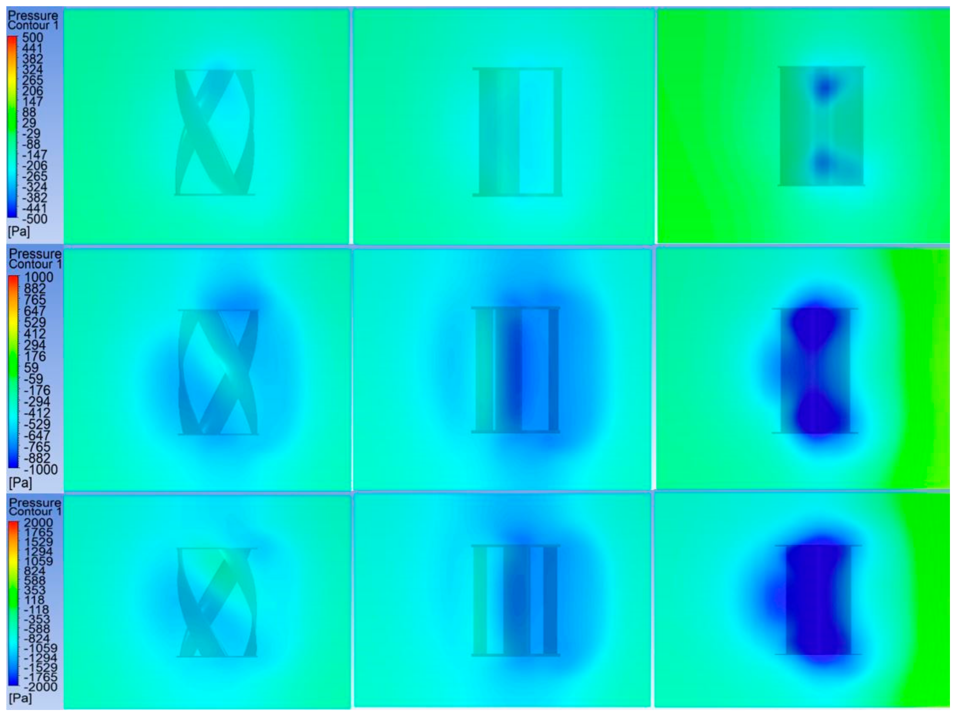
The pressure variations after 5 cm of turbines downstream are presented in Figure 10. The minimum pressure values around the turbine swept area increase with rising flow velocity, more noticeably in the drag force turbine type, Savonius.
To further examine and compare the results, variations of pressure values were plotted along the water depth for three velocities at the midpoint of the channel’s width and 5 cm downstream from the turbines in the direction of water flow (Figure 11). Here, the formation of higher negative pressure is most evident in the Savonius turbine’s surrounding flow.

5.2. Velocity Contours

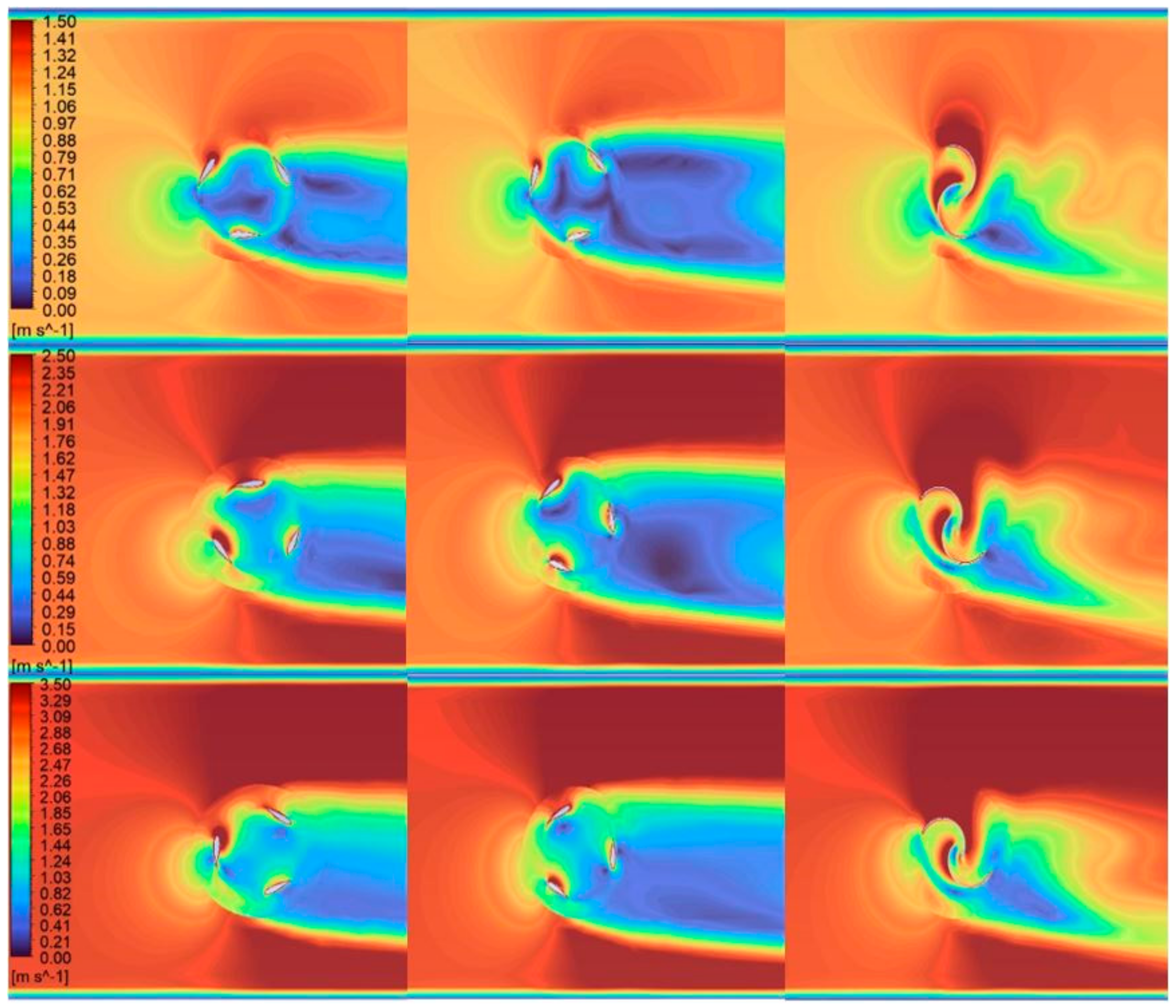
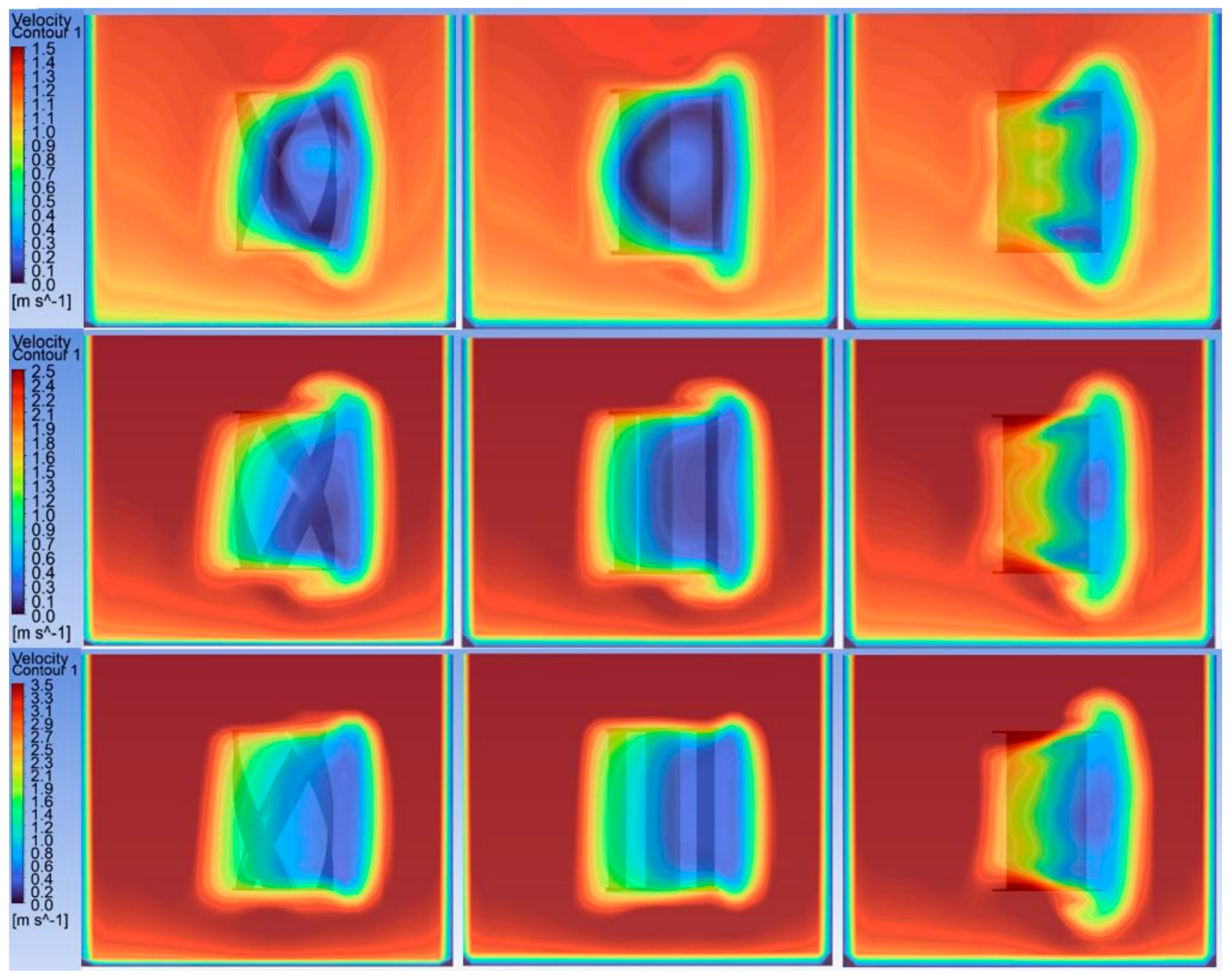
Figure 12 shows the plots of velocity contour around the turbines and flow domain for the Gorlov, Darrieus, and Savonius turbines from left to right, respectively. The velocity contour upstream of the turbine represents the inlet boundary conditions. In the vicinity of the turbine, its rotation affected the velocity.
A stagnation point is present where the kinetic energy of the free stream water is converted into potential energy upon encountering the turbine blades. This leads to variations in pressure surrounding the blade surface. The torque generated in the turbine results from the force applied to the blades due to pressure fluctuations [42]. A region of greater velocity was observed at the location of maximum relative motion between the blades and the water. A high-velocity region was observed near the leading edge of the turbine blades on the upstream side of the Gorlov and Darrieus turbine. However, a significant density of velocity vectors accumulates on the curved facet of the blade of the Savonius turbine.
The velocity variations after 5 cm of turbines downstream are presented in Figure 13. For all three types, a decrease in minimum flow velocity values (dark blue color) was observed around the turbine swept area as flow velocity increased.
Variations of velocity values were plotted along the water depth for three velocities at the midpoint of the channel’s width and 5 cm downstream from the turbines in the direction of water flow (Figure 14). At this point, the Savonius turbine was seen to have a higher velocity of the surrounding flow, especially at lower flow velocities.

5.3. Turbulence Kinetic Energy Contours

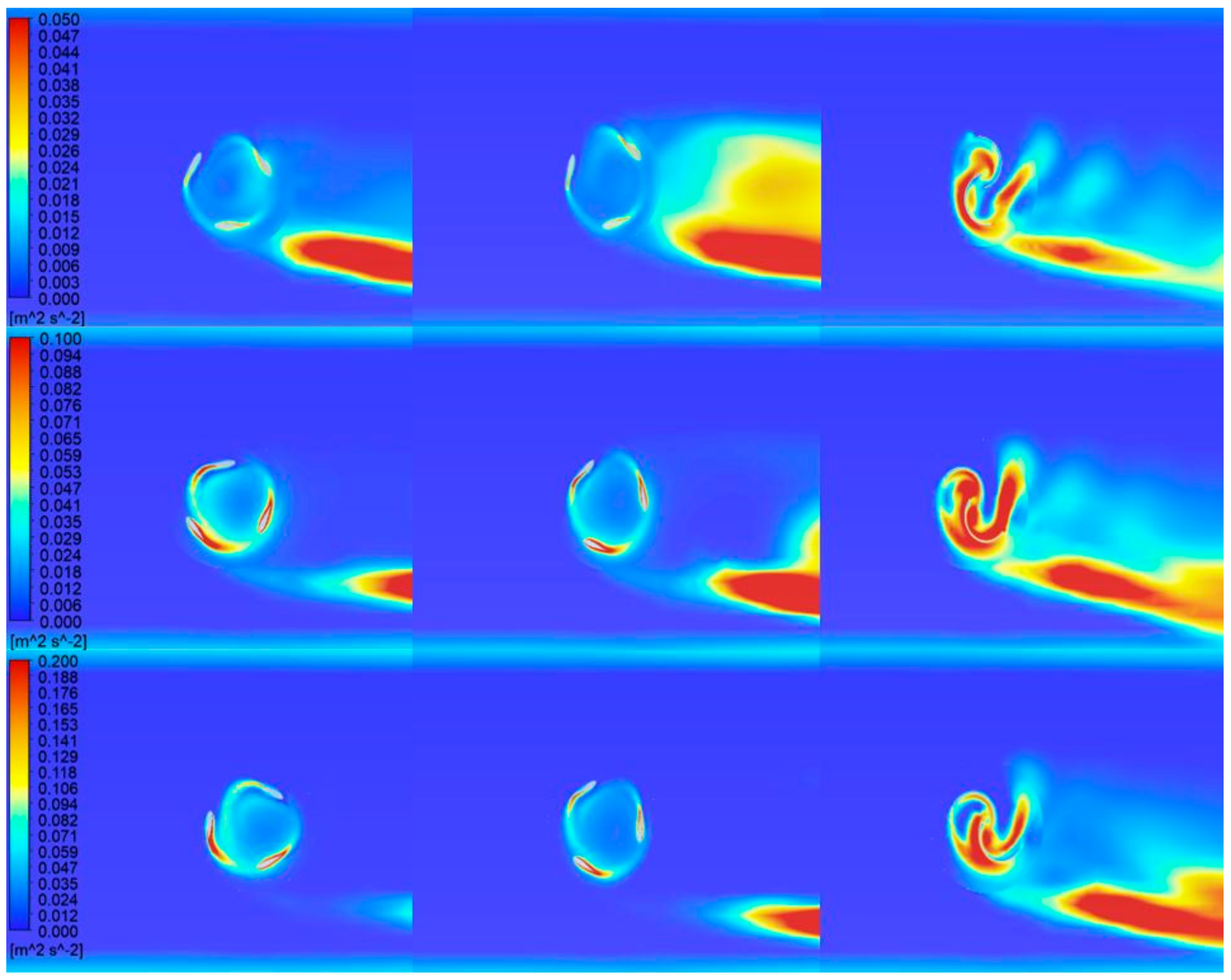
Figure 15 displays the turbulence kinetic energy contour plots around the turbines and flow domain for the Gorlov, Darrieus, and Savonius turbines from left to right, respectively. A high-turbulence region was observed at the trailing edge of the blades in the Gorlov and Darrieus turbines. Savonius reached the maximum turbulence kinetic energy value at a velocity of 3 m/s, reaching the minimum CP peak value (Figure 8). The maximum turbulence kinetic energy value increases with greater flow velocity in all turbine modeling.
The turbulence kinetic energy variations after 5 cm of turbines downstream are presented in Figure 16.
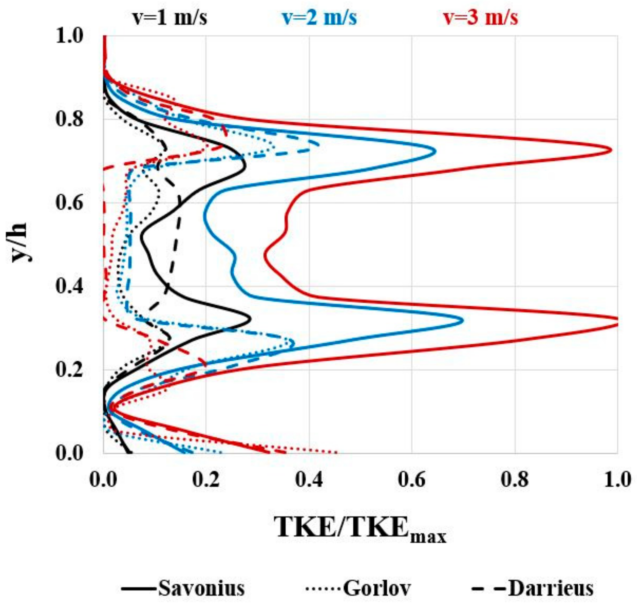
Variations of turbulence kinetic energy values were plotted along the water depth for three velocities at the midpoint of the channel’s width and 5 cm downstream from the turbines in the direction of water flow (Figure 17). Here, the formation of turbulence kinetic energy in the flow surrounding the Savonius turbine suggests that a significant portion of energy is lost to this flow, providing an explanation for this turbine’s comparatively lower efficiency values.
As seen in Figure 18, Savonius turbine torque generation is initially high; Darrieus shows apparent fluctuations, while Gorlov appears more stable. The Savonius turbine’s self-starting capacity is significantly higher than the other two, especially that of the Darrieus. Self-starting capacity is not available in areas with negative torque on the chart. While the highest torque values were achieved by the Savonius turbine, the highest values in turbine rotation (RPM) were for Darrieus, followed by Gorlov and Savonius, respectively.

6. Conclusions

The present paper numerically investigates the widely used Gorlov, Darrieus, and Savonius vertical axis water turbines. Their performance was evaluated at different flow velocities and the results were used in potential hydrokinetic energy calculations. The numerical analysis was conducted in 3D using the ANSYS Fluent. Using computational fluid dynamics software, Semi-Implicit Method for Pressure-Linked Equations (SIMPLE) was applied with an SST k-ω turbulence model. The three-dimensional dynamic mesh technique was used in an attempt to capture the simulation of turbines rotating with water flow. The visualization of the flow behavior across the turbine involved the analysis and examination of the pressure, velocity, and turbulence kinetic energy contours for different flow velocity conditions. The numerical study led to the following conclusions:
  • The maximum power coefficient value of 0.293 was obtained for the model with a Darrieus turbine corresponding to a water velocity of 3 m/s and a TSR value of 1.34.
  • The Savonius turbine achieved the lowest maximum power of coefficient value at a velocity of 3 m/s.
  • The maximum torque coefficient value obtained from the turbines is 0.419 at 0.60 TSR for 1.5 m/s water velocity, achieved by the Savonius turbine.
  • The Darrieus and Gorlov turbines were found to have a more comprehensive operating range than Savonius.
  • The minimum pressure values around the Savonius turbine swept area increase with higher flow velocities and are observed in the turbine downstream.
  • The Savonius blade exhibited the most effective self-starting capability.
  • It is essential to use the dynamic mesh technique for optimal turbine rotation display in 3D modeling.
  • Simulated flow around the Savonius turbine indicated a relatively higher turbulent flow, resulting in increased energy dissipation downstream.
  • The straight blade (Darrieus) turbine performed better than the helical blade (Gorlov).
  • Hydrokinetic turbines can produce significant energy even in water depths as low as 40 cm and, therefore, have great potential as a renewable energy source.
The numerical results obtained from this current study have the potential to guide future studies aimed at evaluating the effect of sediment transport on vertical axis water turbine blades in river flow. This study is limited to numerical simulations using CFD software and lacks experimental validation and, thus, the accuracy of the results may be affected by the assumptions and simplifications made in the simulations. The research focuses on evaluating the turbine efficiency for specific design parameters and between 0.5 and 3 m/s velocity values in the identical conditions and the results may not apply to different velocities and turbine geometries.

Author Contributions

Conceptualization, D.K. and S.E.; Formal analysis, D.K.; Methodology, D.K., A.B. and S.E.; Visualization, D.K., A.B. and S.E.; Writing—original draft, D.K.; Writing—review and editing, A.B. and S.E.; Supervision, S.E. All authors have read and agreed to the published version of the manuscript.

Funding

This research received no external funding.

Data Availability Statement

Data are contained within the article.

Acknowledgments

The authors would like to thank Simon Edward Mumford for his help with language editing and proofreading.

Conflicts of Interest

The authors declare no conflicts of interest.

References

  1. Ellabban, O.; Abu-Rub, H.; Blaabjerg, F. Renewable energy resources: Current status, future prospects and their enabling technology. Renew. Sustain. Energy Rev. 2014, 39, 748–764. [Google Scholar] [CrossRef]
  2. REN21. Renewables 2020 Global Status Report. 2020. p. 367. Available online: https://www.ren21.net/wp-content/uploads/2019/05/gsr_2020_full_report_en.pdf (accessed on 21 November 2023).
  3. Singh, D.; Power, M.H. Resource Assessment Handbook; Asian and Pacific Centre for Transfer of Technology of the United Nations, Economic and Social Commission for Asia and the Pacific (ESCAP): New Delhi, India, 2009; pp. 16–34. [Google Scholar]
  4. Hoq, T.; Nawshad, U.A.; Islam, N.; Syfullah, K.; Rahman, R. Micro hydro power: Promising solution for off-grid renewable energy source. Int. J. Sci. Eng. Res. 2011, 2, 2–6. [Google Scholar]
  5. Ashok, S. Optimised model for community-based hybrid energy system. Renew. Energy 2007, 32, 1155–1164. [Google Scholar] [CrossRef]
  6. Paish, O. Small hydro power: Technology and current status. Renew. Sustain. Energy Rev. 2002, 6, 537–556. [Google Scholar] [CrossRef]
  7. Vermaak, H.J.; Kusakana, K.; Koko, S.P. Status of micro-hydrokinetic river technology in rural applications: A review of literature. Renew. Sustain. Energy Rev. 2014, 29, 625–633. [Google Scholar] [CrossRef]
  8. Khan, M.J.; Iqbal, M.T.; Quaicoe, J.E. River current energy conversion systems: Progress, prospects and challenges. Renew. Sustain. Energy Rev. 2008, 12, 2177–2193. [Google Scholar] [CrossRef]
  9. Grabbe, M.; Yuen, K.; Goude, A.; Lalander, E.; Leijon, M. Design of an experimental setup for hydro-kinetic energy conversion. Int. J. Hydropower Dams 2009, 16, 112–116. [Google Scholar]
  10. Kuschke, M.; Strunz, K. Modeling of tidal energy conversion systems for smart grid operation. In Proceedings of the 2011 IEEE Power and Energy Society General Meeting, Detroit, MI, USA, 24–28 July 2011; pp. 1–3. [Google Scholar]
  11. Cada, G.; Ahlgrimm, J.; Bahleda, M.; Bigford, T.; Stavrakas, S.D.; Hall, D.; Moursund, R.; Sale, M. Potential impacts of hydrokinetic and wave energy conversion technologies on aquatic environments. Fisheries 2007, 32, 174–181. [Google Scholar] [CrossRef]
  12. Van Arkel, R.; Owen, L.; Allison, S.; Tryfonas, T.; Winter, A.; Entwistle, R.; Keane, E.; Parr, J. Design and preliminary testing of a novel concept low depth hydropower device. In Proceedings of the OCEANS’11 MTS/IEEE KONA, Waikoloa, HI, USA, 19–22 September 2011; pp. 1–10. [Google Scholar]
  13. Hermann, S. Design of a Micro-Hydro Powered Battery Charging System for Rural Village Electrification; Carl von Ossietzky University: Oldenburg, Germany, 2006. [Google Scholar]
  14. Elghali, S.B.; Benbouzid, M.E.H.; Charpentier, J.F. Marine tidal current electric power generation technology: State of the art and current status. In Proceedings of the 2007 IEEE International Electric Machines and Drives Conference, Antalya, Turkey, 3–5 May 2007; Volume 2, pp. 1407–1412. [Google Scholar]
  15. Johnson, J.B.; Pride, D.J. River, Tidal, and Ocean Current Hydrokinetic Energy Technologies: Status and Future Opportunities in Alaska; Alaska Center for Energy and Power: Fairbanks, AK, USA, 2010. [Google Scholar]
  16. Kusakana, K.; Vermaak, H.J. Hydrokinetic power generation for rural electricity supply: Case of South Africa. Renew. Energy 2013, 55, 467–473. [Google Scholar] [CrossRef]
  17. Lago, L.I.; Ponta, F.L.; Chen, L. Advances and trends in hydrokinetic turbine systems. Energy Sustain. Dev. 2010, 14, 287–296. [Google Scholar] [CrossRef]
  18. Güney, M.S.; Kaygusuz, K. Hydrokinetic energy conversion systems: A technology status review. Renew. Sustain. Energy Rev. 2010, 14, 2996–3004. [Google Scholar] [CrossRef]
  19. Kumar, A.; Nikhade, A. Hybrid kinetic turbine rotors: A review. Int. J. Eng. Sci. Adv. Technol. 2014, 4, 453–463. [Google Scholar]
  20. Kumar, D.; Sarkar, S. A review on the technology, performance, design optimization, reliability, techno-economics and environmental impacts of hydrokinetic energy conversion systems. Renew. Sustain. Energy Rev. 2016, 58, 796–813. [Google Scholar] [CrossRef]
  21. Niebuhr, C.M.; Van Dijk, M.; Neary, V.S.; Bhagwan, J.N. A review of hydrokinetic turbines and enhancement techniques for canal installations: Technology, applicability and potential. Renew. Sustain. Energy Rev. 2019, 113, 109240. [Google Scholar] [CrossRef]
  22. Saini, G.; Saini, R.P. A review on technology, configurations, and performance of cross-flow hydrokinetic turbines. Int. J. Energy Res. 2019, 43, 6639–6679. [Google Scholar] [CrossRef]
  23. Sood, M.; Singal, S.K. Development of hydrokinetic energy technology: A review. Int. J. Energy Res. 2019, 43, 5552–5571. [Google Scholar] [CrossRef]
  24. Ibrahim, W.I.; Mohamed, M.R.; Ismail, R.M.T.R.; Leung, P.K.; Xing, W.W.; Shah, A.A. Hydrokinetic energy harnessing technologies: A review. Energy Rep. 2021, 7, 2021–2042. [Google Scholar] [CrossRef]
  25. Kamal, M.M.; Saini, R.P. A review on modifications and performance assessment techniques in cross-flow hydrokinetic system. Sustain. Energy Technol. Assess. 2022, 51, 101933. [Google Scholar] [CrossRef]
  26. Li, L.; Xu, W.; Tan, Y.; Yang, Y.; Yang, J.; Tan, D. Fluid-induced vibration evolution mechanism of multiphase free sink vortex and the multi-source vibration sensing method. Mech. Syst. Signal Process. 2023, 189, 110058. [Google Scholar] [CrossRef]
  27. Li, L.; Li, Q.; Ni, Y.; Wang, C.; Tan, Y.; Tan, D. Critical penetrating vibration evolution behaviors of the gas-liquid coupled vortex flow. Energy 2024, 292, 130236. [Google Scholar] [CrossRef]
  28. Shiono, M.; Suzuki, K.; Kiho, S. Output characteristics of Darrieus water turbine with helical blades for tidal current generations. In Proceedings of the ISOPE International Ocean and Polar Engineering Conference, Kitakyushu, Japan, 26–31 May 2002; p. ISOPE-I. [Google Scholar]
  29. Niblick, A.L. Experimental and Analytical Study of Helical Cross-Flow Turbines for a Tidal Micropower Generation System; University of Washington: Seattle, WA, USA, 2012. [Google Scholar]
  30. Yang, B.; Shu, X.W. Hydrofoil optimization and experimental validation in helical vertical axis turbine for power generation from marine current. Ocean Eng. 2012, 42, 35–46. [Google Scholar] [CrossRef]
  31. Wenlong, T.; Baowei, S.; Zhaoyong, M. Conceptual design and numerical simulations of a vertical axis water turbine used for underwater mooring platforms. Int. J. Nav. Archit. Ocean Eng. 2013, 5, 625–634. [Google Scholar] [CrossRef]
  32. Sahim, K.; Santoso, D.; Radentan, A. Performance of combined water turbine with semielliptic section of the Savonius rotor. Int. J. Rotating Mach. 2013, 2013, 985943. [Google Scholar] [CrossRef]
  33. Demircan, E. Design and Analysis of a Vertical Axis Water Turbine for River Applications Using Computational Fluid Dynamics. Master’s Thesis, Middle East Technical University, Ankara, Türkiye, 2014. [Google Scholar]
  34. Bachant, P.; Wosnik, M. Performance measurements of cylindrical-and spherical-helical cross-flow marine hydrokinetic turbines, with estimates of exergy efficiency. Renew. Energy 2015, 74, 318–325. [Google Scholar] [CrossRef]
  35. Kumar, A.; Saini, R.P. Performance analysis of a Savonius hydrokinetic turbine having twisted blades. Renew. Energy 2017, 108, 502–522. [Google Scholar] [CrossRef]
  36. Basumatary, M.; Biswas, A.; Misra, R.D. CFD analysis of an innovative combined lift and drag (CLD) based modified Savonius water turbine. Energy Convers. Manag. 2018, 174, 72–87. [Google Scholar] [CrossRef]
  37. Saini, G.; Saini, R.P. A numerical analysis to study the effect of radius ratio and attachment angle on hybrid hydrokinetic turbine performance. Energy Sustain. Dev. 2018, 47, 94–106. [Google Scholar] [CrossRef]
  38. Mejia, O.D.L.; Quiñones, J.J.; Laín, S. RANS and hybrid RANS-LES simulations of an H-type Darrieus vertical axis water turbine. Energies 2018, 11, 2348. [Google Scholar] [CrossRef]
  39. Mosbahi, M.; Ayadi, A.; Chouaibi, Y.; Driss, Z.; Tucciarelli, T. Performance study of a Helical Savonius hydrokinetic turbine with a new deflector system design. Energy Convers. Manag. 2019, 194, 55–74. [Google Scholar] [CrossRef]
  40. Alizadeh, H.; Jahangir, M.H.; Ghasempour, R. CFD-based improvement of Savonius type hydrokinetic turbine using optimized barrier at the low-speed flows. Ocean Eng. 2020, 202, 107178. [Google Scholar] [CrossRef]
  41. Saini, G.; Saini, R.P. A computational investigation to analyze the effects of different rotor parameters on hybrid hydrokinetic turbine performance. Ocean Eng. 2020, 199, 107019. [Google Scholar] [CrossRef]
  42. Kumar, R.; Sarkar, S. Effect of design parameters on the performance of helical Darrieus hydrokinetic turbines. Renew. Sustain. Energy Rev. 2022, 162, 112431. [Google Scholar] [CrossRef]
  43. Khan, M.J.; Bhuyan, G.; Iqbal, M.T.; Quaicoe, J.E. Hydrokinetic energy conversion systems and assessment of horizontal and vertical axis turbines for river and tidal applications: A technology status review. Appl. Energy 2009, 86, 1823–1835. [Google Scholar] [CrossRef]
  44. Kumar, A.; Saini, R.P. Performance parameters of Savonius type hydrokinetic turbine—A Review. Renew. Sustain. Energy Rev. 2016, 64, 289–310. [Google Scholar] [CrossRef]
  45. Maldar, N.R.; Ng, C.Y.; Oguz, E. A review of the optimization studies for Savonius turbine considering hydrokinetic applications. Energy Convers. Manag. 2020, 226, 113495. [Google Scholar] [CrossRef]
  46. Talukdar, P.K.; Sardar, A.; Kulkarni, V.; Saha, U.K. Parametric analysis of model Savonius hydrokinetic turbines through experimental and computational investigations. Energy Convers. Manag. 2018, 158, 36–49. [Google Scholar] [CrossRef]
  47. Guo, F.; Song, B.; Mao, Z.; Tian, W. Experimental and numerical validation of the influence on Savonius turbine caused by rear deflector. Energy 2020, 196, 117132. [Google Scholar] [CrossRef]
  48. Ramadan, A.; Hemida, M.; Abdel-Fadeel, W.A.; Aissa, W.A.; Mohamed, M.H. Comprehensive experimental and numerical assessment of a drag turbine for river hydrokinetic energy conversion. Ocean Eng. 2021, 227, 108587. [Google Scholar] [CrossRef]
  49. Mohamed, M.H. Performance investigation of H-rotor Darrieus turbine with new airfoil shapes. Energy 2012, 47, 522–530. [Google Scholar] [CrossRef]
  50. Alqurashi, F.; Mohamed, M.H. Aerodynamic forces affecting the H-rotor Darrieus wind turbine. Model. Simul. Eng. 2020, 2020, 1368369. [Google Scholar] [CrossRef]
  51. Dominy, R.; Lunt, P.; Bickerdyke, A.; Dominy, J. Self-starting capability of a Darrieus turbine. Proc. Inst. Mech. Eng. Part A J. Power Energy 2007, 221, 111–120. [Google Scholar] [CrossRef]
  52. Hill, N.; Dominy, R.; Ingram, G.; Dominy, J. Darrieus turbines: The physics of self-starting. Proc. Inst. Mech. Eng. Part A J. Power Energy 2009, 223, 21–29. [Google Scholar] [CrossRef]
  53. Douak, M.; Aouachria, Z.; Rabehi, R.; Allam, N. Wind energy systems: Analysis of the self-starting physics of vertical axis wind turbine. Renew. Sustain. Energy Rev. 2018, 81, 1602–1610. [Google Scholar] [CrossRef]
  54. Menet, J.L. A double-step Savonius rotor for local production of electricity: A design study. Renew. Energy 2004, 29, 1843–1862. [Google Scholar] [CrossRef]
  55. Khan, M.N.I.; Iqbal, M.T.; Hinchey, M. Sea-floor power generation system. In Proceedings of the 17th IEEE NECEC Conference, St. John’s, NL, Canada, 8 November 2007. [Google Scholar]
  56. Alam, M.J.; Iqbal, M.T. Design and development of hybrid vertical axis turbine. In Proceedings of the 2009 Canadian Conference on Electrical and Computer Engineering, St. John’s, NL, Canada, 3–6 May 2009; pp. 1178–1183. [Google Scholar]
  57. Anyi, M.; Kirke, B. Hydrokinetic turbine blades: Design and local construction techniques for remote communities. Energy Sustain. Dev. 2011, 15, 223–230. [Google Scholar] [CrossRef]
  58. Jin, X.; Zhao, G.; Gao, K.; Ju, W. Darrieus vertical axis wind turbine: Basic research methods. Renew. Sustain. Energy Rev. 2015, 42, 212–225. [Google Scholar] [CrossRef]
  59. Marsh, P.; Ranmuthugala, D.; Penesis, I.; Thomas, G. Three-dimensional numerical simulations of straight-bladed vertical axis tidal turbines investigating power output, torque ripple and mounting forces. Renew. Energy 2015, 83, 67–77. [Google Scholar] [CrossRef]
  60. Rogowski, K. CFD Computation of the H-Darrieus wind turbine—The impact of the rotating shaft on the rotor performance. Energies 2019, 12, 2506. [Google Scholar] [CrossRef]
  61. Patel, V.; Patel, R. Free energy-extraction using Savonius hydrokinetic rotor with dual splitters. Mater. Today Proc. 2021, 45, 5354–5361. [Google Scholar] [CrossRef]
  62. Balduzzi, F.; Bianchini, A.; Maleci, R.; Ferrara, G.; Ferrari, L. Critical issues in the CFD simulation of Darrieus wind turbines. Renew. Energy 2016, 85, 419–435. [Google Scholar] [CrossRef]
  63. Rezaeiha, A.; Kalkman, I.; Blocken, B. CFD simulation of a vertical axis wind turbine operating at a moderate tip speed ratio: Guidelines for minimum domain size and azimuthal increment. Renew. Energy 2017, 107, 373–385. [Google Scholar] [CrossRef]
  64. Kamal, M.M.; Saini, R.P. A numerical investigation on the influence of savonius blade helicity on the performance characteristics of hybrid cross-flow hydrokinetic turbine. Renew. Energy 2022, 190, 788–804. [Google Scholar] [CrossRef]
  65. Ansys Fluent. ANSYS Fluent UDF Manual; ANSYS Inc.: Canonsburg, PA, USA, 2015. [Google Scholar]
  66. Marsh, P.; Ranmuthugala, D.; Penesis, I.; Thomas, G. The influence of turbulence model and two and three-dimensional domain selection on the simulated performance characteristics of vertical axis tidal turbines. Renew. Energy 2017, 105, 106–116. [Google Scholar] [CrossRef]
  67. ANSYS Inc. ANSYS Fluent Tutorial Guide R18; ANSYS Inc.: Canonsburg, PA, USA, 2018. [Google Scholar]
  68. Maître, T.; Amet, E.; Pellone, C. Modeling of the flow in a Darrieus water turbine: Wall grid refinement analysis and comparison with experiments. Renew. Energy 2013, 51, 497–512. [Google Scholar] [CrossRef]
  69. Saini, G.; Saini, R.P. Numerical investigations on hybrid hydrokinetic turbine for electrification in remote area. In Proceedings of the All India Seminar on Renewable Energy for Sustainable Development (Institution of Engineers), Ghaziabad, India, 27–28 July 2018; pp. 27–28. [Google Scholar]
  70. Cavagnaro, R.J.; Polagye, B. Field performance assessment of a hydrokinetic turbine. Int. J. Mar. Energy 2016, 14, 125–142. [Google Scholar] [CrossRef]
  71. National Energy Action. Electricity Consumption around the Home: A Simple Guide to Understanding the Typical Usage of Electrical Appliances and Equipment in the Home. 2022. Available online: https://www.nea.org.uk/wp-content/uploads/2022/03/Electricity-Consumption-Around-the-Home.pdf (accessed on 18 February 2024).
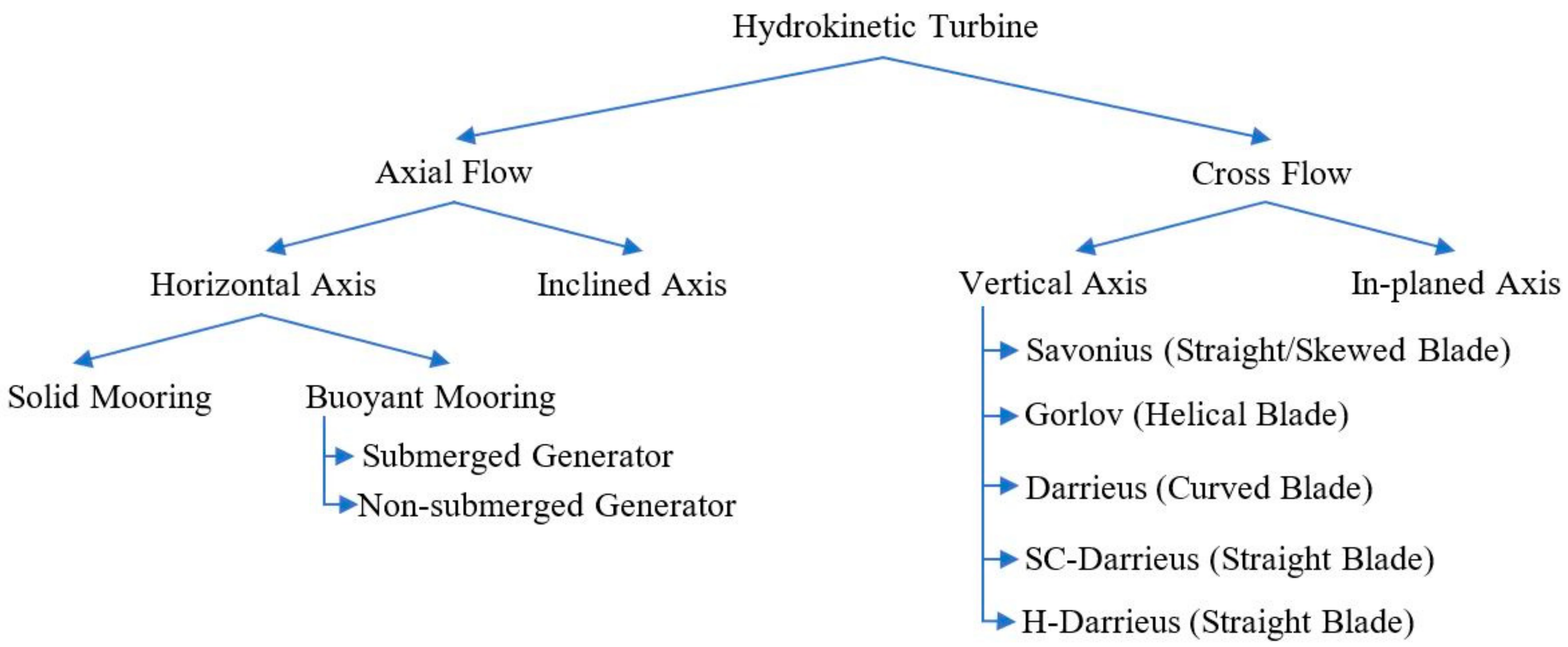
Figure 1. Hydrokinetic turbines classification (adapted from Khan et al. [43]).
Energies 17 01398 g001
Figure 2. Three-dimensional drawings of Gorlov (a), Darrieus (b), and Savonius (c) turbines.
Energies 17 01398 g002
Figure 3. Three-dimensional model domain area and boundary conditions.
Energies 17 01398 g003
Figure 4. Velocity profile, defined as inlet boundary condition.
Energies 17 01398 g004
Figure 5. Rotation turbine and its surrounding mesh in the channel are replaced by (a) Gorlov, (b) Darrieus, and (c) Savonius turbines during the analysis of each turbine.
Energies 17 01398 g005
Figure 6. Variation in angular velocity of turbines at flow velocity 2 m/s.
Energies 17 01398 g006
Figure 7. Variation of turbines CP and CT with tip speed ratio for six different velocity values.
Energies 17 01398 g007
Figure 8. Comparison of turbine CP and CT values for three different velocity values.
Energies 17 01398 g008
Figure 9. Top views of pressure distribution from the model domain (Gorlov, Darrieus, and Savonius turbines from left to right, respectively) for various velocities (1 m/s, 2 m/s, and 3 m/s from top to bottom, respectively).
Energies 17 01398 g009
Figure 10. Pressure distribution after 5 cm of turbines (Gorlov, Darrieus, and Savonius turbines from left to right, respectively) for various velocities (1 m/s, 2 m/s, and 3 m/s from top to bottom, respectively).
Energies 17 01398 g010
Figure 11. Variation of pressure values 5 cm after turbine throughout channel depth.
Energies 17 01398 g011
Figure 12. Top views of velocity distribution from the model domain (Gorlov, Darrieus, and Savonius turbines from left to right, respectively) for various velocities (1 m/s, 2 m/s, and 3 m/s from top to bottom, respectively).
Energies 17 01398 g012
Figure 13. Velocity distribution after 5 cm of turbines (Gorlov, Darrieus, and Savonius turbines from left to right, respectively) for various velocities (1 m/s, 2 m/s, and 3 m/s from top to bottom, respectively).
Energies 17 01398 g013
Figure 14. Variation of velocity values 5 cm after turbine throughout channel depth.
Energies 17 01398 g014
Figure 15. Top views of turbulence kinetic energy distribution from the model domain (Gorlov, Darrieus, and Savonius turbines from left to right, respectively) for various velocities (1 m/s, 2 m/s, and 3 m/s from top to bottom, respectively).
Energies 17 01398 g015
Figure 16. Turbulence kinetic energy distribution after 5 cm of turbines (Gorlov, Darrieus, and Savonius turbines from left to right, respectively) for various velocities (1 m/s, 2 m/s, and 3 m/s from top to bottom, respectively).
Energies 17 01398 g016
Figure 17. Variation of turbulence kinetic energy values 5 cm after turbine throughout channel depth.
Energies 17 01398 g017
Figure 18. Torque fluctuations graphs of turbines for v = 1 m/s velocity.
Energies 17 01398 g018
Table 1. The studies conducted by numerous researchers.
AuthorsTurbine
Type
MethodologyTurbine
Properties
Flow
Velocity
(m/s)
Turbulence ModelExperimental
Technique and
Channel Size
Max. CP Value Achieved
Shiono et al. [28]Helical
Darrieus
ExperimentalD = 300, H = 300
c = 62.8, 94.2, 125.7, 157.1
0.6, 1.0, and 1.4-Tow tank method
W = 3, Hw = 1.5, L = 30
≈0.35
Niblick [29]GorlovExperimentalD = 172, H = 234 0.8-Tow tank method
W = 0.757, Hw = 0.47, L = 3
0.24
Yang and Shu [30]GorlovExperimental and NumericalD = 300, H = 400, c = 90 0.5, 1.0, and 1.5SST k-ωW = 1.450, Hw = 1.4500.416
Wenlong et al. [31]DarrieusNumericalD = 1220, 1600, and 2000
H = 1000, c = 150
0.5Standard k-ε-0.1
Sahim et al. [32]Hybrid
Darrieus–Savonius
ExperimentalDarrieus
D = 300, H = 300, c = 63
Savonius
D = 30, H = 240
0.61-Irrigation canal
W = 1, Hw = 0.6
0.12
Demircan [33]DarrieusNumericalD = 175, H = 175, c = 32, d = 22 2.8SST k-ω-≈0.35
Bachant and Wosnik [34]GorlovExperimentalD = 1000, H = 13200.5–1.5-Tow tank method
W = 3.66, Hw = 2.44, L = 36.6
0.35
Kumar and Saini [35]Savonius NumericalD = 160, H = 253 0.5–2Realizable k-ε-0.39
Basumatary et al. [36]Savonius NumericalD = 260, d = 14 0.3–0.9SST k-ω-0.284
Saini and Saini [37]Hybrid
Darrieus–Savonius
NumericalDarrieus
D = 1500, c = 220
Savonius
D = 300
0.5–2.5Realizable k-ε-0.34
Mejia et al. [38]DarrieusNumericalD = 175, H = 175, c = 32, d = 22 2.8SST k-ω-0.457
Mosbahi et al. [39]Helical SavoniusExperimental and NumericalD = 182, H = 160, d = 100.86Realizable k-εİrrigation channel
W = 0.6, Hw = 0.5
0.125
Alizadeh et al. [40]Savonius NumericalD = 970, H = 10000.48SST Transition-0.29
Saini and Saini [41]Hybrid
Darrieus–Savonius
NumericalDarrieus
D = 175, H = 160, c = 55
Savonius
H = 160
0.5–2.0RNG k-ε -0.109
Kumar and Sarkar [42]Helical
Darrieus
Experimental and NumericalD = 200, H = 200 0.5SST k-ωTow tank method
W = 0.6, Hw = 0.7, L = 6
0.316
Table 2. Comparison of axial and crossflow turbines.
General CharacteristicsAxial FlowCross Flow
EfficiencyHighLow
Self-starting capabilityHaveDepends on rotor type
Debris controlHighly effectedLess effected
Airfoil requirementYesNo
Manufacturing costHighLow
Torque produceStableFluctuating
Depth requirementHighLow
Rotor shapeCircular discCylindrical
Power transmissionComplexSimple
ApplicationOcean and tidal currentsRiver currents
Table 3. Details of geometrical parameters of the turbines used in the study.
ParametersGorlovDarrieusSavonius
Turbine height, H200 mm200 mm200 mm
Turbine diameter, D150 mm150 mm150 mm
Aspect ratio, AR1.331.331.33
Shaft diameter, d12 mm12 mm12 mm
Solidity, σ0.350.32-
Blade number, n3 3 2
Length of chord, c50 mm50 mm-
AirfoilS-1046 S-1046 -
Rotor typeHelical bladeStraight bladeSemi-circular
Overlap ratio, β --0.256
Blockage ratio, BR0.1360.1360.136
Blade inclination angle, φ (deg)43.7 --
Overlap distance--22 mm
Blade diameter --86 mm
Table 4. Detail of boundary conditions.
LocationBoundary ConditionValue
Inlet VelocityVelocity profile with UDF
Outlet Pressure1 atm
Bottom and side walls No-slip walls-
Top surface Symmetry -
TurbineNo-slip wallsVariable depending on flow conditions
Table 5. Details of the refinement levels for turbine meshing.
Refinement
Level
Number of ElementsNumber of NodesQuality Aspects (Average)Mesh Size (mm)CP
SkewnessOrthogonal QualityAspect RatioRotating PartStationary Part
Gorlov
1333,189186,7080.150.861.9110200.054
2421,726279,5180.130.891.7010150.079
3745,051341,2020.170.841.7610150.118
4812,752215,9580.220.791.8812200.204
5880,997283,7370.200.801.8710200.199
61,050,528315,3110.210.801.8610200.184
71,259,805350,8620.210.791.8610200.197
81,467,147633,0130.170.842.006150.177
91,760,138773,0860.170.842.095150.178
102,207,1721,129,4300.160.861.806100.177
Darrieus
1325,272183,4110.150.861.9210200.120
2418,465280,8090.120.891.6910150.120
3619,392181,6330.230.791.8912250.201
4688,167249,6040.190.811.8810200.190
5751,805343,6360.170.841.7610150.192
6888,048268,2200.210.801.8510200.209
7921,690292,0020.210.801.8710200.204
81,101,723574,0580.150.862.056150.179
91,342,820615,3330.170.842.016150.211
101,470,951638,7380.170.842.006150.192
Savonius
1375,180193,7330.160.851.9110200.157
2464,396287,0570.220.791.7110250.252
3717,770240,6030.200.801.8510200.269
4805,740351,7390.180.831.7710150.268
5826,944354,9910.180.831.7710150.268
61,101,456273,3900.220.781.8710250.276
71,156,280332,1710.210.791.8710200.276
81,248,353427,5770.200.811.7910150.276
91,464,115726,1200.150.862.145150.272
101,765,381690,3700.180.821.986150.271
Bold font denotes selected mesh configuration for each turbine.
Table 6. Details of the numerical modeling parameters.
SettingsParameter
Water density 1000 kg/m3
Water viscosity 0.001002 kg/m.s
Water velocity0.5–3 m/s
Turbulent modelSST k-ω
Pressure–velocity coupling SIMPLE
Convergence criteria10−5
Output frequencyEvery time step
Time step size 0.01 s
Table 7. Maximum power harvested from the turbines under three different flow conditions.
Maximum Power Harvested (Watts)
v = 1 m/sv = 2 m/sv = 3 m/s
Gorlov3.5226.3993.9
Darrieus4.3333.78118.64
Savonius4.1429.8198.55
Disclaimer/Publisher’s Note: The statements, opinions and data contained in all publications are solely those of the individual author(s) and contributor(s) and not of MDPI and/or the editor(s). MDPI and/or the editor(s) disclaim responsibility for any injury to people or property resulting from any ideas, methods, instructions or products referred to in the content.