Article

Conditions That Determine Changing the Function of Mine Shafts in a Gassy Coal Mine—A Case Study

Faculty of Civil Engineering and Resource Management, AGH University of Krakow, Mickiewicza 30 Av., 30-059 Krakow, Poland
*
Author to whom correspondence should be addressed.
Energies 2024, 17(6), 1379; https://doi.org/10.3390/en17061379
Submission received: 9 February 2024 / Revised: 5 March 2024 / Accepted: 7 March 2024 / Published: 13 March 2024
(This article belongs to the Section H: Geo-Energy)

Abstract

:
Ventilation plays a key role in ensuring safe exploitation in underground gassy mines. Over the years, the structure of a mine’s ventilation network changes. Therefore, it becomes necessary to construct new excavations, while some existing excavations lose their potential for future mining activity. Constructing new excavations, especially shafts, is very expensive. Therefore, mine operators are looking for solutions to ensure appropriate ventilation by reorganizing the ventilation network and using existing infrastructure, including shafts. This article presents the example of a coal mine located in the Upper Silesian Coal Basin in Poland to discuss the factors relevant to switching the function of one of the central shafts from a downcast function to an upcast one. This change is accompanied by the closure of a peripheral upcast shaft. The main aim of this change is to assess the possibility of further safe operation without the construction of new shafts. This action also results in the release of the coal currently closed in the pillar of the shaft being closed. Using a numerical model of the mine ventilation network allowed for the comparison of the considered solutions before making final decisions and implementing changes in the network. The calculations showed that it is possible to provide appropriate ventilation in the mine, but it would need to take into account certain technological assumptions, like the additional technical function of the changed shaft. This article discusses the advantages and disadvantages of modifications to the mine ventilation network, as well as their guiding principles, in the context of existing methane hazards. The procedure presented in this article can be adopted in other mine ventilation networks in which analogous modifications are considered.

1. Introduction

Every underground coal mine is designed in such a way as to enable reaching the desired coal output. The method of deposit opening, including the number of shafts and their functions or the number and depth of mining levels, but also the structure of primary excavations, depends on the positioning of the deposit in the mine area. Over the years, due to the gradual depletion of the deposit, new excavations are performed, and frequently shafts are deepened and new levels are opened to reach deeper coal seams. These developments cause the mine’s ventilation network and its transport methods to change. As a result, parts of the mine infrastructure become redundant and may be closed as a result. In particular, the shafts that have little potential for future extraction due to their localization, depth, technical condition, and ventilation route length offer the possibility to release the coal from their pillars. Closing a shaft, however, increases the equivalent resistance of the ventilation network and reduces the intake air flow supplied to the mine, which may have an adverse effect on the ventilation in underground excavations.
Closing a shaft and reorganizing a mine ventilation network needs to be preceded by a careful analysis. This need becomes paramount in the presence of methane hazards. If the shaft being closed has functioned as an upcast shaft (with fans), it must be replaced by another shaft to maintain the required air flow in the network. To carry out such a closure, it is possible to adapt one of the existing downcast shafts for use as an upcast one. Constructing new shafts is very expensive, so mine operators are looking for solutions to ensure appropriate ventilation by reorganizing the ventilation network and using existing infrastructure. Most often, upcast shafts do not have the characteristics for the proper ventilation of mining districts; however, the electricity consumption required for ventilation using fans increases costs.
The abovementioned problems are very rarely discussed in the literature. The most often discussed general issues are related to the management and optimization of mine ventilation (temporarily reducing air flow for reduced energy consumption and ventilation on demand). Many publications are devoted to the use of software for calculations in ventilation networks and 3D visualization. De Sousa [1] pointed out that to save on costs, modern mining operations must constantly strive toward optimizing the operating efficiency of their ventilation systems. In the article, they presented an overview of mathematical models and techniques used in computer programming and ventilation network models. They also pointed out that a calibrated model needs to be continually refined, maintained, and updated as the mine ventilation system changes in order to be acceptably used in ventilation planning exercises. Wei [2] considered using the ant colony algorithm to solve the problem of mine ventilation system optimization. He concluded that the ant colony algorithm is a very good method for solving complicated combination optimization problems. In another article, Feng et al. [3] presented the use of a 3D simulation system (VENTSIM) in mine ventilation management in the Donghai Mine. They showed that the system satisfies the requirements of mine ventilation management and provides scientific and reliable data for decision-makers, which has improved the level of mine ventilation management. Shen and Wang [4] presented an all-purpose simulation and optimization software for the mine ventilation system of an underground mine programmed with VB language, SQL Server database, and 3D drawing software (SolidWorks). They pointed out that software realizes many functions such as mine ventilation information management, ventilation system project optimization, mine ventilation 3D simulation, etc. Wallace et al. [5] in their article analyzed the state-of-the-art in ventilation addressing the trends connected with ventilation on demand, mine ventilation monitoring systems, using software for planning and predicting, energy savings regarding ventilation and air-cooling systems, and real-time monitoring. They concluded that the use of ventilation modeling software represents a significant time-saving tool and can greatly assist the ventilation engineer in developing complete and thorough designs, allowing for the rapid development of numerous permeations and design options. They also pointed out that tools available to the ventilation engineer are only as good as the project inputs developed by the engineer. Wang et al. [6] dealt with optimizing the performance of refrigeration and ventilation systems to reduce energy consumption. Zhong et al. [7] presented an efficient ventilation network solution based on minimum independent closed loops. Szlązak and Korzec [8] presented the solution for the main fan station for underground mines being decommissioned in terms of reducing energy consumption by ventilation.
There are also some publications regarding the impact of ventilation on hazards, especially methane and fire hazards. Liu et al. [9] presented a case study of an optimized intermittent ventilation strategy based on CFD modeling and the concept of frequency conversion technology. In conclusion, they stated that the conducted studies provide the possibility to design an optimized intermittent ventilation pattern with the same conception of FTC based on the spatiotemporal characteristics of air flow behavior and methane distribution. Pach et al. [10] analyzed reversal ventilation as a prevention method against fire hazards in underground mines. They also considered the occurrence of methane hazards in their research. Tutak et al. [11] presented the impact of the ventilation system on the methane release hazard and spontaneous combustion of coal in the area of exploitation. Szlazak et al. [12] presented a procedure for a coal seam exploitation design under the conditions of methane hazard.
In this article, the authors use the example of a coal mine located in the Upper Silesian Coal Basin in Poland to discuss the factors relevant to changing the function of one of the central shafts from downcast to upcast, which is accompanied by the closure of a peripheral upcast shaft. The main aim of conducting these changes in the mine ventilation network is to assess the possibility of the further safe operation of existing shafts without constructing new shafts. This action would also allow the release of the coal currently closed in the pillar of the shaft that is about to be closed. The calculations were made using a numerical model of the ventilation network and are based on Hardy Cross’s numerical method. The input data for the model of air flow distribution in the network were obtained by conducting ventilation measurements in the mine. In the mine under analysis, extracted coal seams are characterized by high methane content. The ongoing forecasts indicate that considerable methane hazards will continue in the years to come. Using a numerical model of the mine ventilation network allowed us to compare the considered solutions before making final decisions and implementing changes in the network. The calculations showed that it is possible to provide appropriate ventilation in the mine considering certain technological assumptions, especially those connected with the additional technical function of the changed shaft. This article discusses the advantages and disadvantages of modifications to the mine ventilation network, as well as their guiding principles, in the context of existing methane hazards.

2. The Characteristics of the Mine

2.1. General Information

The mine discussed in this article is located in the Upper Silesian Coal Basin (USCB) in Poland. The mine has been active for over 60 years. The area of the mine is 21.31 square kilometers. The estimated coal reserves are 185.12 million tons. The extracted coal is of the 34.2 type. The mine’s ventilation network has an active connection to the adjacent mine.
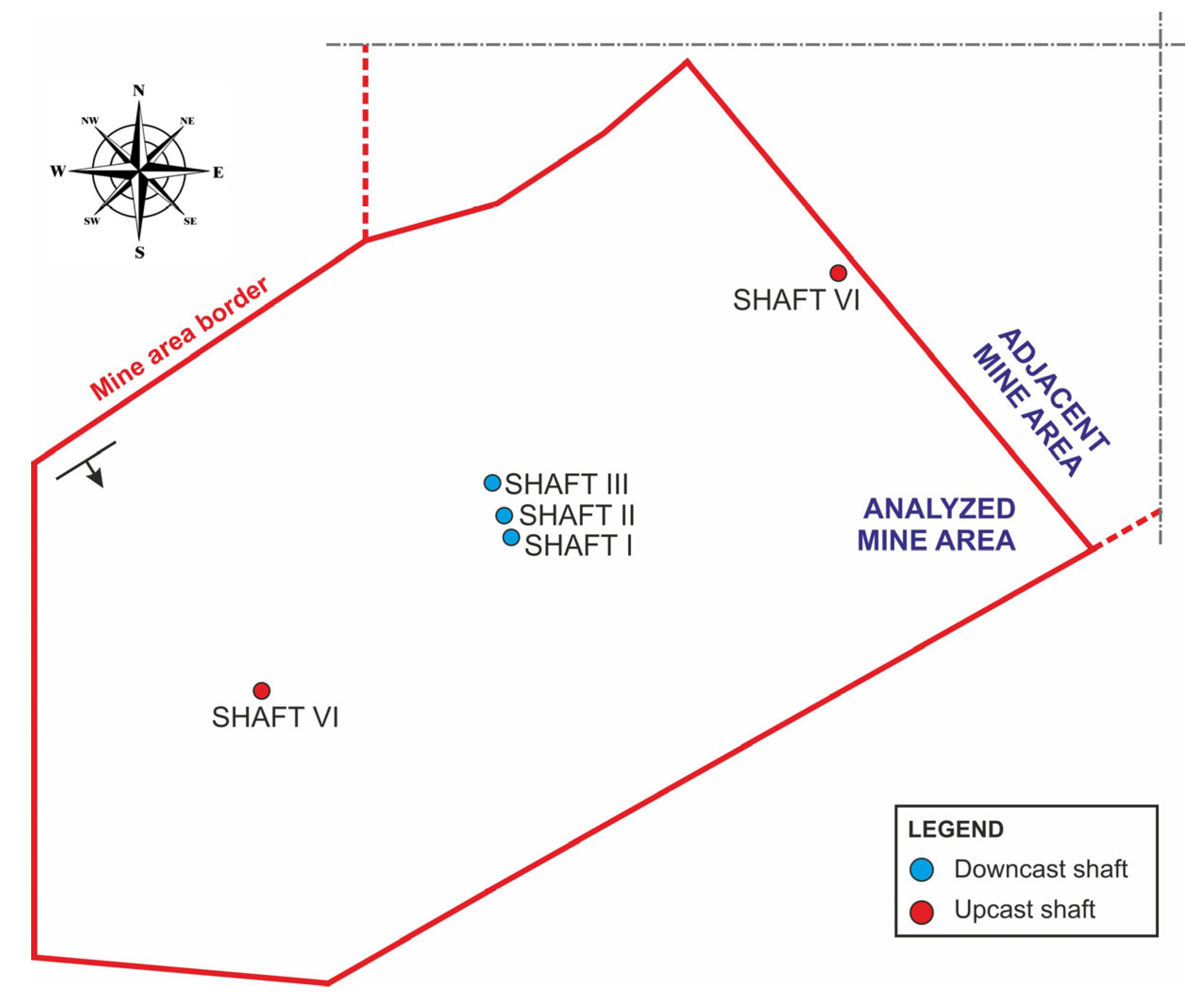
The location of the USCB in Poland and in Europe is presented in Figure 1. The mine area and the positioning of the shafts are presented in Figure 2.

2.2. The Characteristics of Natural Hazards

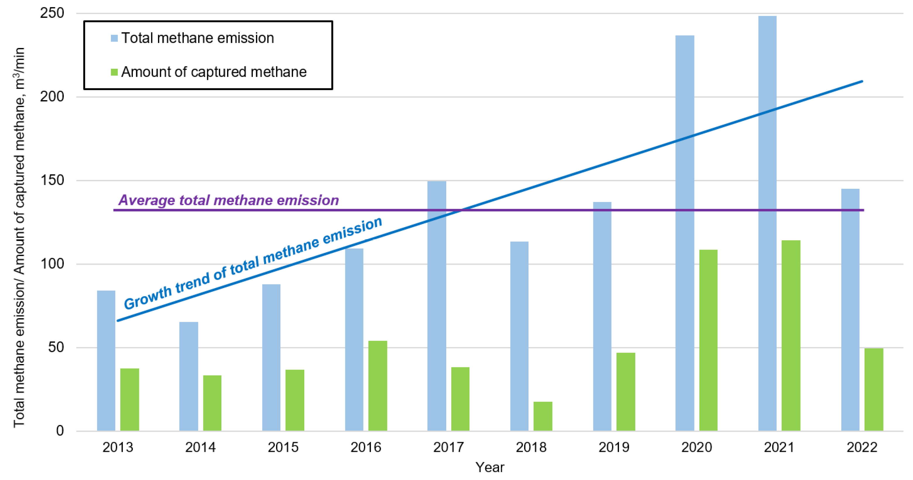
Coal is extracted from seams categorized as representing various levels of methane hazard, from I to IV [13]. The studies into the methane content of seams below the level of 650 m, where future extraction is planned, have revealed a further rise in the methane content of coal. Figure 3 presents the changes in the total methane emission and captured methane in the USCB mine from 2013–2022. During this period, the average total methane emission was 132.7 m3/min. During the period analyzed here, however, we can observe considerable increases, especially in 2020 and 2021, connected with the mining in longwalls with a very high methane emission (reaching 80 m3/min). A closer look at the entire period reveals a gradual rise in the amount of released methane caused by the increasing mined seam depth, which is characterized by higher methane content.
In addition to the methane hazard, other hazards occurred in the mine. These hazards are classified according to the Polish mining regulation as follows [13]:
  • Outbursts of gas and rocks—categories II and III (there are three categories and III is the highest category);
  • Dust coal explosion—class B (there are two classes and B is the highest class);
  • Endogenous fire hazard—groups I and II of spontaneous combustion of coal (I and II are the lowest spontaneous combustion groups in the five-level classification);
  • Climate hazard—the average virgin rock temperature is:
    Level 450 m—26.4 degrees of Celsius;
    Level 650 m—27.2 degrees of Celsius;
    Level 850 m—32.4 degrees of Celsius;
    Level 1050 m—39.7 degrees of Celsius;
  • Water hazard—I and II degrees (there are three degrees and Idegree I is the lowest level—water inflow depends on the part of the deposit);
  • Rockburst hazard—I and II degrees (there are two degrees—the level of rockburst hazard depends on mining depth and part of the deposit).

3. The Numerical Model of the Ventilation Network

3.1. Research Background

Air flow distribution in the mine ventilation networks is described by the four basic equations of fluid dynamics. There are continuity equation, movement equation, energy equation, and equation of gas state [14,15]. In most cases, one-dimensional flow is assumed for simplification.
In practice, a ventilation network is presented in a scheme composed of nodes and edges, termed junctions and branches [14,15,16,17,18,19]. Edges represent different paths of air flow, which are connected by junctions from closed paths, termed fundamental meshes. Meshes are expressed by junction–branch and mesh–junction matrixes. Junction and mesh equations, assuming a constant density of air throughout the branch i, can take the following form:
i = 1 N ε k i · V ˙ i = 0
and
i = 1 N α m i · W i p m i + h n i = 0
Each symbols are explained in the Nomenclature section at the end of the article.
Based on the second Kirchhoff’s circuit law, total pressure drop in a ventilation mesh according to Atkinson’s equation [14,20] can be calculated with the following formula:
W i = i = 1 N α m i · R i · V ˙ i 2 · s g n V ˙ i = i = 1 N α m i · h i
Formulas (1)–(3) form a system of fundamental meshes equations for which solving the non-lineral programming technique or the Linear Theory are employed [19,21].
In mine practice to solve mesh equations, Hardy-Cross method [16,22] is widely used. This method is an example of a widely known Newton-Raphson numerical scheme [19,23]. The rule of the method consists of finding the roots of the system of equations by applying procedures of successive approximation.
The air flows in branches are replaced with air flows in the basic branches in the mesh m   V ˙ i = m ¯ = 1 M α i m ¯ · V ˙ ¯ m ¯ r . The correction to the air flow V ˙ i r   for the basic branch is replaced with equivalent correction for mesh m : V ˙ i r = α i m ¯ · V ˙ ¯ m ¯ r . It was also considered that α m i α i m ¯ = α m i and m = m ¯ in approximation r, correction of air flow in mesh m ¯ is calculated as:
V ˙ ¯ m ¯ r = i = 1 N α m i · h i R i · m ¯ = 1 M α i m ¯ · V ˙ ¯ m ¯ r · m ¯ = 1 M α i m ¯ · V ˙ ¯ m ¯ r i = 1 N α m i · 2 R i · m ¯ = 1 M α i m ¯ · V ˙ ¯ m ¯ r d h i d V ˙ i r
In this method, the air flow corrections and airflow changes are determined to balance the calculated pressure losses around each mesh in the network. Successive approximation (r) repeats until consecutive solutions satisfy an accepted convergence criterion.
The analysis of an air flow distribution in mine ventilation network can be per-formed by different simulation packages. The most popular commercial computer programs are VentSim [24], Vuma 3D [25], 3D-Canvent [26], VNetPC2007 [27], or Polish Ventgraph [28]. In underground mines, software is mainly used to optimize a mine ventilation network [23,29,30,31].
In this article, a model of the mine ventilation network was used to conduct a comparison of the considered solutions before making final decisions and implementing changes in the network. Calculations within the model are based on the presented theoretical foundations. The node and mesh equations were solved using Cross’s method. Variant calculations carried out for the ventilation network showed that it is possible to provide appropriate ventilation in the mine while considering certain technological assumptions.

3.2. The Mapping of the Structure of the Mine Ventilation Network

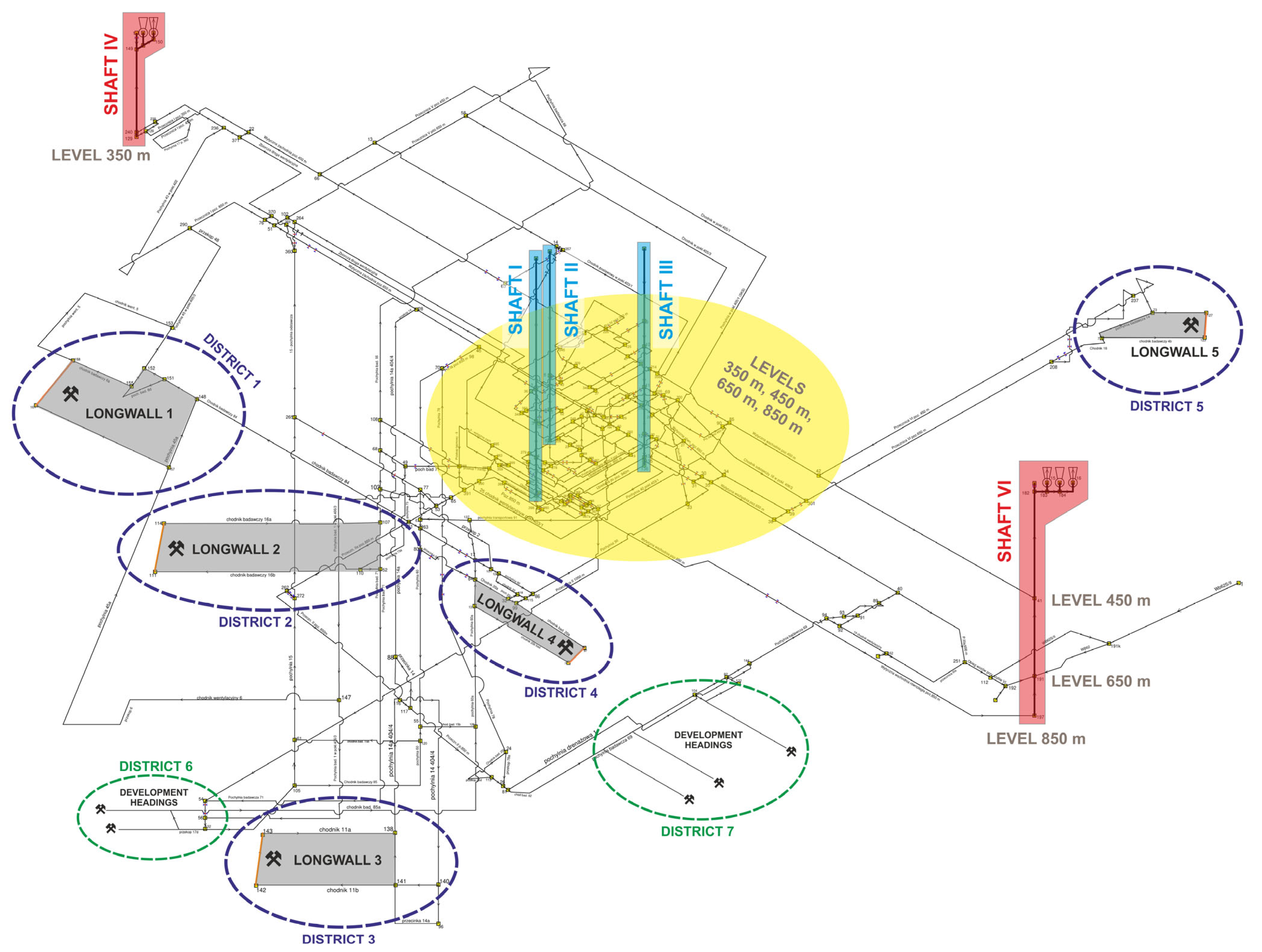
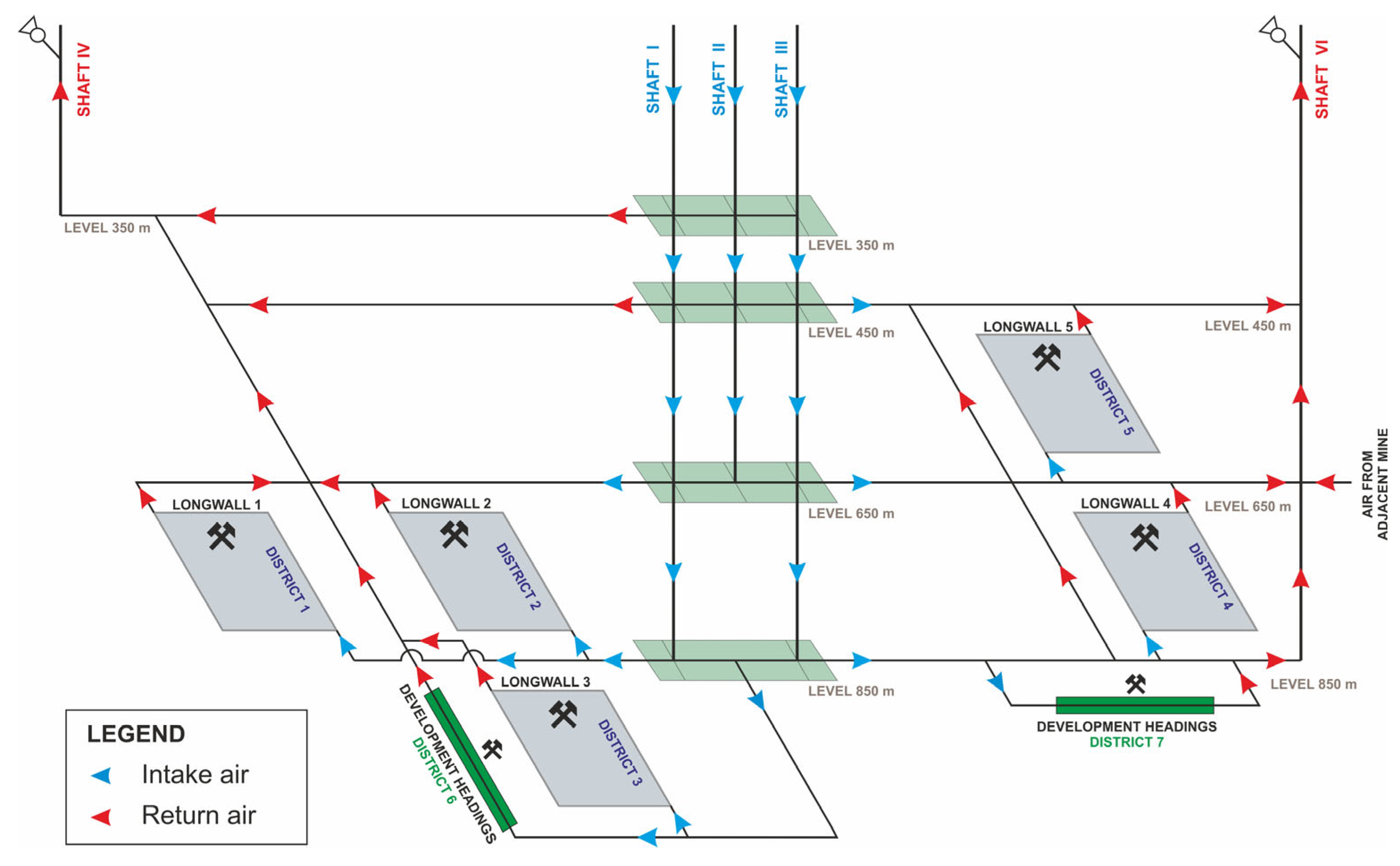
In order to analyze the distribution of air flow, a numerical model of the mine ventilation network was created. The model consisted of 215 nodes and 332 branches. The structure of the ventilation network is presented in Figure 4. The figure shows a full scheme of the current state of the network. Considering the large amount of data and the complexity of the model, a simplified version of the model is presented in Figure 5, showing the general arrangement and the air flow directions from the downcast shafts through the mining districts to the upcast shafts. The calculations presented in the latter part of this article were conducted on the full model of the ventilation network.
In order to update the distribution of the air flow in the model of the ventilation network and to determine the pressure loss, measurements in underground excavations were conducted. The measurements were aimed at identifying the following thermodynamic parameters:
  • Atmospheric pressure at the nodes of the mine ventilation network;
  • Dry bulb temperature and relative humidity of air;
  • Air flow rate in the branches of the ventilation network.
Due to the fact that the parameters of the air are subject to change while measurements are conducted at the bottom of the mine, air pressure and temperature were measured simultaneously on the surface level of the downcast shaft.
Air pressure was measured using precision barometers. The temperature and relative humidity of air were measured with hygrometers, while the air flow rate was measured with vane anemometers. The air velocity was assessed using the traverse method. Along with the air velocity, the cross-section of the excavation was also measured to calculate the air flow in the excavation. Measurements were conducted in a way that enabled the creation of a balance of air flow distribution and compensation for measurement errors.
The analysis of the calculated air flow distribution confirmed the validity of the input data. This is evidenced by the fact that the directions of the air flow in all branches of the network are consistent with those determined by measurements, and the calculated values of air flow approximate the values measured in the ventilation network. Differences between measured and calculated air flows in each branch of the ventilation network do not exceed 5%, which is considered acceptable for this type of calculation. Based on the determined aerodynamic potentials in the network’s nodes, the loss of pressure was calculated for all branches.
The results of air flow calculation carried out for the prepared mine ventilation network were compared with the licensed Ventgraph model used in the mine indicating their consistency. The next part of this article focuses on presenting the air flow in the main parts of the ventilation network, like levels, functional chambers, mining districts, and downcast and upcast shafts. The main purpose of the calculation was to check the possibilities and conditions of changes in the network to ensure appropriate ventilation in mining districts in the future.

4. An Analysis of Airflow Distribution in the Network before Modifications

4.1. Air Flow Distribution

At present, intake air enters the mine through three downcast shafts: Shaft I, Shaft II, and Shaft III. At each level, air is further distributed to the mining districts. Currently, five longwall mining and two independent development heading districts are ongoing.
In the vicinity of downcast shafts, there are functional chambers at the levels of 350 m, 450 m, 650 m, and 850 m. Their functions include pump operation, main switchboard, water drainage, locomotive repair, mechanical and electrical workshops, explosives storage, and locomotive depot.
From the mining districts, the air is returned to the surface via two upcast shafts situated at the peripheries of the network: Shaft IV and Shaft VI.
The total amount of intake air that enters the mine via shafts is 21,100 m3/min; the relative contributions of individual shafts are presented in Table 1. The mine’s ventilation network connects with the adjacent mine, through which approximately 5000 m3/min of air is supplied. This is return air, transferred directly to Shaft VI. In total, 26,100 m3/min of air is supplied to the mine; of this amount, 80% enters the mine via downcast shafts, while the remaining is return air from the adjacent mine.
The largest air flow (11,050 m3/min) enters the mine via shafts to the level of 850 m and constitutes 42% of the total amount of air entering the mine. In terms of the amount of air entering, level 650 m comes second with 8050 m3/min of air, making up almost 31% of the total amount. Smaller air flows reach the levels of 450 m and 350 m: 1600 m3/min and 400 m3/min, respectively, which corresponds to 6.1% and 1.5% of the total amount. Given the present state of the ventilation network, Shaft I supplies 37.9% of all air entering the mine. Shaft III supplies 28.4% of air, while the smallest amount 14.6% is supplied by Shaft II. The remainder of the total air flow is supplied from the ventilation network of the adjacent mine. At each level, part of the air flow is used to ventilate the functional chambers.
Table 2 presents the airflow returned from the mine via ventilation shafts from particular levels. The largest amount of air is removed from the level of 650 m, followed by the level of 350 m. From the level of 650 m, 13,150 m3/min of air is removed, which represents more than 50% of all return air leaving the mine. As for the level of 350 m, the returned amount is 8000 m3/min, i.e., more than 30% of all return air. It must be noted, however, that this distribution results only from the fact that Shaft IV is only 350 m deep, while Shaft VI is not connected to the level of 350 m, but to the level of 450 m. Considering this, it can be assumed that half of all return air in the mine is removed from the level of 650 m and the other half from the levels of 350 m/450 m.
Volumetric flow rates of air supplied to the mining districts are presented in Table 3. Moreover, some districts with longwall development headings are also in progress. If they are located in the district with the longwall, however, they were not included separately in the balance.
The completed balance of intake air indicates that a total amount of 12,950 m3/min supplies the mining districts. Of this amount, 8150 m3/min is distributed to longwalls and 4800 m3/min to places where development headings are constructed and ventilated with an independent air flow. In total, approximately 61% of air supplying the mine via shafts reaches districts with mining activity. About 4000 m3/min of air is used to ventilate functional chambers, which represents approximately 19% of the total amount of air supplied to the mine via shafts. The remaining air is lost in the ventilation network.
The distribution of air flow in the mine is guaranteed by fans installed at Shaft IV and Shaft VI. At Shaft IV, two fans are installed. At present, one of the fans (No. 1) is working, whereas the other (No. 2) is in reserve. At Shaft VI, three fans are installed. At present, two of the fans (No. 1 and No. 2) are working, whereas the third fan (No. 3) is in reserve. Fan parameters are presented in Table 4.
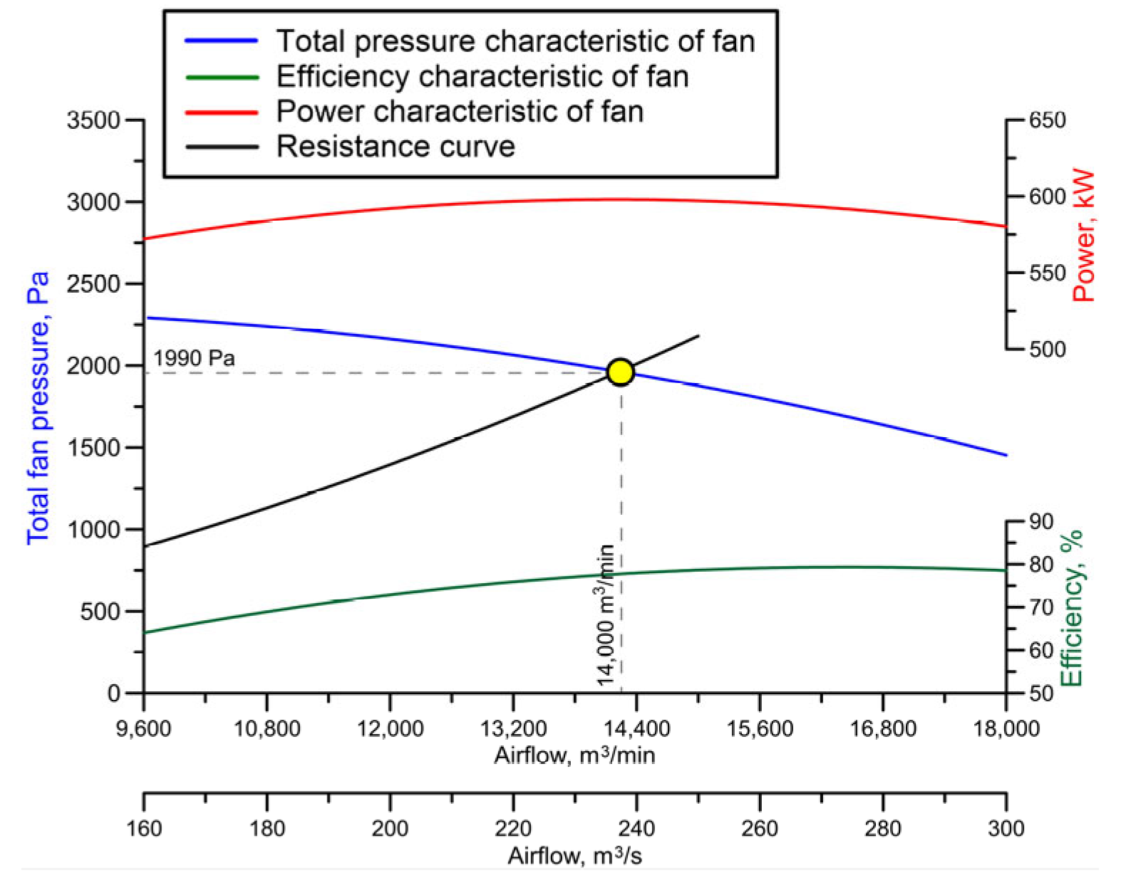
In the current state of the ventilation, the total fan pressure at Shaft IV is 1990 Pa, and its air flow is 14,000 m3/min. External losses of air at Shaft IV amount to 6000 m3/min due to the necessity of supplying air to keep the working fan stable. This solution has many adverse effects and is highly inefficient. Nevertheless, because of the high air drag in the subnetwork, it remains the only viable option.
At Shaft VI two fans are working. Their parameters, especially the total fan pressure, are very similar, and for this reason they are combined in Table 4. The total fan pressure at Shaft VI is approximately 2980 Pa. Their combined air flow is 19,500 m3/min. The external losses of air at Shaft VI are approximately 9% (1850 m3/min).
Figure 6 presents the characteristics of the fan (No. 1) at Shaft IV with its operating point. Figure 7a,b present the characteristics of the fans (No. 1 and No. 2) at Shaft VI with their operating points.
The calculations and the analyses of the fan parameters confirm that the fans installed at Shafts IV and VI work stable and are economically viable.
It must be remembered, however, that the fan at Shaft IV has a very high share of external losses. Due to the very high equivalent drag of the subnetwork, it was decided to unseal the shaft. Had this not been carried out, the fan would have been unstable. Considering the addition of external air, the functioning of this fan must be described as inefficient. This shaft is not likely to contribute to the future mine operation, so it should be closed.

4.2. Conclusions Concerning the Present Situation

Over 60 years of coal exploitation in the analyzed mine has demonstrated the need to exploit lower coal seams. Further development of the mine requires the construction of new excavations. Due to the high development costs, especially the costs of constructing new shafts, the mine operator is planning changes in the ventilation network air flow.
In the mine under discussion, more than 20 million tons of coal is bound in the pillar of Shaft IV. This deposit is already open to mining activity and gaining access to it does not require large investments. Due to this, the mine operators are considering closing Shaft IV to release the deposit bound in its pillar and enable extraction. Closing a ventilation shaft, however, is not possible without securing another way to return air from the underground workings. For this reason, it is speculated that one of the centrally located shafts could be converted from a downcast to an upcast one, a proposal that is discussed at length below. In order to implement such a conversion, it is necessary to carry out an in-depth analysis of its impact on the ventilation network, so that adequate ventilation is guaranteed.

5. An Analysis of the Planned Modifications to the Ventilation Network

5.1. The Scope of the Planned Modifications

To maintain the required intensity of ventilation throughout the mine, the possibility of converting one of the centrally located shafts from a downcast to an upcast one was considered. The only replacement for Shaft IV due to its technical functions and vertical transport in the mine is Shaft III.
An analysis was conducted to assess the possibility of modifying the network in such a way that will ensure sufficient ventilation to continue with the planned extraction. Extraction has been planned in seams 405/1 (three longwalls), 405/3 (four longwalls), 406/3 (five longwalls), 407/3 (five longwalls), 408/2 (six longwalls), 408/3 (six longwalls), and 410 (five longwalls). Most of the planned activity will be conducted between the levels of 850 m and 650 m. An analysis of the planned opening reveals that most of the above seams will have to be supplied with air from the level of 850 m, while the return air will pass to the level of 650 m. Only the deeper seams will be ventilated with air from workings below the level of 850 m.
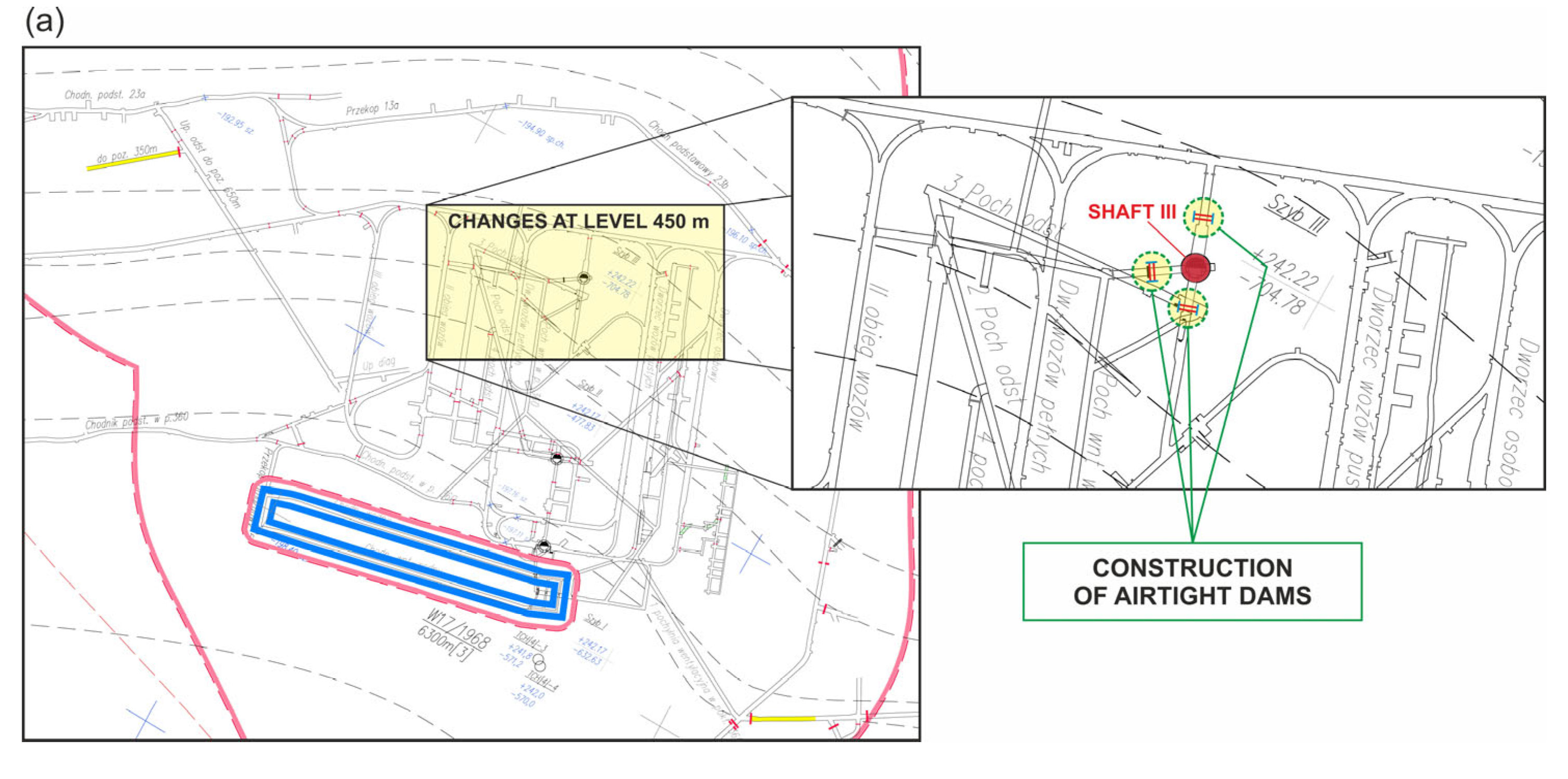
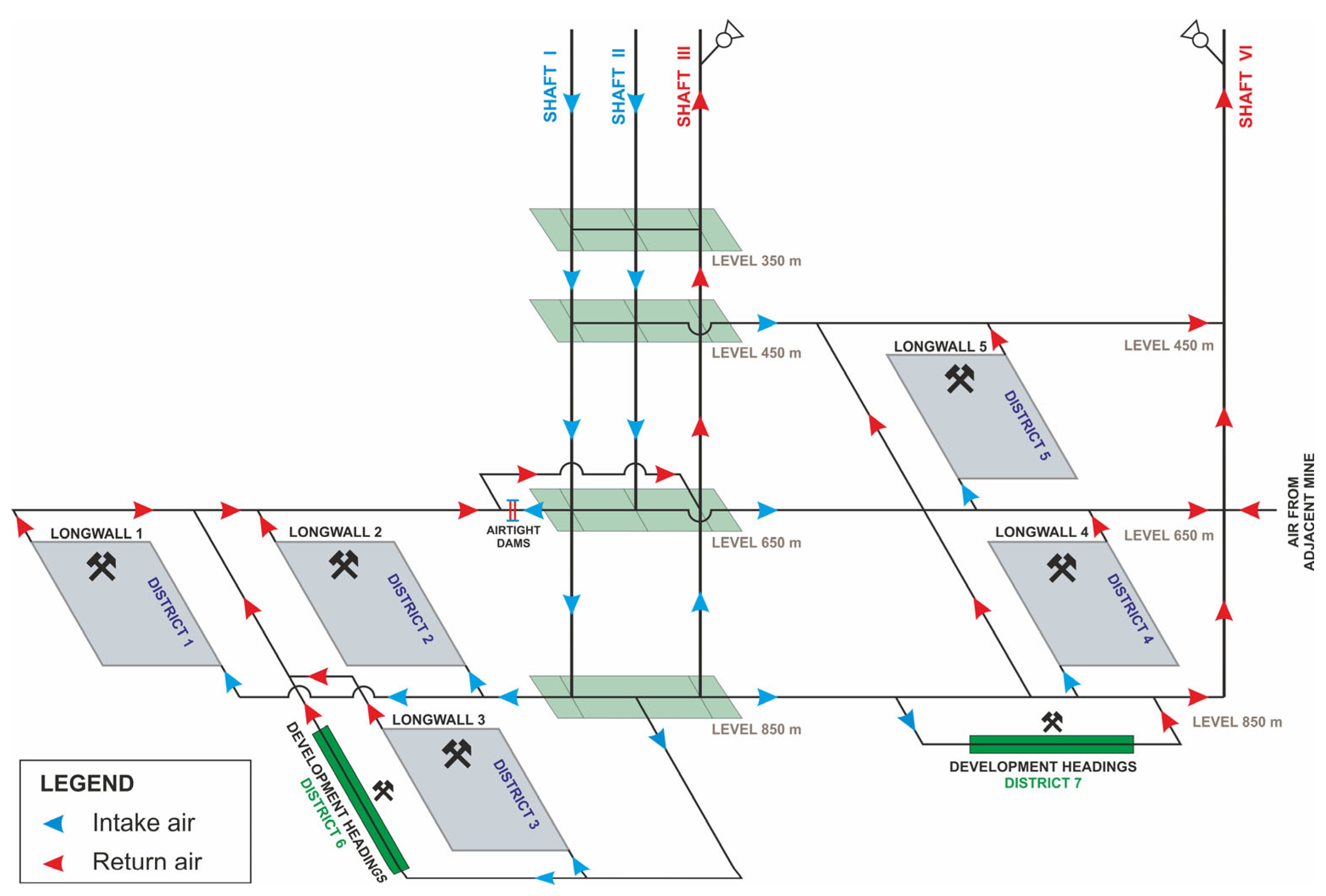
In their largest scope, modifications to the ventilation network will consist of closing Shaft IV combined with converting Shaft III from a downcast to an upcast one. This will require considerable changes to the ventilation network, including the installation of a primary fan station in the vicinity of Shaft III. These modifications will have a great influence on the distribution of air flow in the ventilation network. The most considerable adaptations will be required in the shaft bottom areas of shafts I, II, and III on every level. This need results from the fact that the shafts are arranged as twins and are linked to the workings on all active levels. Substantial changes will occur in the workings situated between the converted Shaft III and the closed Shaft IV. The scope of the necessary changes, consisting of isolating Shaft III with dams from the other excavations at the levels of 450 m, 650 m, and 850 m is presented in Figure 8a–c. At the level of 650 m, separate ventilation routes of return air will have to be assured to transfer the air to the converted Shaft III. A simplified scheme of the ventilation network after closing Shaft IV combined with converting Shaft III from a downcast to an upcast one is presented in Figure 9.
An important aspect of converting Shaft III is the fact that it is considered a possible route for transporting materials and/or coal output to the surface. The twin-like arrangement of Shaft I, Shaft II, and Shaft III means that the shafts will have to be isolated with sealed dams on virtually every level. In many cases, airtight dams will have to be provided, but at the same time will have to allow the material to pass through. To enable delivery of coal output, apertures for conveyor belts will have to be provided. Should the sealing of the dams be ineffective, considerable loss of air will occur.
In the latter part of this article, we will discuss ventilation options available after closing Shaft IV and at the same time converting Shaft III from a downcast to an upcast one. The calculations take into account the various technical functions performed by Shaft III. Also, the existing connection between the ventilation networks of the analyzed mine and the adjacent mine area was included.

5.2. Possible Equipment of the Shaft after Conversion to an Upcast Shaft

During the analysis of the ventilation possibilities after converting Shaft III, the following variants of the technical functioning of the shaft were considered:
  • Solution 1—removing all shaft hoisting (only the ventilation function of Shaft III is retained);
  • Solution 2—converting the shaft hoisting from skip hoisting to cage hoisting for transporting long elements, and the removal of skip hoisting from the second compartment;
  • Solution 3—the removal of skip hoisting from one of the compartments and converting the shaft hoisting in the other compartment to the functions of transporting both the personnel and the output (cages combined with skips);
  • Solution 4—leaving the skips in both compartments of the shaft.

5.3. An Analysis of the Calculated Values

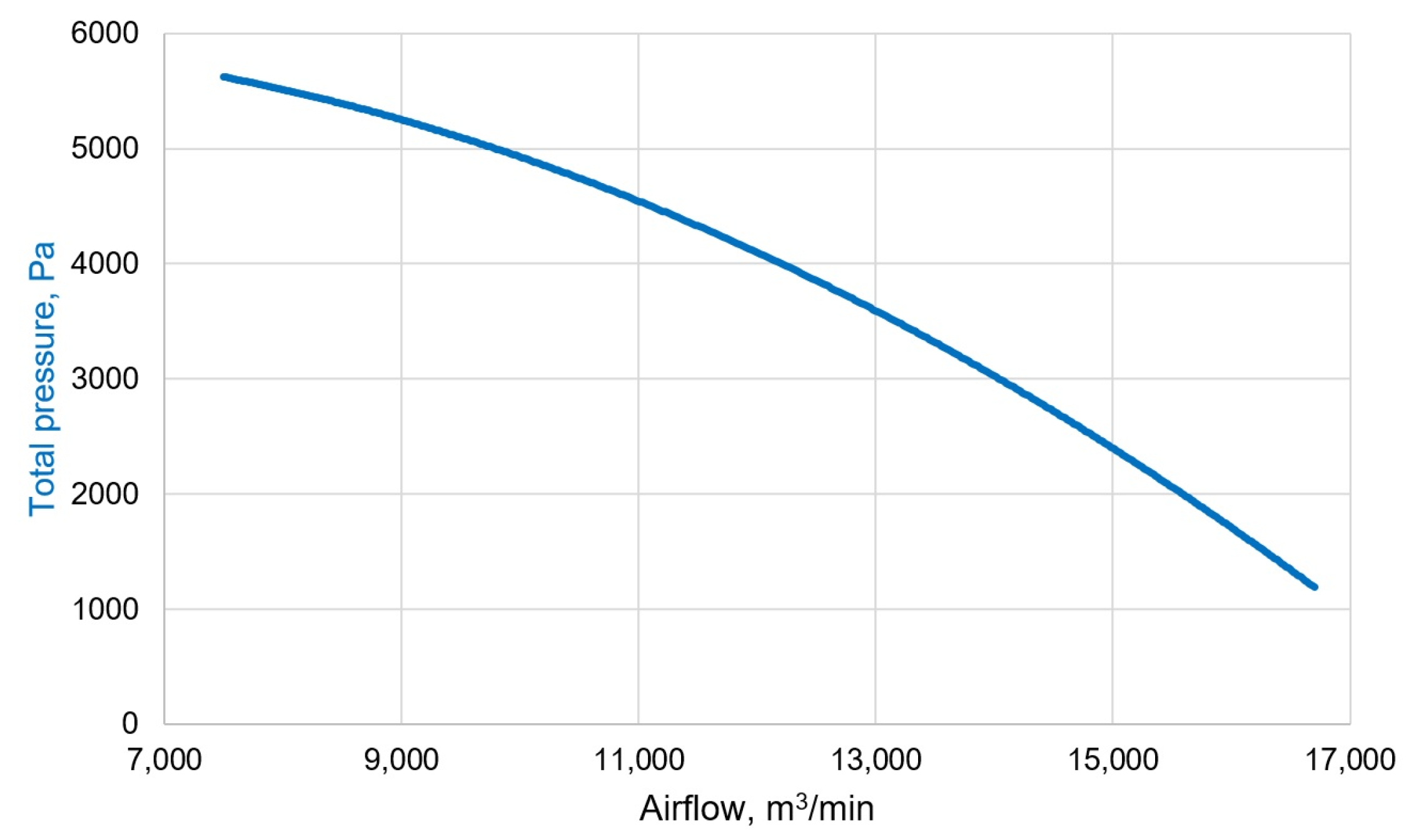
After closing Shaft IV, the ventilation of the excavations in mining districts should retain its present intensity, which is connected primarily with the forecasts of methane hazard for the years to come. It must be borne in mind that coal extraction in the mine is conducted in the presence of serious methane hazards. Considering the demand for air flow in the mining districts and the central localization of Shaft III relative to Shaft I and Shaft II, which will influence the amount of lost air, the return air flow through Shaft III should amount to 10,000 m3/min. To compensate for the external losses, the required performance of the fan is approximately 11,000 m3/min. The parameters of the fan installed in the network are satisfactory. Taking into account the planned depth of extraction in the western part of the plant, including sublevel mining, the pressure drop of the fan should be approximately 3000–3500 Pa. The calculations related to future extraction in the western part of the mine assume mining activity in two areas: one longwall during exploitation and one area with development workings.
Such parameters, plus a small allowance, are offered by, e.g., a fan whose characteristics are presented in Figure 10. In subsequent calculations, it is assumed that this fan will be employed. The selected parameters of the primary fan (efficiency of approx. 11,000 m3/min; pressure drop of approx. 3000–3500 Pa) will sustain the current air flow to underground workings. An important factor for determining the working parameters of the fan was the technical execution of the dams separating the supply and return air flows.
The preliminary calculations have proved that the current structure of the ventilation network will not provide ventilation routes for the return air. The present scope and state of the excavations make it impossible to allocate a duct of return air leading to Shaft III and allow the removal of return air, mainly from the western part, currently ventilated by Shaft IV. The only possible excavation to serve this purpose could be Maingate Road No. 1 in seam 405/3 at level 650 m, but as was already mentioned, its state and cross-section do not offer a sufficient air flow rate.
In order to increase the capacity of return ventilation routes, it will be necessary to perform an additional excavation parallel to Maingate Road No. 1 in seam 405/3 at level 650 m. The new excavation will join the cross-cut level of 650 m and the shaft bottom at the level of 650 m in the area of Shaft III (Figure 11). According to preliminary estimates, the length of the new excavation will be approximately 800 m, and the cross-section area should be 18.0 m2.
Table 5 presents a summary of the analysis of air flow distribution in the ventilation network after closing Shaft IV and converting Shaft III from a downcast to an upcast one, taking into account the modifications to the equipment installed in Shaft III (solutions 1–4). The table shows evidence for the decrease in air flow in the mining areas compared with the current state and the air flow rates in Shaft III, assuming the new fan will be in operation.
The calculations prove that after performing an additional excavation and providing only the ventilation function (solution 1—no equipment installed) or only the transport function of Shaft III (solution 2), the intensity of ventilation mining districts will be not much smaller than at present. As for the longwall mining districts, the supplied air flow will decrease by about 6÷7%; taking into account the development headings district, the decrease will reach about 12÷13%.
In the case of Shaft III, which is equipped with the coal output delivery function (solutions 3 and 4), the intensity of ventilation in the mining districts will decrease by almost 20%, which must be considered insufficient given the depth of extraction and the scale of methane hazard. Also, losses of air supplied to Shaft III will rise considerably to approximately 48%, which is unfavorable. For this reason, such a structure of ventilation in this mine is unacceptable.
The conducted analyses prove that converting Shaft III from a downcast to an upcast one after closing Shaft IV is a feasible option. The measures assessed here have an enormous advantage: they will release a big part of the deposit (more than 20 million tons) that is currently bound in the pillar of the shaft intended for closure. The deposit is already open and available for mining activity. However, despite performing additional excavations, this measure will cause difficulties with maintaining the current intensity of ventilation in development heading districts (for the analyzed solutions the decrease will reach about 22÷24%). Although it is possible to install a fan in Shaft III that will provide higher intake air flow in the mine ventilation network than in the current state (depending on the analyzed solution it could be about 9÷13% higher intake air flow), the losses of air in the network will aggravate. To a large extent, these losses will be inevitable due to the twin-like arrangement of Shaft III and the downcast Shafts I and II. These shafts will be connected at several levels.
In addition, we must remember the necessity to construct a variety of sealed stoppings to isolate the excavations at the shaft bottoms at particular levels, which may be a challenging task. The dams must be airtight. Also, it must be taken into account that Shaft III is intended to function as a transport route for materials or coal output. On these routes, at the crossings of air supply and return, losses of air are bound to occur. In the case of coal output delivery, however, the losses will be significantly greater than in the case of transport, which will be intermittent. In the case of transport routes, it will be possible to install airtight dams to reduce the amount of escaping air.

6. Results Discussion

This article presents the analysis of changing the function of the central Shaft III from a downcast to an upcast one, accompanied by the closure of the peripheral Shaft IV. The main aim of the changes in the mine ventilation network was to assess the possibility of further safe operation without constructing new shafts. An important aspect of converting Shaft III was the fact that it is considered a possible route for transporting materials and/or coal output to the surface. For this purpose, four different variants (solutions 1÷4) of the technical functioning of Shaft III were analyzed.
In the analyzed mine after closing Shaft IV, the ventilation of the excavations in mining districts should retain its present intensity, which is connected primarily with the forecasts of methane hazard for the years to come. Considering the demand for air flow in the mining districts and the central localization of changed Shaft III relative to Shafts I and II, which will influence the amount of lost air, the return air flow through Shaft III should amount to 10,000 m3/min. To compensate for the external losses, the required performance of the fan is approximately 11,000 m3/min. Taking into account the planned depth of extraction in the western part of the plant, including sublevel mining, the pressure drop of the fan should be approximately 3000–3500 Pa.
The preliminary calculations have proved that the current structure of the ventilation network will not provide ventilation routes for return air after planned modifications. To increase the capacity of return ventilation routes, it will be necessary to perform an additional excavation parallel to Maingate Road No. 1 in seam 405/3 at level 650 m.
A solution presented in this article, consisting of closing Shaft IV and at the same time converting Shaft III from a downcast to an upcast one, has been validated as feasible provided that several conditions are met. As for the mine under analysis, the following conclusions may be drawn:
  • Despite closing Shaft IV, it was possible to achieve a higher intake air flow rate (depending on the analyzed solution it could be about 9÷13% higher intake air flow) by creating additional connections to the converted shaft and selecting an adequate primary fan;
  • Following modifications to the structure of air flow distribution, caused by the necessity to allocate ventilation routes for return air, in the area of Shaft III losses of air from the ventilation network increased (in solution 4, the least favorable solution, they reached almost 48%);
  • Losses of air in the network depend to a large extent on the assumed technical function of Shaft III, which is connected with the airtightness of the dams installed there to separate the flows of the supply and the return air. The most favorable option is to use Shaft III solely for ventilation (without hoisting to transport materials and personnel or to deliver coal output to the surface);
  • Finally, the analysis proved that closing one of the shafts might cause a small reduction in the air flow through districts with mining activity (solution 1). In the case discussed here, the supply air flow to the longwall mining districts decreased by less than 6%; if development mining districts are taken into account, the decrease in air flow is almost 12%. Such drops in the intensity of ventilation are acceptable in the analyzed mine, given the existing and forecasted methane hazard;
  • Closing Shaft IV releases the deposit bound in the pillar of the shaft. The deposit has already been made accessible due to mining works, which is economically advantageous.

7. Conclusions

The example presented in this article proves that after closing Shaft IV combined with the conversion of Shaft III from a downcast to an upcast one it is possible to provide sufficient airflow to the planned exploitation areas. In order to ensure the sufficient capacity of return ventilation routes, however, it is necessary to perform an additional excavation parallel to Maingate Road No. 1 in seam 405/3 at level 650 m. The new excavation should connect the cross-cut level of 650 m to the shaft bottom at the level of 650 m. After the new excavation is performed and assigned only the ventilation function, it is possible to remove return air from the mining areas with an intensity similar to that of the current distribution of air flow. Also, it will be possible to provide the required intake air flow and safe exploitation in the years to come.
The procedure presented in this article can be adopted in other mines. Should analogous modifications be considered in other underground mines, it will be necessary to assess the following aspects:
  • In the decision to convert a downcast shaft into an upcast shaft, the following criteria need to be considered: the current functions of the shaft, the possibility of providing return air ventilation routes to the shaft, and the possibility of installing primary fans in the vicinity of the shaft;
  • The benefits of closing a ventilation shaft may include releasing a deposit located in the shaft area. Decisive factors in selecting the shaft to be closed may be its technical condition or relative insignificance for future extraction;
  • An analysis of hazards present in a given mine, especially methane hazards, should be conducted with respect to the forecasts of the required intensity of ventilation needed during future extraction. In the example analyzed here, despite the possibility of increasing the air flow rate in the ventilation network, the modifications caused a decrease in the amount of air flow supplied to the areas with mining activity.
A very useful tool in the abovementioned investigations might be numerical calculations of the distribution of air flow in the ventilation network. Moreover, to conduct the calculations, it is vital to use a model of the network consistent with the measurements of the distribution of air conducted in the mine under analysis.

Author Contributions

Conceptualization, N.S. and M.K.; methodology, N.S. and M.K.; software, M.K.; validation, N.S.; formal analysis, M.K.; investigation, N.S. and M.K.; resources, N.S.; data curation, N.S.; writing—original draft preparation, M.K.; writing—review and editing, M.K.; visualization, M.K.; supervision, N.S.; project administration, M.K.; funding acquisition, M.K. All authors have read and agreed to the published version of the manuscript.

Funding

Research project partly supported by program „Excellence initiative—research university”/Research project partly supported by the Subsidy for the Maintenance and Development of Research Potential at Faculty of Civil Engineering and Resource Management no. 16.16.100.215.

Data Availability Statement

Data are contained within the article.

Conflicts of Interest

The authors declare no conflict of interest.

Nomenclature

k = 1 ,   2 ,   P number of independent junctions
P number of all independent junctions
i = 1 ,   2 ,   N number of independent ventilation branches
N number of all branches
ε k i character-oriented constant of the junction-branch matrix of the network
α m i character-oriented constant of a mesh-branch matrix of a network
m = 1 ,   2 ,   M number of the fundamental mesh m of the network
M number of all fundamental meshes
W i sum of frictional pressure drop and shock pressure losses in a branch i , Pa
p m i sum of the increase in total pressure across the fan, Pa
h n i natural ventilation pressure gain in branch i , Pa
V ˙ i volumetric flow rate of air in branch i , m3/s
R i equivalent resistance of branch i, (N·s2)/m8
s g n V ˙ i positive or negative value depending on the air flow direction within ith branch to the direction defined for the mesh
m ¯   mesh in which all air flows in branches are replaced by air flow of a basic branch
α i m ¯ character-oriented constant of a transpose of a mesh-branch matrix of the network, for replacing air flows in branches by air flows in basic branches
r iteration step

References

  1. De Souza, E. Optimization of complex mine ventilation systems with computer network modelling. IFAC Proc. 2007, 40, 323–329. [Google Scholar] [CrossRef]
  2. Wei, G. Optimization of Mine Ventilation System Based on Bionics Algorithm. Procedia Eng. 2011, 26, 1614–1619. [Google Scholar] [CrossRef]
  3. Feng, W.; Zhu, F.; Lv, H. The Use of 3D Simulation System in Mine Ventilation Management. Procedia Eng. 2011, 26, 1370–1379. [Google Scholar] [CrossRef]
  4. Shen, Y.; Wang, H. Study and Application on Simulation and Optimization System for the Mine Ventilation Network. Procedia Eng. 2011, 26, 236–242. [Google Scholar] [CrossRef]
  5. Wallace, K.; Prosser, B.; Stinnette, J.D. The practice of mine ventilation engineering. Int. J. Min. Sci. Technol. 2015, 25, 165–169. [Google Scholar] [CrossRef]
  6. Wang, W.; Shao, W.; Wang, S.; Liu, J.; Shao, K.; Cao, Z.; Liu, Y.; Cui, Z. Operation Optimization of Thermal Management System of Deep Metal Mine Based on Heat Current Method and Prediction Model. Energies 2023, 16, 6626. [Google Scholar] [CrossRef]
  7. Zhong, D.; Wang, L.; Wang, J.; Jia, M. An Efficient Mine Ventilation Solution Method Based on Minimum Independent Closed Loops. Energies 2020, 13, 5862. [Google Scholar] [CrossRef]
  8. Szlązak, N.; Korzec, M. The Solution of the Main Fan Station for Underground Mines Being Decommissioned in Terms of Reducing Energy Consumption by Ventilation. Energies 2022, 15, 4612. [Google Scholar] [CrossRef]
  9. Liu, H.; Mao, S.; Li, M. A Case Study of an Optimized Intermittent Ventilation Strategy Based on CFD Modeling and the Concept of FCT. Energies 2019, 12, 721. [Google Scholar] [CrossRef]
  10. Pach, G.; Różański, Z.; Wrona, P.; Niewiadomski, A.; Zapletal, P.; Zubíček, V. Reversal Ventilation as a Method of Fire Hazard Mitigation in the Mines. Energies 2020, 13, 1755. [Google Scholar] [CrossRef]
  11. Tutak, M.; Brodny, J.; Szurgacz, D.; Sobik, L.; Zhironkin, S. The Impact of the Ventilation System on the Methane Release Hazard and Spontaneous Combustion of Coal in the Area of Exploitation—A Case Study. Energies 2020, 13, 4891. [Google Scholar] [CrossRef]
  12. Szlązak, N.; Swolkień, J.; Kamiński, P. Design of Coal Seam Exploitation in Methane Hazard Conditions: A Case Study. Energies 2023, 16, 365. [Google Scholar] [CrossRef]
  13. Regulation of the Minister of the Environment on Natural Hazards in Mining. 2021. Available online: https://isap.sejm.gov.pl/isap.nsf/download.xsp/WDU20210001617/O/D20211617.pdf (accessed on 8 February 2024).
  14. McPherson, M.J. Subsurface Ventilation and Environmental Engineering; Chapman & Hall: London, UK, 1993. [Google Scholar]
  15. Pawiński, J.; Roszkowski, J.; Strzemiński, J. Przewietrzanie Kopalń; Ślaskie Wydawnictwo Techniczne: Katowice, Poland, 1995. [Google Scholar]
  16. Scott, D.R.; Hinsley, F.B. Ventilation Network Theory, Parts 1 to 4. Colliery Eng. 1951, 28, 67–71, 159–166, 229–235, 497–500. [Google Scholar]
  17. El-Nagdy, K.A. Stability of multiple fans in mine ventilation networks. Int. J. Min. Technol. 2013, 23, 569–571. [Google Scholar] [CrossRef]
  18. Luo, W.; Xie, X.; Xiao, H.; Cui, C.; Yin, X.; Su, M.; Wang, T.; Li, J.; Tan, X. Reliability calculation of mine ventilation network. Procedia Eng. 2014, 84, 752–757. [Google Scholar]
  19. Maleki, B.; Mozaffari, E. A comparative study of the iterative numerical methods used in mine ventilation networks. Int. J. Adv. Comput. Sci. Appl. 2016, 7, 356–362. [Google Scholar] [CrossRef]
  20. Atkinson, J.J. On the Theory of the Ventilation of Mines. Trans. North Engl. Inst. Min. Engrs. 1854, 3, 118. [Google Scholar]
  21. Wang, Y.J. A Non-linear Programming Formulation for Mine Ventilation Networks with Natural Splitting. Int. J. Rock Mech. Min. Sci. Geomech. 1984, 21, 43–45. [Google Scholar] [CrossRef]
  22. Cross, H. Analysis of flow in networks of conduits or conductors. Univ. Illinois Bull. 1936, 286, 1–32. [Google Scholar]
  23. Acuna, E.I.; Lowndes, I.S. A Review of Primary Mine Ventilation System Optimization. Interfaces 2014, 44, 163–175. [Google Scholar] [CrossRef]
  24. Widzyk-Capehart, E.; Watson, B. Agnew Gold Mine Expansion, Mine Ventilation Expansion Evaluation Using Ventsim. In Proceedings of the 7th International Mine Ventilation Congress, Krakow, Poland, 17–22 June 2001; Available online: https://www.ventsim.com/wp-content/uploads/2019/04/Agnew_Gold_Mine_Expansion_using_Ventsim.pdf (accessed on 8 February 2024).
  25. Marx, W.; Belle, B.K. Simulating Air Flow Conditions in a South African Coal Mine, Using the VUMA-Network Simulation Software. 2002. Available online: https://www.vuma3d.com/wp-content/uploads/2021/04/Simulating-Airflow-conditions-in-a-South-African-coal-mine-using-the-VUMA-network-simulation-software.pdf (accessed on 8 February 2024).
  26. Hardcastle, S.G. 3D-canvent: An interactive mine ventilation simulator. In Proceedings of the 7th U.S. Mine Ventilation Sympos. (Society for Mining, Metallurgy & Exploration), Englewood, CO, USA, 5–7 June 1995; pp. 467–472. [Google Scholar]
  27. Wallace, K.G., Jr. General Operational Characteristics and Industry Practices of Mine Ventilation Systems. 2001. Available online: https://mineventilationservices.com/files/Publications/07th_INT-1.pdf (accessed on 8 February 2024).
  28. Dziurzyński, W.; Kruczkowski, J. Validation of the mathematical model used in the VENTGRAPH programme on the example of the introduction of new headings to the ventilation network of mine. Arch. Min. Sci. 2007, 52, 155–169. [Google Scholar]
  29. von Glehn, F.H.; Marx, W.M.; Bluhm, S.J. Verification and calibration of ventilation network models. In Proceedings of the 12th U.S. North American Mine Ventilation Symposium, Reno, Nevada, 9–12 June 2008; pp. 275–279. [Google Scholar]
  30. Bluhm, S.; Moreby, R.; Von Glehn, F.; Pascoe, C. Life-of-mine ventilation and refrigeration planning for Resolution Copper Mine. J. South. Afr. Inst. Min. Metall. 2014, 114, 497–503. [Google Scholar]
  31. Șuvar, M.C.; Lupu, C.; Arad, V.; Cioclea, D.; Păsculescu, V.M.; Mija, N. Computerized simulation of mine ventilation networks for sustainable decision making process. Environ. Eng. Manag. J. 2014, 13, 1445–1451. [Google Scholar] [CrossRef]
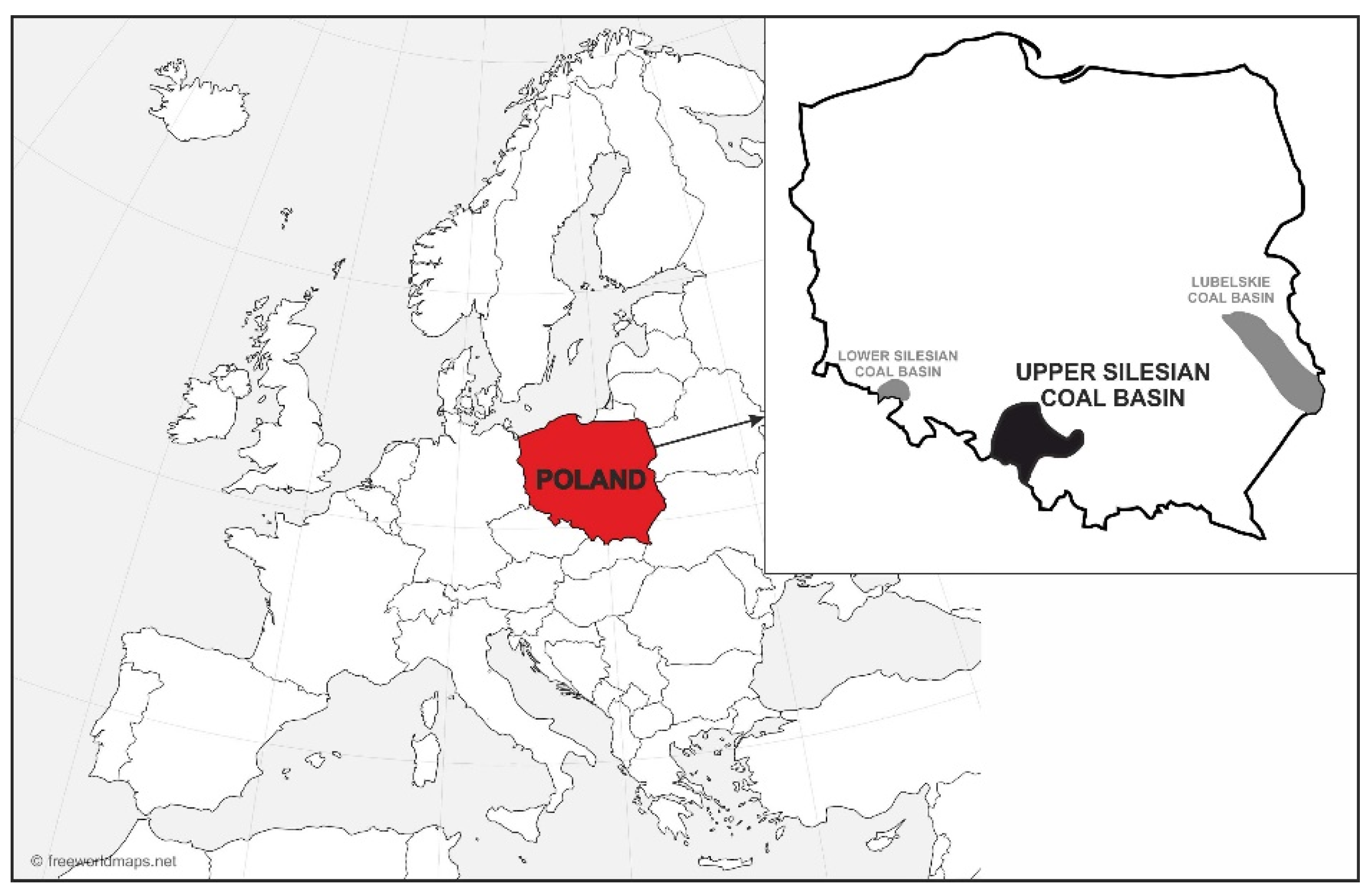
Figure 1. Location of the USCB in Poland and in Europe.
Energies 17 01379 g001
Figure 2. Mine area and the positioning of the shafts.
Energies 17 01379 g002
Figure 3. Total methane emission and amount of captured methane in 2013–2022.
Energies 17 01379 g003
Figure 4. Scheme of the current state of the ventilation network.
Energies 17 01379 g004
Figure 5. Simplified scheme of the ventilation network.
Energies 17 01379 g005
Figure 6. Characteristics of fan at Shaft IV: No. 1 with operating points.
Energies 17 01379 g006
Figure 7. Characteristics of fans at Shaft VI: No. 1 (a) and No. 2 (b) with their operating points.
Energies 17 01379 g007
Figure 8. Dam location at the levels of 450 m (a), 650 m (b), and 850 m (c).
Energies 17 01379 g008aEnergies 17 01379 g008b
Figure 9. Simplified scheme of the ventilation network after closing Shaft IV combined with converting Shaft III from a downcast to an upcast one.
Energies 17 01379 g009
Figure 10. Characteristics of the new main fan to Shaft III.
Energies 17 01379 g010
Figure 11. The new excavation at the level of 650 m in Shaft III.
Energies 17 01379 g011
Table 1. Distribution of intake air in the ventilation network of the mine.
LevelVolumetric Flow Rate, m3/minFlow Rate on
the Level, m3/min
Percentage
of Total
Flow Rate, %
Shaft IShaft IIShaft III
350 m30050504001.5
450 m60080020016006.1
650 m255029502550805030.8
850 m6450-460011,05042.3
Total990038007400--
Intake air entering the mine through shafts21,10080.8
Intake air from the adjacent mine500019.2
Total26,100100.0
Table 2. Distribution of return air in the ventilation network of the mine.
LevelVolumetric Flow Rate, m3/minFlow Rate on
the Level,
m3/min
Percentage
of Total
Flow Rate, %
Shaft IVShaft VI
350 m8000-800030.7
450 m-4450445017.0
650 m-13,15013,15050.4
850 m-5005001.9
Total800018,10026,100100
Table 3. Intake air distribution for longwall mining and development heading districts.
Mining DistrictVolumetric Flow Rate, m3/min
To the Mining
District
To the
Longwall Face
District 1—Longwall 1 in seam 405/31100650
District 2—Longwall 2 in seam 407/31350950
District 3—Longwall 3 in seam 404/415501200
District 4—Longwall 4 in seam 405/126501200
District 5—Longwall 5 in seam 408/31500900
Total (longwall mining districts)81504900
Development headings—districts 6 and 74800-
Total (longwall mining
and development heading districts)
12,950-
Table 4. Parameters of the main fans.
ShaftNumber
of Working Fans
Volumetric Air Flow, m3/minTotal
Pressure, Pa
Equivalent Orifice, m2
In the ShaftExternal LossesFan
Air Flow
ShaftFan
IV18000600014,00019903.816.23
V218,100185019,95029807.007.26
Total26,100785033,950
Table 5. Summary of the analysis of air flow distribution in the ventilation network after closing Shaft IV and converting Shaft III from a downcast to an upcast one.
DescriptionUnitCurrent StateSolution 1Solution 2Solution 3Solution 4
Without New ExcavationAfter Performing an Additional Excavation to Shaft III
Total intake air supplied to the
mine through the shafts
m3/min21,10019,14023,44023,10024,03023,750
Total intake air supplied to the mine26,10024,39028,89028,54029,50029,200
Increase in total intake air supplied to the mine according to the current statem3/min-−17102790244034003100
%-−6.5510.699.3513.0311.88
Intake air supplied
to the mining districts
m3/min12,950945011,41011,25010,42010,420
Longwall mining districts815056307680760067806750
Development headings district480038203730365036403670
Decrease in mining districts ventilation intensity%-−27.0−11.9−13.1−19.5−19.5
Longwall mining districts-−30.9−5.8−6.7−16.8−17.2
Development headings district-−20.4−22.3−24.0−24.2−23.5
Returned air removed from the mine by Shaft IIIm3/min-663011,92011,51012,56012,210
Disclaimer/Publisher’s Note: The statements, opinions and data contained in all publications are solely those of the individual author(s) and contributor(s) and not of MDPI and/or the editor(s). MDPI and/or the editor(s) disclaim responsibility for any injury to people or property resulting from any ideas, methods, instructions or products referred to in the content.