Design and Implementation of a Linear Induction Launcher with a New Excitation System Utilizing Multi-Stage Inverters
Abstract
1. Introduction
- (i)
- The impracticality of adjusting frequency and current by altering the values of circuit elements or changing the speed of the generator;
- (ii)
- The low efficiency resulting from energizing regions on the barrel where no projectile is present.
- (i)
- To present a modular and highly efficient launcher system, analyze and simulate inverter power circuits, and develop an FPGA-based central control unit hardware and VVVF algorithms to control the inverters;
- (ii)
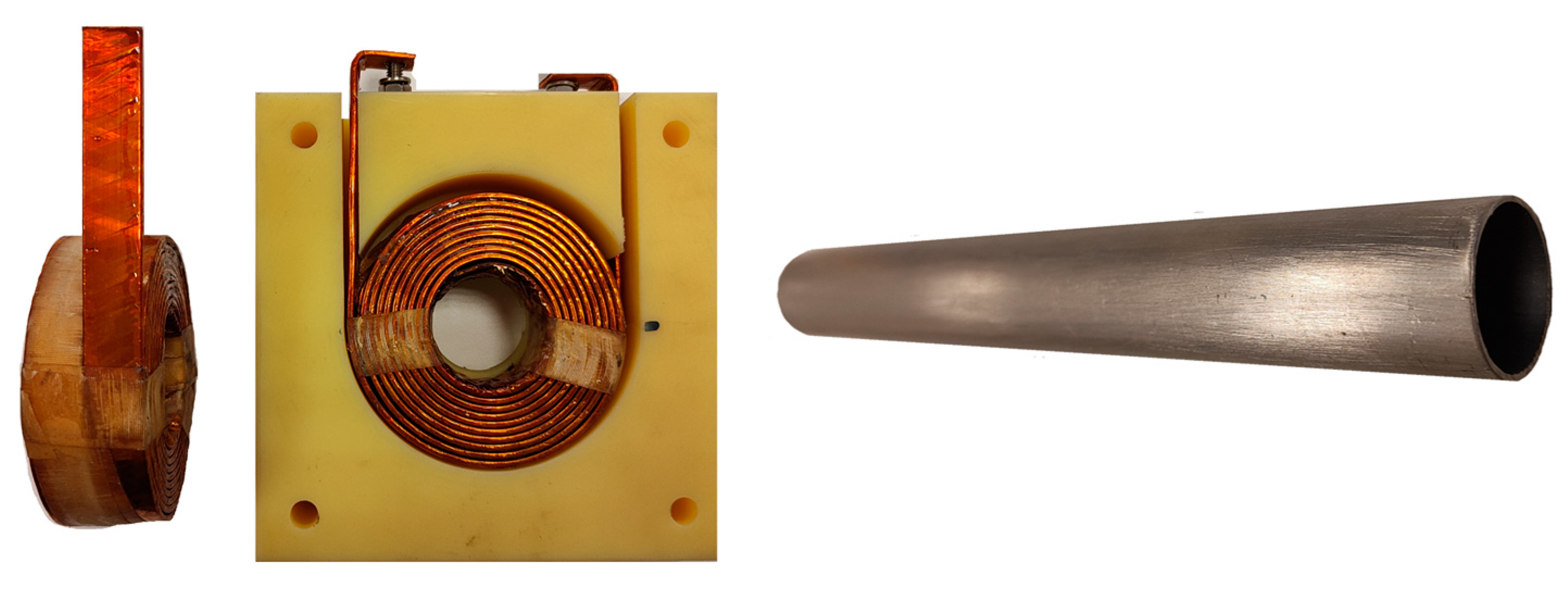
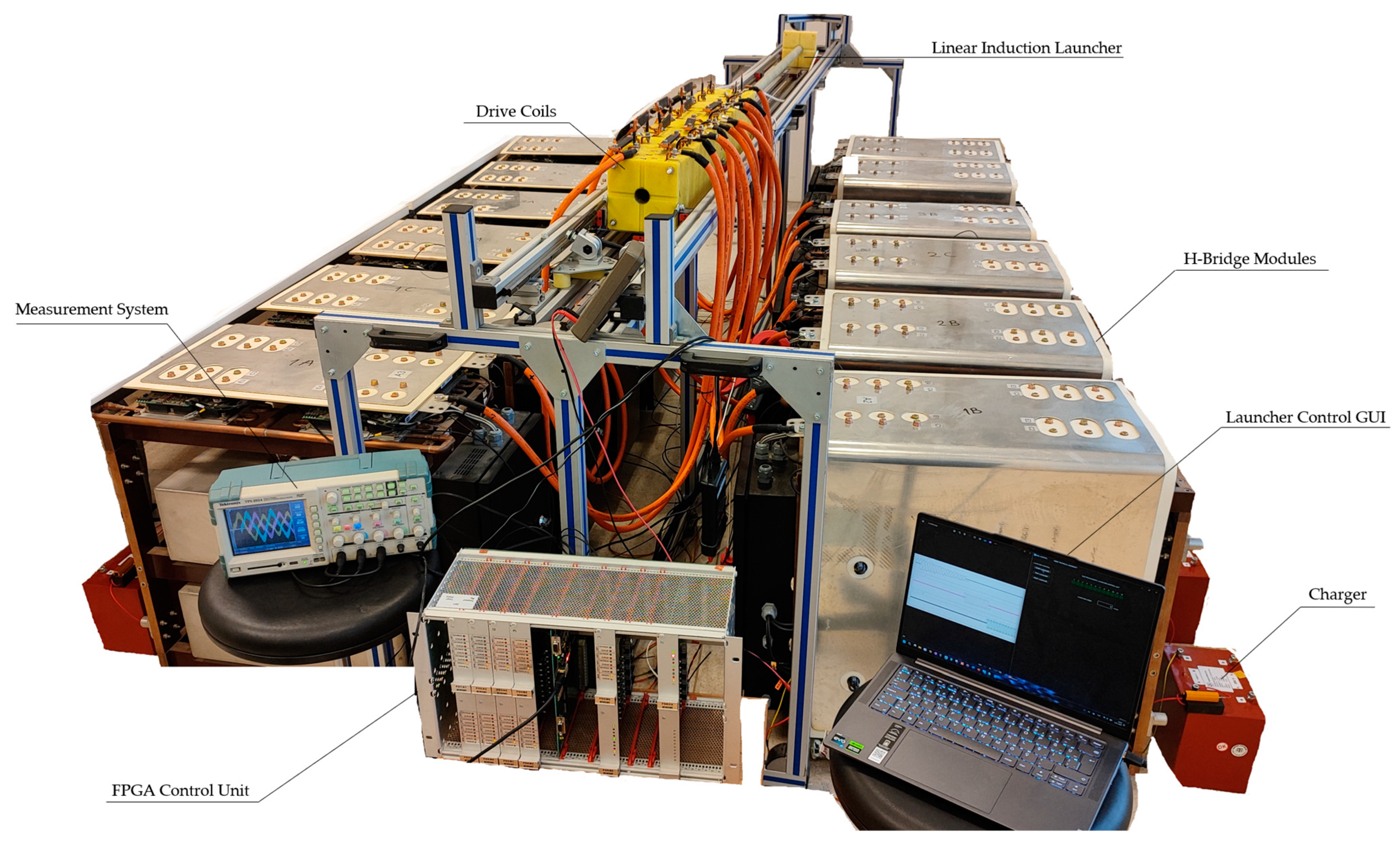
- To implement a laboratory-scale linear induction launcher prototype, including high-power IGBT H-bridge modules, FPGA-controlled fiber-optic transceivers, a high-voltage capacitor charger circuit, and a laser position detection system;
- (iii)
- To optimize the continuity of the traveling magnetic wave in order to minimize thrust fluctuation using 3-D FEM analysis;
- (iv)
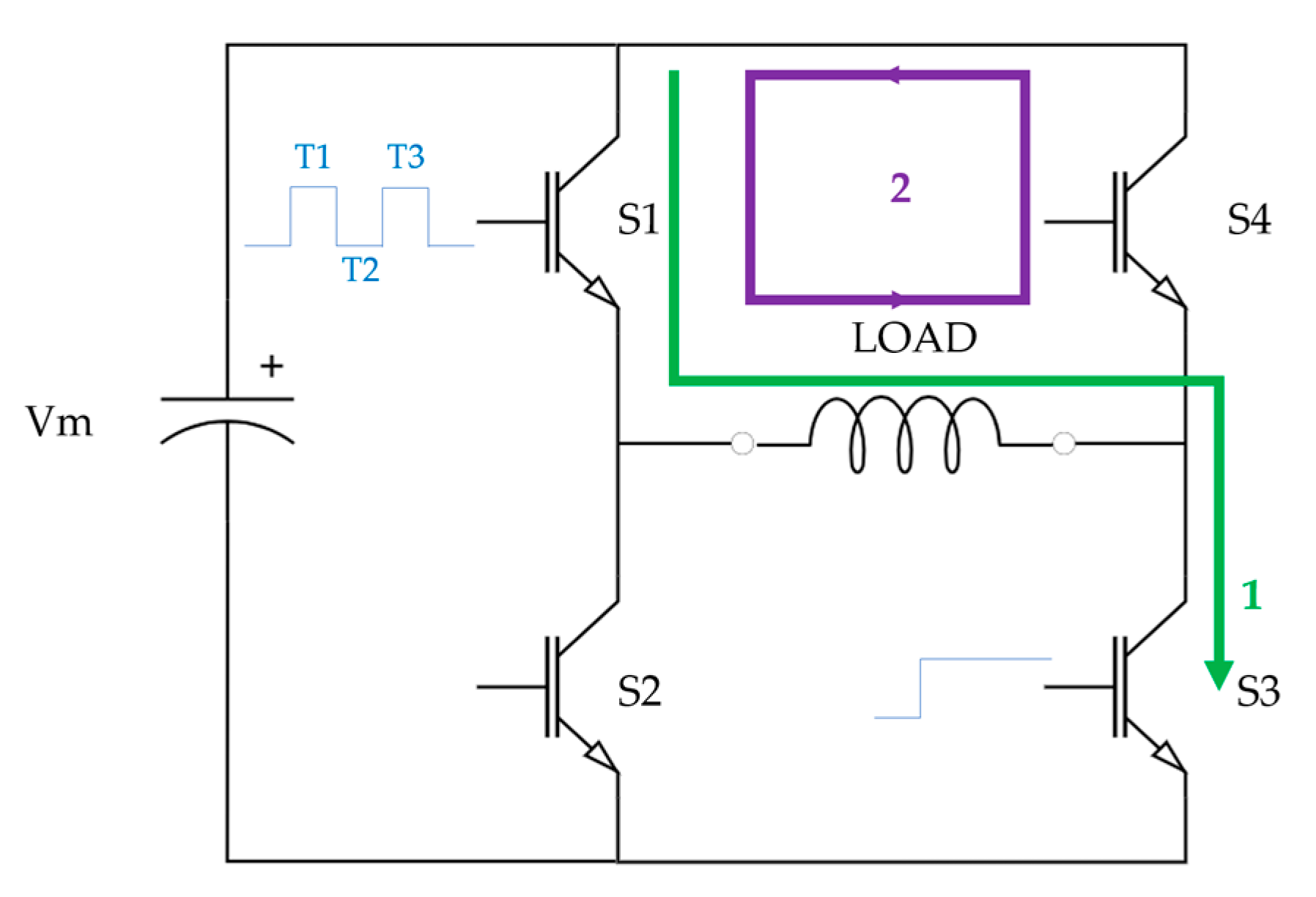
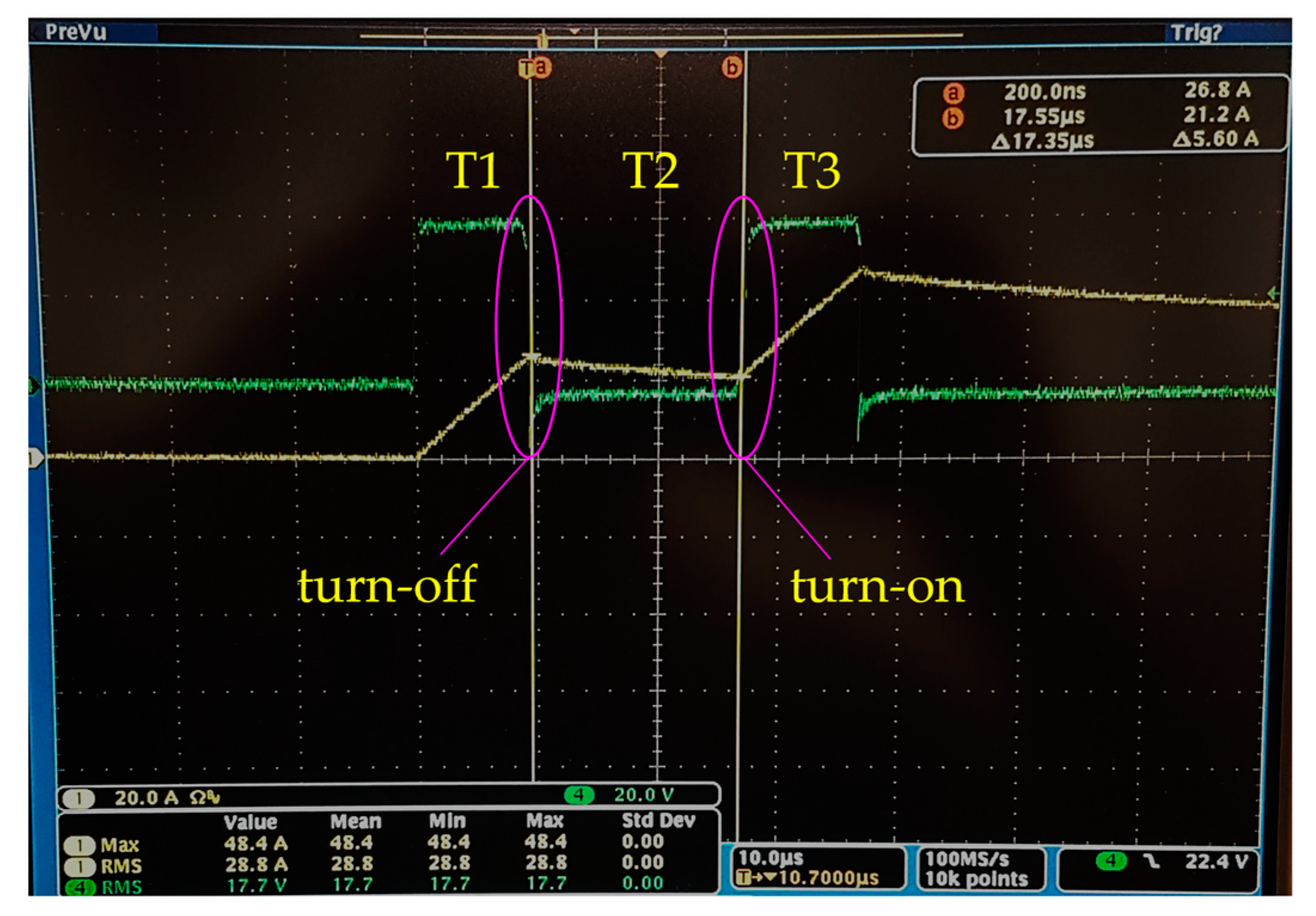
- To verify the proper operation of IGBT switches and drivers for each H-bridge module using the double pulse testing method;
- (v)
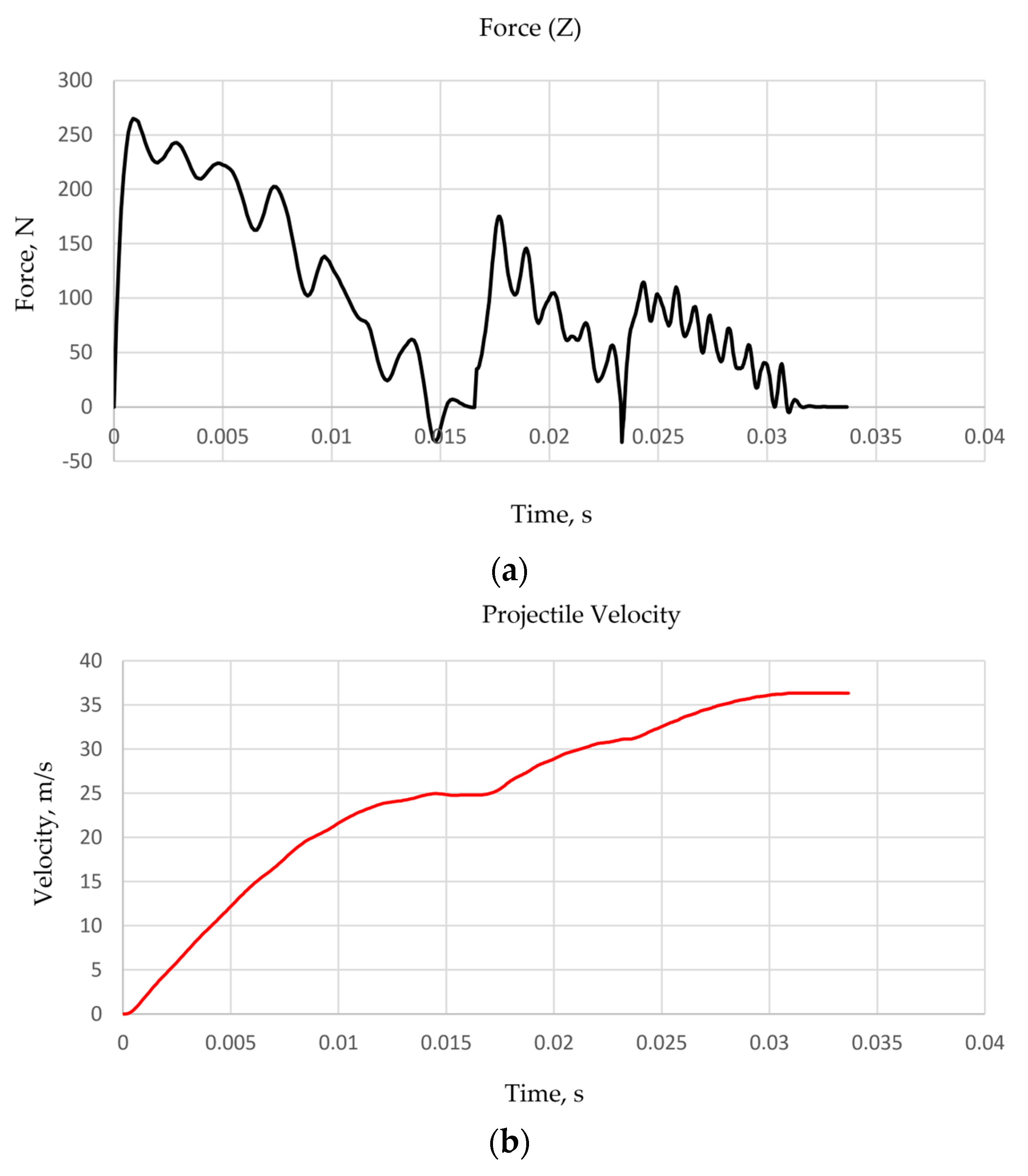
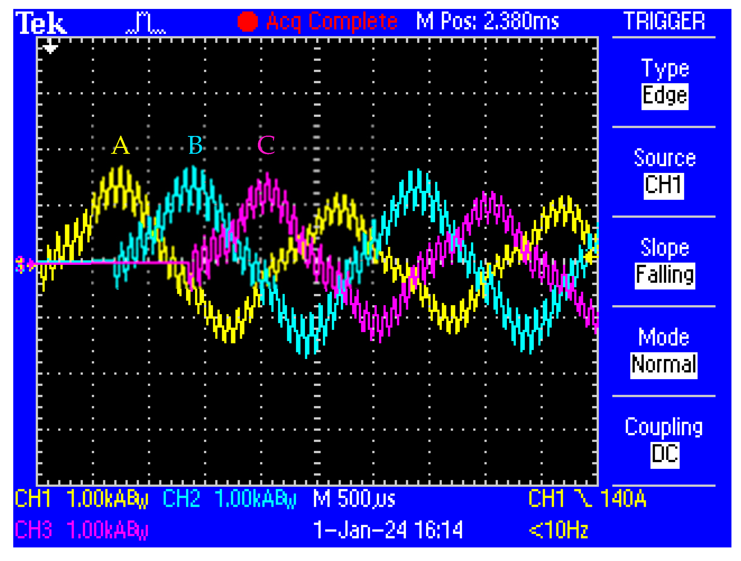
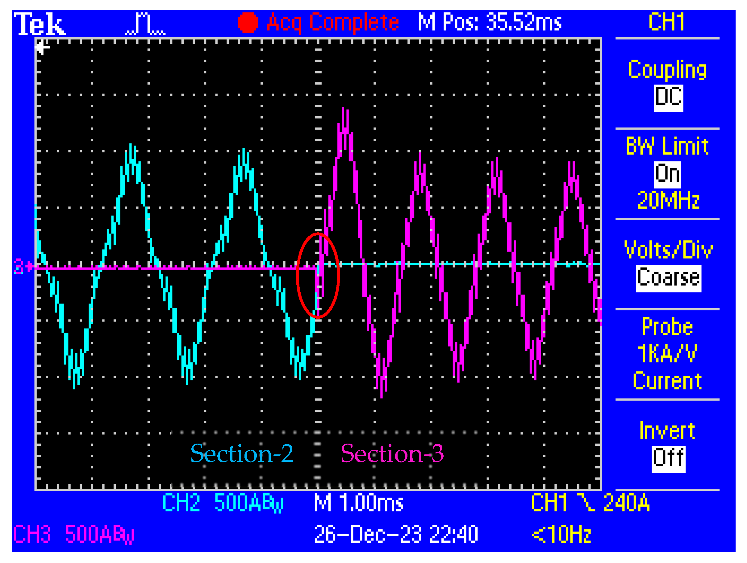
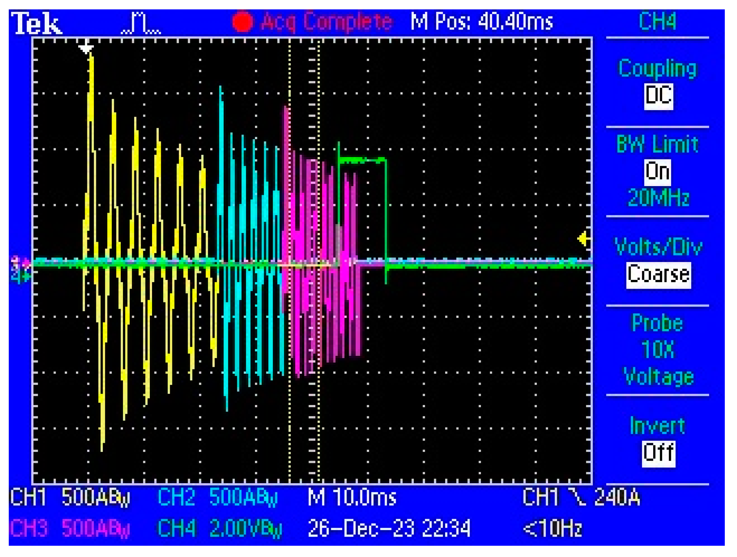
- To demonstrate the projectile’s acceleration to the intended velocity with high efficiency using current, voltage, and speed measurement results.
2. System Design
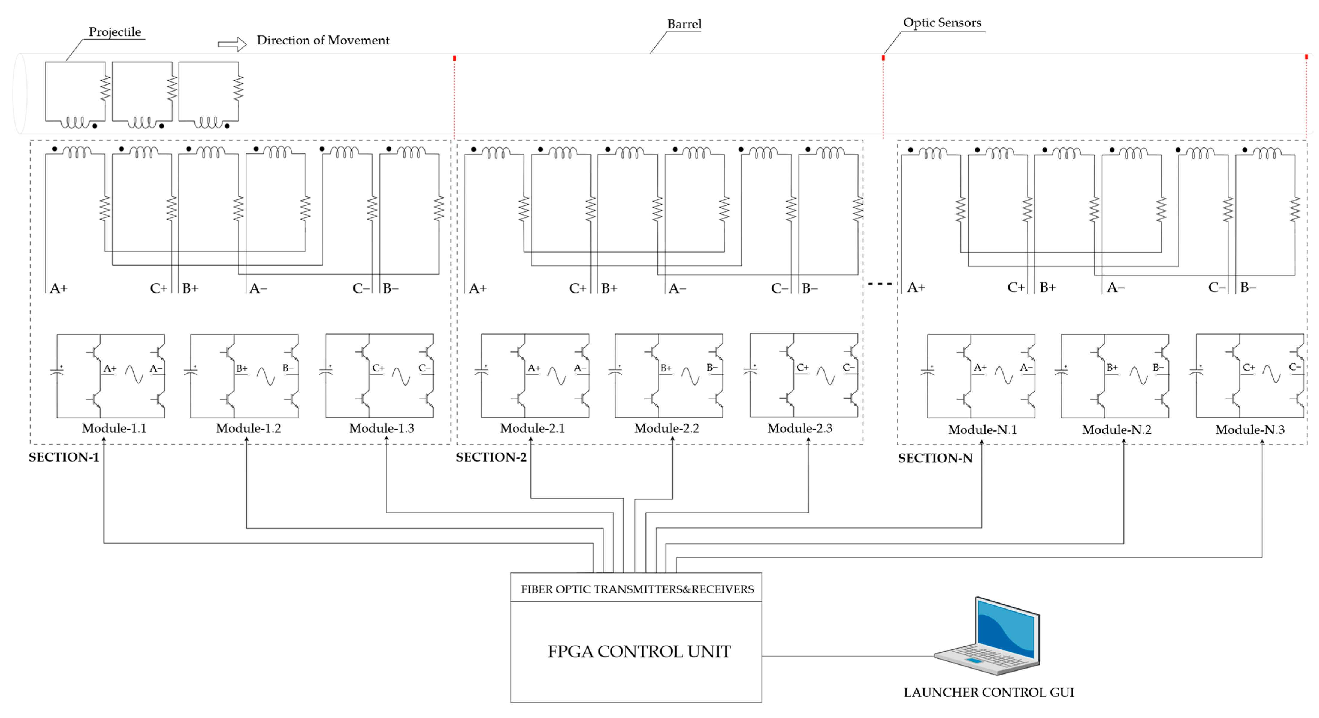
- Launcher: including barrel, coil, projectile, and optical speed sensors;
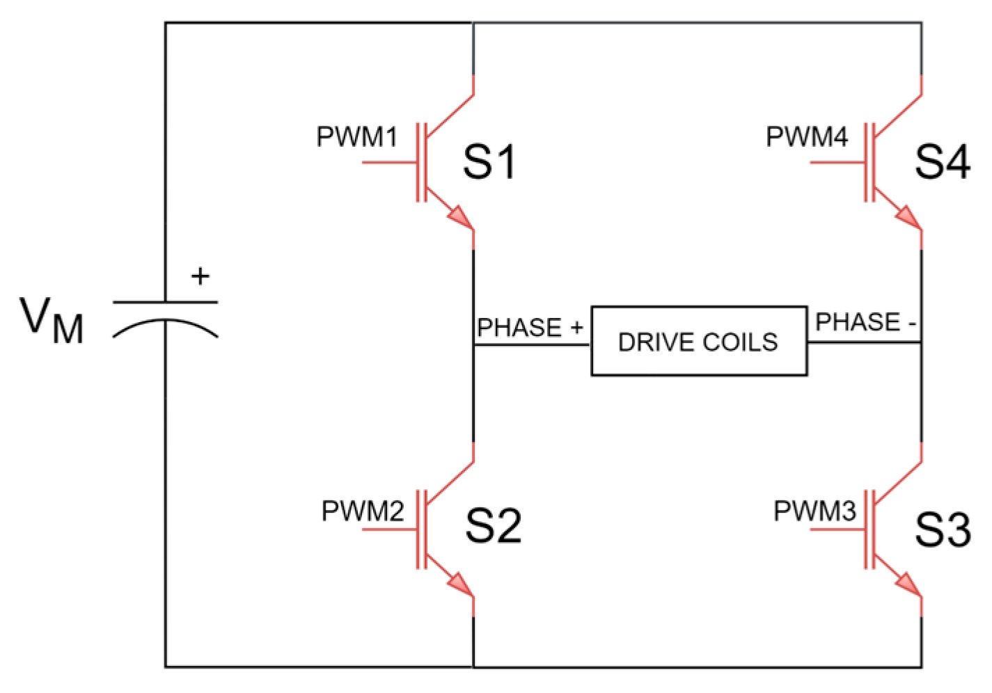
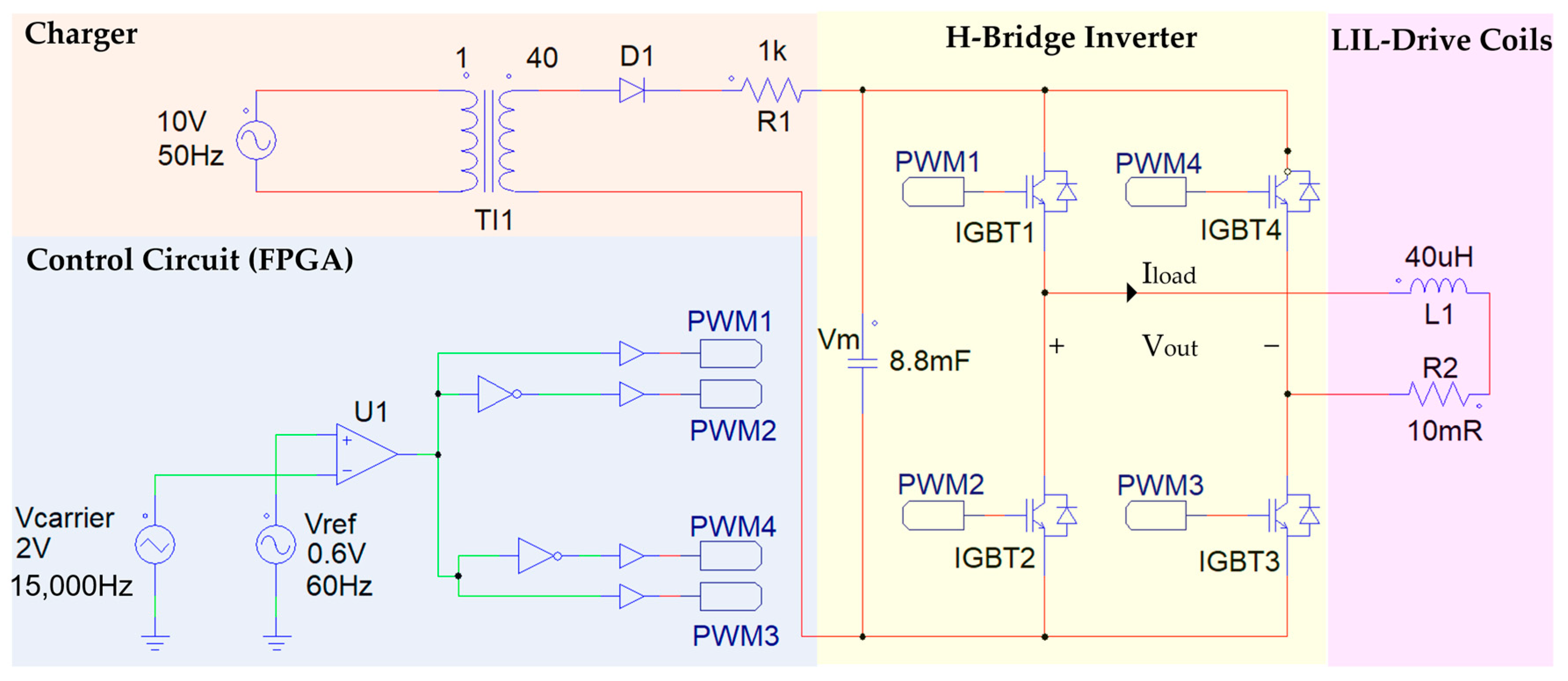
- Power stage: including IGBT power switches and their drivers, high-voltage capacitors, and chargers;
- FPGA Control Unit: implementation of a launcher algorithm, generation of fiber-optic PWM signals for H-bridge inverters, projectile position control, and GUI communication.
- The axial length of a barrel coil;
- Non-dimensional functions that depend only on the pole pitch and the dimensions of the launcher;
- Voltage, current, and turns per coil.
3. Power Stage
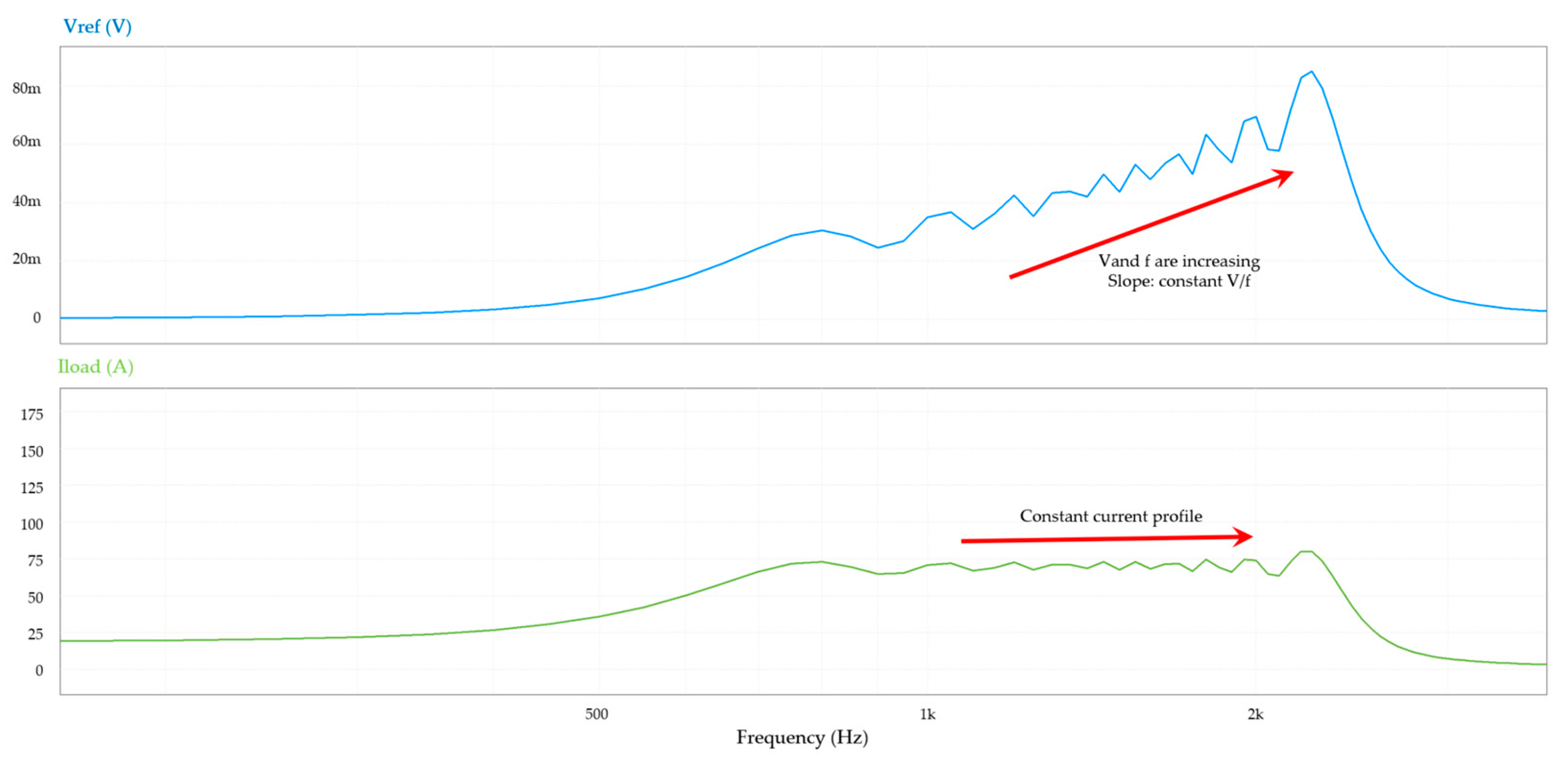
3.1. Scalar V/f Control
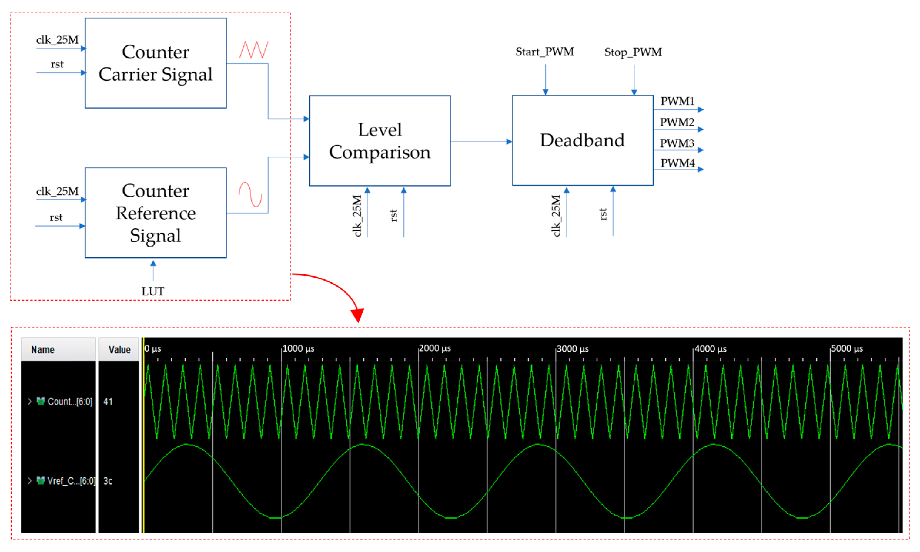
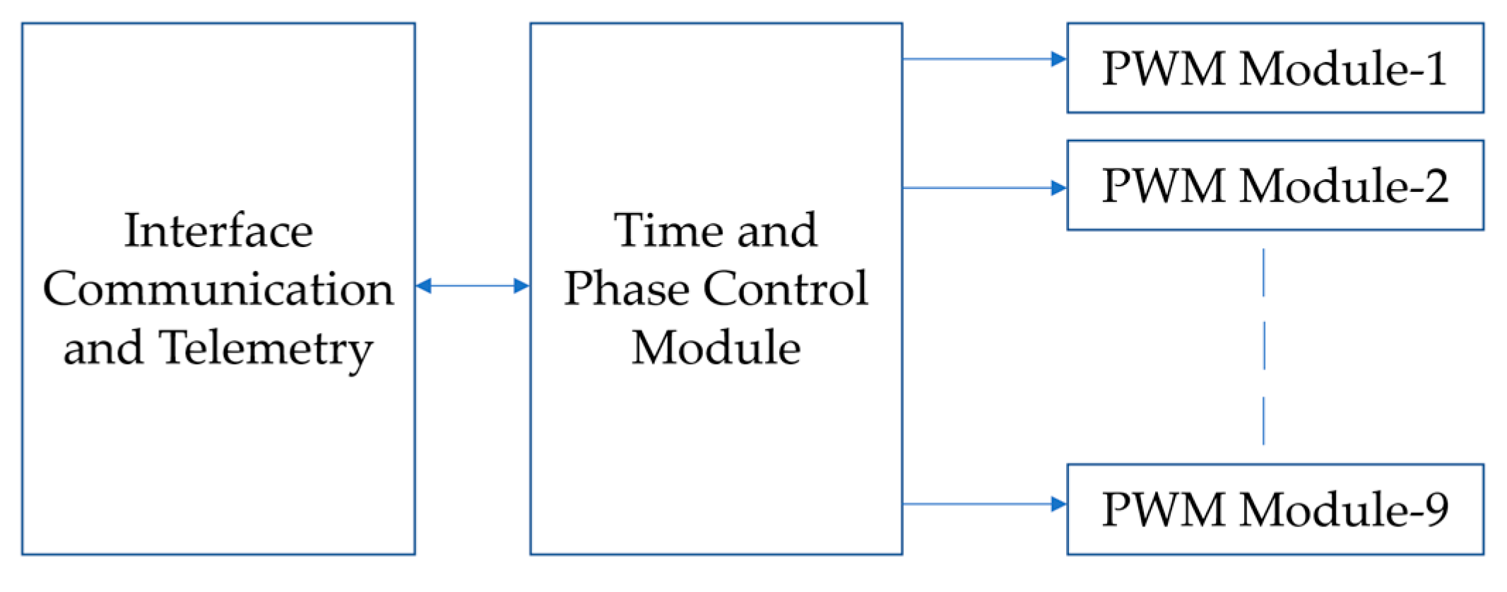
3.2. FPGA Implementation
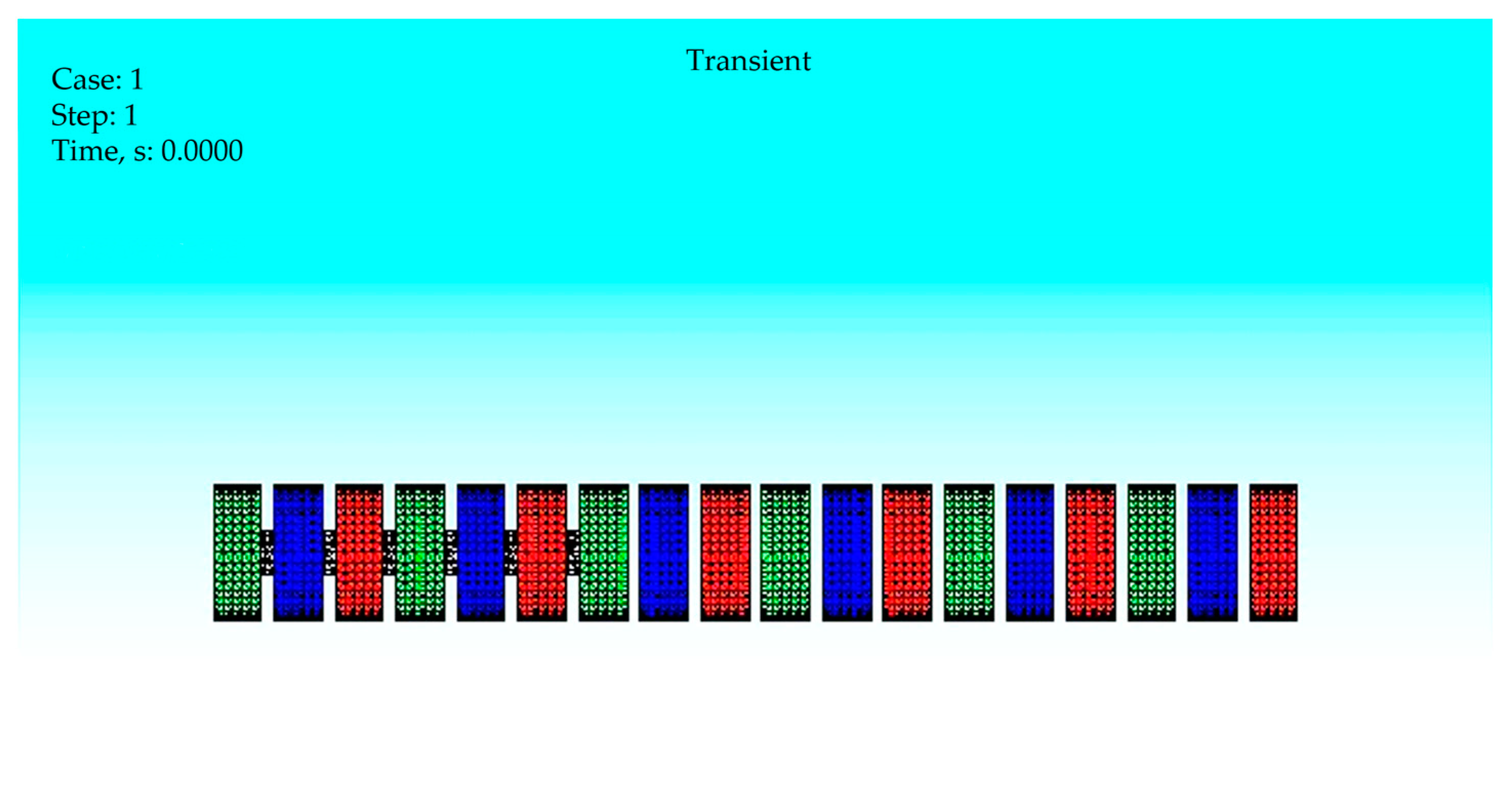
4. Three-Dimensional FEM Analysis
Simulation Results
5. Experimental Study
5.1. Construction of LIL and Power Systems
5.2. Experimental Results
6. Results
7. Discussion
Author Contributions
Funding
Data Availability Statement
Acknowledgments
Conflicts of Interest
Abbreviations
| AC | Alternating Current |
| CSI | Current source inverter |
| DC | Direct Current |
| FEM | Finite Element Method |
| FFT | Fast Fourier transform |
| FPGA | Field-Programmable Gate Arrays |
| GUI | Graphical User Interface |
| IGBT | Insulated-gate bipolar transistor |
| LIL | Linear induction launcher |
| PWM | Pulse-width modulation |
| SiC | Silicon Carbide |
| SPWM | Sinusoidal pulse-width modulation |
| VSI | Voltage source inverter |
| VVVF | Variable Voltage Variable Frequency |
References
- Fair, H.D. Electric Launch Science and Technology in the United States. IEEE Trans. Magn. 2003, 39, 11–17. [Google Scholar] [CrossRef]
- Engel, T.G. Scientific Classification Method for Electromagnetic Launchers. IEEE Trans. Plasma Sci. 2017, 45, 1333–1338. [Google Scholar] [CrossRef]
- Inger, E. Electromagnetic Launching Systems to Geosynchronously Equatorial Orbit in Space and Cost Calculations. IEEE Trans. Plasma Sci. 2017, 45, 1663–1666. [Google Scholar] [CrossRef]
- Fair, H. Electromagnetic Propulsion: A New Initiative. IEEE Trans. Magn. 1982, 18, 4–6. [Google Scholar] [CrossRef]
- Balikci, A.; Zabar, Z.; Birenbaum, L.; Czarkowski, D. On the Design of Coilguns for Super-Velocity Launchers. IEEE Trans. Magn. 2007, 43, 107–110. [Google Scholar] [CrossRef]
- Zabar, Z.; Naot, Y.; Birenbaum, L.; Levi, E.; Joshi, P.N. Design and Power Conditioning for the Coil-Gun. IEEE Trans. Magn. 1989, 25, 627–631. [Google Scholar] [CrossRef]
- Balikci, A.; Zabar, Z.; Czarkowski, D.; Levi, E.; Birenbaum, L. Flywheel Motor/Generator Set as an Energy Source for Coil Launchers. IEEE Trans. Magn. 2001, 37, 280–283. [Google Scholar] [CrossRef]
- Liu, K.; Xiao, Z.; Niu, X.; Zhang, Y. Research of Varying Frequency Driving Scheme for Asynchronous Induction Coil Launcher. IEEE Trans. Plasma Sci. 2017, 45, 1567–1573. [Google Scholar] [CrossRef]
- Gulpinar, F.; Balikci, A. Driving Asynchronous Induction Launchers: Design and Simulation of a Novel Power Conditioner with a Brief Review. Energies 2022, 15, 9360. [Google Scholar] [CrossRef]
- Zabar, Z.; Lu, X.N.; Levi, E.; Birenbaum, L.; Creedon, J. Experimental Results and Performance Analysis of a 500 m/Sec Linear Induction Launcher (LIL). IEEE Trans. Magn. 1995, 31, 522–527. [Google Scholar] [CrossRef]
- Zabar, Z.; Lu, X.N.; He, J.L.; Birenbaum, L.; Levi, E.; Kuznetsov, S.B.; Nahemow, M.D. Test Results for Three Prototype Models of a Linear Induction Launcher. IEEE Trans. Magn. 1991, 27, 558–562. [Google Scholar] [CrossRef]
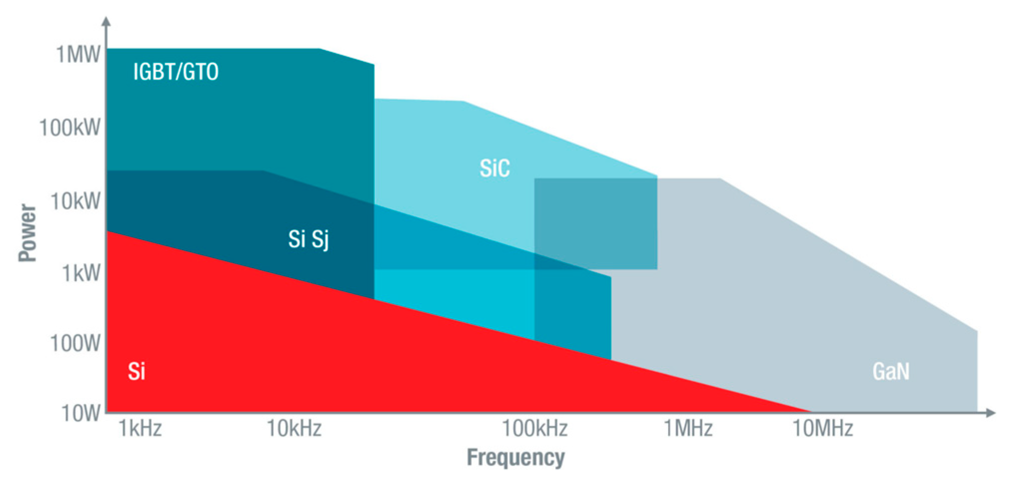
- Pendharkar, S. GaN and SiC Enable Increased Energy Efficiency in Power Supplies. 2018. Available online: https://www.ti.com/lit/SSZY033 (accessed on 15 November 2023).
- Song, M.-S.; Cho, I.-H.; Lee, J.-B. ±180° Discontinuous PWM for Single-Phase PWM Converter of High-Speed Railway Propulsion System. Energies 2020, 13, 1550. [Google Scholar] [CrossRef]
- Qanbari, T.; Tousi, B. Single-Source Three-Phase Multilevel Inverter Assembled by Three-Phase Two-Level Inverter and Two Single-Phase Cascaded H-Bridge Inverters. IEEE Trans. Power Electron. 2021, 36, 5204–5212. [Google Scholar] [CrossRef]
- Lakka, M.; Koutroulis, E.; Dollas, A. Development of an FPGA-Based SPWM Generator for High Switching Frequency DC/AC Inverters. IEEE Trans. Power Electron. 2014, 29, 356–365. [Google Scholar] [CrossRef]
- Lopatkin, N.N. Output Voltage and Current Waveforms’ PSIM Simulation of Three-Phase Seven-Level Cascaded H-Bridge Inverter. In Proceedings of the 2021 International Conference on Electrotechnical Complexes and Systems (ICOECS), Ufa, Russia, 16–18 November 2021; pp. 574–579. [Google Scholar]
- Park, J.S.; Hyon, B.J.; Kim, J.H.; Choi, J.H. Implementation of VVVF Drive for a Three Phase Induction Machine. In Proceedings of the 2016 International Symposium on Power Electronics, Electrical Drives, Automation and Motion (SPEEDAM), Capri, Italy, 22–24 June 2016; pp. 535–540. [Google Scholar]
- Zhou, Z.; Yang, G.; Li, T. Design and Implementation of an FPGA-Based 3-Phase Sinusoidal PWM VVVF Controller. In Proceedings of the Nineteenth Annual IEEE Applied Power Electronics Conference and Exposition (APEC’04), Anaheim, CA, USA, 22–26 February 2004; Volume 3, pp. 1703–1708. [Google Scholar]
- He, J.L.; Levi, E.; Zabar, Z.; Birenbaum, L. Determination of the Parameters of Induction-Type Electromagnetic Launchers. In Proceedings of the 7th Pulsed Power Conference, Monterey, CA, USA, 11–14 June 1989; pp. 602–605. [Google Scholar]
- Hernández, J.A.D.; Carralero, N.D.; Vázquez, E.G. A 3-D Simulation of a Single-Sided Linear Induction Motor with Transverse and Longitudinal Magnetic Flux. Appl. Sci. 2020, 10, 7004. [Google Scholar] [CrossRef]
- Ataseven, I.; Sahin, I.; Ozturk, S.B. Design and Implementation of a Paralleled Discrete SiC MOSFET Half-Bridge Circuit with an Improved Symmetric Layout and Unique Laminated Busbar. Energies 2023, 16, 2903. [Google Scholar] [CrossRef]
- Go, B.-S.; Le, D.-V.; Song, M.-G.; Park, M.; Yu, I.-K. Design and Electromagnetic Analysis of an Induction-Type Coilgun System with a Pulse Power Module. IEEE Trans. Plasma Sci. 2019, 47, 971–976. [Google Scholar] [CrossRef]












| Parameters | Value | |
|---|---|---|
| Barrel | Barrel Length | 0.75 m |
| Number of Coils | 18 | |
| Number of Phases | 3 | |
| Number of Section | 3 | |
| Coil Axial Length | 0.04 m | |
| Coil Inner Radial Width | 0.04 m | |
| Coil Outer Radial Width | 0.09 m | |
| Coil Inductance | 20 uH | |
| Coil Number of Turns | 2 × 10 | |
| Projectile | Length | 0.24 m |
| Inner Radial Width | 0.0038 m | |
| Outer Radial Width | 0.0039 m | |
| Material | Aluminum |
| Parameter | LC Resonance | Generator | Single Inverter | Proposed System |
|---|---|---|---|---|
| V/f control | X | X | √ | √ |
| Section-by-section energization | √ | √ | X | √ |
Disclaimer/Publisher’s Note: The statements, opinions and data contained in all publications are solely those of the individual author(s) and contributor(s) and not of MDPI and/or the editor(s). MDPI and/or the editor(s) disclaim responsibility for any injury to people or property resulting from any ideas, methods, instructions or products referred to in the content. |
© 2024 by the authors. Licensee MDPI, Basel, Switzerland. This article is an open access article distributed under the terms and conditions of the Creative Commons Attribution (CC BY) license (https://creativecommons.org/licenses/by/4.0/).
Share and Cite
Dogangunes, S.; Balikci, A. Design and Implementation of a Linear Induction Launcher with a New Excitation System Utilizing Multi-Stage Inverters. Energies 2024, 17, 1302. https://doi.org/10.3390/en17061302
Dogangunes S, Balikci A. Design and Implementation of a Linear Induction Launcher with a New Excitation System Utilizing Multi-Stage Inverters. Energies. 2024; 17(6):1302. https://doi.org/10.3390/en17061302
Chicago/Turabian StyleDogangunes, Serkan, and Abdulkadir Balikci. 2024. "Design and Implementation of a Linear Induction Launcher with a New Excitation System Utilizing Multi-Stage Inverters" Energies 17, no. 6: 1302. https://doi.org/10.3390/en17061302
APA StyleDogangunes, S., & Balikci, A. (2024). Design and Implementation of a Linear Induction Launcher with a New Excitation System Utilizing Multi-Stage Inverters. Energies, 17(6), 1302. https://doi.org/10.3390/en17061302


