Article

Preliminary Insight into Ice Melting, Surface Subsidence, and Wellhead Instability during Oil and Gas Extraction in Permafrost Region

1
School of Petroleum Engineering, China University of Petroleum (East China), Qingdao 266580, China
2
School of Energy Science and Engineering, Henan Polytechnic University, Jiaozuo 454000, China
*
Authors to whom correspondence should be addressed.
Energies 2024, 17(6), 1292; https://doi.org/10.3390/en17061292
Submission received: 10 January 2024 / Revised: 23 February 2024 / Accepted: 6 March 2024 / Published: 7 March 2024
(This article belongs to the Special Issue New Progress in Unconventional Oil and Gas Development)

Abstract

:
Oil and gas production in permafrost can effectively alleviate energy tensions. However, ice melting around wellbores and the accompanying wellhead instability affect the efficiency and safety of oil and gas development in permafrost. Moreover, the potential oil and gas leakage will damage the environment and the ecology of permafrost. Unfortunately, ice melting, formation subsidence, and wellhead behavior during this process have rarely been investigated in previous studies. In the present work, mechanical properties of permafrost were first experimentally investigated, which provided the basic parameter for subsequent numerical simulation. It was found that the ultimate strength gradually increased with the decreasing temperature, as well as the increasing confining pressure. Meanwhile, although the elastic modulus increased with decreasing temperature, it was less affected by confining pressure. Unlike other parameters, the Poisson’s ratio was hardly affected by temperature and confining pressure. Moreover, both the internal friction angle and the cohesion increased with decreasing temperature, but the influence degree varied within different temperature ranges. Then, ice melting, formation subsidence, and the instability behavior of the wellhead caused by the disturbance of the development operation were numerically explored. The investigation results show that the ice melting range in the reservoir section reached 8.06 m, which is much wider than that in other well sections. Moreover, failure of the cement–permafrost interface, caused by ice melting, resulted in a wellhead sinking of up to 1.350 m. Finally, the insulation effect of the vacuum-insulated casing showed that the temperature drop of the designed vacuum-insulated casing was much lower than that of the ordinary casing. When the fluid temperature within the wellbore was 70 °C, the temperature drop of the designed vacuum-insulated casing was 3.54 °C lower than that of the ordinary casing. This study provides support for maintaining wellhead stability during oil and gas extraction in permafrost for avoiding some environmental disasters (such as oil and gas leakage).

1. Introduction

A scientific assessment of oil and gas resources within the Arctic Circle was conducted by the United States Geological Survey (USGS) in 2009. It was found that the region is rich in oil and gas resources [1,2]. It is estimated that the Arctic Circle has about 30% of the world’s proven natural gas reserves and about 13% of the world’s proven oil reserves [3,4]. However, the permafrost in this area is a temperature-sensitive formation [5,6]. During oil and gas development, the high-temperature reservoir fluid within the wellbore can lead to the melting of permafrost and a reduction in its strength [7,8]. Subsequently, this may threaten both wellhead stability and the safety of engineering operations [9,10,11]. Therefore, it is of great significance to carry out research related to the mechanical properties of permafrost to maintain the stability of wellheads.
Generally speaking, a wellhead system will remain stable under the combined action of lateral and axial loads [12]. Lateral loads mainly consist of ocean current force and the lateral force exerted by the surrounding sediment on the casing [13]. On the other hand, the composition of axial loads is complex. The important components are the buoyant weight of the wellhead system, the lateral support force, and the tip support force between the sediments and the casing [14]. If the loads applied to the wellhead system exceed the bearing capacity of the surrounding sediments, instability of the wellhead system can occur.
A schematic diagram of the stress analysis of a wellhead system is shown in Figure 1. To maintain the stability of the wellhead system in the axial direction, the following conditions should be met [15]:
W c + W w F c + F t
where Wc and Ww are the floating weight of the casing and wellhead system, respectively (N), and Fc and Ft are the lateral and end support force of the sediment on the casing (N), respectively.
The end support force of the casing can be calculated with the following equation:
F t = C b N q + σ v b N r
where (C)b and (σv)b are the effective cohesive force and vertical stress, respectively, at the casing end, and Nr and Nq are dimensionless bearing capacity coefficients.
The lateral static equilibrium equation of the wellhead system can be expressed as:
F w l w = F s l s
where Fw and Fs represent the ocean current force and lateral force exerted by the sediment on the casing, respectively, and Lw and ls are the applied moments of Fw and Fs, respectively.
To date, some progress has been made in research on the mechanical properties of permafrost all over the world. For example, Yang et al. (2015) experimentally studied the mechanical properties of permafrost under high strain rates. They found that temperature, water content, and dry density are three important factors affecting the mechanical properties of permafrost [16]. Bilodeau et al. (2019) attempted to evaluate the creep behavior of permafrost by studying its mechanical properties. The study informed the design and selection of future settlements after permafrost thaws [17]. Wang et al. (2022) experimentally investigated the mechanical properties of thawed unconsolidated deep permafrost and found that its elastic modulus exhibited strong anisotropy [4]. It is well known that these studies are of great value for analyzing geomechanical engineering issues (such as wellhead instability and wellbore collapse) during oil and gas production in permafrost [18]. Unfortunately, all of these investigations were performed at ambient temperatures of around 0 °C, and the minimum or average ambient temperature at the Arctic Circle is generally lower than this [19,20,21]. The mechanical properties at low temperatures are different than those at normal temperatures [8,22]. Therefore, previous investigations on the mechanical properties of permafrost under low-temperature conditions were not thorough enough due to the difficulty with sampling and preservation [19,23]. This is where we can continue to make breakthroughs in the research on the mechanical properties of permafrost.
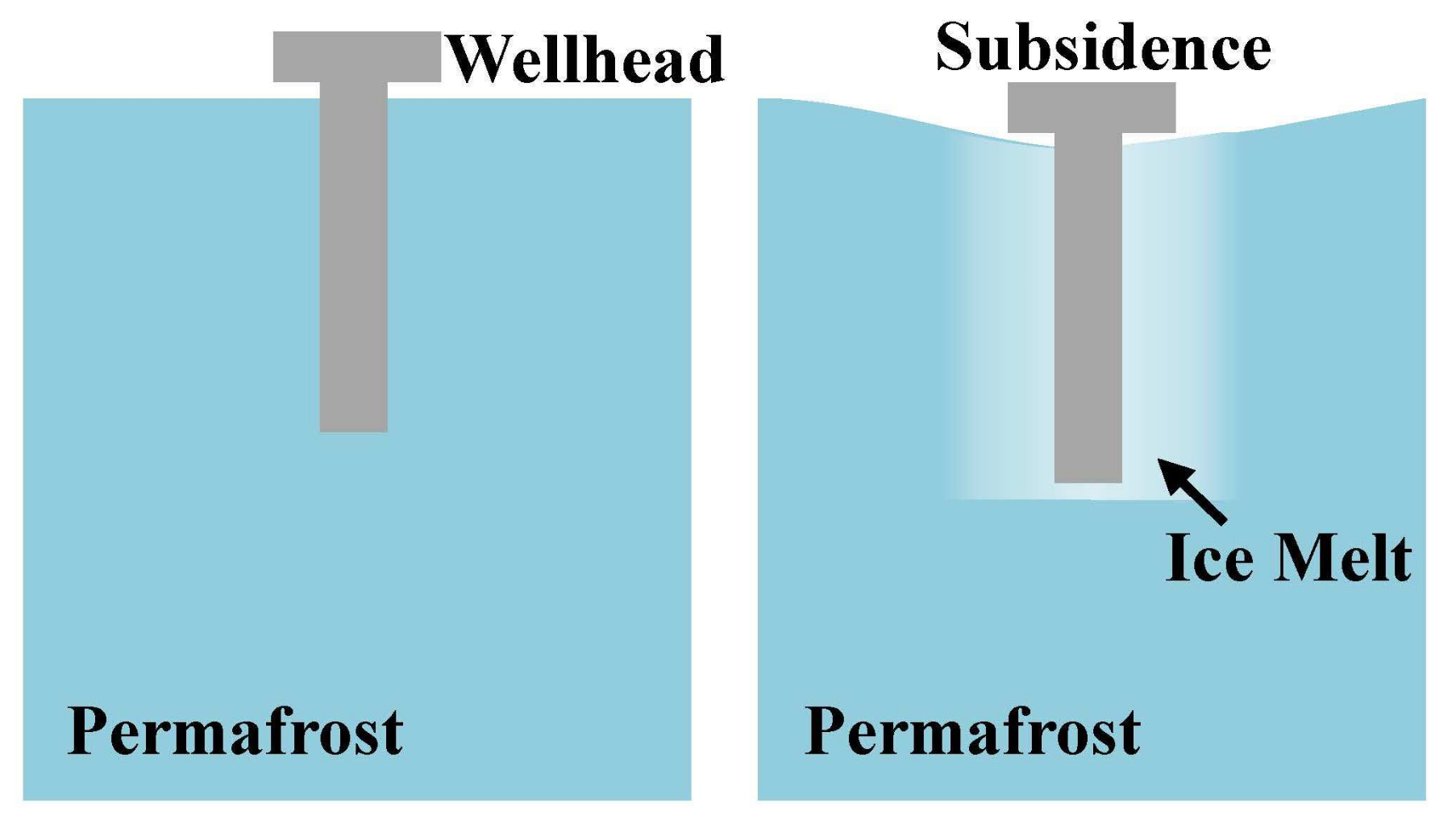
Affected by the disturbance of wellbore fluid (high-temperature reservoir fluid), the permafrost around a wellbore will melt [24,25]. As shown in Figure 2, the bond between the casing and the permafrost will rapidly weaken, leading to subsidence and instability of the wellhead [26,27]. Unfortunately, research on wellhead stability during oil and gas production in permafrost is scarce. Li et al. (2020) analyzed the probability of wellbore settlement in the polar region via numerical simulation [8]. However, the response characteristics of wellhead instability and the corresponding mechanisms have not been revealed. As a result, targeted engineering initiatives cannot be effectively designed and proposed. It is of great significance to investigate the low-temperature mechanical properties of permafrost and explore the response characteristics of wellhead instability based on this.
The Boltzmann method is an important method for conducting numerical simulation studies from a micro-scale perspective to understand the flow behavior of melting water in permafrost. Wei et al. (2018) analyzed the meniscus-induced motion behavior of droplets and bubbles using the Boltzmann method and found that gravity affects the behavior of both bubbles and droplets in porous media [28]. Ji et al. (2022) numerically explored the relative water–gas permeability of hydrate-bearing porous media and carried out multiphase flow simulations at the pore scale using the lattice Boltzmann method. In their investigation, they discovered that the Jamin effect is significant, seriously affecting the multiphase flow characteristics in hydrate-bearing sediments [29]. Wei et al. (2020) analyzed the flow mechanisms of emulsion droplets using pore-scale simulation. They found that there was a trap effect when droplets were flowing through the parallel capillary [30]. Blunt (2001) highlighted some of the major advances in models of wettability and three-phase flow, and found that pore-scale modeling has a huge impact on improving the core analysis and characterization of multiphase flow properties [31]. All of these studies are undoubtedly helpful for analyzing the flow behavior of water in permafrost at the micro-scale level using pore network models.
Inspired by the previous investigations, we studied the low-temperature mechanical properties of permafrost using a self-designed experimental system. In the present work, the effects of temperature and confining pressure were explored. Based on this, the behavior and mechanism of wellhead instability during oil and gas production in permafrost were analyzed. This study is intended to provide a theoretical basis and technical support for the design of engineering measures to avoid accidents from uncontrollable wellhead instability.
The highlights of this study can be summarized as follows:
(1)
The factors affecting the mechanical properties of permafrost in an ultra-low temperature environment (below −20 °C) were studied.
(2)
The influence mechanism of various factors on the mechanical properties of permafrost was explored.
(3)
Wellhead stability during oil and gas development in permafrost was analyzed.

2. Experiments and Methods

2.1. Experimental System

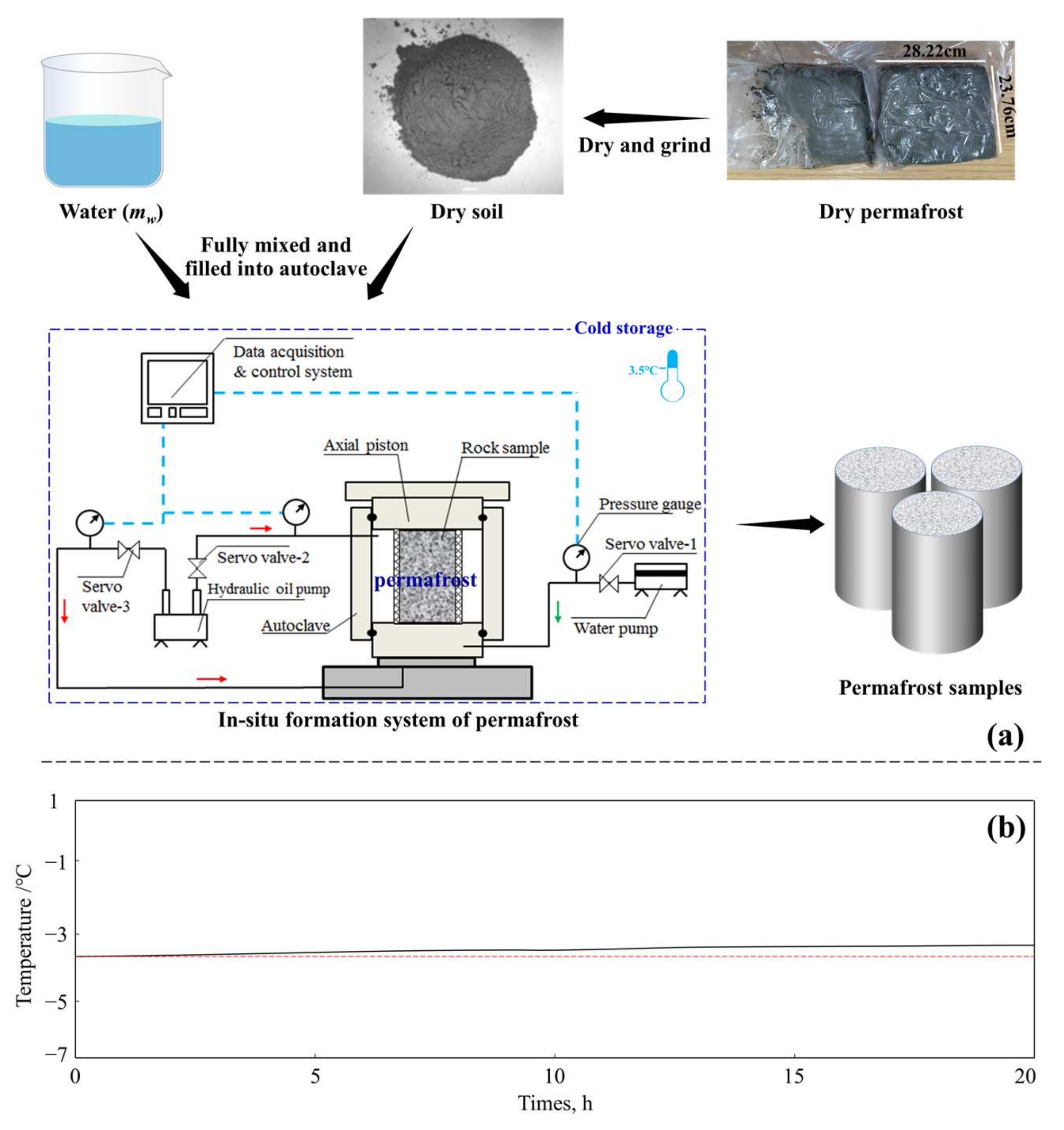
As mentioned above, permafrost samples melt easily, and an experimental investigation of their mechanical properties needs to be carried out in a low-temperature environment. Therefore, a triaxial experimental system was used to explore the low-temperature mechanical properties of permafrost, as shown in Figure 3.
The system is composed of a cold storage unit, a data acquisition and control system, a triaxial experimental machine, and a confining pressure loading system. The cold storage unit and triaxial experimental machine are the two core components. The cold storage unit is a confined space of 4.0 m × 2.5 m × 3.0 m that can fully accommodate the entire experimental system. The cooling limit of the refrigeration equipment is −50 °C. The axial loading limit of the triaxial experimental machine is 100 KN. The maximum confining pressure that the experimental system can load on a sample is 40 MPa. In addition, two strain gauges (deformation limit: 4 mm) are arranged around the sample to measure axial and radial deformation. The axial loading piston is also equipped with a sensor to measure the axial load. The data acquisition and control system can collect and store the stress and strain data obtained during the experiment in real time. The time interval for data collection can be set by the experimental operator, and the minimum collection frequency is 2.5 min/time.

2.2. Experimental Methodology and Materials

The experiment was divided into two steps:
(1)
Remolding of soil samples. As mentioned above, permafrost is difficult and expensive to preserve. In the present work, all permafrost rock samples used for mechanical experiments were artificially prepared. The process of preparing permafrost rock samples is shown in Figure 3. As observed in Figure 3a, samples obtained from the Arctic region need to be fully dried before preparation. The purpose is to ensure that water saturation in prepared permafrost samples meets the design value. Then, crushed permafrost samples need to be fully mixed with distilled water in the preparation tool. At this time, the temperature in the cold storage unit is adjusted to the required value. Importantly, this temperature should be below the freezing point. Samples were prepared by placing the preparation tool on the triaxial experimental machine. The load applied to the rock sample during the preparation process is determined by in situ stress testing, and it should be equal to the overlying pressure (σv). As shown in Figure 3b, when the temperature in the preparation tool remains stable, it indicates that the operation has been completed.
(2)
Measurement of mechanical properties. Confining pressure (corresponding to the horizontal stress at a specific depth) was applied to the outside surface of the sample by a hydraulic oil pump. In this study, the effective confining pressure was set at values of 0, 1.5, 3.0, and 4.5 MPa. Importantly, the confining pressure should be maintained for 6 h until all water in the sample is frozen. After that, the sample is axially loaded at a rate of 0.25 mm/min until shear failure occurs. Stress and strain are recorded in real time through the experimental data acquisition and control system in the experiment. Based on the stress–strain curve, the mechanical parameters of the permafrost samples can be obtained.
In the present work, 16 experiments were conducted on permafrost samples at different temperatures and confining pressures. Accordingly, 16 permafrost samples were prepared for the experiment. The experimental scheme and sample information are given in Table 1.

3. Results

3.1. Ultimate Strength

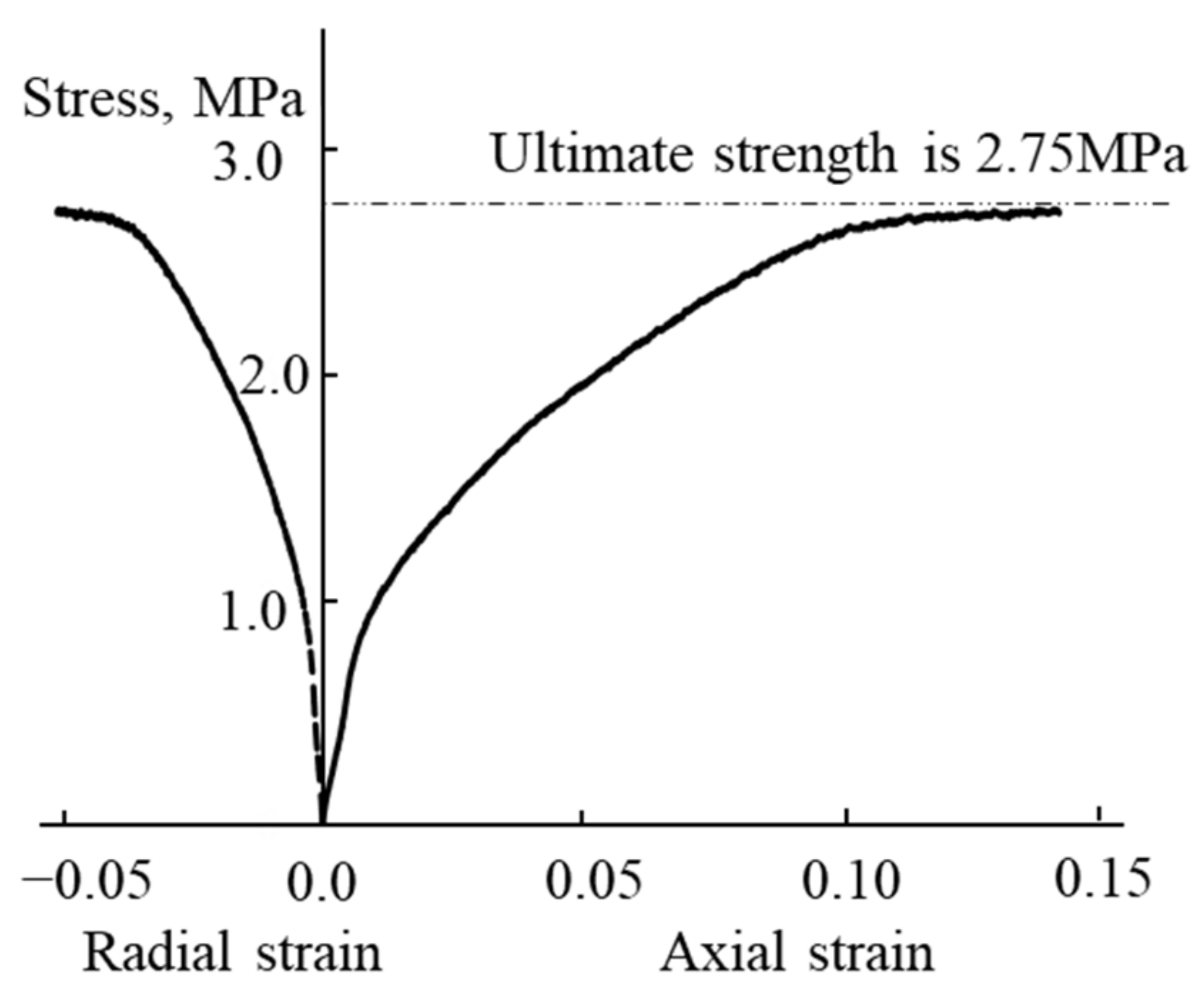
The stress–strain curve is understood to be the basis for investigating the mechanical properties of permafrost. Figure 4 indicates the stress–strain curve of permafrost samples when the confining pressure and temperature are 0 MPa and −10 °C, respectively. As can be observed in the figure, the stress–strain curve of a permafrost sample can be divided into three stages: compaction, elastic deformation, and yield.
As observed in Figure 4, although the stress–strain curve of permafrost exhibits an obvious elastic stage and yield strength, there is no obvious peak strength, let alone brittle failure. Therefore, the concept of ultimate strength is proposed to characterize the bearing capacity of permafrost [32,33]. In fact, it is the asymptote of the highest stress point on the curve. The elastic modulus of the frozen soil rock sample shown in Figure 4 was determined to be 703 MPa, the Poisson’s ratio was 0.35, and the ultimate strength was 2.75 MPa.
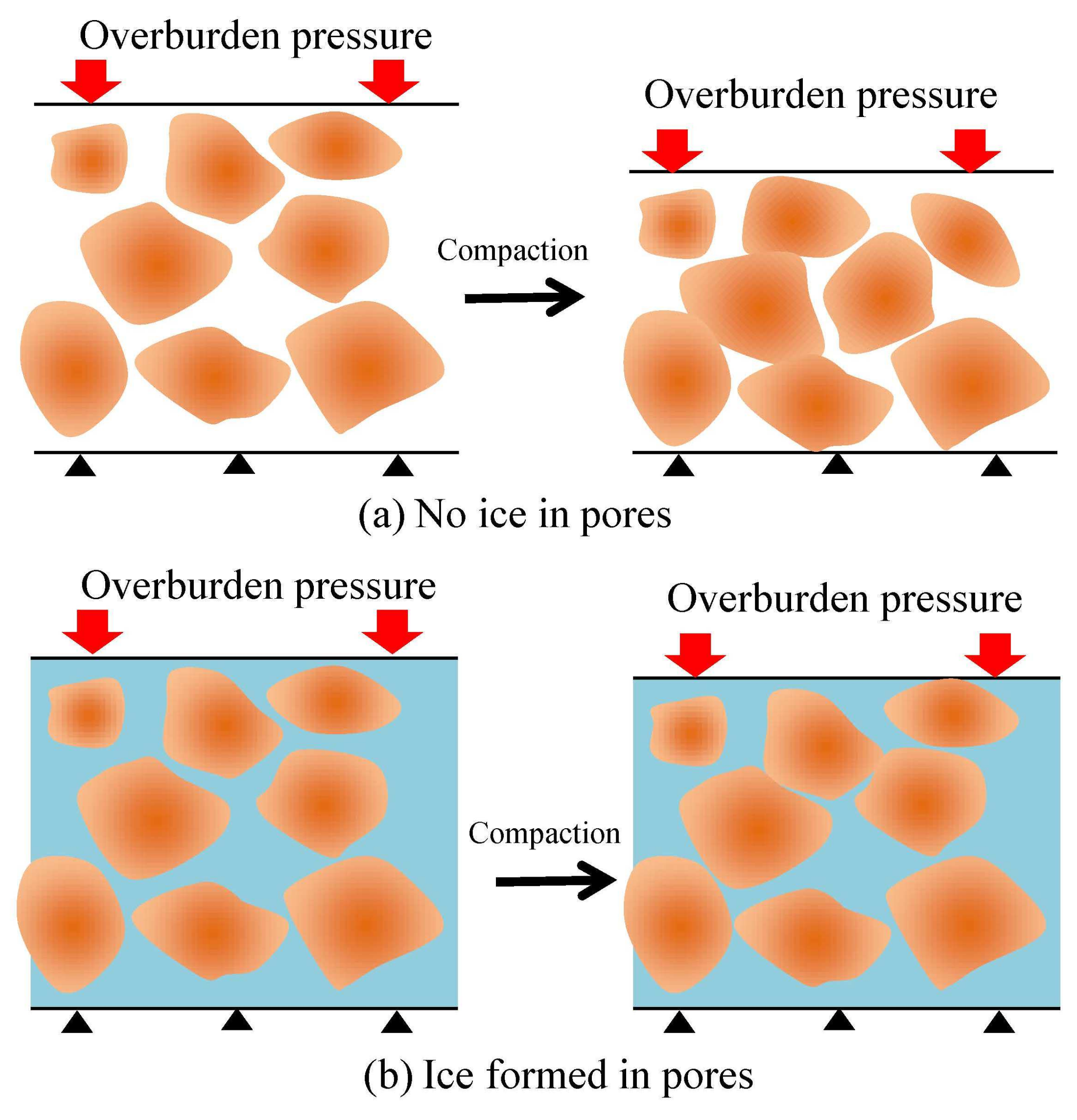
The effects of temperature and confining pressure on the ultimate strength of permafrost are explored in this section, and the results are shown in Figure 5. As observed in Figure 5a, the ultimate strength increases in the form of a power function as the temperature decreases for any confining pressure. Taking a confining pressure of 3.0 MPa as an example, when the experimental temperature decreases from −5 to −25 °C, the ultimate strength increases from 5.12 to 11.56 MPa, amounting to 125.78%. Moreover, for any confining pressure, the ultimate strength increases rapidly with decreasing experimental temperature when the experimental temperature is higher than −10 °C. However, when the experimental temperature is below −10 °C, this trend slows down, and the situation becomes more pronounced as the confining pressure increases. The main reason for this is that when the temperature drops, the unfrozen water in the permafrost gradually undergoes a phase change to form ice (see Figure 6). At the same time, the cementation between ice and permafrost particles gradually increases. Both of these phenomena can lead to a rapid increase in permafrost cohesion, resulting in a significant increase in ultimate strength. In addition, ice gradually forms as the temperature decreases. At lower temperatures, the ultimate strength of permafrost is hardly affected by decreasing temperature.
From Figure 5b, we can see that ultimate strength also increases with increasing confining pressure at any experimental temperature. Taking the experimental temperature of −15 °C as an example, the ultimate strength is only 2.98 MPa when there is no confining pressure. However, it becomes 11.26 MPa when the confining pressure is increased to 4.5 MPa. Furthermore, the trend of ultimate strength increases with confining pressure changes above and below a confining pressure of 3.0 MPa. When the confining pressure is less than 3.0 MPa (temperature is −15 °C), the increase rate of the ultimate strength with confining pressure is 2.18 MPa/MPa. However, when the confining pressure exceeds 3.0 MPa, the increase rate of ultimate strength decreases to 1.17 MPa/MPa. On the one hand, ice in permafrost undergoes a pressure melting effect under high confining pressure. Melting ice deteriorates the cementation between ice and permafrost particles, weakening the strengthening effect of the confining pressure on permafrost. However, when the confining pressure is low, no pressure melting occurs. On the other hand, increased confining pressure makes the permafrost dense (compaction). Therefore, as the confining pressure increases, the opposite effects of permafrost compaction and pressure melting on its strength offset each other to a certain extent.

3.2. Elastic Modulus and Poisson’s Ratio

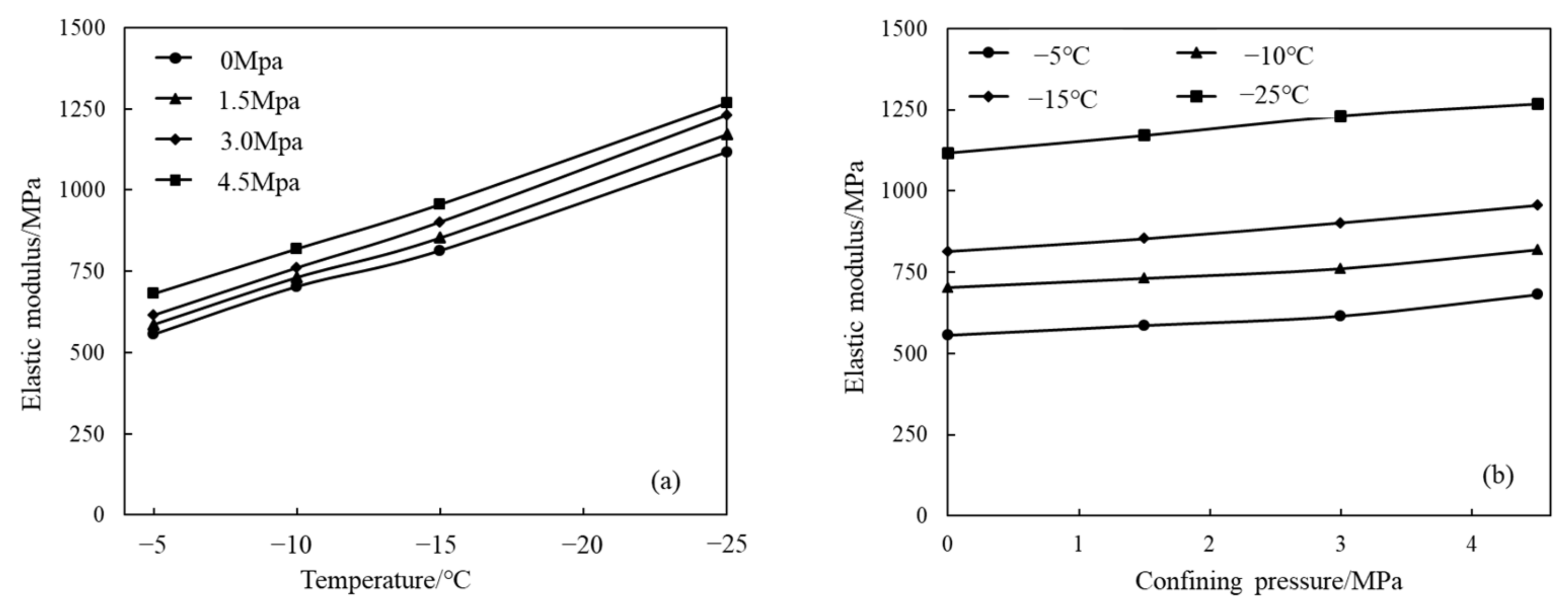
Elastic parameters, such as the elastic modulus, are basic data used to reflect the mechanical properties of permafrost. Figure 7 shows the effects of experimental temperature and confining pressure on the elastic modulus of permafrost. As shown in Figure 7a, the elastic modulus can be substantially affected by experimental temperature under arbitrary confining pressure. The elastic modulus of permafrost increases approximately linearly with decreasing temperature. If the confining pressure is 1.5 MPa, the elastic modulus corresponding to an experimental temperature of −5 °C is 586 MPa. However, when the experimental temperature drops to −25 °C, the elastic modulus increases to 1.171 GPa, nearly double. This can be attributed to the gradual formation of ice in the pores of permafrost at low temperatures. Ice, as the solid phase, can increase the permafrost strength, thereby increasing its overall elastic modulus. If the experimental temperature is lower than this, this effect will be more pronounced.
However, from Figure 7b, it is found that the elastic modulus increases slightly with confining pressure at any experimental temperature. However, the change is not as significant as in Figure 7a. Taking the experimental temperature of −10 °C as an example, the elastic modulus is 731 MPa when the confining pressure is 1.5 MPa. However, it increases to 819 MPa when the confining pressure increases to 4.5 MPa. The elastic modulus of permafrost changes slightly with confining pressure. The pressure melting effect that occurs during the pressure increase can reduce the elastic modulus of permafrost. In addition, due to the compaction caused by increased confining pressure, the elastic modulus gradually increases. For the experimental conditions in this study, the latter effect was slightly stronger than the former. As a result, the elastic modulus of the permafrost exhibited a slight upward trend with increasing confining pressure.
The effects of temperature and confining pressure on the Poisson’s ratio were also analyzed, and the experimental results are displayed in Figure 8. As can be observed in the figure, both the experimental temperature and the confining pressure affected the Poisson’s ratio of the permafrost slightly. The Poisson’s ratio of frozen soil fluctuated between 0.31 and 0.38 for arbitrary experimental temperature and confining pressure, with poor regularity. Thus, the Poisson’s ratio of the permafrost cannot be further discussed in depth herein. Furthermore, the effect of temperature and confining pressure on the Poisson’s ratio of the permafrost can be ignored in subsequent numerical simulation of wellhead stability.

3.3. Cohesion and Internal Friction Angle

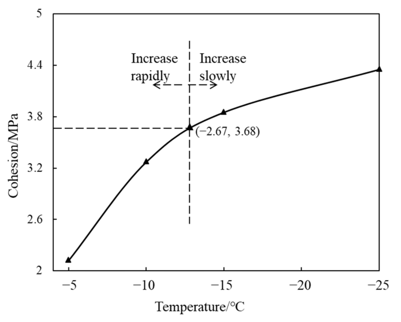
The cohesion and internal friction angle of permafrost can also be affected by various factors, such as temperature, thereby disturbing the stability of wellheads through oil and gas extraction in permafrost. For this reason, the influence of temperature on permafrost cohesion was investigated, and the results are shown in Figure 9.
From Figure 9, we can see that the cohesion of permafrost can be significantly affected by temperature. It increased sharply with decreasing experimental temperature. However, there were differences in the degree of influence of temperature on permafrost cohesion within different temperature ranges. The influence of temperature on permafrost cohesion was significantly stronger when the temperature was higher than −12.67 °C than that when it was lower than −12.67 °C. As observed in Figure 9, the cohesion was only 2.12 MPa when the temperature was −5 °C. However, the cohesion changed to 3.64 and 4.35 MPa when the temperature dropped to −12.67 and −25 °C, respectively. The change rate of cohesion with temperature in the two temperature ranges above and below −12.67 °C were 0.20 and 0.06 MPa/°C, respectively. The reason is that decreasing temperature can freeze the water in permafrost pores, which promotes cementation between particles (see Figure 6). Freezing of pore water can be completed in a low-temperature environment above −12.67 °C. At lower temperatures, there is little pore water available for freezing.
Figure 10 shows the effect of temperature on the internal friction angle of permafrost. Overall, it can be seen from the figure that the internal friction angle of the permafrost increased with decreasing temperature. When the temperature was −5 °C, the internal friction angle was only 9.84°; when the temperature dropped to −25° C, the internal friction angle became 21.92°, an increase of 122.76%. The internal friction angle is a parameter characterizing the friction between particles after cementation failure. Friction between permafrost particles is less affected by temperature; however, the formation of additional ice in pores can increase the internal friction angle at low temperatures.

4. Numerical Simulation of Ice Melting, Surface Subsidence, and Wellhead Stability

4.1. Numerical Model

Based on the experimental results, the instability behavior of a wellhead in permafrost was numerically investigated. It was necessary to make some appropriate assumptions or simplifications before the simulation. Firstly, it was assumed that the forces of ocean current exerted on the wellhead are so small that their effect can be neglected. Secondly, the sediment involved in the investigation model was considered to be homogeneous and isotropic. Finally, the surface was assumed to be flat.

4.1.1. Model Geometry

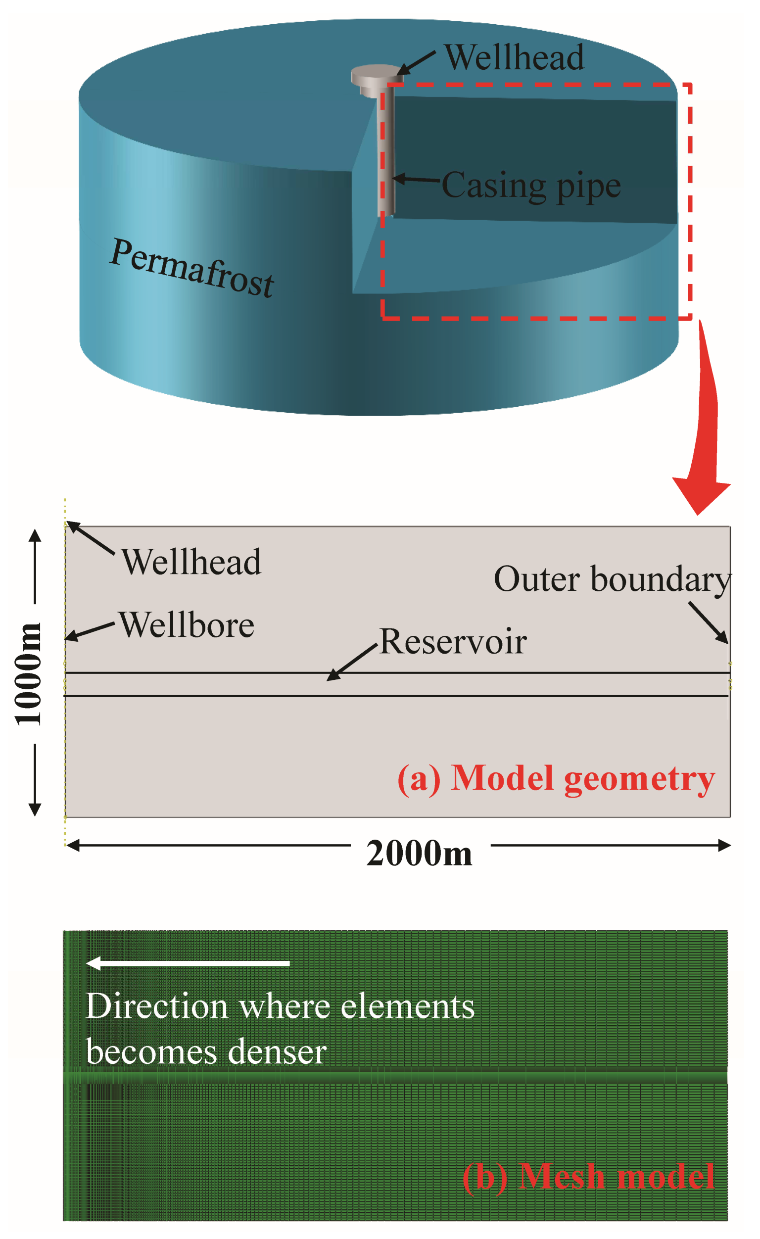
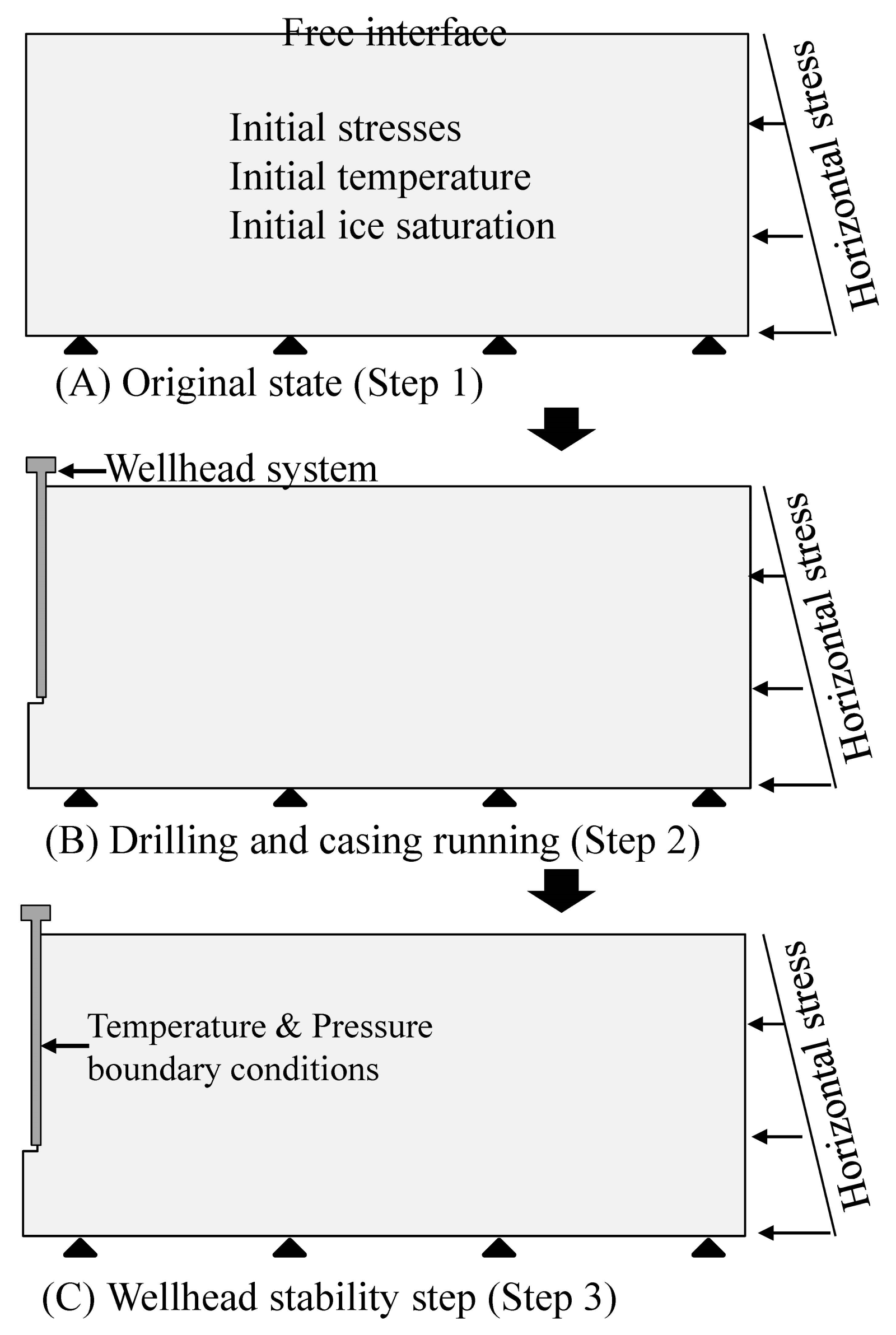
To achieve this goal, an investigation model for analyzing the instability behavior of a wellhead in permafrost was established, and the numerical model is shown in Figure 11. As observed in Figure 11a, the model consists of two components: the permafrost and the wellhead system. The wellhead system consists of the wellhead head and casing, which are interconnected. The model is a cylindrical permafrost deposit with a radius of 2000 m and a height of 1000 m. To save simulation time and cost, the model was simplified to the axisymmetric model shown in Figure 11. In addition, a vertical well with a depth of 600 m was placed in the center of the model.
The mesh model is illustrated in Figure 11b. Melting of ice mainly occurs in the near-wellbore region, and this area was the focus of the present research. As observed in Figure 11b, the element size near the outer boundary is 10 times the element size at the borehole. There are 26,400 CAX4P elements in the permafrost part. This type of element enables simultaneous simulation of reservoir fluid extraction, heat transfer, and sediment deformation during oil and gas development in permafrost. Moreover, the wellhead system is divided into 800 CAX4 axisymmetric stress elements. The model used herein is a fluid–solid–thermal-coupled model.

4.1.2. Simulation Methodology

Compared to the production operation, the drilling cycle is extremely short, and the wellhead is reasonably stable during drilling operation. Therefore, three steps were included in this investigation: step 1, the geostatic step; step 2, the drilling operation step; and step 3, the wellhead stability step. The simulation time for step 2, the drilling operation step, was set as one day, and the simulation time for step 3 was one year. All simulations were conducted in ABAQUS 2016 software, and the simulation workflow of wellhead instability is shown in Figure 12.
In the first two steps, the most important operation is to alternately delete and reactivate the wellhead system and the rock within the wellbore. In ABAQUS 2016, the function that implements this operation is Model Change. In step 1, the wellhead system component is deleted by using the Model Change function to obtain the distribution of in situ stresses, initial pore pressure, initial ice saturation, etc. In step 2, the permafrost elements in the wellbore also need to be deleted by using the Model Change function. At the same time, elements representing the wellhead system are reactivated using the same function to simulate the operation of well completion. In step 3, the pore pressure and temperature boundary conditions need to be applied on the borehole simultaneously. The value of the temperature boundary condition on the borehole should be equal to the temperature of fluid flowing in the wellbore. Correspondingly, the value of the pressure boundary condition on the borehole is equal to the bottom-hole pressure.
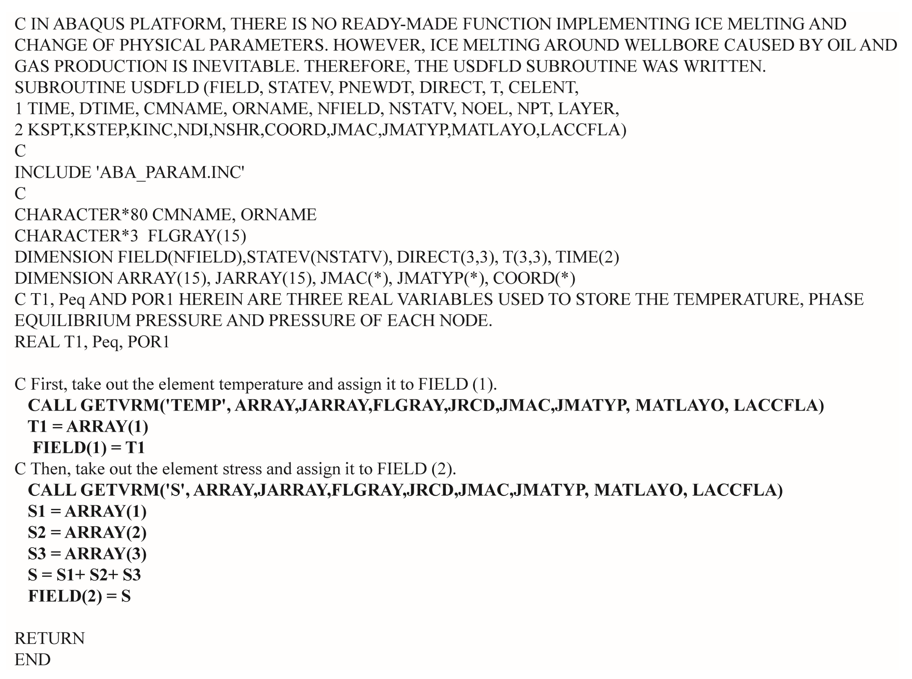
The functions of ice melting and changes in mechanical properties in ABAQUS are implemented using the USDFLD subroutine. The detailed code of the USDFLD subroutine can be found in Appendix A. With this subroutine, the main program can traverse and obtain corresponding mechanical parameters from preset material properties based on the stress and temperature data in the previous increment. The preset material properties in the simulation platform are based on the experimental results shown in Figure 7, Figure 8, Figure 9 and Figure 10.

4.2. Basic Parameters for Investigation

The characteristic parameters of permafrost and the wellhead system are the basic data for simulating the instability behavior of a wellhead during oil and gas production in permafrost. The basic parameters for investigation are given in Table 2. Based on these parameters, the instability behavior and mechanism of the wellhead can be explored.

4.3. Ice Melting and Permafrost Subsidence

Ice melting can lead to a decreased bearing capacity of permafrost, which can affect the stability of wellhead and subsea equipment [34]. In this section, the melting of ice around wellbore and permafrost deformation during the development of oil and gas with a vertical well are analyzed.
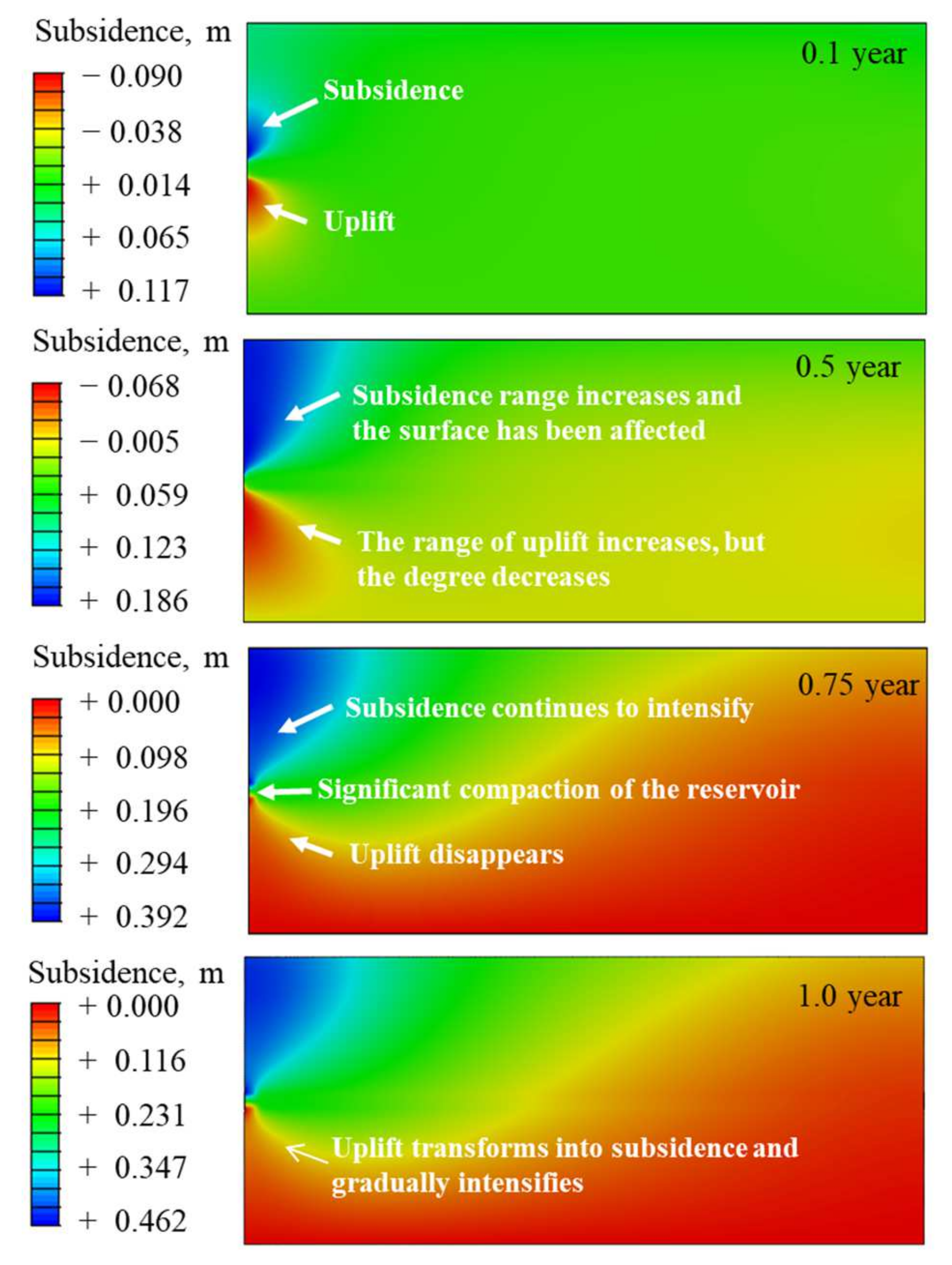
The final contour line of ice melting around a wellbore in permafrost throughout the model depth is shown in Figure 13. As observed in Figure 13, in the overlying permafrost, the melting range of ice gradually increases from the surface, and it rapidly expands near the upper boundary of the reservoir. Ice generally melts to about 2.5 m around a wellbore in the overlying permafrost. In the reservoir section (between 500 and 550 m below the surface), the melting range of ice increases dramatically due to the disturbance of the development operation. The maximum melting range in a reservoir section can reach 8.06 m, which is far wider than that in the overlying permafrost. This is because there are perforations in the casing of the reservoir section that allow communication between the wellbore and the reservoir. In this case, the stability of the ice in permafrost around a wellbore is affected not only affected by heat transfer but also by thermal convection. Except for a small portion near the lower boundary of the reservoir, most of the underlying permafrost does not undergo ice melt. Melting of ice in permafrost will inevitably lead to permafrost deformation and subsidence [35]. A subsidence nephogram during oil and gas extraction from permafrost is shown in Figure 14.
As observed in Figure 14, significant subsidence occurs near the upper boundary of the reservoir in the early stages of development under production conditions. However, a notable uplift occurs near the lower boundary of the reservoir. This can be attributed to the decreased reservoir pressure caused by oil and gas extraction and the increased effective stress leading to reservoir compaction. Reduced strength caused by ice melting may also be partially responsible. When the production operation lasts for 0.1 years, the maximum subsidence near the upper boundary of the reservoir is 11.7 cm, and a maximum uplift of 9.0 cm appears near the lower boundary. As oil and gas production continues, the subsidence near the upper boundary of the reservoir continues to intensify. However, the uplift near the lower boundary of the reservoir gradually weakens and then completely disappears after 0.75 years. During the development process after 0.75 years, permafrost in the whole model exhibits subsidence at a significantly slowed down rate. The reason for this is that the pressure in the model basically stabilizes after 0.75 years of oil and gas production.
An obvious subsidence funnel can also be seen in Figure 14. The maximum surface subsidence of 0.415 m is located near the wellhead. Permafrost subsidence within 150 m of the wellhead on the surface is greater than 0.4 m. Even at a surface location 1500 m horizontally from the wellhead, subsidence is still as high as 0.08 m. Thus, subsea equipment such as the wellhead will also subside or tilt, posing a threat to normal oil and gas development and personnel safety. Therefore, understanding the instability behavior of the wellhead is important for efficient oil and gas extraction in permafrost.

4.4. Instability Behavior of a Wellhead in Permafrost

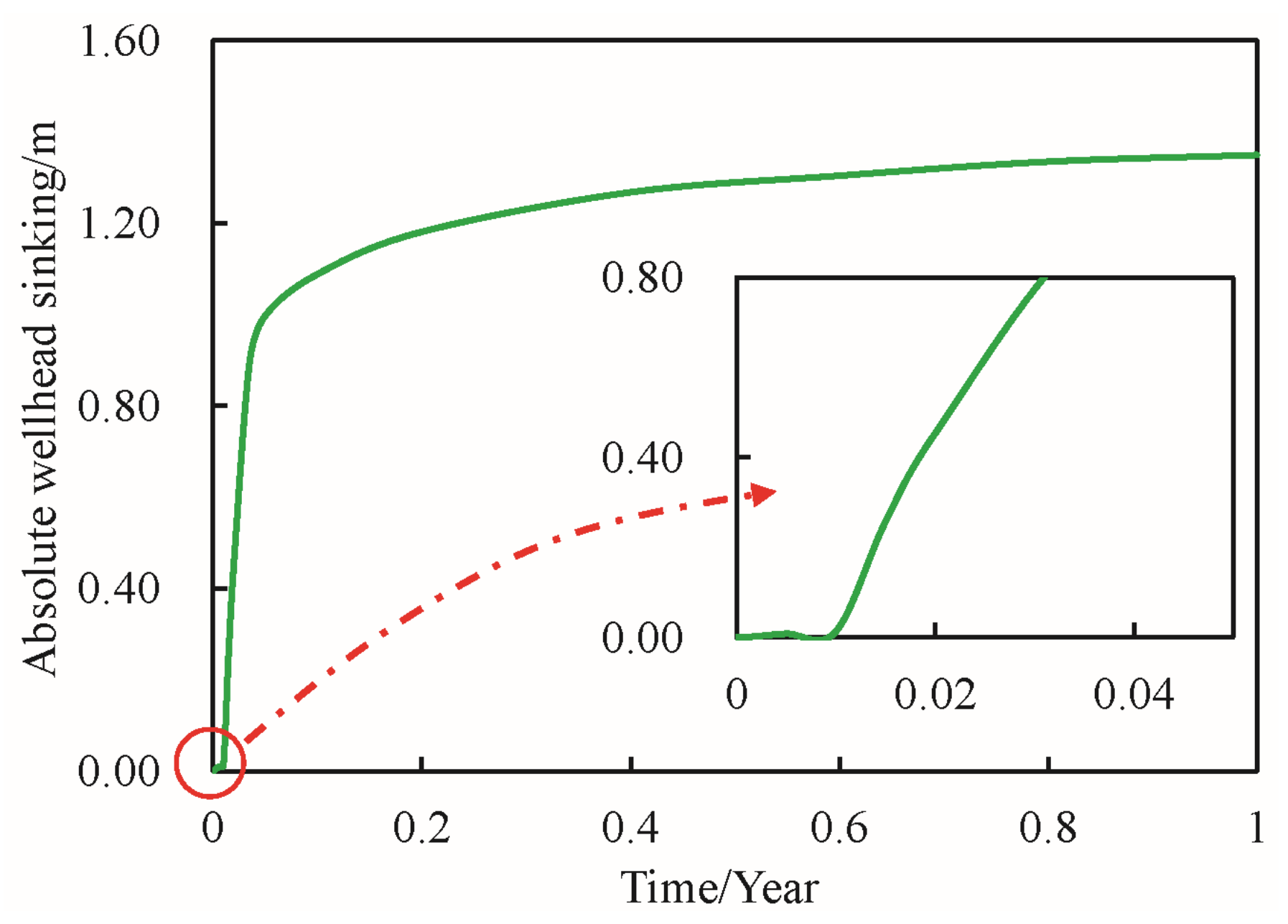
Figure 15 shows the evolution curve of a wellhead sinking during this process. As observed in Figure 15, although the melting of ice is intense in the first 0.01 years, the melting range of ice around the wellbore is narrow. Throughout the entire wellbore section, the cement–permafrost interface (second interface) is intact, and the permafrost has not yet lost its adhesion to the casing. The wellhead is basically stable during this stage, and its stability is mainly affected by the subsidence of the strata. After 0.01 years of development operation, the sinking of the wellhead is only 1.24 cm.
After 0.01 years, the permafrost around the wellbore gradually loses its adhesion and support to the wellhead system. This is attributable to the fact that after 0.01 years, the ice has already melted in a wide range around the wellbore, and the bearing capacity of the permafrost decreases instantly. Sinking of the wellhead is extremely severe between 0.01 and 0.05 years, rapidly increasing from 1.24 to 89.40 cm during this period. However, the maximum permafrost subsidence only increases from 1.24 to 7.86 cm. It can be inferred that significant and gradually strengthening slip instability between the wellbore system and the permafrost occurs during this period. The relative slippage between the wellhead system and the permafrost is 81.54 cm when the development operation lasts 0.05 years.
From that time onward, the support force at the bottom end of the wellhead system gradually replaces the adhesion force of permafrost on the pipe wall to support the wellhead system [36]. The wellhead sinks slowly with the permafrost, and the sinking situation during this period is similar to the permafrost’s subsidence. After 10 years of development, although the final absolute sinking of the wellhead is only 1.350 m, the relative sinking to the surface reaches 0.920 m. Most of the sinking of the wellhead is caused by its sliding instability relative to the permafrost. Therefore, avoiding ice melting and the accompanying decrease in bearing capacity is the key to maintaining wellhead stability during oil and gas development in permafrost. An important measure to solve this problem is to use a vacuum-insulated casing. The subsequent investigation will focus on the impact of vacuum-insulated casing on the stability of a wellbore or wellhead.

4.5. Effect of Model Type on Wellhead Stability

Wellhead stability was investigated using a fluid–solid–thermal (S-F-T)-coupled model, a fluid–solid (S-F)-coupled model, and a pure-solid (S) model. With the exception of the model type, all other investigation conditions were the same. Figure 16 shows the subsidence distribution during oil and gas extraction from permafrost when different types of models are used. As observed in the figure, subsidence and uplift of 26.61 cm appear at the upper and lower boundaries of the reservoir when a pure-solid model is used. However, there is no significant deformation of the seafloor. Figure 16 also shows that there is little difference in the maximum subsidence of the seafloor when the other two models are used. However, reservoir compaction varies significantly. It is clear that reservoir compaction is more pronounced when the fluid–solid–thermal-coupled model is used. This can be attributed to the weaker melting of ice in permafrost in this model. However, when using the fluid–solid–thermal-coupled model, the melting range of ice in permafrost is wide.
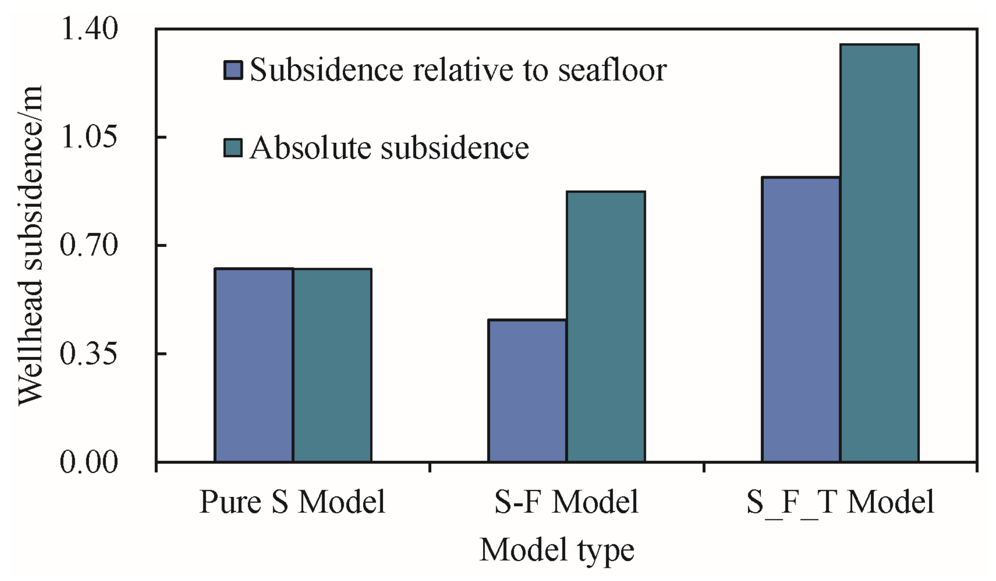
Figure 17 shows a histogram of wellhead subsidence when different types of investigation models are used. As observed in the figure, although the absolute wellhead subsidence is the smallest when a solid model is used, its relative subsidence to the seafloor is still relatively large (0.624 m). This is because the seafloor does not subside in this case. Meanwhile, although the absolute wellhead subsidence is large when the fluid–solid-coupled model is used, the wellhead subsidence relative to the seafloor is small (0.458 m). In this situation, the subsidence of the seabed is severe. The larger absolute wellhead subsidence minus the severer seafloor subsidence will inevitably result in smaller relative wellhead subsidence. When the fluid–solid–thermal-coupled model is used for wellhead stability analysis, the absolute wellhead subsidence and the subsidence relative to the seafloor are both the maximum. From this, it can be seen that ignoring any physical field in the seepage field, temperature field, or deformation field will lead to deviations in the simulation results. For this reason, all three physical fields need to be taken into consideration when conducting numerical investigation of wellhead stability during oil and gas development in permafrost.

4.6. Prevention of Ice Melting and Wellhead Instability in Permafrost

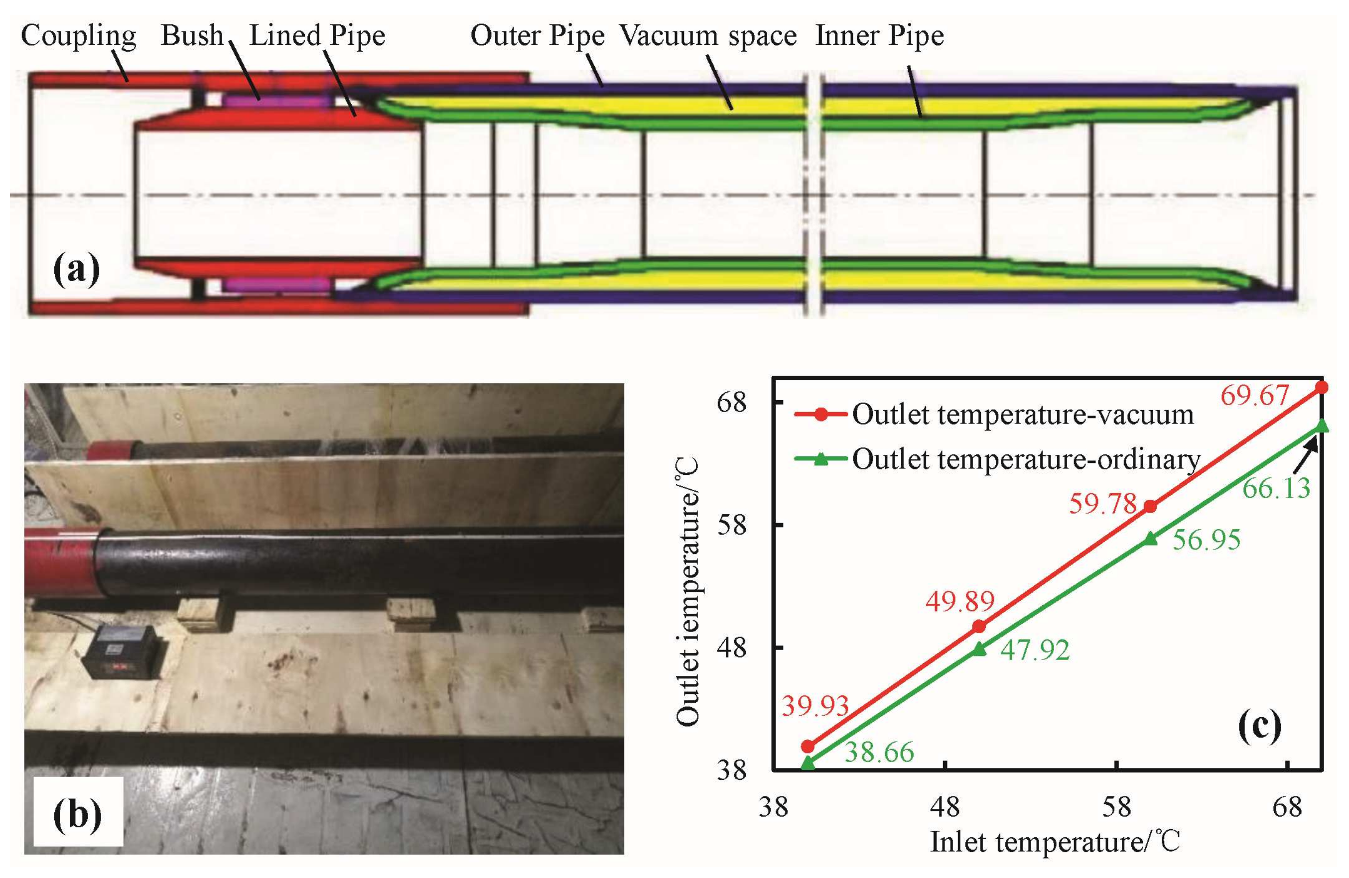
To prevent uncontrollable ice melting and wellhead instability during oil and gas extraction in permafrost, it is necessary to weaken the heat transfer during drilling operations. Therefore, a vacuum-insulated casing was designed and trial-manufactured (see Figure 18). The inner diameter and length of the vacuum-insulated casing are 17.78 cm and 10 m, respectively. Figure 18b indicates that although there is no significant difference in appearance between the vacuum-insulated casing and the ordinary casing, the internal structure actually differs significantly. In reality, this is not the case. The biggest difference between this casing and ordinary casing is its vacuum space (see Figure 18a). As we know, vacuum space can effectively prevent the heat of working fluid inside the pipe from being transferred to the low-temperature outside environment. In this way, disturbance to the environment around the vacuum-insulated casing caused by drilling operations can be greatly weakened.
A preliminary quantitative analysis was conducted to investigate the insulation effect of this type of casing. In the experiment, the casing was always placed in the cold storage unit, where the temperature was maintained at −30 °C. The working fluid at the experimentally designed temperature continuously and uniformly flowed through the casing via the use of an advection pump. Two thermometers at both ends of the casing were used to measure the temperature at the inlet and outlet. The entire pipeline used for circulating the working fluid was insulated.
Figure 18c illustrates the experimental results of the outlet temperature for different inlet temperatures when using the vacuum-insulated casing and the ordinary casing. For the vacuum-insulated casing, the outlet temperature ultimately remained stable at 39.93, 49.89, 59.78, and 69.67 °C when the inlet temperature was 40, 50, 60, and 70 °C, respectively (see Figure 18c). This is attributed to the fact that the temperature difference between the working fluid inside the casing and the ambient temperature is small when the inlet temperature is low. Thus, the heat dissipation is weak. The temperature differences between the inlet and outlet temperatures were 0.07 and 0.11 °C when the inlet temperatures were 40 and 50 °C, respectively. However, the decreased temperature at the outlet compared to the inlet gradually increased with increasing inlet temperature. Despite this, the temperature decrease caused by heat dissipation was still acceptable even when the working fluid temperature was high. The temperature differences between the inlet and outlet temperatures increased to 0.22 and 0.33 °C when the inlet temperatures were 60 and 70 °C, respectively. For comparison, the inlet and outlet temperatures of the ordinary casing were also studied, with all experimental conditions kept the same. The temperature drops (difference between inlet and outlet temperatures) were 1.34, 2.08, 3.05, and 3.87 °C when the inlet temperatures were 40, 50, 60, and 70 °C, respectively. These temperature drops were much larger than those at the corresponding inlet temperatures when the vacuum-insulated casing was used (see Figure 18c). By comparison, the vacuum-insulated casing can effectively reduce the disturbance caused by oil and gas development, affecting the stability of permafrost around the wellbore and wellhead.

5. Conclusions and Future Work

In this study, the mechanical properties of permafrost were experimentally investigated, and the instability behavior of a wellhead was then numerically explored. The main conclusions obtained by numerical and experimental investigations conducted in the present work are as follows:
Except for the Poisson’s ratio, most of the mechanical properties of permafrost were significantly affected by temperature and/or confining pressure. As the temperature decreased, continuous formation of ice in sediment pores enhanced the strength of the permafrost, as well as the cementation between skeleton particles. Specifically, the elastic modulus, cohesion, and ultimate strength all increased with decreasing experimental temperature. Although the increasing confining pressure may have caused some ice to melt (pressure melting effect), it made the permafrost more compacted, resulting in higher strength and stronger cementation. With the increase in confining pressure, the ultimate strength, elastic modulus, and cohesion of permafrost samples demonstrated varying degrees of enhancement. In this way, both ice melting and stress change caused by oil and gas extraction threaten the stability of sediment around the wellhead and the wellbore.
Affected by thermal convection, the melting range of ice in the reservoir section was much wider than in other well sections. The melting range of ice in the reservoir section reached 8.06 m, which is more than three times that of other well sections. The permafrost exhibited a significant subsidence funnel during the investigation process, and the maximum surface subsidence reached 0.415 m. The wellhead was stable in the early stage, but it sank sharply with the failure of the cement–permafrost interface. Interestingly, the wellhead slowly sank with the subsidence of the permafrost in the later stage, and the final absolute wellhead sinking was 1.350 m. Such huge wellhead sinking not only affects the safety of production operations but can also cause oil and gas leakage pollution in the permafrost area.
Moreover, model type is also the important factor affecting wellhead stability. Although the absolute wellhead subsidence was minimal when the pure-solid model was used, its subsidence relative to the seafloor was moderate. However, when the fluid–solid (S-F)-coupled model was adopted, even though the absolute wellhead subsidence was moderate, the subsidence relative to the seafloor was minimal. The reason for this is that the subsidence of the seafloor was also significant in this case. For the fluid–solid–thermal (S-F-T)-coupled model, both the absolute subsidence and the subsidence relative to the seafloor were significant. Therefore, when analyzing the stability of a wellhead during the development of oil and gas from permafrost, it is necessary to consider as many physical fields and factors as possible.
The main drawback of this investigation is that a constitutive model suitable for describing the relationship between the stress and strain of permafrost has not yet been used. This is a breakthrough that needs to be made in the near future based on experimental results. Moreover, it is necessary to explore the thermal conductivity if the vacuum-insulated casing mentioned in Section 4.6 is used for subsequent investigations related to permafrost. In the future work, the following two focuses will be investigated in depth. It is necessary to explore the role of vacuum-insulated casing in preventing ice melting around wellbores, as well as in maintaining wellhead stability and wellbore integrity. In addition, on the basis of existing research, research on factors affecting the formation subsidence and wellhead instability in permafrost can also be carried out.

Author Contributions

Conceptualization, X.Z. and Y.S.; methodology, X.Z.; software, Q.L.; validation, X.Z. and Y.C.; formal analysis, X.Z.; investigation, X.Z. and Y.C.; resources, X.Z.; data curation, Y.C.; writing—original draft preparation, X.Z.; writing—review and editing, X.Z. and Y.C.; visualization, X.Z.; supervision, Y.S. and Y.C.; project administration, X.Z. and Q.L.; funding acquisition, Y.C. All authors have read and agreed to the published version of the manuscript.

Funding

This research was funded by the Program for the National Key Research and Development Program (grant No. 2016YFC0304005), the Henan Provincial Science and Technology Research Project (232102321128), and the Postdoctoral Program of Henan Polytechnic University (grant No. 712108/210).

Data Availability Statement

Data are contained within the article.

Acknowledgments

The conception and launch of this work were also supported by the Rock Mechanics Laboratory (RML) of the China University of Petroleum (East China).

Conflicts of Interest

The authors declare no conflicts of interest.

Appendix A

This is the USDFLD subroutine for implementing ice melting in sediment around wellbores and the resulting changes in mechanical parameters of the permafrost. The code of the USDFLD subroutine is presented in Figure A1.
Figure A1. Codes of the USDFLD subroutine.
Energies 17 01292 g0a1
Figure A2 reveals the clear logic flow of the subroutine that changes material properties in real time based on stress and temperature data.
Figure A2. The logic flowchart of the subroutine.
Energies 17 01292 g0a2

References

  1. Wang, X.; Wang, Z.; Deng, X.; Sun, B.; Zhao, Y.; Fu, W. Coupled thermal model of wellbore and permafrost in Arctic regions. Appl. Therm. Eng. 2017, 123, 1291–1299. [Google Scholar] [CrossRef]
  2. Yakushev, V. Environmental and Technological Problems for Natural Gas Production in Permafrost Regions. Energies 2023, 16, 4522. [Google Scholar] [CrossRef]
  3. Misyurkeeva, N.; Buddo, I.; Kraev, G.; Smirnov, A.; Nezhdanov, A.; Shelokhov, I.; Belonosov, A. Periglacial Landforms and Fluid Dynamics in the Permafrost Domain: A Case from the Taz Peninsula, West Siberia. Energies 2022, 15, 2794. [Google Scholar] [CrossRef]
  4. Wang, J.; Zhang, F.; Yang, Z.; Yang, P. Experimental investigation on the mechanical properties of thawed deep permafrost from the Kuparuk River Delta of the North Slope of Alaska. Cold Reg. Sci. Technol. 2022, 195, 103482. [Google Scholar] [CrossRef]
  5. Chen, P.; Li, R.; Jia, G.; Lan, H.; Fu, K.; Liu, X. A Decade Review of the Art of Inspection and Monitoring Technologies for Long-Distance Oil and Gas Pipelines in Permafrost Areas. Energies 2023, 16, 1751. [Google Scholar] [CrossRef]
  6. Deng, X.; Pan, S.; Wang, Z.; Ke, K.; Zhang, J. Application of the Darcy-Stefan model to investigate the thawing subsidence around the wellbore in the permafrost region. Appl. Therm. Eng. 2019, 156, 392–401. [Google Scholar] [CrossRef]
  7. Kutasov, I.; Eppelbaum, L. The effect of thermal properties changing (at ice-water transition) on the radius of permafrost thawing. Cold Reg. Sci. Technol. 2018, 151, 156–158. [Google Scholar] [CrossRef]
  8. Li, Y.; Cheng, Y.; Yan, C.; Xue, M.; Niu, C.; Gao, Y.; Wang, T. Simulating the effect of frozen soil thaw on wellhead stability during oil and gas drilling operations in arctic waters. J. Cold Reg. Eng. 2020, 34, 04020026. [Google Scholar] [CrossRef]
  9. Cheng, Y.; Xue, M.; Shi, J.; Li, Y.; Yan, C.; Han, Z.; Yang, J. Numerical simulating the influences of hydrate decomposition on wellhead stability. Processes 2023, 11, 1586. [Google Scholar] [CrossRef]
  10. Wan, Y.; Wu, N.; Hu, G.; Xin, X.; Jin, G.; Liu, C.; Chen, Q. Reservoir stability in the process of natural gas hydrate production by depressurization in the shenhu area of the south China sea. Nat. Gas. Ind. B 2018, 5, 631–643. [Google Scholar] [CrossRef]
  11. Sun, J.; Zhang, L.; Ning, F.; Lei, H.; Liu, T.; Hu, G.; Lu, H.; Lu, J.; Liu, C.; Jiang, G.; et al. Production potential and stability of hydrate-bearing sediments at the site GMGS3-W19 in the South China Sea: A preliminary feasibility study. Mar. Pet. Geol. 2017, 86, 447–473. [Google Scholar] [CrossRef]
  12. Wang, Y.; Gao, D.; Wang, J.; Ning, B. Investigation on influence of temperature and pressure on fatigue damage of subsea wellhead in deepwater drilling. J. Pet. Sci. Eng. 2022, 212, 110328. [Google Scholar] [CrossRef]
  13. Wang, Y.; Gao, D. On the static mechanics of the tubular system during installation of the surface casing in deepwater drilling. Appl. Ocean. Res. 2021, 110, 102599. [Google Scholar] [CrossRef]
  14. Xu, Y.; Guan, Z.; Jin, Y.; Liu, Y.; Sun, Y.; Zhang, B.; Sheng, Y. Risk Assessment Method of Subsea Wellhead Instability in Consideration of Uncertain Factors in Deepwater Drilling. Arab. J. Sci. Eng. 2018, 43, 2659–2672. [Google Scholar] [CrossRef]
  15. Li, Q.; Cheng, Y.; Zhang, H.; Yan, C.; Liu, Y. Simulating the effect of hydrate dissociation on wellhead stability during oil and gas development in deepwater. J. Ocean. U China 2018, 17, 35–45. [Google Scholar] [CrossRef]
  16. Yang, Z.; Still, B.; Ge, X. Mechanical properties of seasonally frozen and permafrost soils at high strain rate. Cold Reg. Sci. Technol. 2015, 113, 12–19. [Google Scholar] [CrossRef]
  17. Bilodeau, J.; Verreault, J.; Doré, G. Assessment of the physical and mechanical properties of permafrost in Nunavik, Quebec, Canada. In Proceedings of the 18th International Conference on Cold Regions Engineering and 8th Canadian Permafrost Conference, Quebec City, Canada, 18–22 August 2019; pp. 17–25. [Google Scholar]
  18. Zhang, H.; Cheng, Y.; Li, Q.; Yan, C.; Han, X. Numerical analysis of wellbore instability in gas hydrate formation during deep-water drilling. J. Ocean. U China 2018, 17, 8–16. [Google Scholar] [CrossRef]
  19. Arenson, L.; Johansen, M.; Springman, S. Effects of volumetric ice content and strain rate on shear strength under triaxial conditions for frozen soil samples. Permafr. Periglac. 2004, 15, 261–271. [Google Scholar] [CrossRef]
  20. Romanovsky, V.; Smith, S.; Christiansen, H. Permafrost thermal state in the polar Northern Hemisphere during the international polar year 2007–2009: A synthesis. Permafr. Periglac 2010, 21, 106–116. [Google Scholar] [CrossRef]
  21. Lu, J.; Zhang, M.; Zhang, X.; Pei, W.; Bi, J. Experimental study on the freezing–thawing deformation of a silty clay. Cold Reg. Sci. Technol. 2018, 151, 19–27. [Google Scholar] [CrossRef]
  22. Wang, F.; Liu, X.; Jiang, B.; Zhuo, H.; Chen, W.; Chen, Y.; Li, X. Low-loading Pt nanoparticles combined with the atomically dispersed FeN4 sites supported by FeSA-NC for improved activity and stability towards oxygen reduction reaction/hydrogen evolution reaction in acid and alkaline media. J. Colloid. Interf. Sci. 2023, 635, 514–523. [Google Scholar] [CrossRef]
  23. Yamamoto, Y.; Springman, S. Axial compression stress path tests on artificial frozen soil samples in a triaxial device at temperatures just below 0 °C. Can. Geotech. J. 2014, 51, 1178–1195. [Google Scholar] [CrossRef]
  24. Li, Z.; Spangenberg, E.; Schicks, J.; Kempka, T. Numerical simulation of coastal sub-permafrost gas hydrate formation in the Mackenzie Delta, Canadian Arctic. Energies 2022, 15, 4986. [Google Scholar] [CrossRef]
  25. Melnikov, V.P.; Osipov, V.I.; Brouchkov, A.V.; Badina, S.V.; Sadurtdinov, M.R.; Drozdov, D.S.; Malkova, G.V.; Zheleznyak, M.N.; Zhdaneev, O.V.; Ostarkov, N.A.; et al. Past and future of permafrost monitoring: Stability of Russian energetic infrastructure. Energies 2022, 15, 3190. [Google Scholar] [CrossRef]
  26. Nassr, A.; Esmaeili-Falak, M.; Katebi, H.; Javadi, A. A new approach to modeling the behavior of frozen soils. Eng. Geol. 2018, 246, 82–90. [Google Scholar] [CrossRef]
  27. Guan, J.; Zhang, X.; Chen, X.; Ding, M.; Wang, W.; Yu, S. Influence of seasonal freezing-thawing soils on seismic performance of high-rise cap pile foundation in permafrost regions. Cold Reg. Sci. Technol. 2022, 199, 103581. [Google Scholar] [CrossRef]
  28. Wei, B.; Huang, H.; Hou, J.; Sukop, M. Study on the meniscus-induced motion of droplets and bubbles by a three-phase Lattice Boltzmann model. Chem. Eng. Sci. 2018, 176, 35–49. [Google Scholar] [CrossRef]
  29. Ji, Y.; Kneafsey, T.; Hou, J.; Zhao, J.; Liu, C.; Guo, T.; Wei, B.; Zhao, E.; Bai, Y. Relative permeability of gas and water flow in hydrate-bearing porous media: A micro-scale study by lattice Boltzmann simulation. Fuel 2022, 321, 124013. [Google Scholar] [CrossRef]
  30. Wei, B.; Hou, J.; Sukop, M.; Du, Q.; Wang, H. Flow behaviors of emulsions in constricted capillaries: A lattice Boltzmann simulation study. Chem. Eng. Sci. 2020, 227, 115925. [Google Scholar] [CrossRef]
  31. Blunt, M. Flow in porous media--pore-network models and multiphase flow. Curr. Opin. Colloid. 2001, 6, 197–207. [Google Scholar] [CrossRef]
  32. Li, C.; Brouchkov, A.; Cheverev, V.; Sokolov, A.; Li, K. Emission of Methane and Carbon Dioxide during Soil Freezing without Permafrost. Energies 2022, 15, 2693. [Google Scholar] [CrossRef]
  33. Li, Q.; Liu, J.; Wang, S.; Guo, Y.; Han, X.; Li, Q.; Cheng, Y.; Dong, Z.; Li, X.; Zhang, X. Numerical Insights into Factors Affecting Collapse Behavior of Horizontal Wellbore in Clayey Silt Hydrate-Bearing Sediments and the Accompanying Control Strategy. Ocean. Eng. 2024, 297, 117029. [Google Scholar] [CrossRef]
  34. Etzelmüller, B.; Hagen, J.; Vatne, G.; Ødegård, R.; Sollid, J. Glacier debris accumulation and sediment deformation influenced by permafrost: Examples from Svalbard. Ann. Glaciol. 1996, 22, 53–62. [Google Scholar] [CrossRef]
  35. Mamot, P.; Weber, S.; Schröder, T.; Krautblatter, M. A temperature- and stress-controlled failure criterion for ice-filled permafrost rock joints. Cryosphere 2018, 12, 3333–3353. [Google Scholar] [CrossRef]
  36. Jiao, C.; Niu, F.; He, P.; Ren, L.; Luo, J.; Shan, Y. Deformation and Volumetric Change in a Typical Retrogressive Thaw Slump in Permafrost Regions of the Central Tibetan Plateau, China. Remote Sens. 2022, 14, 5592. [Google Scholar] [CrossRef]
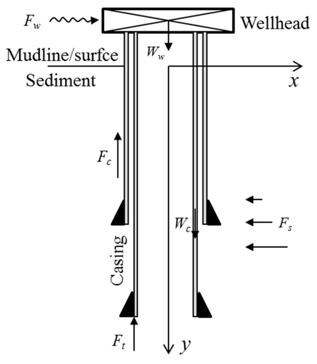
Figure 1. Loads applied to the subsea wellhead system.
Energies 17 01292 g001
Figure 2. Schematic of wellhead instability in permafrost.
Energies 17 01292 g002
Figure 3. Experimental system and preparation process of permafrost rock sample. (a) preparation process; (b) change of temperature during sample preparation.
Energies 17 01292 g003
Figure 4. Stress–strain curve of a permafrost sample.
Energies 17 01292 g004
Figure 5. Effects of temperature (a) and confining pressure (b) on ultimate strength.
Energies 17 01292 g005
Figure 6. Influence diagram of ice formed in the pores of permafrost on its strength.
Energies 17 01292 g006
Figure 7. Influence of temperature (a) and confining pressure (b) on the elastic modulus of permafrost.
Energies 17 01292 g007
Figure 8. Influence of temperature (a) and confining pressure (b) on the Poisson’s ratio of the permafrost.
Energies 17 01292 g008
Figure 9. Relationship between permafrost cohesion and experimental temperature.
Energies 17 01292 g009
Figure 10. Relationship between the internal friction angle of the permafrost and the experimental temperature.
Energies 17 01292 g010
Figure 11. (a) The model geometry for the investigation of ice melting, sediment subsidence, and wellhead stability in permafrost; (b) mesh model.
Energies 17 01292 g011
Figure 12. Simulation workflow.
Energies 17 01292 g012
Figure 13. Final contour line of the ice melting front around the wellbore in permafrost.
Energies 17 01292 g013
Figure 14. Evolution of subsidence distribution during oil and gas extraction from permafrost.
Energies 17 01292 g014
Figure 15. Instability behavior of the wellhead when oil and gas are extracted from the permafrost reservoir.
Energies 17 01292 g015
Figure 16. Subsidence distribution during oil and gas extraction from permafrost when different types of investigation models are used.
Energies 17 01292 g016
Figure 17. Subsidence of the wellhead when different types of investigation models are used.
Energies 17 01292 g017
Figure 18. (a) Structural diagram of vacuum-insulated casing, (b) picture of vacuum-insulated casing, (c) outlet temperature for different inlet temperature when the vacuum-insulated casing and the ordinary casing were used.
Energies 17 01292 g018
Table 1. Experimental scheme and sample information.
No.T, °CPc, MPaD, cmH, cm
1−5024.3251.04
2−1025.0751.43
3−1524.3852.57
4−2525.3753.17
5−51.524.6548.92
6−1024.8252.34
7−1525.3151.67
8−2525.1650.91
9−53.024.4251.37
10−1024.8953.14
11−1525.0952.31
12−2525.1749.88
13−54.524.7851.62
14−1024.9151.33
15−1525.2250.61
16−2524.9349.93
Note: T is temperature; Pc is confining pressure; D is sample diameter; H is sample height.
Table 2. Basic parameters for numerical investigation.
ParametersValue
Elastic modulus/MPaRefer to Figure 7
Poisson’s ratioRefer to Figure 8
Cohesion/MPaRefer to Figure 9
Internal friction angle/°Refer to Figure 10
Permeability/mD2.0
Initial temperature/°C−10 + 3.0 De/100
Pore pressure/MPaρfgDe/106
Ice saturation/%50
Vertical stress/MPaΡpgDe/106
Horizontal stress/MPaΡpgDe/106/B
Thermal conductivity/(W/(m·°C))2.0
Specific heat/(J/(kg·°C))1650
Fluid temperature/°C15
Reservoir depth/m500
Reservoir thickness/m50
Production pressure difference/MPa2.0
Fluid density/(kg/m3)900
Disclaimer/Publisher’s Note: The statements, opinions and data contained in all publications are solely those of the individual author(s) and contributor(s) and not of MDPI and/or the editor(s). MDPI and/or the editor(s) disclaim responsibility for any injury to people or property resulting from any ideas, methods, instructions or products referred to in the content.