Article

Analysis of Fracturing Expansion Law of Shale Reservoir by Supercritical CO2 Fracturing and Mechanism Revealing

1
Exploration and Development Research Institute, Sinopec Jianghan Oilfield Company, Wuhan 430223, China
2
School of Energy Science and Engineering, Henan Polytechnic University, Jiaozuo 454003, China
*
Author to whom correspondence should be addressed.
Energies 2024, 17(16), 3865; https://doi.org/10.3390/en17163865
Submission received: 7 June 2024 / Revised: 19 July 2024 / Accepted: 26 July 2024 / Published: 6 August 2024
(This article belongs to the Special Issue New Progress in Unconventional Oil and Gas Development)

Abstract

:
The rapid expansion of reservoir fractures and the enlargement of the area affected by working fluids can be accomplished solely through fracturing operations of oilfield working fluids in geological reservoirs. Supercritical CO2 is regarded as an ideal medium for shale reservoir fracturing owing to the inherent advantages of environmental friendliness, excellent capacity, and high stability. However, CO2 gas channeling and complex propagation of fractures in shale reservoirs hindered the commercialization of Supercritical CO2 fracturing technology. Herein, a simulation method for Supercritical CO2 fracturing based on cohesive force units is proposed to investigate the crack propagation behavior of CO2 fracturing technology under different construction parameters. Furthermore, the shale fracture propagation mechanism of Supercritical CO2 fracturing fluid is elucidated. The results indicated that the propagation ability of reservoir fractures and Mises stress are influenced by the fracturing fluid viscosity, fracturing azimuth angle, and reservoir conditions (temperature and pressure). An azimuth angle of 30° can achieve a maximum Mises stress of 3.213 × 10⁷ Pa and a crack width of 1.669 × 10⁻² m. However, an apparent viscosity of 14 × 10−6 Pa·s results in a crack width of only 2.227 × 10⁻² m and a maximum Mises stress of 4.459 × 10⁷ Pa. Additionally, a weaker fracture propagation ability and reduced Mises stress are exhibited at the fracturing fluid injection rate. As a straightforward model to synergistically investigate the fracture propagation behavior of shale reservoirs, this work provides new insights and strategies for the efficient extraction of shale reservoirs.

1. Introduction

Fossil fuels, including coal and crude oil, are essential for the sustained development of the global economy and have turned into a driving force behind the progress of human civilization [1,2]. Vast amounts of oil resources are consumed to sustain the growing global economy, and the energy supply structure has gradually shifted towards new energy sources such as wind, solar, and nuclear energy as alternatives [3]. However, the gap left by fossil energy cannot be adequately filled due to numerous shortcomings, including immature transmission methods, inadequate storage techniques, and low conversion efficiency [4]. On account of the high combustion efficiency, similar extraction measures, and unique physical properties, unconventional energy sources have been extensively investigated in the fields of geological exploration, gathering, and transportation methods, and particularly for reservoir stimulation [5,6]. Traditionally, reservoir stimulation has been used to extract crude oil from tight reservoirs to the surface, effectively supplementing conventional energy sources [7,8]. Generally, multiple strategies, including profile control, water plugging, heavy oil viscosity reduction, and acid fracturing, are adopted to improve the oil and gas recovery [9]. As the most widely used and efficient reservoir stimulation measure, fracturing technology applied to geological reservoirs demonstrates a greater sweep coefficient and oil washing efficiency [10].
Water-based fracturing technology, regarded as the savior of underground oil and gas, has demonstrated significant advantages, including high oil recovery efficiency, low cost, minimal reservoir damage, and optimal fracture propagation characteristics [11,12]. The stable physical and chemical properties have enabled the utilization of water-based fracturing technology in the extraction of oil, coal, and other reservoirs. Moreover, the construction process of construction engineering and civil engineering has also been progressively disseminated in accordance with the aforementioned advantages of water-based fracturing [13,14]. However, the emergence of numerous disadvantages has become evident as the inherent limitations of water-based fracturing have gradually become apparent: (1) The rock structure and stress equilibrium state of the reservoir are significantly altered as a consequence of fracturing operations, which will ultimately result in reservoir collapse and ground subsidence [15]. (2) The chemical substances present in water-based fracturing fluids, including cross-linkers (such as zirconium, boron, and chromium) and co-solvents, have the potential to be adsorbed or remain on the surface of or inside reservoir fractures. This can have a significant impact on the balance of the small-scale biosphere, particularly in the context of groundwater contamination and reservoir damage [16]. Moreover, alteration of the subsoil related to collapse and contamination of some hydrocarbon reservoirs can potentially affect livelihoods of substantial communities within their area of influence. (3) A robust water-sensitive effect may be established between the water surface of shale reservoirs and the cross-linker, which directly results in an exceptionally low sweep coefficient and enhanced oil recovery [17,18]. A new high-efficiency fracturing technology that can replace water-based fracturing continues to be explored and improved according to the above defects. CO2 fracturing technology is regarded as a novel reservoir stimulation technique that is anticipated to supersede water-based fracturing.
On account of its excellent fluidity, high stability, and low water sensitivity, Supercritical CO2 fracturing technology has been considered a hotspot and challenging aspect of shale reservoir stimulation [19]. Additionally, CO2 fracturing technology aligns with the relevant policies of carbon capture, utilization, and storage (CCUS), and demonstrates significant potential in mitigating the greenhouse effect and addressing climate change [20]. Changqing Oilfield and Southwest Oil and Gas Field (CNPC) have utilized Supercritical CO2 as the working fluid to extract oil and gas resources from shale reservoirs. Significant data from these oil fields have been collected and interpreted [21,22]. While shortcomings of water-based fracturing technology can be avoided using Supercritical CO2, other disadvantages of Supercritical CO2 still hinder its application in oil fields: (1) Supercritical CO2, with an extremely low apparent viscosity of 0.04 mPa·s, exhibits low crack pressure suppression [23], thereby reducing the crack propagation ability in shale reservoirs. Chemical thickeners, including hydrocarbons, fluorine-containing thickeners, and silicones, can effectively enhance the apparent viscosity and various properties of Supercritical CO2. Although the CO2 thickening capability of the above three thickeners still requires improvement, it has been proven that effective exploration directions are achievable [24,25]. (2) The irregular pattern of crack propagation in shale reservoirs presents another obstacle to the use of Supercritical CO2 fracturing fluid for reservoir stimulation. The direction, width, and pressure distribution of shale fractures, which are markedly different from those formed by water-based fracturing, exacerbate the important obstacles for Supercritical CO2 fracturing fluid in acting on shale reservoirs [26,27]. The expansion of Supercritical CO2 in shale fractures is a critical fact in the exploitation of shale resources.
Herein, the stress–seepage coupling equation was established and utilized to analyze the flow, pressure change, and seepage capacity of Supercritical CO2 fracturing fluid in reservoir fractures. The cohesive element damage criterion is regarded as a crucial basis for describing and simulating crack initiation and propagation. The flow capacity of tangentially flowing Supercritical CO2 fracturing fluid in shale fractures is analyzed using the cubic theorem. Furthermore, a Supercritical CO2 fracturing numerical model of shale reservoirs is employed to analyze the influence of diverse variables on fracture propagation, and the fracture width and Mises stress are identified as pivotal parameters for shale fracture propagation. The objective of this research is to establish an essential reference point regarding the propagation of fractures in shale reservoirs induced by Supercritical CO2 fracturing fluid.

2. Materials and Methods

2.1. Cohesive Element Damage Criterion

Cohesive cracks in quasi-brittle materials, including rocks and cementitious materials, are known to obey the hyperbolic shape criterion, and the expression for this phenomenon is as follows [28]:
F ( σ ) = τ 2 ( C σ n tan φ ) 2 +   ( C σ R tan φ ) 2  
where σR is considered as the tensile strength, Pa; C and φ are the cracking threshold under high normal compressive stresses, Pa; and σn is the shear component, Pa.
A smooth transition from pure normal or shear mode to mixed mode can be achieved using the hyperbolic form of this criterion. Furthermore, the “cohesive crack” model, which employs failure criteria based on hyperbolically shaped surfaces, can be utilized for the analysis of crack propagation in a wider range of materials (Equation (2)) [29]. Additionally, the analysis of normal and shear strength, as well as the evolution of elastic stiffness during damage, can be deduced and revealed.
F ( σ , D ) = τ 2 σ n 2 tan φ 2 + 2 g ( D ) σ n σ c g 2 ( D ) C 2
In which φ represents a friction angle, while σc denotes an auxiliary constant parameter. In addition, the functional relationship among C of complete rock joints, φ and σR of tensile strength, is illustrated in Equation (3) [28]. σc can be well explained and derived through Figure 1a.
σ c = C 2 + σ R 2 tan φ 2 2 σ R

2.2. Crack Initiation Criterion of CO2 Fracturing in Shale Reservoir

The most prevalent fracture initiation methodologies in geological reservoirs are currently the maximum stress criterion, the quadratic strain criterion, and secondary stress criterion. The secondary stress criterion is regarded as the most suitable method for initiating fractures in shale reservoirs, given the geological attributes of unconventional shale reservoirs and the physical properties (7% initial porosity, 2.5 × 10⁻¹⁶ K/m2 permeability, and a 1.2 × 10⁻¹² leak-off coefficient) of CO2 fracturing fluid. The tip of a shale reservoir’s fracture can break through the maximum stress of the reservoir when the sum of the fraction squared between the stresses in the three directions and their respective critical stresses is 1. This finding is supported by Equation (4), which represents the shale cracking model of the secondary stress criterion [30].
< σ n > σ n o 2 + σ s σ s o 2 + σ t σ t o 2 = 1
where σ n o , σ s o , and σ t o represent the critical values of normal stress (Pa), transverse shear stress (Pa), and longitudinal shear stress (Pa), respectively, and the smaller critical value indicates that shale fractures are susceptible to cracking by Supercritical CO2 fracturing fluid. In addition, the self-designed simulation program defines a mixed mode ratio ϕ1 (Equation (5)) to simulate the actual fracture initiation in shale [31].
ϕ 1 = 2 π tan 1 σ s 2 + σ t 2 σ n

2.3. Crack Propagation Criterion of CO2 Fracturing in Shale Reservoir

The process of unit damage evolution in shale fractures is described by considering the degradation of stiffness resulting from the initiation of Supercritical CO2 fracturing fluid in shale reservoirs (Equation (6)).
σ n ¯ = ( 1 D ) σ n ¯ , σ n ¯ 0 σ n = σ n ¯ σ s = ( 1 D ) σ s ¯ σ t = ( 1 D ) σ t ¯
In which σ n ¯ , σ s ¯ , and σ t ¯ are normal stress (Pa) before element damage, shear stress (Pa) before damage in the longitudinal direction, and shear stress (Pa) before damage in the transverse direction, respectively; σ n , σ s , and σ t are considered the actual stresses (Pa) in each direction. In addition, D is a dimensionless constant.
The dimensionless damage factor D [32] was calculated using Equation (7), which is based on the linear displacement expansion criterion.
D = d m f ( d m max d m o ) d m max ( d m f d m o )
where d m o , d m f , and d m max represent the displacement amplitude during initial damage, damage deformation, and complete destruction.

2.4. Flow and Stress of Supercritical CO2 in Shale Fractures

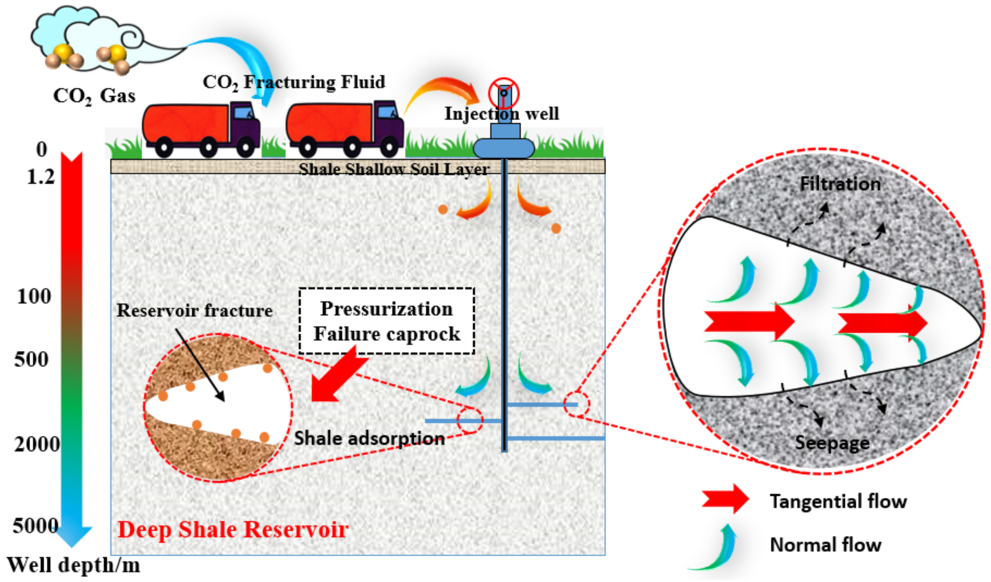
The application of Supercritical CO2 in shale fractures has been observed to result in the generation of both tangential and normal flow patterns. The implementation of Supercritical CO2 with a high degree of tangential flow has been demonstrated to facilitate the growth and expansion of existing cracks. In addition, the width of the cracks mainly relied on the predominant normal flow of Supercritical CO2 (Figure 2). Moreover, the initiation and propagation of reservoir fractures are also affected by rock composition, and the influence of rock composition on reservoir fracture parameters will be subsequently discussed and explained in detail.
The flow of Supercritical CO2 fracturing fluid in shale fractures is governed by the cubic theorem (Equation (8)), which is a consequence of the fluid’s Newtonian properties and low viscosity [33].
q = d 2 12 μ p
where q represents the density vector for volumetric flow rate, m/s. d denotes a crack opening width, m. μ is the viscosity coefficient of Supercritical CO2, and ▽p signifies the Supercritical CO2 pressure (Pa). As can be observed from Equation (8), a proportional relationship was identified between crack opening width and fracturing fluid viscosity. In addition, the seepage and fluid filtration characteristics of Supercritical CO2 are also a consequence of the permeability of shale reservoirs. Equation (9) demonstrates a normal flow of Supercritical CO2 through reservoir fractures.
q t = c t ( p i p t ) q b = c b ( p i p b )
where q t and q b are the fluid flow velocities on the upper and lower sides of the reservoir fracture, m/s. c t and c b represent the filtration coefficients on the upper and lower sides, m3·min1/2. p t and p b are the fluid pressures of Supercritical CO2, Pa.

2.5. Fracturing Model of Supercritical CO2 in Shale Fractures

The 2D model for fracturing shale reservoirs with Supercritical CO2 fracturing fluid, as presented in this study, is based on the cohesive module of the cohesive unit (Figure 3). This investigation led to the establishment of a two-dimensional CO2 fracturing mesh model comprising 18,500 CPE4P elements, which is dedicated to simulating the CO2 fracturing process with the oriented perforation. In addition, the mesh refinement, particularly in the near-wellbore formation, was used to enhance the model convergence and the stability of fracturing process. As illustrated in Figure 3, an injecting point for the fracturing fluid is positioned at the geometric center of the shale reservoir. The maximum principal stress in the y direction is 10 MPa, while the minimum principal stress of 8 MPa is shown in the x direction. Moreover, Table 1 presents the common physical parameters of 2D models of shale reservoirs. Herein, the crack propagation is analyzed using the parameters of crack width (PFOPEN) and Mises stress.

3. Results and Discussion

3.1. Effect of CO2 Fracturing Fluid Viscosity on Shale Fracture Propagation

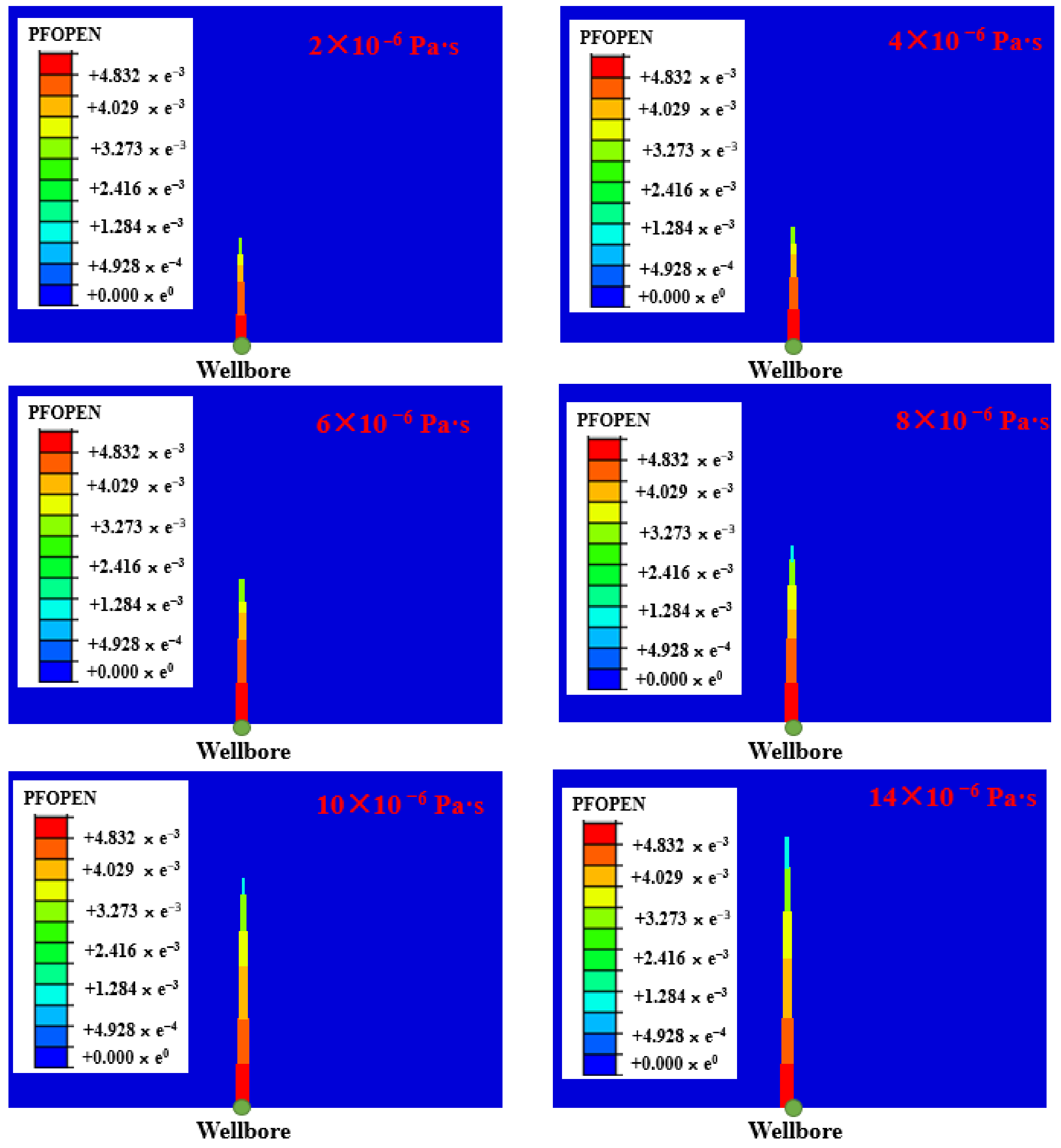
It is widely acknowledged that the shale fracture expansion and fracturing efficiency are influenced by the viscosity of various fracturing fluids (especially Supercritical CO2 fracturing fluid). However, a comprehensive analysis of the fracture propagation rules associated with Supercritical CO2 fracturing fluid is lacking in the existing literature. Consequently, it is essential to investigate the damage evolution of shale fractures caused by the apparent viscosity of Supercritical CO2 [34]. Figure 4 shows the effects of CO2 viscosity on the crack shape, crack width, and Mises stress. It can be seen from Figure 4 that the crack width and length increase gradually with an increase in the apparent viscosity of Supercritical CO2, but a significant difference in crack propagation is demonstrated when CO2 fracturing fluids have different apparent viscosities [35].
As illustrated in Figure 5, the use of a Supercritical CO2 fracturing fluid with an apparent viscosity of 2 × 10⁻⁶ Pa·s resulted in the light propagation of shale fractures, with a length of 4.5 m and a width of 4.85 × 10⁻³ m. In addition, the apparent viscosity of 4 × 10⁻⁶ Pa·s only exhibited a slightly larger expansion capacity of shale fractures than that of 2 × 10⁻⁶ Pa·s. However, a shale fracture rapidly spread with the apparent viscosity of Supercritical CO2 exceeding 6 × 10⁻⁶ Pa·s, and an obvious positive exponential relationship was shown among CO2 viscosity, crack length, and crack width. Moreover, when the CO2 fracturing fluid with an apparent viscosity of 14 × 10−6 Pa·s interacts with shale fractures, it exhibits a pronounced positive proportional relationship with both the fracture width and fracture length. The changing trend shown in Figure 5 can be described and analyzed by Equation (8), which shows that the capacity of a fracturing fluid at a constant flow rate to propagate reservoir fractures increases with the apparent viscosity. In addition, it can be observed from Equation (8) that a smaller CO2 pressure (▽p) is exhibited in shale reservoir fractures when the CO2 viscosity(μ) is larger. This phenomenon may result from the leakage and seepage of the CO2 fracturing fluid [36]. The seepage and filtration of CO2 caused the growth trend of fracture width to be significantly weaker than that of fracture length.
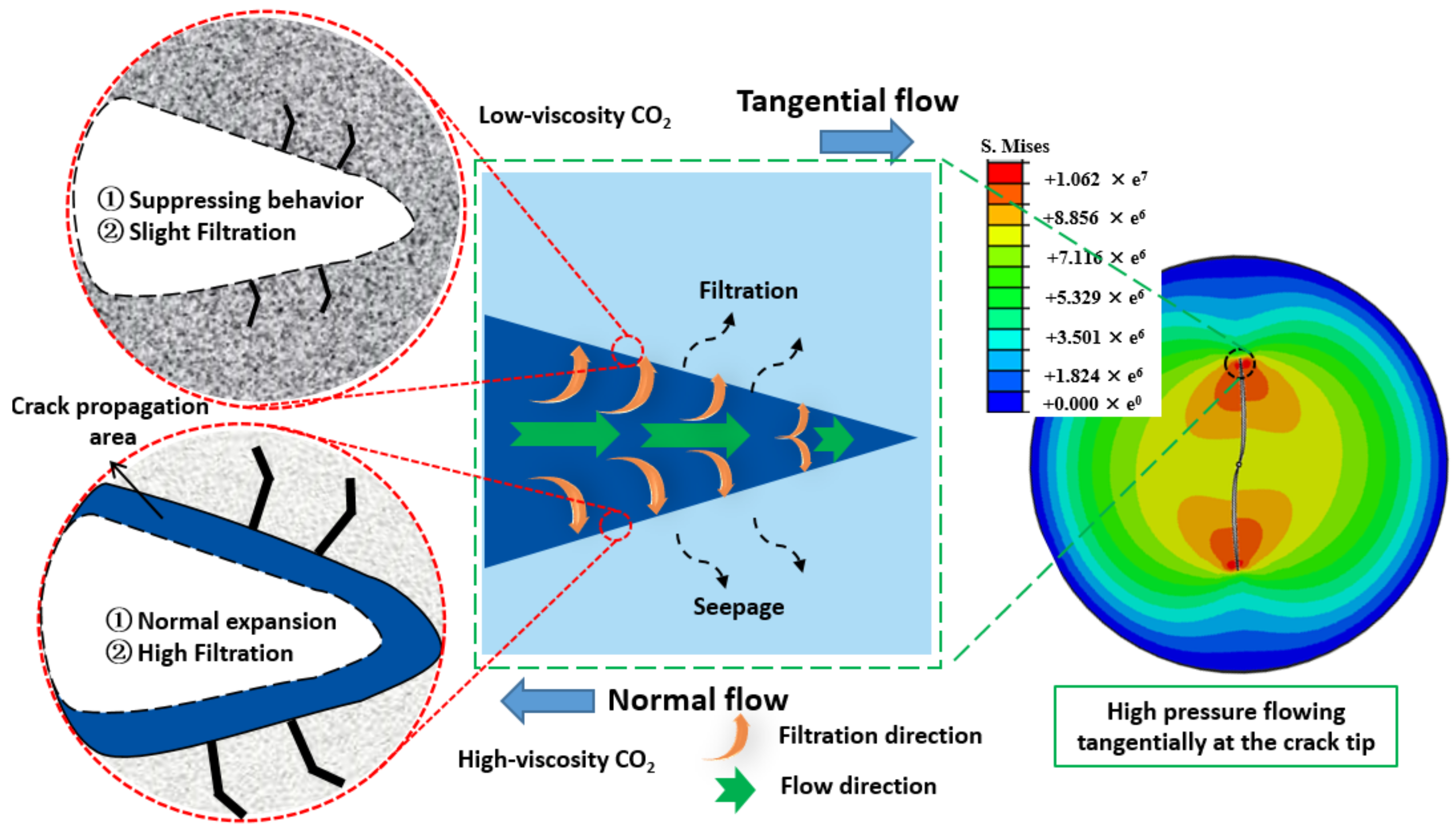
As shown in Figure 6, Supercritical CO2 fracturing fluid can emerge the filtration and seepage into shale reservoirs when flowing in the normal flow direction. The low-viscosity CO2 results in a reduction in fracture width d and an increase in fluid pressure ▽p, while a stable low rate of the Supercritical CO2 fracturing fluid was observed in Equation (8) [37]. Supercritical CO2 with extremely low viscosity precludes its penetration into the minute fissures surrounding the fissure, which in turn gives rise to the uninterrupted accumulation and pressure of Supercritical CO2 within the shale fractures. Almost no Supercritical CO2 is lost and seeps into shale reservoirs, and the minimum fracture initiation pressure required to break through the reservoir pressure is achieved by the increasing CO2 pressure ▽p [38]. Nevertheless, a rapid increase in crack width (d) results in a continuous decline in CO2 pressure (▽p), while the apparent viscosity of Supercritical CO2 exhibits a gradual increase. Low fluid pressure at high CO2 viscosity is primarily attributable to the high percolation and filtration processes associated with normal flow. Furthermore, the CO2 fracturing fluid that flows tangentially will gradually move towards the crack end. The Supercritical CO2 released by the crack initiation will result in a reduction in CO2 pressure.
The stress distribution at the crack tip in Figure 6 and Figure 7 provides a more comprehensive illustration of the aforementioned reasons. The Mises stress distribution of a shale reservoir fracture that has been fractured to a certain length allows for the clear observation of the stress difference around the fracture. It also demonstrates the extreme tangential stress (Mises stress) concentrated at the top of shale fractures. Additionally, the reservoir stress is shown to gradually decrease as the stress position approaches the injection point of CO2 fracturing fluid [39]. It can be considered that the pressure at the crack tip (Mises stress or tangential pressure) is markedly elevated in comparison to the pressure on both sides of the crack (normal pressure). The tangential pressure at the crack tip simultaneously contributes to the initiation of shale fractures, indicating that the crack initiation process occurred at an earlier stage than the subsequent fracture width expansion [40]. In addition, the pressure surrounding the crack illustrated in Figure 7 increased in conjunction with increasing CO2 viscosity. This correlation is in accordance with the expansion relationship of the crack depicted in Figure 6. Concurrently, the accelerated growth rate of tip pressure (Mises stress) also induced the larger exponent (0.18) of the seam length curve depicted in Figure 6, and a diminished change in crack width and exponential value (0.16) was also generated due to the gradual alterations in normal pressure. In summary, the apparent viscosity of Supercritical CO2 fracturing fluid has been identified as a promising avenue of exploration for effectively initiating and rapidly expanding shale fractures.

3.2. Effects of Mineral Properties on Reservoir Fractures

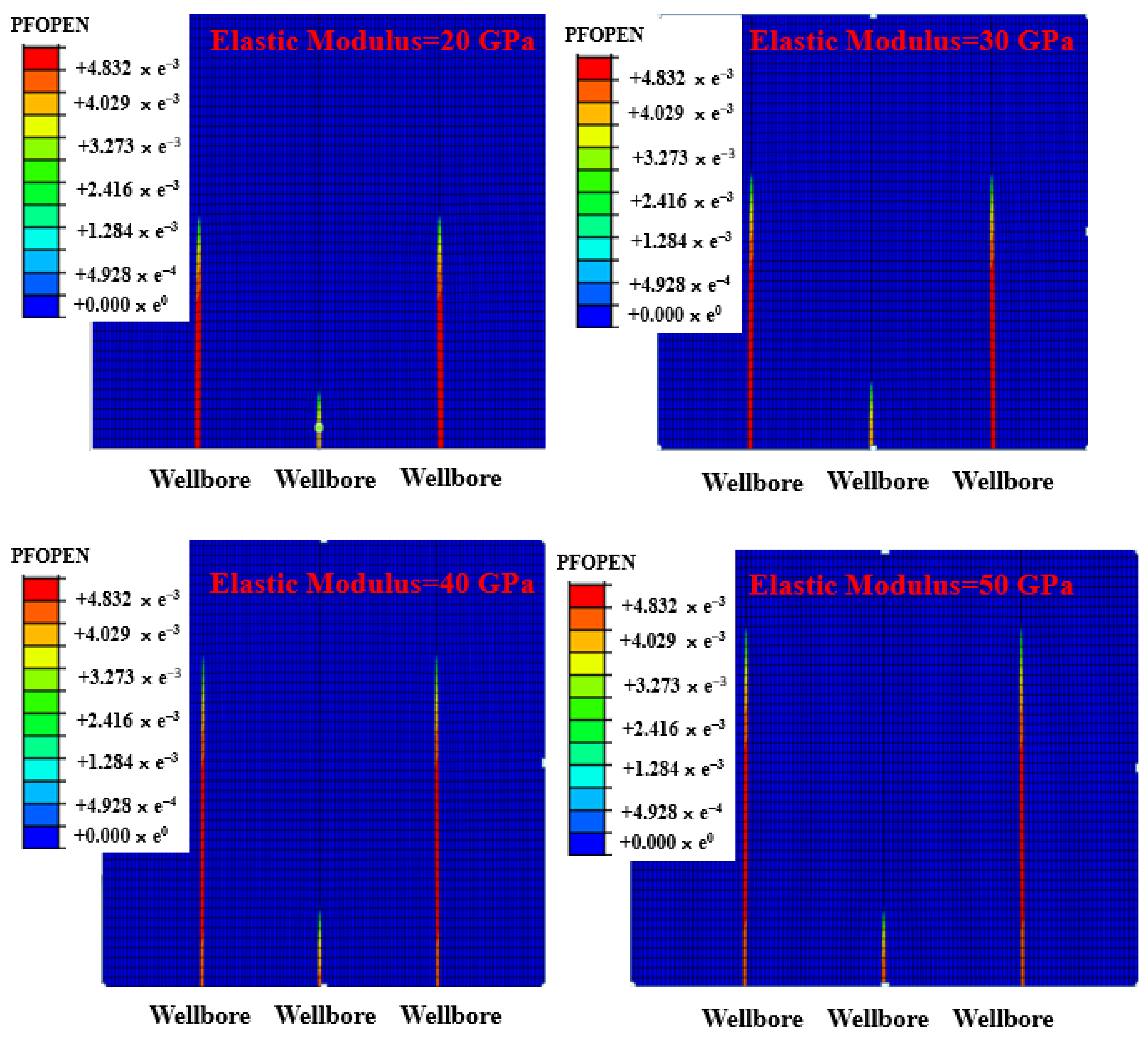
The mineralogical characteristics of shale rocks, including chemical composition, internal structure, and hardness, exert a considerable influence on the inception and propagation of reservoir fractures. Nevertheless, the limitations of parameter configuration based on model-building software are centered on the examination of the impact of rock hardness (rigidity or elastic modulus) on the inception and propagation of shale fractures. It can be seen from Table 2 and Figure 8 that a significant direct proportional relationship between the elastic modulus and crack parameters is presented. The crack length continued to increase with the increase in the rock elastic modulus, and the crack length of 12.3 m at a 20 GPa elastic modulus is much higher than that of a 30 GPa elastic modulus. A relatively small increasing trend is shown when the elastic modulus is below 30 GPa, but the elastic modulus of 40 GPa resulted in a very large crack growth. Nevertheless, the crack width tends to diminish in proportion to the rise in elastic modulus, thereby establishing a highly significant inverse correlation between the two variables. An elastic modulus of 20 GPa has been demonstrated to result in a crack width of 2 × 10⁻² m, a value that is significantly larger than that observed for an elastic modulus of 30 GPa. Furthermore, the crack width diminished at a considerable rate when the elastic modulus was in excess of 30 GPa. While an elevated elastic modulus can facilitate the expansion of shale fissures, a reduction in crack width increases the likelihood of fissure sand plugging and construction-related hazards.
The disparate trends in fracture length and fracture width are primarily contingent upon the specific reservoir model. Multi-cluster fracturing has the effect of obstructing the typical expansion between adjacent fractures, whereas the horizontal fracture expansion (crack direction) remains unimpaired by multi-cluster fracturing. Thus, the application of larger perforation cluster spacing in multi-cluster fracturing in horizontal wells with a higher elastic modulus may prove beneficial in reducing fracture sand plugging.

3.3. Effects of Fracturing Fluid Injection Rate on Reservoir Fractures

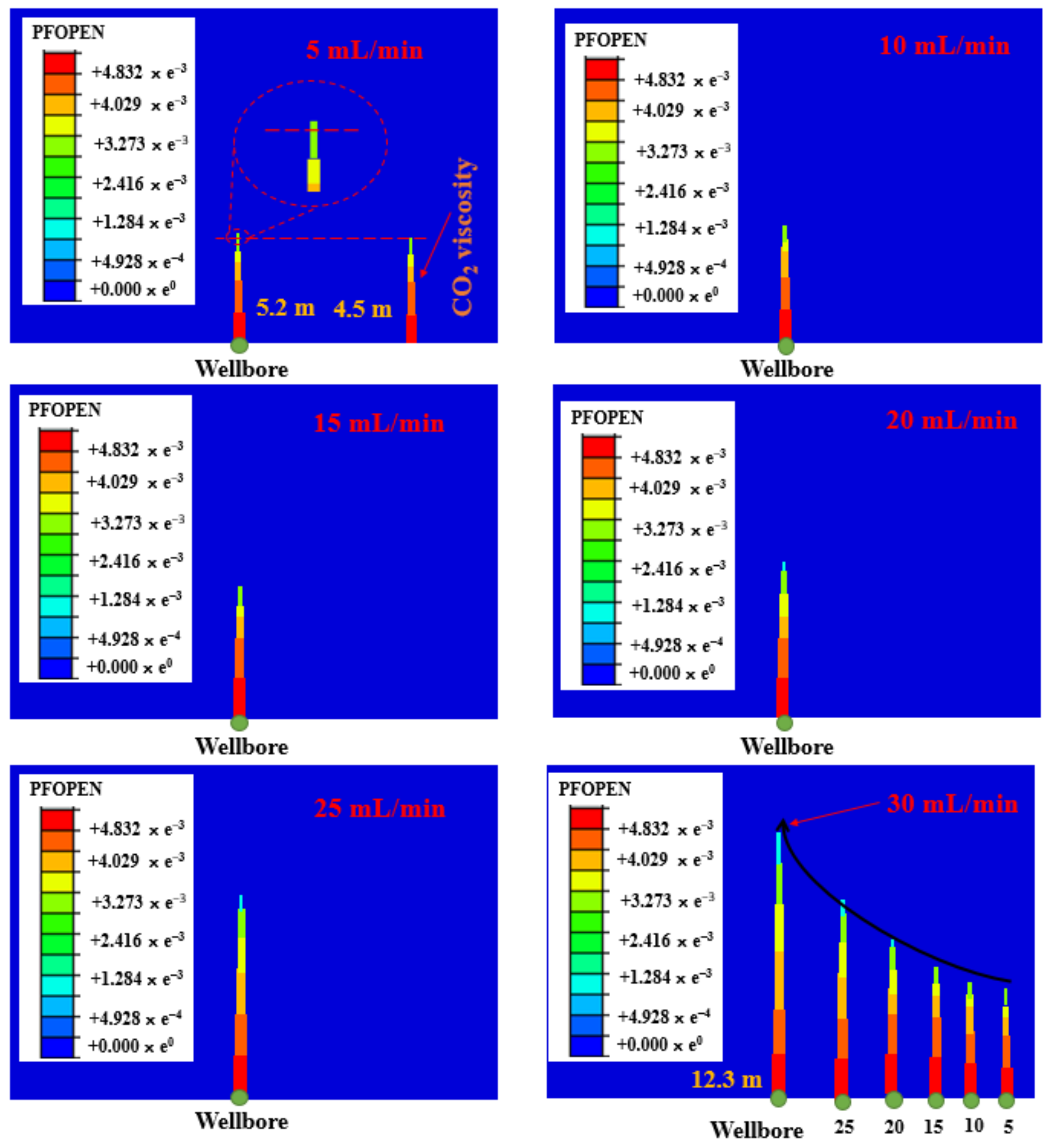
Equation (8) demonstrated the relationship between fluid injection rate, fluid viscosity, fluid pressure, and crack propagation. This indicated that the rate of crack propagation can be influenced by the injection rate. It can be seen from Figure 9 that an obvious positive proportional function was observed between fluid velocity and crack width, and this changing trend is analogous to the influence of CO2 viscosity on the crack propagation. Nevertheless, the influence of injection velocity on fracture expansion is considerably less than that of the viscosity of CO2 fracturing fluid, which is a principal reason why petroleum experts are currently engaged in the investigation of CO2 thickeners. The length and width of reservoir fractures increased in proportion to the injection rate of increased fracturing fluid. A crack width of 6.3 × 10⁻³ m and a crack length of 5.2 m were observed when the injection rate of 5 mL/min was imposed on the CO2 fracturing fluid. The restricted crack expansion resulting from an injection rate of 5 mL/min is attributed to the inadequate generation of CO2 pressure at this rate; alternatively, the low injection rate is unable to meet the minimum initiation pressure requirements for shale fractures [41,42]. The CO2 pressure that cannot rapidly reach the minimum requisite pressure to prompt a fracture at the tip of the crack results in a markedly reduced crack length. In addition, the insufficient filtration and seepage resulting from the low injection rate diminish the pressure distribution of Supercritical CO2 in the normal direction of the fracture, thereby causing a reduction in fracture width [43]. The continuous increase in injection rate will facilitate the extension and expansion of shale fractures, particularly in terms of their tangential length and normal width. However, an injection rate of 10 mL/min has only resulted in a slight increase in these parameters, with the tangential length and normal width of shale fractures reaching 9.3 × 10⁻³ m and 5.8 m, respectively. The injection rate of 10 mL/min can rapidly elevate the fracture pressure of Supercritical CO2 to the minimum requisite for reservoir fracture initiation, and the tangential expansion frequency (length) of cracks will also continue to accelerate.
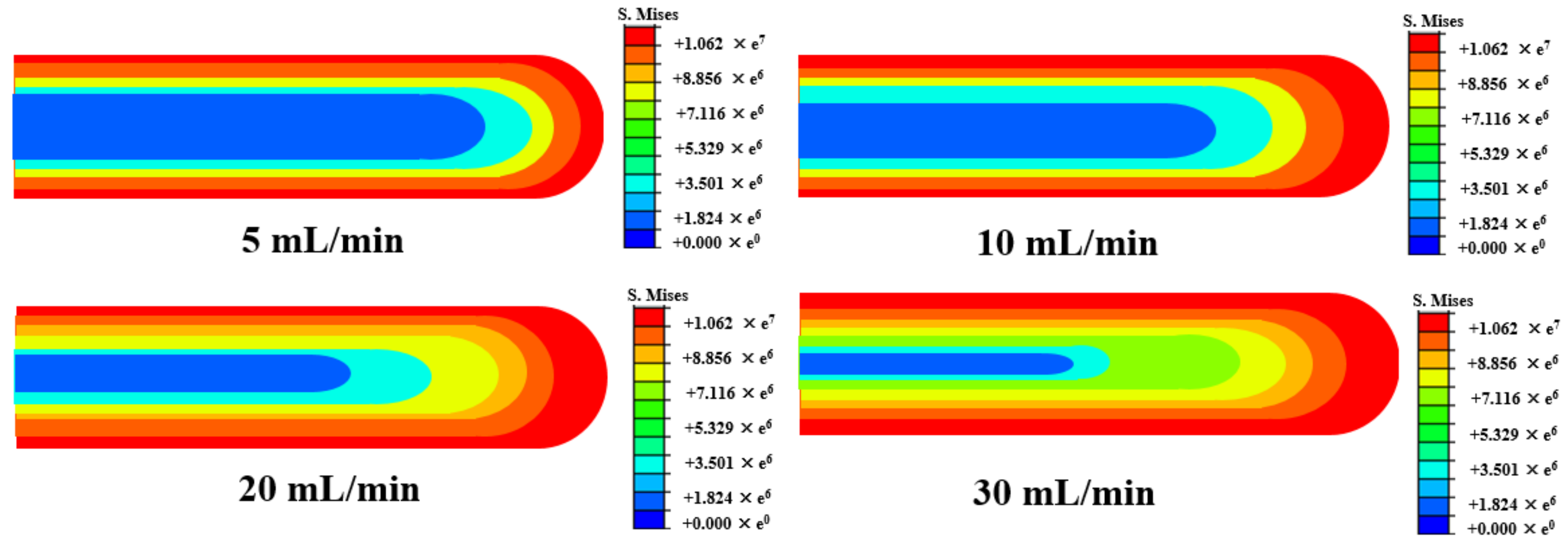
The normal width of shale fractures also simultaneously improved, and two factors can be identified as contributing to the normal propagation of this shale crack. ① The increase in CO2 pressure within the crack is a significant contributing factor to the observed increase in the normal width of the crack. As illustrated by Equation (8), a double increase in fluid pressure (▽p) and fracture width was attributed to an increased injection rate q. The application of Supercritical CO2 to the crack tip with a specific liquid pressure will result in the material being compressed in both directions perpendicular to the shale crack (Figure 10). Moreover, the CO2 pressure exerted in the normal direction of the fracture will exhibited a positive exponential change as the injection rate increases [44]. ② The gradual increase in CO2 filtration also resulted in the expansion of small fractures on both sides of the reservoir cracks. The small gaps on either side of the reservoir fractures are consistently filled and enlarged by Supercritical CO2 due to the high injection rate and CO2 pressure. Although the filtration and seepage of Supercritical CO2 can initially result in a decrease in CO2 pressure within the main fractures of a shale reservoir, the rapid inflow of Supercritical CO2 can rapidly offset the pressure, leading to an increase in CO2 pressure within the main fractures [45].
Figure 9 also indicates that the fracture propagation of shale reservoirs is significantly enhanced with an injection rate exceeding 20 mL/min. At an injection rate of 30 mL/min, the fracture width and length of the shale reservoir can reach 23 × 10−3 m and 12.3 m, respectively. Furthermore, the slope of the reservoir fracture length curve generated by the injection rate is markedly higher than the normal expansion (width), indicating that the filtration of Supercritical CO2 caused by the injection rate has a relatively weak effect on the fracture width. The injection rate increase resulted in a notable exponential increase in the fracture propagation parameter. However, exceedingly elevated injection rates can precipitate conspicuous defects, including fracturing fluid waste and reservoir damage. Therefore, it is crucial to circumvent the disadvantages associated with an excessive injection rate in on-site construction in oil fields, which necessitates a maximum fracture expansion.

3.4. Effects of Crack Azimuth on the Reservoir Fractures

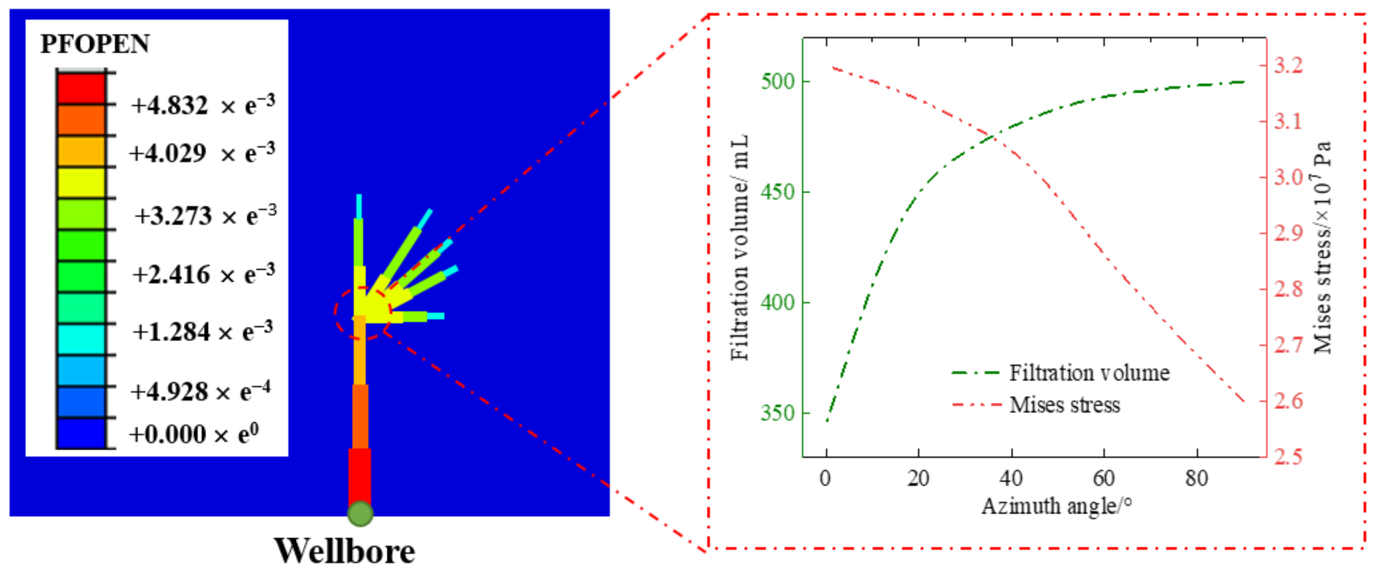
Reservoir fractures can take on different forms, including single fractures, cross fractures, and transverse fractures. The analysis of the azimuth angle of cross fractures is of practical significance for understanding the processes of crack initiation and propagation. Figure 11 illustrates the effects of different azimuth angle on the crack width and crack length. It demonstrates a gradual decreasing decline in crack propagation parameters as the azimuth angles of cross cracks increase in a regular manner. It should be noted that an azimuth angle of 0° is considered a single crack, which is not classified as a cross crack within the scope of this research. An azimuth angle of 0° (unidirectional crack) has the potential to result in the crack width and length reaching 1.83 × 10⁻² m and 12.5 m, respectively. The inverse downward trend results in a greater crack propagation capacity at an azimuth angle of 30°. The observed reduction in the magnitude of the downward trend indicates a transition from unidirectional to cross cracks in the crack propagation, with a crack width of 1.669 × 10⁻² m and a crack length of 11.5 m. The discrepancy in fracture propagation resulting from the conversion of shale fractures can be attributed to the resistance of Supercritical CO2 at the fracture corners. When Supercritical CO2 encounters a rock wall obstruction in the form of corner cracks during the flow process, a significant reduction in both the CO2 flow rate and CO2 pressure is observed. Concurrently, the continued elevation of the crack steering angle from 30° to 45° will result in a reduction in the observed crack width and length, and the crack parameters are reduced to 1.427 × 10⁻² m and 10.1 m, respectively. However, a crack orientation exceeding 60° will markedly diminish the rate of crack propagation. A crack orientation of 60° will reduce the crack width and length to 1.287 × 10⁻² m and 8.5 m, respectively. Extreme crack corner resistance was considered an important factor in reducing crack propagation; the Supercritical CO2 will first collide with the crack in the flow direction when Supercritical CO2 in the crack flows to the corner position with a steering angle of 60°. It can be observed that approximately 50% (cos 60°) of the Supercritical CO2 will continue to expand the shale fractures in the direction of the steering angle. However, a steering angle of 45° results in 70% (cos 45°) of the steering flow being used to continue fracturing shale fractures. The reduction in the flow rate of Supercritical CO2 directly results in a decrease in crack expansion speed and expansion capacity. Furthermore, the steering angle of 90° formed crack growth parameters of 0.813 × 10⁻² m and 6.2 m. The extremely low CO2 diversion volume (cos 90° = 0) is a significant contributing factor to the reduction in crack expansion.
In addition, the inverse relationship between azimuth angle and fracture width may also be attributed to filtration and seepage in shale reservoirs (Figure 12). A slight filtration and seepage were observed for the Supercritical CO2 in unidirectional fractures due to the minimal normal flow [46], and the frictional resistance of Supercritical CO2 in shale fractures is significantly lower than that in cross fractures. However, crossing cracks with a slight azimuth angle will permit the Supercritical CO2 within the cracks to flow to the corners and collide with the crack walls. Although the Supercritical CO2 within the fractures increases the frictional resistance, a considerable quantity of CO2 will also rapidly enter the shale through the fracture wall under the influence of the high-pressure liquid jet. High frictional resistance reduces the pressure at the tip of shale fractures, thereby preventing the tip pressure from quickly surpassing the minimum fracture initiation pressure of the reservoir. Additionally, the filtration results in a reduction in the normal pressure of Supercritical CO2 on the cracks, consequently leading to a narrowing of the cracks. Thus, the azimuth angle of cross fractures is not conducive to fracture initiation and propagation, and it strongly promotes the seepage of Supercritical CO2 fracturing fluid in shale fractures [47].

3.5. Effects of Reservoir Condition on the Reservoir Fractures

Reservoir temperature is not only an important parameter affecting the performance of the reservoir fluid, but also significantly impacts crack propagation. Figure 13 illustrates that a rising fracture width and fracture length are demonstrated with increasing reservoir temperature, while lower reservoir temperatures construct relatively finer and shorter reservoir fractures [48]. A crack width of 7.9 × 10⁻³ m and a crack length of 6.1 m are exhibited for the 80 °C reservoir temperature, without changing other conditions. The extremely limited fracture propagation capacity is insufficient to meet the recovery requirements of shale reservoirs. In addition, smaller shale fractures formed at low temperatures also result in a reduction in the reservoir sweep coefficient, preventing a significant quantity of supercritical CO2 fracturing fluid from covering a wider reservoir due to the limitations of the fractures [49]. Subsequently, elevated reservoir temperature results in the expansion of fissures within the shale reservoir to varying extents. It has been demonstrated that fractures formed at low temperatures have poor propagation capabilities [50]. However, higher reservoir temperatures in shale reservoirs alter the fracture propagation parameters, resulting in faster fracture propagation. A reservoir temperature of 100 °C will increase the crack width to 8.0 × 10⁻³ m, indicating that an increase in reservoir temperature can facilitate the propagation of fractures in shale reservoirs. Additionally, a gradually increasing crack length of 6.25 m is observed with an increase in the reservoir temperature to 100 °C. A slow-growing fracture propagation parameter indicates low fracturing efficiency at low temperatures. However, a reservoir temperature of 120 °C will significantly enhance fracture propagation in shale reservoirs and alter the physical properties of Supercritical CO2. As the reservoir temperature increases from 100 °C to 120 °C, the width of the reservoir fracture increases by 0.3 × 10⁻³ m (to 8.3 × 10⁻³ m), and the fracture length reaches 6.5 m. The rapidly increasing fracture propagation parameter indicates the significant impact of high reservoir temperature on shale reservoir stimulation, which may be related to the fluid form and filtration of Supercritical CO2 in shale fractures. Moreover, the reservoir temperature of 160 °C results in the reservoir fracture expanding to a width of 10.1 × 10⁻³ m and a fracture length of 9.1 m. Although the temperature is not conducive to the sand-carrying performance and apparent viscosity of Supercritical CO2, the rising fracture parameters indicate that the high reservoir temperature promotes fracture expansion.
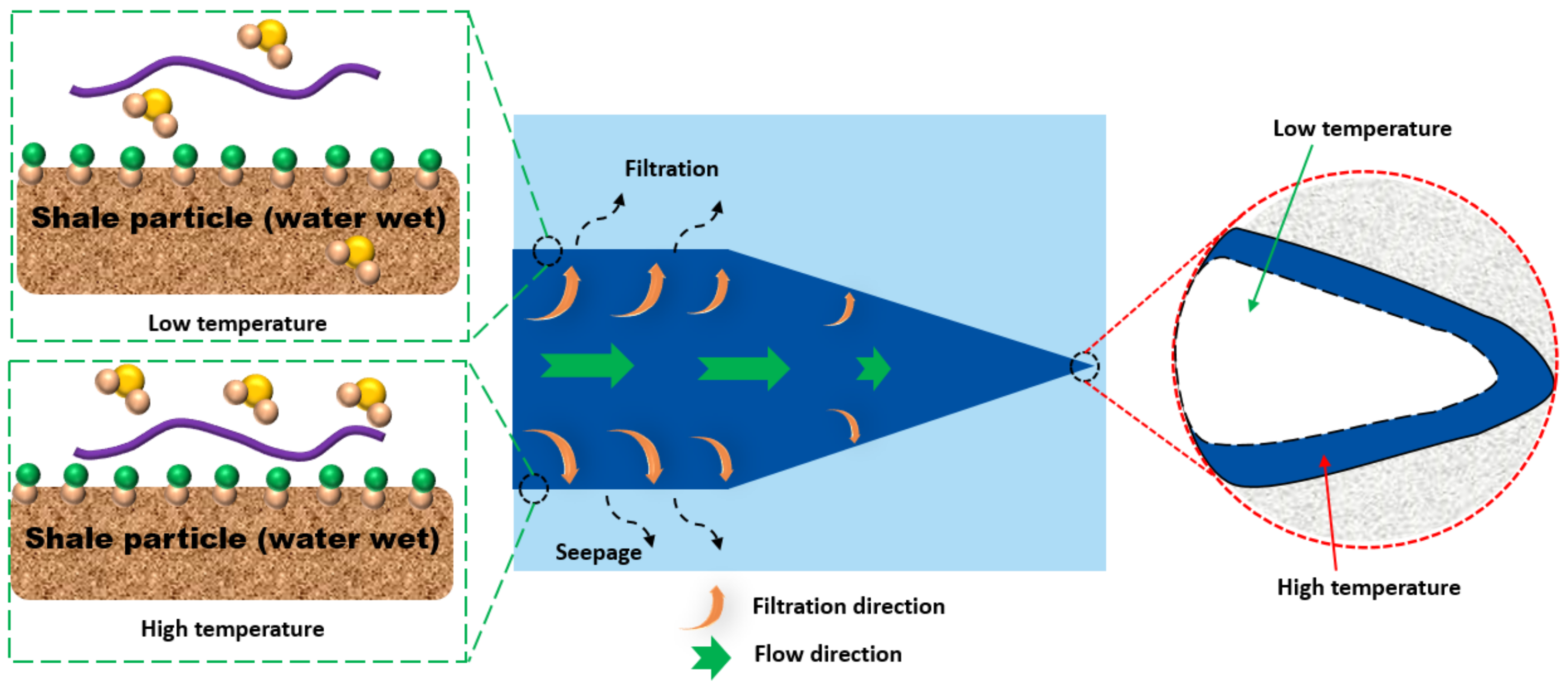
The influence of reservoir temperature on the expansion behavior of Supercritical CO2 in shale reservoir fractures can be attributed to two main factors (Figure 14): ①: Supercritical CO2 filtration. Previous studies have shown that reservoir temperature reduces the apparent viscosity of Supercritical CO2, and the microscopic chemical bonds in Supercritical CO2 fracturing fluid continue to lengthen or break due to the increase in reservoir temperature [51]. At low temperatures, the movement of molecules is relatively slow, and the microscopic grid formed by numerous fracturing fluid molecules is interconnected by chemical bonds, preventing separation. The CO2 thickener cannot adhere to the shale surface due to the obstruction of chemical bonds, resulting in a significant amount of Supercritical CO2 seeping into the shale cracks [52]. However, an increase in reservoir temperature can elevate the activity of a multitude of fracturing fluid molecules, potentially leading to the disruption of intermolecular chemical bonds. The CO2 thickener, initially connected by chemical bonds to form a grid, was found to have broken and moved in the fracturing fluid. Additionally, some thickener molecules were observed adhering to the surface of the cracks. The thickening agent molecules attached to the surface of the crack impede a considerable quantity of Supercritical CO2 from infiltrating into the shale. This not only effectively reduces CO2 filtration, but also significantly increases the CO2 pressure inside the crack. ②: The adsorption of thickener on the surface of shale fractures impedes the normal seepage of Supercritical CO2 fracturing fluid, thereby increasing the pressure of Supercritical CO2 within the fractures. According to the Arrhenius equation, an increase in reservoir temperature results in enhanced activity of chemical molecules. A substantial number of molecules are persistently repelled by the elevated temperature, which directly resulted in the separation of chemical molecules that were originally confined by the microscopic grid. Furthermore, the free fracturing fluid molecules will persist in flowing to the fracture tip due to the external force, thereby maintaining an elevated pressure at the shale fracture tip [51]. Consequently, although an increase in reservoir temperature can reduce the apparent viscosity of Supercritical CO2 fracturing fluid, the fracture propagation capacity has increased significantly [52,53].
A contrasting trend is evident in the effects of reservoir pressure and reservoir temperature on shale fractures, with a reduction in fracture propagation parameters occurring as reservoir pressure rises. Nevertheless, the capacity of reservoir pressure to expand shale fractures is markedly inferior to that of reservoir temperature. Consequently, a reduction in the length of the fracture is observed under higher reservoir pressure. The prevention of fracture expansion is significantly influenced by the pressure exerted by a large reservoir. This pressure is primarily the result of the difference between the Supercritical CO2 pressure and the reservoir pressure. It can be demonstrated that the fracturing of the shale reservoir and the initiation of fractures within it can only occur when the Supercritical CO2 pressure within the fracture is greater than the reservoir pressure. However, the increase in reservoir pressure will merely seal the low-pressure Supercritical CO2 within the fractures of the shale. This results in an extremely weak fracture expansion parameter. Moreover, the increase in reservoir pressure will impede the capacity of Supercritical CO2 to breach the fracture initiation pressure, thereby reducing the fracture propagation potential. Consequently, the extremely deep and high-pressure shale reservoirs present a significant challenge to Supercritical CO2 fracturing and fracture expansion. This is also the current direction in which Supercritical CO2 fracturing fluid is used to expand shale fractures.

4. Conclusions

This investigation constructed an extended finite element model suitable for oil field sites based on the physical characteristics of shale reservoirs and the physical and chemical characteristics of Supercritical CO2 fracturing fluid. In addition, the cohesive element damage criterion and the crack initiation criterion are employed to delineate the fundamental regulations pertaining to the inception and fracturing of shale reservoirs in Supercritical CO2. The use of Supercritical CO2 fracturing fluid presents a fundamentally different approach to that of water-based fracturing. Despite this, the filtration and seepage of the fluid continue to present significant challenges to the expansion of shale fractures. Even relatively minor seepage can result in a notable increase in fracture width. The gradual increase in reservoir temperature can increase molecular activity, which in turn facilitates the expansion of shale fractures. However, an augmentation in reservoir pressure will result in a reduction in the capacity of shale fractures to propagate, which may be limited by the gradual ascent in peripheral pressure. Although an increase in the elastic modulus of rock may facilitate fracture length, a reduced fracture width and the occurrence of severe sand plugging of fractures also present obstacles to shale mining. Furthermore, breaking through shale reservoir pressure remains the most fundamental reason for fracture propagation, and it is evident that the effective augmentation of the CO2 pressure within the fracture, or the reduction in the reservoir fracture-confining pressure, represents a pivotal approach to the expansion of shale fractures.

Author Contributions

Conceptualization, L.W. (Li Wang), A.Z. and W.L.; methodology, T.S. and W.W.; validation, L.W. (Lai Wei); formal analysis, Z.C. and Q.L. All authors have read and agreed to the published version of the manuscript.

Funding

This research sponsored by the Key scientific research projects of Exploration and Development Research Institute Sinopec Jianghan Oilfield Company «Evaluation and Technical Countermeasures for Shale Oil Development in Lianggaoshan Formation of Fuxing Region» (num: JKK462300).

Informed Consent Statement

Informed consent was obtained from all subjects involved in the study.

Data Availability Statement

Data are unavailable due to privacy or ethical restrictions.

Conflicts of Interest

Authors Li Wang, Aiwei Zheng, Wentao Lu, Tong Shen, Weixi Wang, Lai Wei and Zhen Chang were employed by the Sinopec Jianghan Oilfield Company. The remaining authors declare that the research was conducted in the absence of any commercial or financial relationships that could be construed as a potential conflict of interest.

References

  1. Liu, Y.; Tang, Y.; Chang, Q.; Ma, C.; He, S.; Yuan, L. Development of a novel heat- and shear-resistant nano-silica gelling agent. Nanotechnol. Rev. 2022, 11, 2786–2799. [Google Scholar] [CrossRef]
  2. Lv, Q.; Li, Z.; Li, B.; Zhang, C.; Shi, D.; Zheng, C.; Zhou, T. Experimental study on the dynamic filtration control performance of N2/liquid CO2 foam in porous media. Fuel 2017, 202, 435–445. [Google Scholar] [CrossRef]
  3. Chuang, M.C.; Ma, H.W. Energy security and improvements in the function of diversity indices—Taiwan energy supply structure case study. Renew. Sustain. Energy Rev. 2013, 24, 9–20. [Google Scholar] [CrossRef]
  4. Emblemsvåg, J. Wind energy is not sustainable when balanced by fossil energy. Appl. Energy 2022, 305, 117748. [Google Scholar] [CrossRef]
  5. Willow, A.J.; Zak, R.; Vilaplana, D.; Sheeley, D. The contested landscape of unconventional energy development: A report from Ohio’s shale gas country. J. Environ. Stud. Sci. 2014, 4, 56–64. [Google Scholar] [CrossRef]
  6. Fleming, D.A.; Measham, T.G. Local economic impacts of an unconventional energy boom: The coal seam gas industry in Australia. Aust. J. Agric. Resour. Econ. 2015, 59, 78–94. [Google Scholar] [CrossRef]
  7. Bijay, K.C.; Ghazanfari, E. Geothermal reservoir stimulation through hydro-shearing: An experimental study under conditions close to enhanced geothermal systems. Geothermics 2021, 96, 102200. [Google Scholar]
  8. Sahu, Q.; Fahs, M.; Hoteit, H. Optimization and uncertainty quantification method for reservoir stimulation through carbonate acidizing. ACS Omega 2022, 8, 539–554. [Google Scholar] [CrossRef] [PubMed]
  9. Li, N.; Xie, H.; Hu, J.; Li, C. A critical review of the experimental and theoretical research on cyclic hydraulic fracturing for geothermal reservoir stimulation. Geomech. Geophys. Geo-Energy Geo-Resour. 2022, 8, 7. [Google Scholar] [CrossRef]
  10. Liew, M.S.; Danyaro, K.U.; Zawawi, N.A.W.A. A comprehensive guide to different fracturing technologies: A review. Energies 2020, 13, 3326. [Google Scholar] [CrossRef]
  11. Huang, Q.; Liu, S.; Wang, G.; Cheng, W. Evaluating the changes of sorption and diffusion behaviors of Illinois coal with various water-based fracturing fluid treatments. Fuel 2021, 283, 118884. [Google Scholar] [CrossRef]
  12. Wang, J.; Elsworth, D.; Wu, Y.; Liu, J.; Zhu, W.; Liu, Y. The influence of fracturing fluids on fracturing processes: A comparison between water, oil and SC-CO2. Rock Mech. Rock Eng. 2018, 51, 299–313. [Google Scholar] [CrossRef]
  13. Zhang, C.P.; Ranjith, P.G.; Perera, M.S.A.; Li, X.; Zhao, J. Simulation of flow behaviour through fractured unconventional gas reservoirs considering the formation damage caused by water-based fracturing fluids. J. Nat. Gas Sci. Eng. 2018, 57, 100–121. [Google Scholar] [CrossRef]
  14. Papavasileiou, K.D.; Michalis, V.K.; Peristeras, L.D.; Vasileiadis, M.; Striolo, A.; Economou, I.G. Molecular dynamics simulation of water-based fracturing fluids in kaolinite slit pores. J. Phys. Chem. C 2018, 122, 17170–17183. [Google Scholar] [CrossRef]
  15. Li, S.; Zhang, S.; Ma, X.; Zou, Y.; Li, N.; Chen, M.; Cao, T.; Bo, Z. Hydraulic fractures induced by water-/carbon dioxide-based fluids in tight sandstones. Rock Mech. Rock Eng. 2019, 52, 3323–3340. [Google Scholar] [CrossRef]
  16. Li, Q.; Wang, F.; Wang, Y.; Forson, K.; Cao, L.; Zhang, C.; Chen, J. Experimental investigation on the high-pressure sand suspension and adsorption capacity of guar gum fracturing fluid in low-permeability shale reservoirs: Factor analysis and mechanism disclosure. Environ. Sci. Pollut. Res. 2022, 29, 53050–53062. [Google Scholar] [CrossRef]
  17. Carmon, N.; Shamir, U.; Meiron-Pistiner, S. Water-sensitive urban planning: Protecting groundwater. J. Environ. Plan. Manag. 1997, 40, 413–434. [Google Scholar] [CrossRef]
  18. Li, Q.; Liu, J.; Wang, S.; Guo, Y.; Han, X.; Li, Q.; Cheng, Y.; Dong, Z.; Li, X.; Zhang, X. Numerical insights into factors affecting collapse behavior of horizontal wellbore in clayey silt hydrate-bearing sediments and the accompanying control stratege. Ocean Eng. 2024, 297, 117029. [Google Scholar] [CrossRef]
  19. Li, Q.; Wang, Y.; Li, Q.; Wang, F.; Bemardo, J.; Zhang, Y.; Bai, B.; Liu, F. Performance Improvement of Thickened Liquid CO2 by Introducing a Philic-CO2 Silicone Polymer. In Proceedings of the SPE Asia Pacific Oil and Gas Conference and Exhibition, Bali, Indonesia, 29–31 October 2019; SPE: Bali, Indonesia, 2020. [Google Scholar] [CrossRef]
  20. Li, Q.; Han, Y.; Liu, X.; Ansari, U.; Cheng, Y.; Yan, C. Hydrate as a by-product in CO2 leakage during the long-term sub-seabed sequestration and its role in preventing further leakage. Environ. Sci. Pollut. Res. 2022, 29, 77737–77754. [Google Scholar] [CrossRef] [PubMed]
  21. Zhao, X.; Liao, X. Evaluation method of CO2 sequestration and enhanced oil recovery in an oil reservoir, as applied to the Changqing Oilfields, China. Energy Fuels 2012, 26, 5350–5354. [Google Scholar] [CrossRef]
  22. Song, X.; Wang, F.; Ma, D.; Gao, M.; Zhang, Y. Progress and prospect of carbon dioxide capture, utilization and storage in CNPC oilfields. Pet. Explor. Dev. 2023, 50, 229–244. [Google Scholar] [CrossRef]
  23. Li, Q.; Wang, Y.; Wang, F.; Li, Q.; Kobina, F.; Bai, H.; Yuan, L. Effect of a modified silicone as a thickener on rheology of liquid CO2 and its fracturing capacity. Polymers 2019, 11, 540. [Google Scholar] [CrossRef] [PubMed]
  24. Doherty, M.D.; Lee, J.J.; Dhuwe, A.; O’Brien, M.J.; Perry, R.J.; Beckman, E.J.; Enick, R.M. Small molecule cyclic amide and urea based thickeners for organic and sc-CO2/organic solutions. Energy Fuels 2016, 30, 5601–5610. [Google Scholar] [CrossRef]
  25. Tadepalli, K.M.; Chakrabarty, S.; Patil, P.; Kumar, R. Design of CO2 Thickeners and Role of Aromatic Rings in Enhanced Oil Recovery Using Molecular Dynamics. Langmuir 2023, 39, 989–996. [Google Scholar] [CrossRef]
  26. Wang, K.; Pan, H.; Zhang, T. Experimental study of prefabricated crack propagation in coal briquettes under the action of a CO2 gas explosion. ACS Omega 2021, 6, 24462–24472. [Google Scholar] [CrossRef]
  27. Yan, H.; Zhang, J.; Zhou, N.; Wang, Y. Quantitative characterization of crack propagation behavior under the action of stage-by-stage fracturing induced by SC-CO2 fluid. Eng. Fract. Mech. 2021, 256, 107984. [Google Scholar] [CrossRef]
  28. Pouya, A.; Yazdi, P.B. A damage-plasticity model for cohesive fractures. Int. J. Rock Mech. Min. Sci. 2015, 73, 194–202. [Google Scholar] [CrossRef]
  29. Van Eekelen, H.A.M. Isotropic yield surfaces in three dimensions for use in soil mechanics. Int. J. Numer. Anal. Methods Geomech. 1980, 4, 89–101. [Google Scholar] [CrossRef]
  30. Gillemot, L.F. Criterion of crack initiation and spreading. Eng. Fract. Mech. 1976, 8, 239–253. [Google Scholar] [CrossRef]
  31. Gonçalves da Silva, B.; Einstein, H.H. Modeling of crack initiation, propagation and coalescence in rocks. Int. J. Fract. 2013, 182, 167–186. [Google Scholar] [CrossRef]
  32. Moaveni, B.; Conte, J.P.; Hemez, F.M. Uncertainty and sensitivity analysis of damage identification results obtained using finite element model updating. Comput. Aided Civ. Infrastruct. Eng. 2009, 24, 320–334. [Google Scholar] [CrossRef]
  33. Klatte, D. On a Frank-Wolfe type theorem in cubic optimization. Optimization 2019, 68, 539–547. [Google Scholar] [CrossRef]
  34. Hou, L.; Zhang, S.; Elsworth, D.; Liu, H.; Sun, B.; Geng, X. Review of fundamental studies of CO2 fracturing: Fracture propagation, propping and permeating. J. Pet. Sci. Eng. 2021, 205, 108823. [Google Scholar] [CrossRef]
  35. Cong, Z.; Li, Y.; Pan, Y.; Liu, B.; Shi, Y.; Wei, J.; Li, W. Study on CO2 foam fracturing model and fracture propagation simulation. Energy 2022, 238, 121778. [Google Scholar] [CrossRef]
  36. Zhang, Q.; Ma, D.; Liu, J.; Wang, J.; Li, X.; Zhou, Z. Numerical simulations of fracture propagation in jointed shale reservoirs under CO2 fracturing. Geofluids 2019, 2019, 2624716. [Google Scholar] [CrossRef]
  37. Vilarrasa, V.; Laloui, L. Potential fracture propagation into the caprock induced by cold CO2 injection in normal faulting stress regimes. Geomech. Energy Environ. 2015, 2, 22–31. [Google Scholar] [CrossRef]
  38. Li, Q.; Wang, Y.; Wang, F.; Ning, X.; Chuanbao, Z.; Zhang, J.; Zhang, C. Factor analysis and mechanism disclosure of supercritical CO2 filtration behavior in tight shale reservoirs. Environ. Sci. Pollut. Res. 2022, 29, 17682–17694. [Google Scholar] [CrossRef] [PubMed]
  39. Zhang, Y.; Zhang, Z.; Sarmadivaleh, M.; Lebedev, M.; Barifcani, A.; Yu, H.; Iglauer, S. Micro-scale fracturing mechanisms in coal induced by adsorption of supercritical CO2. Int. J. Coal Geol. 2017, 175, 40–50. [Google Scholar] [CrossRef]
  40. Berstad, T.; Dørum, C.; Jakobsen, J.P.; Kragset, S.; Li, H.; Lund, H.; Østbya, E. CO2 pipeline integrity: A new evaluation methodology. Energy Procedia 2011, 4, 3000–3007. [Google Scholar] [CrossRef]
  41. Zhou, J.; Zhang, L.; Pan, Z.; Han, Z. Numerical investigation of fluid-driven near-borehole fracture propagation in laminated reservoir rock using PFC2D. J. Nat. Gas Sci. Eng. 2016, 36, 719–733. [Google Scholar] [CrossRef]
  42. Zhang, B.; Li, X.; Zhang, Z.; Wu, Y.; Wu, Y.; Wang, Y. Numerical investigation of influence of in-situ stress ratio, injection rate and fluid viscosity on hydraulic fracture propagation using a distinct element approach. Energies 2016, 9, 140. [Google Scholar] [CrossRef]
  43. Kalantariasl, A.; Farajzadeh, R.; You, Z.; Bedrikovetsky, P. Nonuniform external filter cake in long injection wells. Ind. Eng. Chem. Res. 2015, 54, 3051–3061. [Google Scholar] [CrossRef]
  44. Jiang, Y.; Qin, C.; Kang, Z.; Zhou, J.; Li, Y.; Liu, H.; Song, X. Experimental study of supercritical CO2 fracturing on initiation pressure and fracture propagation in shale under different triaxial stress conditions. J. Nat. Gas Sci. Eng. 2018, 55, 382–394. [Google Scholar] [CrossRef]
  45. Oldenburg, C.M. Migration Mechanisms and Potential Impacts of CO2 Leakage and Seepage. 2006. Available online: https://escholarship.org/content/qt015944r2/qt015944r2.pdf (accessed on 1 July 2024).
  46. Yang, K.; Wang, L.; Ge, J.; He, J.; Sun, T.; Wang, X.; Zhao, Y. Impact of formation dip angle and wellbore azimuth on fracture propagation for shale reservoir. Processes 2023, 11, 2419. [Google Scholar] [CrossRef]
  47. Eshiet, K.I.I.; Sheng, Y. The role of rock joint frictional strength in the containment of fracture propagation. Acta Geotech. 2017, 12, 897–920. [Google Scholar] [CrossRef]
  48. Liu, W.; Zeng, Q.; Yao, J. Numerical simulation of elasto-plastic hydraulic fracture propagation in deep reservoir coupled with temperature field. J. Pet. Sci. Eng. 2018, 171, 115–126. [Google Scholar] [CrossRef]
  49. Zhang, B.; Guo, T.; Qu, Z.; Wang, J.; Chen, M.; Liu, X. Numerical simulation of fracture propagation and production performance in a fractured geothermal reservoir using a 2D FEM-based THMD coupling model. Energy 2023, 273, 127175. [Google Scholar] [CrossRef]
  50. Zhou, D.; Zhang, G.; Prasad, M.; Wang, P. The effects of temperature on supercritical CO2 induced fracture: An experimental study. Fuel 2019, 247, 126–134. [Google Scholar] [CrossRef]
  51. Li, Q.; Wang, F.; Wang, Y.; Bai, B.; Zhang, J.; Lili, C.; Sun, Q.; Wang, Y.; Forson, K. Adsorption behavior and mechanism analysis of siloxane thickener for CO2 fracturing fluid on shallow shale soil. J. Mol. Liq. 2023, 376, 121394. [Google Scholar] [CrossRef]
  52. Li, Q.; Wang, F.; Wang, Y.; Zhang, J.; Yu, X.; Zhao, M.; Zhou, C.; Forson, K.; Shi, S.; Zhao, Y.; et al. Influence of organoboron cross-linker and reservoir characteristics on filtration and reservoir residual of guar gum fracturing fluid in low-permeability shale gas reservoirs. Environ. Sci. Pollut. Res. 2022, 29, 82975–82985. [Google Scholar] [CrossRef]
  53. Luo, X.; Wang, S.; Wang, Z.; Jing, Z.; Lv, M.; Zhai, Z.; Han, T. Experimental investigation on rheological properties and friction performance of thickened CO2 fracturing fluid. J. Pet. Sci. Eng. 2015, 133, 410–420. [Google Scholar] [CrossRef]
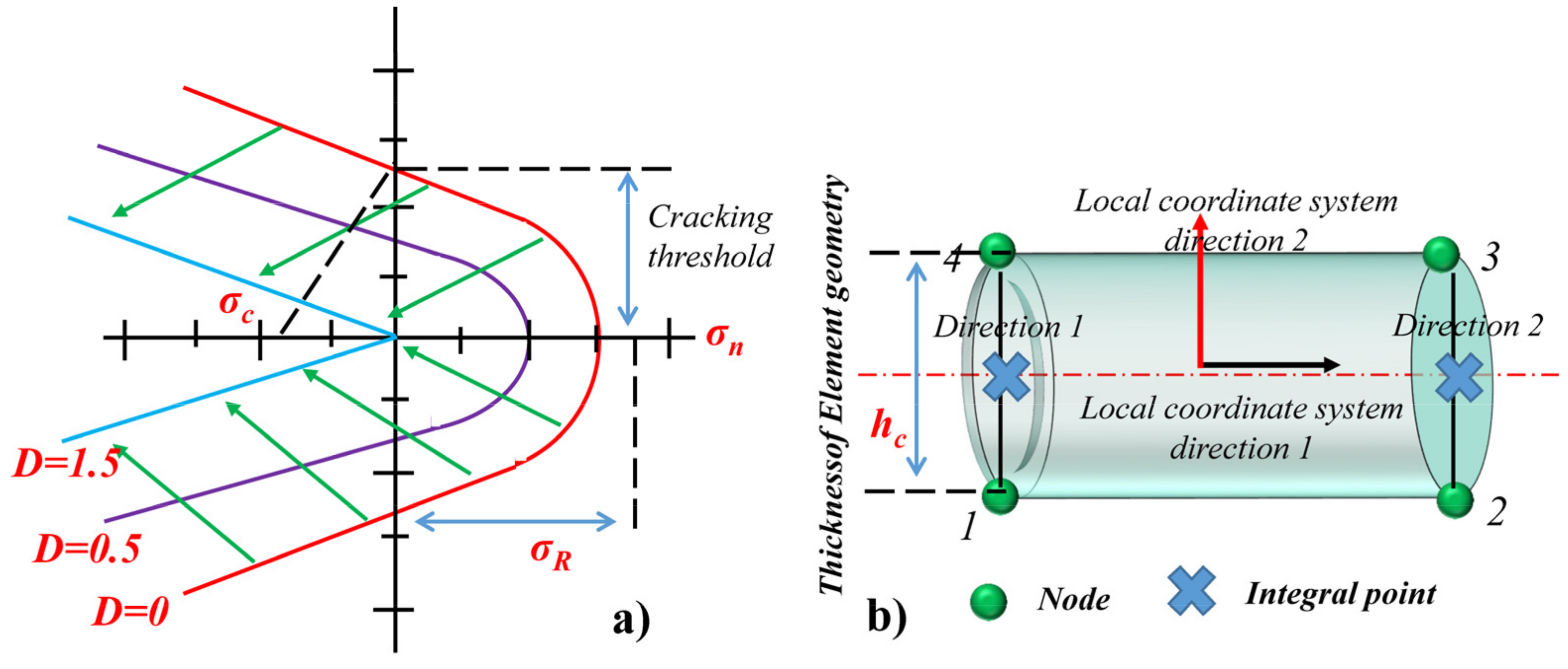
Figure 1. Cohesive unit damage and crack initiation. (a) Evolution of hyperbolic surfaces with damage plasticity criterion. (b) Diagram of 2D cohesive force unit.
Energies 17 03865 g001
Figure 2. Flow model of Supercritical CO2 fracturing fluid in fracture.
Energies 17 03865 g002
Figure 3. Supercritical CO2 fracturing model for shale reservoirs.
Energies 17 03865 g003
Figure 4. Changes in fracture morphology of shale reservoirs caused by different CO2 viscosities.
Energies 17 03865 g004
Figure 5. The influence curve of CO2 viscosity on the width and length of shale fractures.
Energies 17 03865 g005
Figure 6. Effects of tangential flow and normal flow of Supercritical CO2 on crack shape and stress.
Energies 17 03865 g006
Figure 7. Effect of apparent viscosity of different Supercritical CO2 fracturing fluids on pressure around fractures.
Energies 17 03865 g007
Figure 8. Effect of elastic modulus on shale fracture propagation.
Energies 17 03865 g008
Figure 9. Effect of fracturing fluid injection rate on shale fracture propagation.
Energies 17 03865 g009
Figure 10. Distribution of shale fracture stress under different fracturing fluid injection rates.
Energies 17 03865 g010
Figure 11. Differences in crack morphology and expansion under different azimuth angles.
Energies 17 03865 g011
Figure 12. Differences in crack filtration and Mises stress under different azimuth angles.
Energies 17 03865 g012
Figure 13. Differences in the propagation of shale fractures at different reservoir temperatures.
Energies 17 03865 g013
Figure 14. Changes in normal and tangential fractures at different reservoir temperatures.
Energies 17 03865 g014
Table 1. The characteristic parameters and the initial conditions of shale reservoirs.
ParameterValueParameterValue
Elastic Modulus, E/GPa20Poisson’s ratio, ν0.28
Minimum horizontal principal stress, σh/MPa35Maximum horizontal principal stress, σH/MPa40
Tensile strength, C/MPa4Initial pore pressure, Pip/MPa17
Initial porosity, ϕ/%7Permeability, K/m25 × 10−16
Leak-off coefficient1.2 × 10−12Total fracturing time, T/min10
Table 2. Influence of reservoir elastic modulus on shale fracture parameters.
Elastic Modulus, E/GPa20304050
Crack length/m12.312.914.516.9
Crack width/×10−2 m21.81.51.1
Disclaimer/Publisher’s Note: The statements, opinions and data contained in all publications are solely those of the individual author(s) and contributor(s) and not of MDPI and/or the editor(s). MDPI and/or the editor(s) disclaim responsibility for any injury to people or property resulting from any ideas, methods, instructions or products referred to in the content.