1. Introduction
With the continuous development and widespread application of new energy technologies, the market share of electric vehicles (EVs) is gradually increasing, showing a trend in replacing traditional fuel vehicles. However, there are still significant technological barriers in the energy-storage batteries of EVs. Energy storage batteries are large in size, and their energy density is significantly lower compared to fossil fuels, resulting in much shorter driving ranges than traditional vehicles. To achieve longer driving ranges, EVs need to be equipped with larger capacity batteries. Traditional EV-charging stations and sites typically take an average of 10 h to fully charge the battery, leading to long charging times. Additionally, these charging stations and sites have exclusivity and spatial limitations, allowing only a limited number of EVs to charge at specific times.
To address this issue, a battery-swapping mode has been proposed. The battery-swapping mode for EVs is a rapid method of replenishing electrical energy. In this mode, the battery that is running low on charge is removed from the EV, and a fully charged battery is replaced in its place. This allows the vehicle owner to drive to a battery-swapping station and complete the battery exchange in just a few minutes. This approach not only significantly reduces waiting times for vehicle owners but also maximizes the utilization of charging infrastructure at battery-swapping stations. Israel’s Better Place company conducted large-scale commercial tests of battery swapping as early as 2007 [
1]. However, due to high costs and battery-specification inconsistencies, they announced the cessation of operations in May 2013. In June 2013, Tesla introduced a 93 s battery-swapping technology [
2], but it also faced challenges related to cost-effectiveness and was eventually discontinued. The most critical technical issues for battery-swapping stations involve the balance of battery packs during the charging process and the energy management of distributed batteries.
SOC and SOH are two critical parameters in battery management, and they hold significant importance for both the performance and lifespan of the battery [
3]. Firstly, SOC represents the percentage of the battery’s current state of charge, i.e., the ratio of stored charge in the battery relative to its maximum capacity. It provides essential information for users by offering intuitive feedback about the available energy in the battery. Understanding SOC helps users schedule the use of the battery’s time and energy effectively, preventing the battery from running out of charge at crucial moments [
4]. Secondly, SOH represents the health condition of the battery, indicating its current state relative to its initial performance. Over time, batteries undergo processes like cyclic charge–discharge and natural decay, and SOH reflects the aging degree of the battery. Understanding SOH aids in predicting battery lifespan, facilitating timely maintenance or replacement to extend the battery’s usable life. The comprehensive consideration of these two parameters enables the battery-management system to intelligently monitor and control the battery’s operational status [
5]. The real-time monitoring of SOC and SOH allows the system to optimize charging and discharging strategies, preventing overcharging and discharging, thereby enhancing the battery’s safety and stability. Additionally, SOC and SOH information provides crucial guidance for the design and operation of electric vehicles and energy-storage systems, ensuring the reliability and performance of the equipment. Therefore, the integrated consideration of SOC and SOH is a key factor in ensuring the efficient and stable operation of batteries during usage, maximizing their lifespan [
6].
The fast identification of micro-health parameters for retired batteries is crucial for the following reasons: (1) Batteries may undergo physical damage, overcharging and over-discharging, etc., during usage, potentially causing changes in the microstructure of the battery. The timely identification of micro-health parameters helps assess the safety of the battery, preventing potential risks, such as battery explosions or fires due to health issues. (2) Micro-health parameters directly impact the battery’s performance. The rapid identification of these parameters allows for the assessment of performance indicators, such as capacity, charge–discharge efficiency, and cycle life, etc. This is crucial in deciding whether the battery is suitable for reuse, secondary use, or if it requires a repairing or replacement. (3) For large-scale battery applications like electric vehicles, energy-storage systems, rapidly and accurately understanding the micro-health condition of the battery helps reduce maintenance costs. Identifying problems promptly allows for appropriate maintenance measures, extending the battery’s lifespan, and maximizing its economic benefits [
7].
Inconsistent parameters such as the capacity and internal resistance of individual cells within a battery pack have negative effects on the overall capacity and lifespan of the entire battery pack [
8]. Inconsistent internal resistance can result in uneven charging and discharging currents in parallel-connected battery cells, leading to some cells reaching a fully charged or depleted state prematurely [
9]. Inconsistent capacity can lead to the over-charging or over-discharging of certain individual cells within the battery pack. Hence, to estimate the state of charge or the internal status of the battery accurately with non-destructive approaches is vital. In [
10], ultrasonic reflection waves are employed to achieve an accurate estimation of the battery’s state of charge and internal status. This is a non-destructive method that has minimal adverse effects on the battery and boasts a high precision. Research on balanced charging primarily focuses on two aspects: balanced charging topologies and control strategies [
11].
Regarding balanced charging topologies, based on whether there is energy loss in the circuit, balanced circuits can be categorized as energy-consuming (passive balance circuits) and non-energy-consuming (active balance circuits). Energy-consuming balance circuits discharge higher-capacity individual cells in the battery pack through series-connected shunt resistors. They have a simple structure and are easy to control but suffer from high energy loss, low efficiency, and heat generation, making them unsuitable for large-capacity electric vehicle power battery-pack balancing [
12]. Non-energy-consuming circuits utilize semiconductor power switches and LC passive components to construct DC-DC converters, enabling an energy transfer between batteries and achieving battery balancing [
13]. Switched-capacitor-based balance circuits are used for battery-pack balancing in [
14,
15], but they have the drawback of only being able to use voltage as the balancing variable. This leads to extended balancing times when the voltage difference between two individual cells is small, as the balancing process is related to the charging and discharging conditions of the capacitors. Buck/Boost and Cuk converter-based balance circuits are applied in [
16,
17,
18]. They are not restricted by the voltage levels of individual cells and can perform bidirectional balancing.
In terms of balanced charging control strategies, battery voltage is regarded as the indicator to detect battery inconsistencies and evaluate the effectiveness of balancing control during idle and charge/discharge phases in [
19,
20,
21]. However, it is indicated in [
22] that using the battery State of Charge (SOC) as a balancing control variable can better improve battery pack consistency and enhance energy utilization compared to voltage-based approaches. In [
23,
24], both voltage and SOC are used as balancing variables and develop corresponding models, demonstrating that, under accurate SOC estimation, SOC-based balancing yields better results than voltage-based balancing. Model Predictive Control (MPC) is employed in [
25] to balance and distribute energy within the battery pack.
Battery-management systems (BMSs) primarily encompass functions such as data monitoring, data management, charge/discharge control, State of Charge (SOC) estimation, State of Health (SOH) assessment, communication, real-time status visualization display, fault warning, and protection [
26]. A typical BMS structure proposed by the University of Toledo consists of a microcontroller (MCU) and battery balancer (EQU). The MCU is responsible for data acquisition, analysis, processing, and uploading, while the balancer handles the balancing of batteries among themselves [
27]. The Advanced Engineering Institute at Ajou University in South Korea gives more comprehensive consideration to thermal management, safety protection devices, and charge/discharge control [
28]. After years of research and development, the BMS has evolved from a simple monitoring system into a fully functional management system. However, there is still significant room for improvement and innovation in areas such as information-acquisition accuracy, communication, SOC and SOH estimation, fault diagnosis, and charging/discharging control. In [
29], a cooperative control method was introduced for a hybrid AC/DC microgrid involving photovoltaics, wind power, and batteries. This method achieves efficient and reliable charging control of batteries by renewable energy sources. In [
30], an accurate estimation of lithium-ion battery capacity is achieved using deep convolutional neural networks.
Despite the considerable research efforts and some progress made by researchers in battery balancing and energy-management technologies, there has been relatively limited research at the level of holistic system design. This paper explores a systematic design and implementation approach for a battery-energy comprehensive management platform in charging and swapping scenarios. It comprehensively designs the battery-management system (BMS) from the perspectives of hardware, balancing strategies, coordination strategies, and protection strategies, and successfully implements it. This design methodology holds significant implications for guiding the design of BMSs in the field of charging and swapping.
The detailed contributions of this study are summarized as follows:
The proposed method innovatively considers the platform’s design from a global perspective, rather than solely focusing on implementing individual functionalities. The designed system significantly reduces the occurrence of incompatibility between various hardware and control units, enhancing the overall system coordination;
The proposed method seamlessly integrates the design processes of hardware and software, achieving comprehensive and reliable control, protection, intelligent charging balance, accurate energy estimation, data uploading, and data storage;
The proposed method incorporates new emergency protection and black start-up strategies, making the designed platform even more secure.
The organization of this paper is as follows:
Section 2 provides a detailed description of the systematic design and implementation method of the proposed battery-energy comprehensive management platform.
Section 3 presents the experimental results and provides a detailed analysis. The conclusion is given in
Section 4.
2. Proposed Battery Energy Comprehensive Management Platform
The battery-energy comprehensive management platform is a visual platform for safety supervision and coordinated control based on system hardware and software design, as well as the design of key control strategies. The platform’s hardware includes power units, information acquisition units, control units, and communication units, etc. Software- and system-control strategies are closely related, with core control strategies including dynamic load charging-balance control, composite micro-source hierarchical coordination control, and emergency and protection strategies. In addition, the software also handles functions such as databases and visual interfaces. The proposed battery-energy comprehensive management platform is depicted in
Figure 1.
2.1. Hardware Design
The BMS requires the real-time monitoring of battery voltage, current, and temperature to achieve comprehensive and reliable control, protection, intelligent charging balancing, and an accurate estimation of battery capacity. Each unit should have communication capabilities and rich communication interfaces. The system should have an intuitive user interface and a simple operating process. In addition, real-time storage of key data should be implemented.
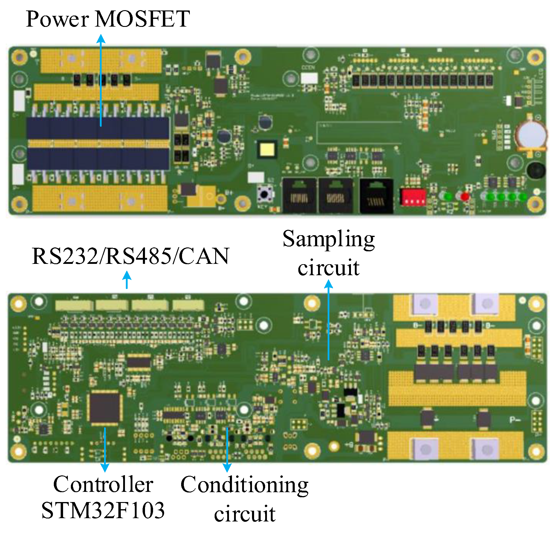
Based on the above design concept, the hardware of the BMS is divided into five units, namely the control unit, power unit, data-acquisition unit, communication unit, and host computer. The control unit uses the STM32F103ZET6 microcontroller from ST Microelectronics, and the LTC6803HG-3#TRPBF is used for the real-time monitoring of battery voltage. The current measurement is achieved using shunt resistors and operational amplifiers. The communication interfaces support RS232, RS485, and CAN protocols. The PCB layout of the BMS module is as shown in
Figure 2.
The software used for designing this PCB is called Altium Designer. After comprehensive consideration of circuit complexity and cost, it was decided to design the PCB as being double-sided. The inputs to the control system include parameters, such as the battery voltage and charge/discharge current and temperature, etc. The outputs include the reference voltage, reference current, charge/discharge limits, and start/stop commands, etc.
In terms of functional implementation, the MCU’s PWM pins control the power MOSFETs through corresponding driver circuits to achieve battery-charging and -discharging functions. The voltage-, current-, and temperature-sensing circuits of the battery sample the signals and send them to the ADC ports of the MCU. The MCU can use the built-in threshold values to control the battery’s charging-termination voltage and provide overvoltage, overcurrent, and over-temperature protections. Additionally, the voltage, current, and temperature information can be used for estimating the State of Charge (SOC) and State of Health (SOH) of the battery. To achieve the battery-data upload, battery-module parallelization, and battery limited-current charging, three communication interfaces, RS485, CAN, and RS232, have been designed. RS485 and CAN communication interfaces enable data uploading, module parallelization, and communication with the host in a standalone mode. This facilitates the online connectivity and reporting of information to the host. The built-in communication content includes the voltage, current, capacity, temperature, and heating status, which can be controlled through a host computer. The RS232 communication interface is used to realize the function of current-limiting battery charging.
2.2. Dynamic Load Charging-Balancing Control Strategy
In the context of battery-swapping stations, the distance between battery packs can be significant, and there are typically a large number of batteries within a single swapping station. If a centralized load-based or micro-source master–slave control strategy is considered, strong communication support is required. Each unit in the system needs to communicate with the central controller, imposing strict requirements on communication bandwidth. The communication net can become complex, lengthy, and prone to single-point failures. Therefore, the centralized load-based and micro-source master–slave control strategies are not suitable for battery-swapping station scenarios. Distributed droop control is well-suited for such situations. In a charge-and-swap-guarantee system, when the batteries are being charged, the micro-sources and dynamic loads in the system are connected to the DC bus in parallel through bidirectional DC-DC converters. Balancing control can be achieved through simple communication architecture among the parallel modules, allowing for plug-and-play functionality.
The equivalent circuit diagram of droop control is as shown in
Figure 3. The diagram includes
n branches of the power module.
Vo1,
Vo2, and
Von are the voltages of the power modules.
R1,
R2, and
Rn are the equivalent droop resistances of the power modules.
Rline1,
Rline2, and
Rlinen are the line resistances of each module branch.
Io1,
Io2, and
Ion are the currents of each module. According to Ohm’s law and Kirchhoff’s voltage and current laws, the voltage and current relationships between each power module conform to (1). From (1), it can be seen that the current-allocation relationship and power-allocation relationship between each module are entirely determined by the droop coefficients and line resistances of each branch.
Since the line resistances are much smaller than the chosen droop resistances, the current-allocation relationship between different power modules can be expressed as (2). From (2), it can be seen that the current-allocation relationship between each module is directly determined by the droop coefficients of each branch.
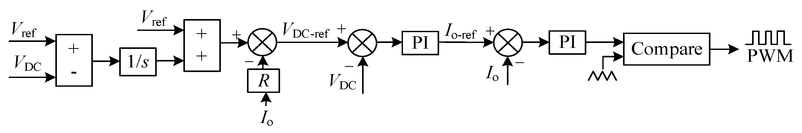
The traditional droop-control block diagram is shown in
Figure 4. In the diagram,
Vref represents the reference value of the DC bus voltage. The reference value of the DC bus voltage,
Vref, is subtracted from the droop voltage, which is the product of the branch current
Io and the droop resistance
R. This subtraction generates a new reference value for the DC bus voltage,
VDC-ref.
VDC represents the actual value of the DC bus voltage, which essentially represents the total load voltage. The voltage deviation
formed by subtracting
VDC-ref from
VDC enters the voltage loop regulator. The voltage loop regulator generates the reference current,
Io-ref. The difference
between this branch current and the actual branch current
Io, enters the current loop regulator, generating a duty cycle signal. The duty cycle,
D, is modulated and then produces the PWM signal required for the DC-DC converter after the modulation stage.
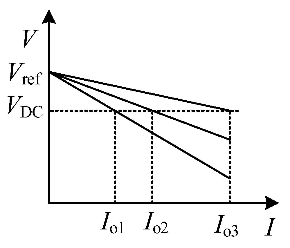
However, due to the presence of droop resistance, traditional droop control suffers from voltage deviations. The actual value of the DC bus voltage cannot fully track the desired value. The I-V characteristic curve of the droop control is as shown in
Figure 5. The bus voltage is inversely proportional to the branch current, and the slope of the droop curve represents the droop coefficient. The larger the droop coefficient, the steeper the downward slope of the curve. In traditional droop control, the deviation of the DC bus voltage is unavoidable. As long as there is current flowing through the branch, this error will occur. In
Figure 5, this error is manifested as the difference between the reference voltage at zero current and the intercept of the bus voltage at steady-state operation on the
y-axis.
To eliminate the voltage deviation in traditional droop control, a droop control based on deviation voltage secondary compensation is proposed. This control method adds a compensation loop to the reference value of the DC bus voltage compared to traditional droop control. The basic idea of this method is to add a compensation amount to the original reference value of the DC bus voltage, using a higher reference value to compensate for the deviation caused by the droop coefficient while maintaining the power distribution characteristics of traditional droop control. The block diagram of the droop control based on deviation voltage secondary compensation is as shown in
Figure 6. The error between the reference value and the actual value of the DC bus voltage is accumulated and integrated. The integrated value is added as a compensation value to the reference value of the DC bus voltage, forming a new reference value for the DC bus voltage.
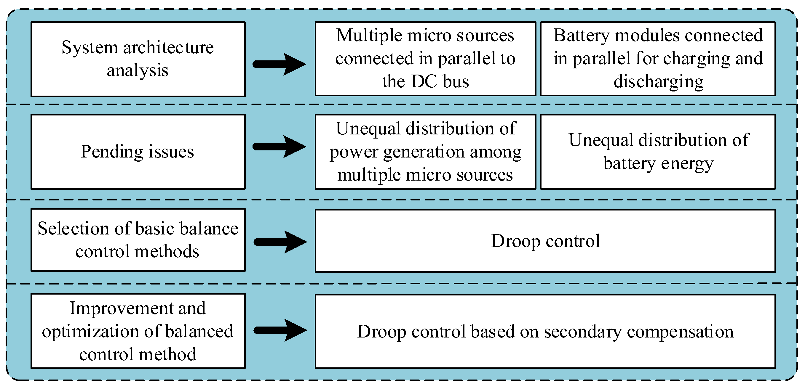
Based on the analysis of the architecture of the interchange station system, starting from the issues to be solved, the dynamic load balancing-control method is selected and optimized based on the basic control method. The technical route of the dynamic load balancing-control strategy is as shown in
Figure 7.
2.3. Composite Micro-Source Hierarchical Coordination Control Strategy
In order to achieve energy scheduling and power matching for the charge-and-swap platform, a hierarchical control strategy is adopted to design a comprehensive energy-management platform based on system constraints such as optimal energy scheduling, power-balancing matching, and economic stable operation. The detailed technical algorithm is as shown in
Figure 8.
The first layer is the control of the DC bus voltage. In a multi-source power supply system integrated in the form of a DC bus, there is no need to consider issues such as frequency, phase, and reactive power. The DC bus voltage is the only signal of source–load coordination and energy balance. This system uses the DC bus voltage as the global signal, divides the bus voltage into several intervals within its allowable fluctuation range, and uses equivalent control technology for at least one micro-source in each interval to ensure power balance in the system. Energy storage systems, photovoltaic power generation systems, and oil engines/power grids, etc. use the DC bus voltage to determine their own operating modes and select corresponding control algorithms.
The second layer is the control of the SOC of the energy-storage unit, i.e., the battery. Based on the SOC information obtained by the data-acquisition system, it is determined whether to charge or discharge the battery, and further develops fine and intelligent charging and discharging strategies for the battery. For batteries that have been fully charged, they should be removed from the system in time.
The third layer is the control of the load-power level. Batteries in the charging state are considered loads, and other types of loads, such as motors and lighting devices, are connected to the DC bus. The system should be able to adjust the power on the micro-source side according to the real-time demand for the power-level of the system. When the demand for load power is too large, and the power generated by the micro-sources is insufficient to support all the loads, the system can cut in and out loads according to priority.
2.4. System Emergency and Protection Strategy
If a certain extreme situation occurs and the energy storage is disconnected, and the system enters a complete blackout state, how to achieve a black start for the system and further improve the system’s reliability and security is a key issue that must be considered. In order to prevent such situations from happening, a black start control strategy has been developed, and its technical algorithm is as shown in
Figure 9.
The determination criteria for black start and normal operation are that the energy-storage system is online and the voltage is above a certain threshold. If the energy-storage system is offline or the voltage is below the threshold, the system enters black start mode. If the energy-storage system is online and the voltage is above the threshold, the system enters normal operation mode.
A certain capacity of photovoltaic (PV) and utility/grid power/diesel generator are selected as the black start sources for the system. The distributed monitoring unit monitors the status of the PV controller and rectifier module. If the PV controller is online, the system enters PV black start mode. If the rectifier module is online, the system enters rectifier black start mode instead. If both PV and rectifier are online, PV black start mode takes priority. The black start strategy used in this paper is as shown in
Figure 10. The distributed monitoring unit adjusts the output voltage of the black-start source slightly higher than the threshold voltage, and then closes the black-start relay to provide a small current charge to the energy-storage battery. When the voltage of the energy-storage battery exits the under-voltage disconnection state, the black-start process is completed.
3. Experimental Results and Analysis
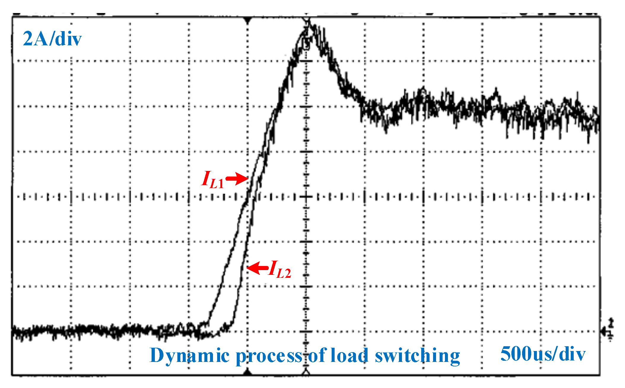
To verify the effectiveness of the dynamic load balancing charging-control strategy, two power modules were used to charge the batteries in the experiment. The experimental result of the dynamic load balancing charging with a secondary compensating droop control is as shown in
Figure 11. The charging currents of the two power branches rise from 0 A to 10 A, and the dynamic process lasts for approximately 1500 us. Both during the dynamic process and the steady-state process, the currents of the two branches show a good consistency.
To differentiate at 5 A intervals, the output voltage was tested for 10 different charging currents ranging from 0 A to 50 A. The I-V characteristic curve based on the secondary compensating droop control is as shown in
Figure 12. It can be observed from the graph that the DC bus voltage can be maintained at the reference value of 57 V under different charging currents. Therefore, the secondary compensation successfully eliminates the voltage deviation in a traditional droop control.
To validate the system’s capability for multi-source power mode-switching, experiments were conducted involving mode switches among different combinations. The objective of these experiments was to assess the adaptability and reliability of the system when facing various power-source combinations. The power-source combinations at the supply end include the following: (a) grid power, (b) diesel generator, (c) energy storage, (d) grid power + energy storage, (e) diesel generator + energy storage, (f) photovoltaic + energy storage, (g) grid power + photovoltaic + energy storage, (h) diesel generator + photovoltaic + energy storage, (i) photovoltaic + grid power, and (j) photovoltaic + diesel generator. The experimental results are shown in
Table 1, indicating successful switching between any two power-supply modes. The system demonstrates excellent capabilities for multi-source power mode-switching, swiftly transitioning between single and multiple power-source combinations as needed, ensuring the continuous and stable operation of the system. The flexibility of this multi-source power mode is expected to provide more reliable and efficient energy management solutions for power systems, under diverse working conditions. These results have positive implications for advancing renewable energy, energy-storage technologies, hybrid energy systems, and for enhancing the robustness of power systems.
Consider a logistics company that owns a large fleet of electric trucks for urban delivery. The company has implemented a battery-energy comprehensive management platform in the context of charging and swapping scenarios to enhance the operational efficiency and cost-effectiveness of their electric vehicle fleet. In this application case, the battery-energy comprehensive management platform will play the following roles: (1) Smart charging scheduling: The platform, by the real-time monitoring of the vehicles’ battery status and operational conditions, coupled with the battery-energy comprehensive management algorithm, intelligently schedules charging plans. Based on the actual usage patterns of the vehicles, the platform ensures optimal timings for battery charging, guaranteeing sufficient energy before peak periods. (2) Battery health management: The platform conducts health monitoring and analysis for each battery. Through the real-time feedback of data, such as battery temperature, current, and capacity, the platform predicts battery lifespan, avoiding overcharging and over-discharging to extend battery life, as well as reducing replacement costs. By introducing such a battery-energy comprehensive management platform, the logistics company can more effectively manage the energy consumption of electric vehicles, reduce operating costs, improving delivery efficiency, and achieving a lesser environmental impact. This case study highlights the practical application potential of the battery-energy comprehensive management platform in commercial operations within charging and swapping scenarios.


