Article

Heat and Flow Characteristics of Aerofoil-Shaped Fins on a Curved Target Surface in a Confined Channel for an Impinging Jet Array

1
Mechanical Engineering Department, Faculty of Engineering, Sakarya University, 54050 Sakarya, Türkiye
2
Department of Electricity and Energy, Vocational School of Technical Sciences at Mersin Tarsus Organized Industrial Zone, Tarsus University, 33100 Mersin, Türkiye
3
Center of Flow Simulation (CFS), Faculty of Mechanical and Process Engineering, Düsseldorf University of Applied Sciences, Münsterstr. 156, 40476 Düsseldorf, Germany
*
Author to whom correspondence should be addressed.
Energies 2024, 17(5), 1238; https://doi.org/10.3390/en17051238
Submission received: 24 January 2024 / Revised: 21 February 2024 / Accepted: 28 February 2024 / Published: 5 March 2024

Abstract

:
The main purpose of this investigation was to explore the heat transfer and flow characteristics of aero-foil-shaped fins combined with extended jet holes, specifically focusing on their feasibility in cooling turbine blades. In this study, a comprehensive investigation was carried out by applying impinging jet array cooling (IJAC) on a semi-circular curved surface, which was roughened using aerofoil-shaped fins. Numerical computations were conducted under three different Reynolds numbers (Re) ranging from 5000 to 25,000, while nozzle-to-target surface spacings (S/d) ranged from 0.5 to 8.0. Furthermore, an assessment was made of the impact of different fin arrangements, single-row (L1), double-row (L2), and triple-row (L3), on convective heat transfer. Detailed examinations were performed on area-averaged and local Nusselt (Nu) numbers, flow properties, and the thermal performance criterion (TPC) on finned and smooth target surfaces. The study’s results revealed that the use of aerofoil-shaped fins and the reduction in S/d, along with surface roughening, led to significant increases in the local and area-averaged Nu numbers compared to the conventional IJAC scheme. The most notable heat transfer enhancement was observed at S/d = 0.5 utilizing extended jets and the surface design incorporating aerofoil-shaped fins. Under these specific conditions, the maximum heat transfer enhancement reached 52.81%. Moreover, the investigation also demonstrated that the highest TPC on the finned surface was achieved when S/d = 2.0 for L2 at Re = 25,000, resulting in a TPC value of 1.12. Furthermore, reducing S/d and mounting aerofoil-shaped fins on the surface yielded a more uniform heat transfer distribution on the relevant surface than IJAC with a smooth surface, ensuring a relatively more uniform heat transfer distribution to minimize the risk of localized overheating.

1. Introduction

In recent times, there has been a rise in the gas turbine operating temperature required to satisfy the need for improved thermal efficiencies and greater power generation capabilities. In particular, the leading edges of the turbine blades of the first row are directly exposed to hot combustion gases. As a result, there is a need to develop advanced cooling techniques to safeguard the gas turbine components against excessively high heat fluxes. IJAC, an internal cooling technique, is frequently utilized to cool the leading edges and safeguard the high-temperature component.
The configuration of the impingement jets is essentially important due to the effect on heat transfer characteristics, and many researchers have investigated this subject. Different jet hole shapes [1,2,3,4], the arrangement of the jet holes [5,6,7,8], and the jet plate-target plate distances [3] were taken into account, and geometric optimization studies have been carried out in the literature. Additionally, Jung et al. [1,9] compared the heat transfer characteristics of a standard and inclined jet array. Their findings showed that the inclined jet design exhibited higher heat transfer performance than the standard jet configuration. However, heat transfer in the final jet zones was remarkably reduced due to the strong crossflow. Singh and Prasad [10] found that the staggered jet configuration exhibited better heat transfer performance on the concave leading edge than the in-line jet arrangement. Bu et al. [11] elucidated how in-line and various jet array configurations affect heat transfer distribution on the curved surface. As a result, a three-row jet array outperformed an in-line jet arrangement.
In recent years, configurations with increasingly complex physics have been considered for achieving high heat transfer rates [12,13]. Still, the application of surface corrugations [14,15] is the most common method of passive heat transfer augmentation, especially for cooling, to protect component parts from excessively elevated heat loads [16,17]. In addition, arrangements of the roughness elements on the target surface are essential for improving heat transfer characteristics. Most existing literature about roughened surfaces is on flat surfaces [18,19,20,21]. Likewise, structures such as ribs [22,23,24,25,26], fins [27,28,29,30,31], grooves [32,33,34,35], and dimples [36,37,38,39] can enhance the concave target surface’s thermal performance. Additionally, the channel structure can be optimized for better heat transfer [40,41,42,43,44]. Among these methods, fins mainly contribute to the homogeneity of the heat transfer distribution on the target surface as well as heat transfer increase. However, the shape and layout of the fins play a crucial role in enhancing heat transfer. Bhaumik et al. [45] developed a numerical model to analyze perforated aerofoil-shaped fin arrays in staggered and in-line arrangements, finding that the staggered configuration exhibits higher heat dissipation. Additionally, their results showed that the presence of circular perforations in the aerofoil fins contributes to material savings, improved thermal efficiency, overall effectiveness, and economy. Wan et al. [46] performed a numerical study on a flat plate roughened with square fins to examine the heat transfer characteristics of an impinging jet array. Four different fin configurations on a flat plate were examined within the Re number range of 15,000–35,000. The study revealed the local Nu number distribution, variation in average Nu number, and pressure loss. Remarkably, the highest overall heat transfer increase was enhanced by up to 162% with negligible additional pressure drop relative to the flat surface configuration. Brakmann et al. [47] examined the heat transfer and pressure loss properties of a generic impingement cooling system consisting of a 9 × 9 array of jets with the target surface equipped with cubic micro-fins for turbomachinery applications. Numerical investigations were conducted using the computational fluid dynamics (CFD) model and experimental studies with the transient liquid crystal (TLC) method. The impacts of different crossflow schemes, jet Re numbers, and impingement plate-to-target plate gap (H/d = 3.0–5.0) were investigated. Cubic micro-fins increased the heat flux by approximately 134–142% relative to the flat surface, while the Nu number slightly decreased. On the other hand, micro-fins led to a maximum increase in pressure loss of 14%. Ndao et al. [48] examined the impact of micro-fins manufactured as square, circular, and aerofoil shapes on impinging jet boiling heat transfer. The micro-circular finned surface exhibited the highest heat transfer coefficient, while the smooth surface had the lowest heat transfer coefficient. Jin et al. [49] checked the effect of the flow and heat transfer characteristics in the trailing edge cooling of a gas turbine with six types of finned surfaces: elliptic, circular, teardrop, lancet, elliptical, and aerofoil. Numerical studies revealed that teardrop and aerofoil fins, especially at S/d = 3.0, and the streamwise gap to jet diameter ratio, x/d = 2.5, demonstrate superior flow and heat transfer performance compared to circular fins. Hadipour et al. [30] studied the effects of heat transfer and flow characteristics on roughened circular micro-fin target surfaces under a single impinging jet. The study considered the distances between the fins and the jet (S/d = 1.0, 2.0, and 3.0) and nozzle-to-target surface distances (H/d = 0.5, 1.0, and 2.0). Micro-fins on the target surface led to a decrease or an increase in the average Nu number, depending on the fin layout. When the micro-fins were at S/d  =  2.0, the mean Nu number increased by approximately 10.8% at H/d  =  0.5 for Re = 40,000. Ravanji and Zargarabadi [50] aimed to explore how the shape of fins affects the heat transfer on a flat surface in the impingement cooling from a single jet. With the same wetted area of square, circular, rectangular, and elliptical fins were mounted symmetrically in a circular layout. Numerical and experimental results indicated that elliptical fins substantially reduced local heat transfer in stagnation and wall jet regions. Additionally, the area-averaged Nu number increased by 54% on elliptical-finned surfaces relative to the flat surfaces. Yalçınkaya et al. [51] examined different normalized heights of elliptical fins (Hf/d) on a flat surface within a rectangular channel flow. The results revealed that the exceeding Hf/d ratio of 0.417 led to a decrease in total heat transfer. As a result, the Hf/d ratio was kept constant at 0.4 in the present study to avoid this reduction in heat transfer.
Because of the crossflow effect produced by the upstream jets, heat transfer on the stagnation region considerably diminishes towards the flow direction. Non-uniform heat transfer distribution on the target surface of gas turbine cooling ducts generates internal stress, leading to deformation, cracking, or even structural failure within the material. Although elongated nozzle holes offer a promising method for enhancing heat transfer [52], fins provide more even heat transfer in the test region [30,53,54].
In our previous studies [51,53], it was observed that the combined use of elongated jets and fins increased heat transfer and relatively homogenized heat transfer distribution. Furthermore, these studies were mainly focused on flat surfaces. Since the leading edges of gas turbine blades have a concave shape, further research was deemed necessary. For example, there is no study in the literature that examines the number of pin rows on concave surfaces in elongated jet technology. Additionally, in this study, unlike the literature and our previous studies, a relatively low drag coefficient aerofoil pin geometry was preferred, and the effect of the aerofoil pin geometry on heat transfer and flow characteristics was discussed.
IJAC with elongated nozzles on a semi-circular curved surface mounted with aerofoil fins has not been investigated in the literature in terms of fin arrangement. Therefore, this investigation aims to achieve a comparatively more homogenous heat transfer dissipation and to increase the heat transfer on the target plate compared with conventional impinging jet array cooling (CIJAC) with the combination of elongated holes and aerofoil fins. According to the different fin arrangements (L1, L2, L3) and normalized nozzle-to-target surface spacings (S/d), variation in heat transfer and flow characteristics at different Re numbers is investigated on smooth and finned curved surfaces. Hence, an extensive parametric numerical analysis was conducted using the CFD Software ANSYS Fluent R1 2021.

2. Modelling Outline

The working fluid is air, which is assumed to be incompressible and have constant material properties. Buoyancy effects, thermal radiation, and viscous dissipation are neglected. Assuming a statistically steady flow, turbulence is modeled within a Reynolds-averaged Navier–Stokes (RANS) formulation. Although higher-order closure turbulence models exist [55,56], a turbulent viscosity-based two-equation model is assumed to be adequate for the present case for preventing too high computational costs, as such models are also frequently being used with success in configurations similar to the present one. The RANS equations are closed by the SST k-ω turbulence model, which has been developed by Menter [57,58].
A pressure-based solver is used, treating the velocity–pressure coupling with the SIMPLEC algorithm. A second-order upwind discretization scheme is used for the convective terms. As a convergence criterion, the threshold value of 10−5 is required for the scaled residuals of all equations [59,60].

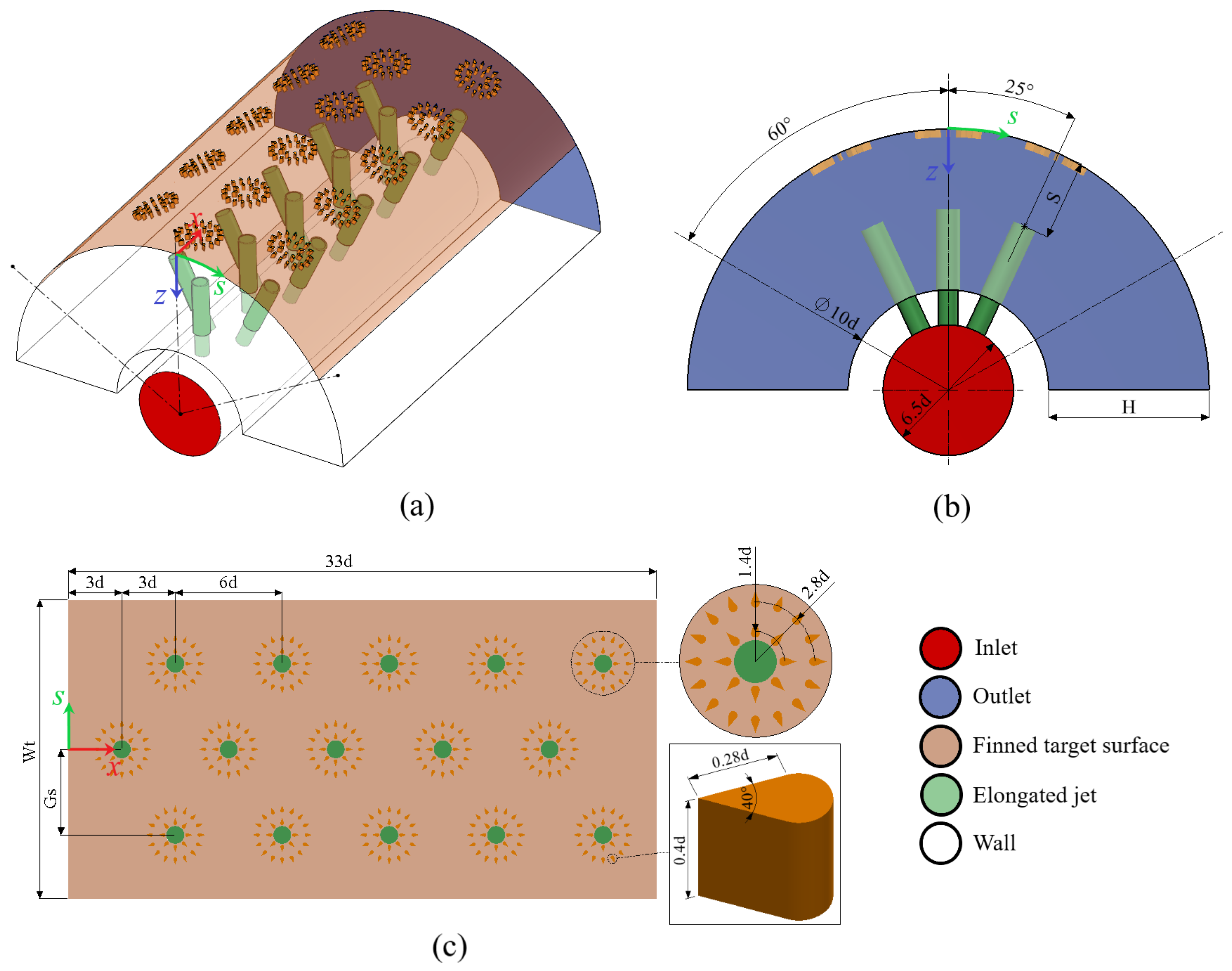
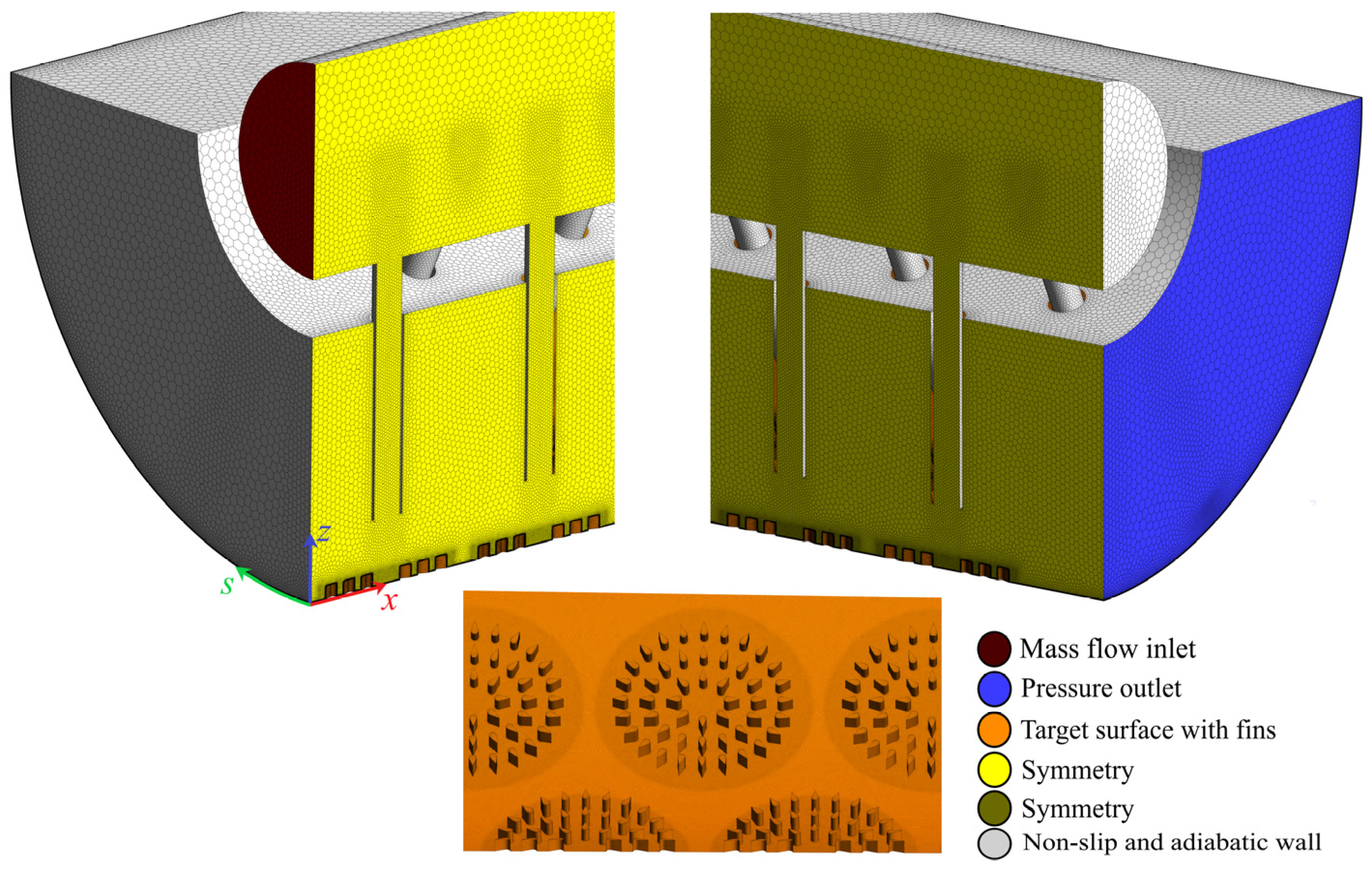
3. Geometry and Boundary Conditions

Figure 1 shows different views of the geometry with the indication of the dimensions. The finned surface and the cooling jets can be recognized. The jets, with a diameter (d) of 5 mm, are positioned on the injection surface, following a 3 × 5 staggered layout. The jets are extended towards the target surface through nozzles, and their wall thickness is 0.2d. On both sides, the jet rows are assembled on the injection surface relative to the z-axis at an angle of 25°. In addition, inclined nozzles with a spacing of 6d between adjacent jets in the streamwise direction are positioned at S/d = 0 and ±2.6.
The arrangement of fins is a crucial factor that significantly influences the heat transfer distribution and temperature uniformity on the test surface. In the physical model, aerofoil fins are attached to the target surface. In addition, one, two, and three rows of circularly positioned fin layouts were investigated.
As shown in Figure 1a, the fluid enters the cooling channel through a circular section with a radius of 16.25 mm. Once it goes through the jets, the process fluid impinges on the target surface and exits the cooling duct in the streamwise direction. Numerical computations are performed for the physical model, considering a turbulent flow regime due to the Re number range of 5000 to 25,000. On the semi-circular curved surface, the measurement region extends ±60° along the s-axis in the z-direction.
Elongated jet holes (S/d = 0.5, 2.0, 4.0, 8.0) are investigated at a constant ratio, H/d = 8.0. G s and W t are the vertical distances of the jets in the lateral direction and target surface width, respectively. G s and W t are dependent on the jet diameter and the injection plate–target surface distance (H) and can be calculated from the equations below. The length in the main flow direction of the target surface is 33d.
W t = 2.094 H + 10.472 d
G s = 0.436 H + 2.182 d
The configuration exhibits a symmetry with respect to the xz plane (Figure 1), which is utilized here to save computational costs. Only half of the geometry is covered by the solution domain, applying a symmetry boundary condition on the xz plane. Further boundary types that occur are inlet, outlet, and walls. At the outlet, a zero-gauge pressure is prescribed along with zero-gradient condition for the remaining quantities. At the walls, the no-slip condition applies for the momentum equations. Additionally, a constant temperature of Tw = 320 K is assumed on the target surface with fins, while the remaining walls are considered adiabatic. The numerical computations were conducted with the SST k-w turbulence model with low-Re corrections. Additionally, the SIMPLEC algorithm was preferred for the pressure–velocity coupling. The governing equations were discretized with a second-order upwind scheme. Details about the governing equations can be found in our previous work [53]. The air’s density, specific heat, dynamic viscosity, and thermal conductivity were 1.094 kg/m3, 1007.4 J/kg.K, 1.7879 × 10⁻⁵ Pa.s and 0.027801 W/m.K, respectively.
At the inlet, constant normal velocities corresponding to different mass flow rates are prescribed. The mass flow rates 2.88 × 10⁻³ kg/s, 8.64 × 10⁻³ kg/s, and 14.4 × 10⁻³ kg/s correspond to Reynolds numbers of 5000, 15,000, and 25,000, respectively, where the Reynolds number is defined based on the jet diameter (d) and bulk jet velocity (U) as
R e = ρ U d μ
where ρ and μ denote the fluid density and molecular dynamic viscosity, respectively.
The inlet static temperature (T0) is kept at the constant value of 300 K. Inlet conditions of the turbulence quantities are derived from assumed values of turbulence intensity and macro-length scale. The inlet turbulence intensities are 4.55%, 3.95%, and 3.73% for the Re = 5000, 15,000, and 25,000, respectively.
The convective heat transfer coefficient (h) is calculated from
h = q T w T o
where q denotes the wall heat flux. The Nusselt number (Nu) is obtained from
N u = h d k
where h and k stand for the heat transfer coefficient and the molecular thermal conductivity, respectively.

3.1. Mesh Independence Analysis

The grid structure plays a crucial role in obtaining accurate results in numerical studies. It is required for the accuracy of the results to create a denser grid structure in the nozzles and target surfaces where velocity and temperature variations are intense. Figure 2 provides a detailed overview of the mesh structure in the computational domain.
Additionally, the figure shows a comprehensive view of the target surface mesh structure. In this study, polyhedral elements are preferred due to their suitability for engineering applications involving complex geometry. As shown in the figure, the grids are more concentrated in the wall jet region and target wall to accurately capture the flow and heat transfer characteristics. The boundary conditions and named selections are also indicated in the figure.
Grid independence analysis was implemented to determine if the solutions exhibited mesh independence behavior. For this reason, the area-averaged Nu number on the smooth target surface was obtained for various mesh structures at H/d = 8.0, S/d = 2.0, and Re = 15,000. The mean Nu number variation corresponding to various grid resolutions is shown in Table 1. As seen in the table, there is only a 0.73% difference in the mean Nu number between Type 3 and Type 4. Based on the observed minor difference between Type 3 and Type 4, the Type 3 structure was used in the computations by neglecting these differences due to the lower computational cost. The so-called y+ values (non-dimensional wall distance) that are relevant for near-wall turbulence modeling are also displayed in the table as area-averaged values. As all grids exhibit values quite close to unity, the y+ values of the Type 3 and Type 4 grids are lower than unity, indicating a quite satisfactory near-wall resolution for the selected grid (Type 3).

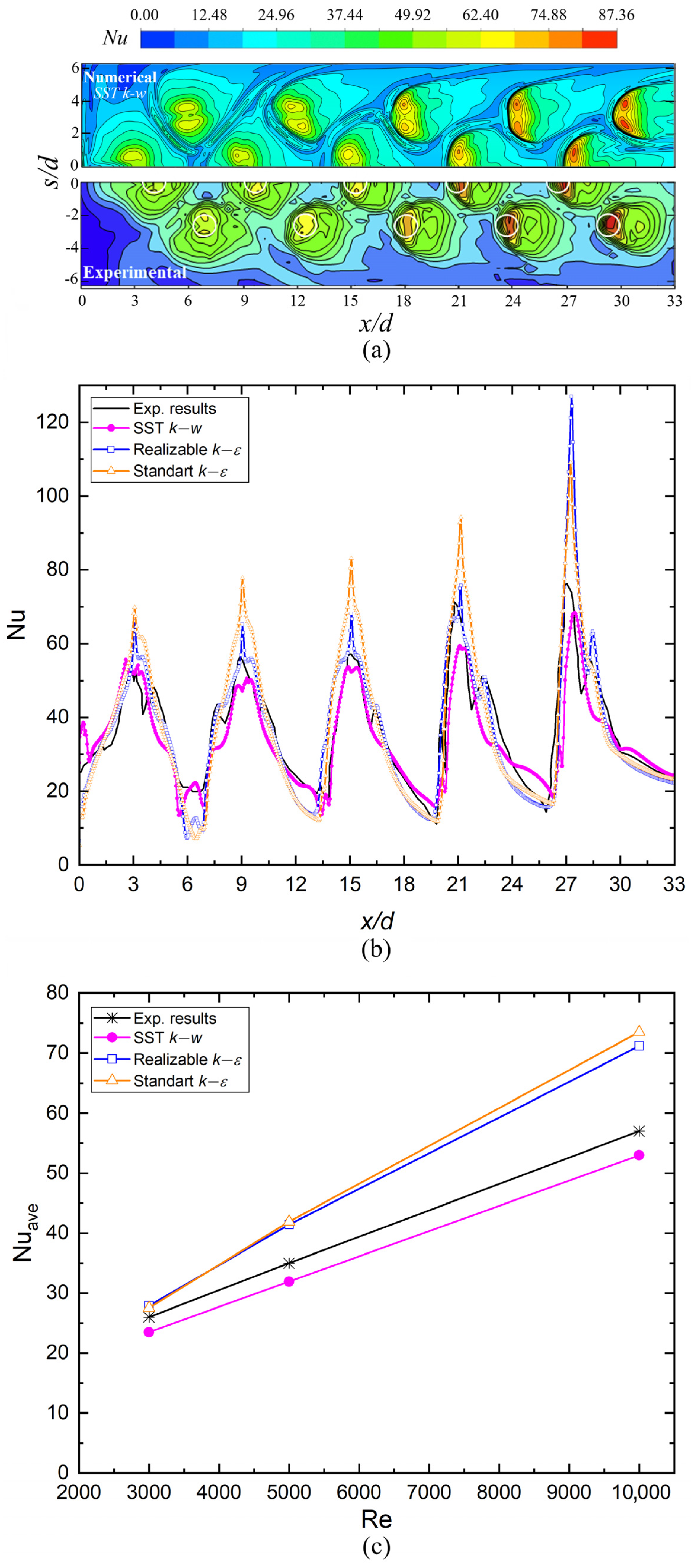
3.2. Validation of the Applied Computational Formulation

Jung et al. [1] presented a study on the effect of the injection angle for an array of impinging jets on a semi-circular surface. Due to the similarity to the present configuration, the results of Jung et al. [1] are used here for validation.
In Figure 3a, the predicted Nusselt number distribution on the smooth surface (for H/d = 1.0, Re = 5000, S/d = 1.0) is compared with the experimental results of Jung et al. [1]. A quite satisfactory agreement is observed.
For the same case, the variation of the local Nusselt number along a line in the axial direction is presented in Figure 3b. In this figure, the results obtained by the standard k-ε model and realizable k-ε model are also displayed. One can see that the predictions obtained by the presently applied SST k-ω model agree quite well with the experimental results, whereas the results of the standard k-ε and realizable k-ε model do not show a good agreement.
The area-averaged Nusselt numbers for a range of Reynolds numbers are displayed in Figure 3c. It can be observed that the present predictions obtained by the SST k-ω model agree quite well with the experimental results, showing a slight underprediction. The maximum deviation of the predictions from the experimental results is observed to be 9.4%. The results obtained by the standard k-ε model and realizable k-ε model show a larger discrepancy from the experimental values, where the overprediction increases with increasing Reynolds number.
For the same geometrical configuration and Re = 5000, the predicted velocity vector field at x/d = 3.0 is compared with the prediction of Jung et al. [1] in Figure 4. Primary and secondary vortices were generated in both studies at nearly the same locations (approximately at S/d ≅ −1.5 and S/d ≅ −6.0).
The validation study presented in this section confirms the adequacy of the presently applied computational procedure.

4. Result and Discussion

4.1. Area-Averaged Nusselt Numbers

The primary purpose of this study is to investigate the effect of combining aerofoil fins, which have different arrangements, with elongated jet hole configurations for improving the heat transfer performance of impingement cooling. In this section, an evaluation was made of the effect of different fin layouts on convective heat transfer along the target surface, as shown in Figure 5: single row (L1), double row (L2), and triple row (L3).
With regard to fin arrangements (L1, L2, L3) and dimensionless nozzle-to-target surface spacings (S/d), the area-averaged Nusselt number (referred to as mean Nu or average Nu hereafter) variations on smooth and finned surfaces at different Re are presented in Figure 6. Total heat transfer was enhanced by arranging two rows of fins and reducing the S/d to 0.5. Additionally, the adverse effect of cross-flow decreased considerably with fins and elongated nozzle combination [61].
The mean Nu for the conventional jet impingement scheme (CIJAC) (S/d = 8.0, without fin configuration) at Re = 25,000 is 53.16. The mean Nu reached 62.21, with an increase of 17.02%, using the layout of L2 for S/d = 8.0. On the other hand, the average Nu on the fin-roughened surface with the layout of L3 increased by 12.91% to 60.03 under the same geometry and flow conditions. The mean Nu on the smooth surface for the elongated hole configuration (S/d = 2.0) is 63.37 at Re = 25,000; it is 75.02 on the finned surface with the layout of L2. An approximately 18.38% increase in heat transfer was observed merely by adding fins to the target surface. Similarly, the mean Nu value is 47.77 for Re = 15,000 and S/d = 0.5 on the smooth surface and is 52.90 and 55.09 for the L1 and L2 fin layouts, respectively. As a result, the percentage increase relative to the smooth surface is 10.73% and 15.33% for L1 and L2.
In addition, the mean Nu is calculated to be 53.16 at Re = 25,000 in the CIJAC scheme. Interestingly, this value increased to 78.53, 81.24, and 80.30 by decreasing S/d to 0.5 in the finned model for the L1, L2, and L3 patterns. Based on these results, the percentage increases in overall heat transfer compared to the conventional impinging model are 47.70%, 52.81%, and 51.04%, respectively. Considering these results, the two-row fin arrangement (L2) produces relatively better results in improving the mean Nu compared to the one-row (L1) and three-row fin arrangements (L3). The mounting of fins on the curved target surface has a significant effect on disrupting the thermal boundary layer, leading to enhanced heat transfer performance in the test region. Increasing the number of fin rows improved turbulence compared to the single-row arrangement. However, after the second row, the increase in friction losses began to prevent the flow through the fins, leading to a diminishing effect on the increase in heat transfer.
The mean Nu variation is significantly affected by the S/d ratio as well as the fin arrangement. A significant increase is generally observed in mean Nu when the dimensionless S/d ratio decreases from 8.0 to 0.5. For instance, in the conventional impinging model, the average Nu is 16.68 on the smooth surface at Re = 5000. At the same Re number, this value for the L2 layout increases by 50.67%, 36.29%, and 27.28% at S/d = 0.5, 2.0, and 4.0, respectively. Likewise, this value for the L3 layout increases by 47.20%, 32.76%, and 21.27% at S/d = 0.5, 2.0, and 4.0.

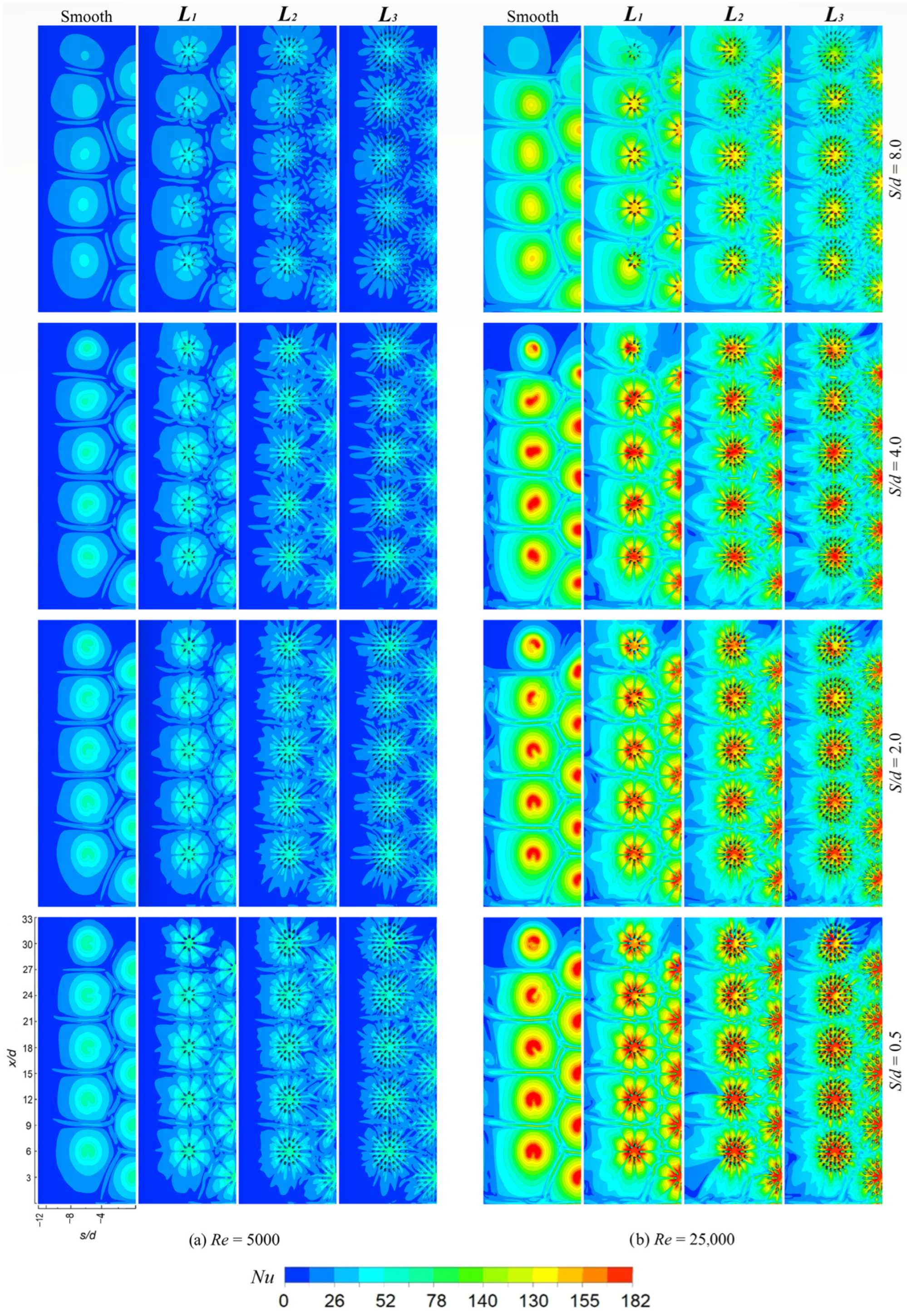
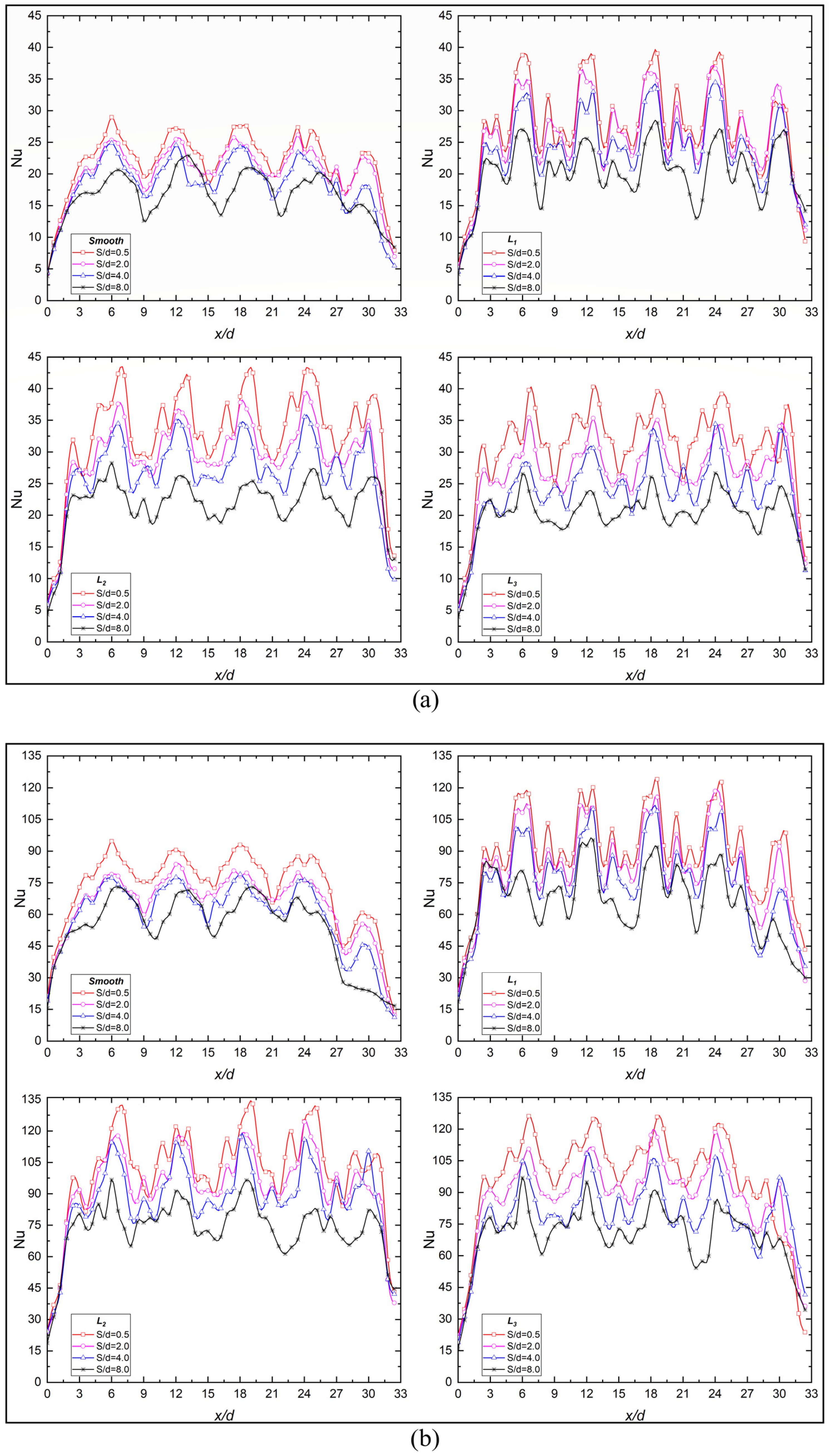
4.2. Local Heat Transfer
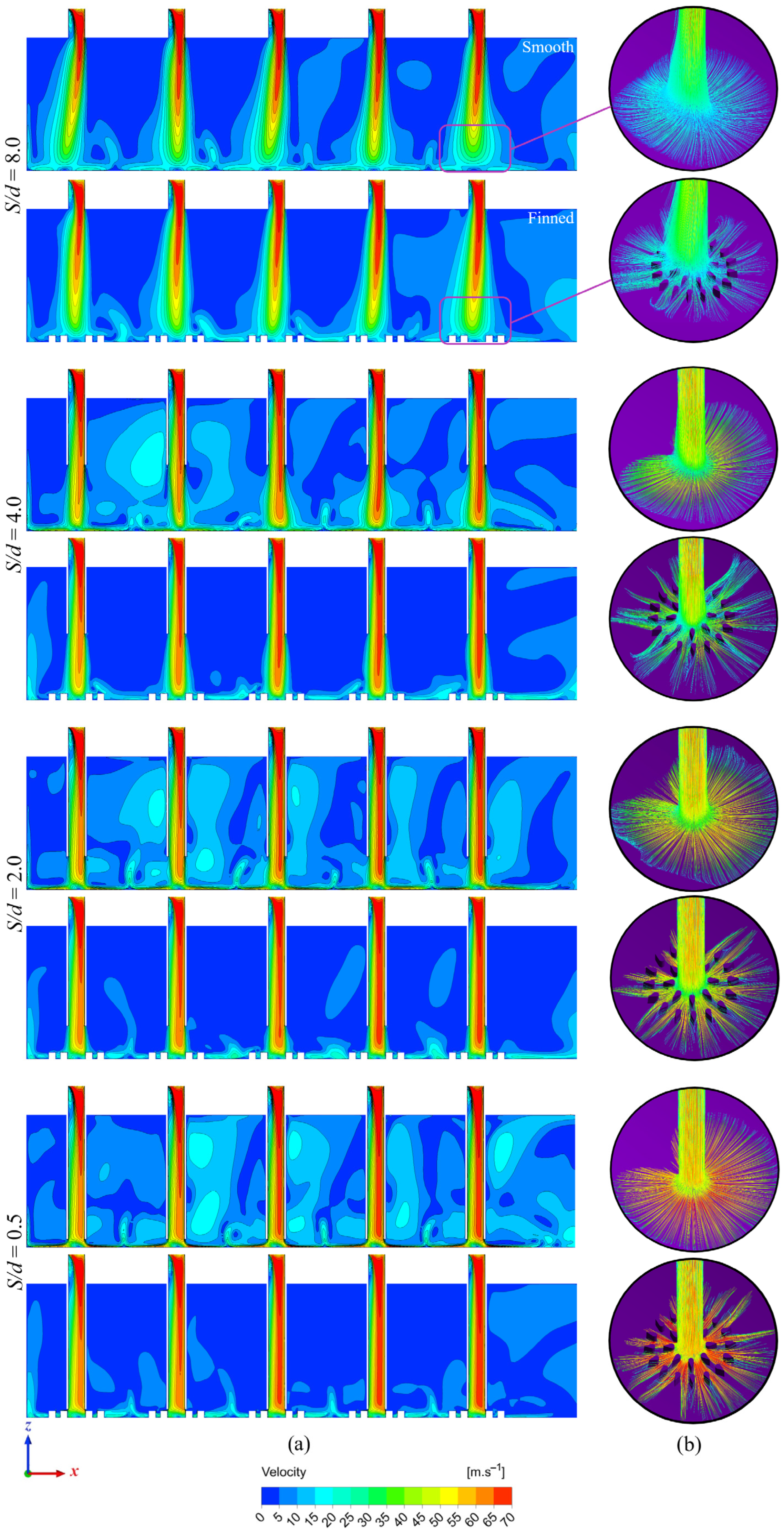
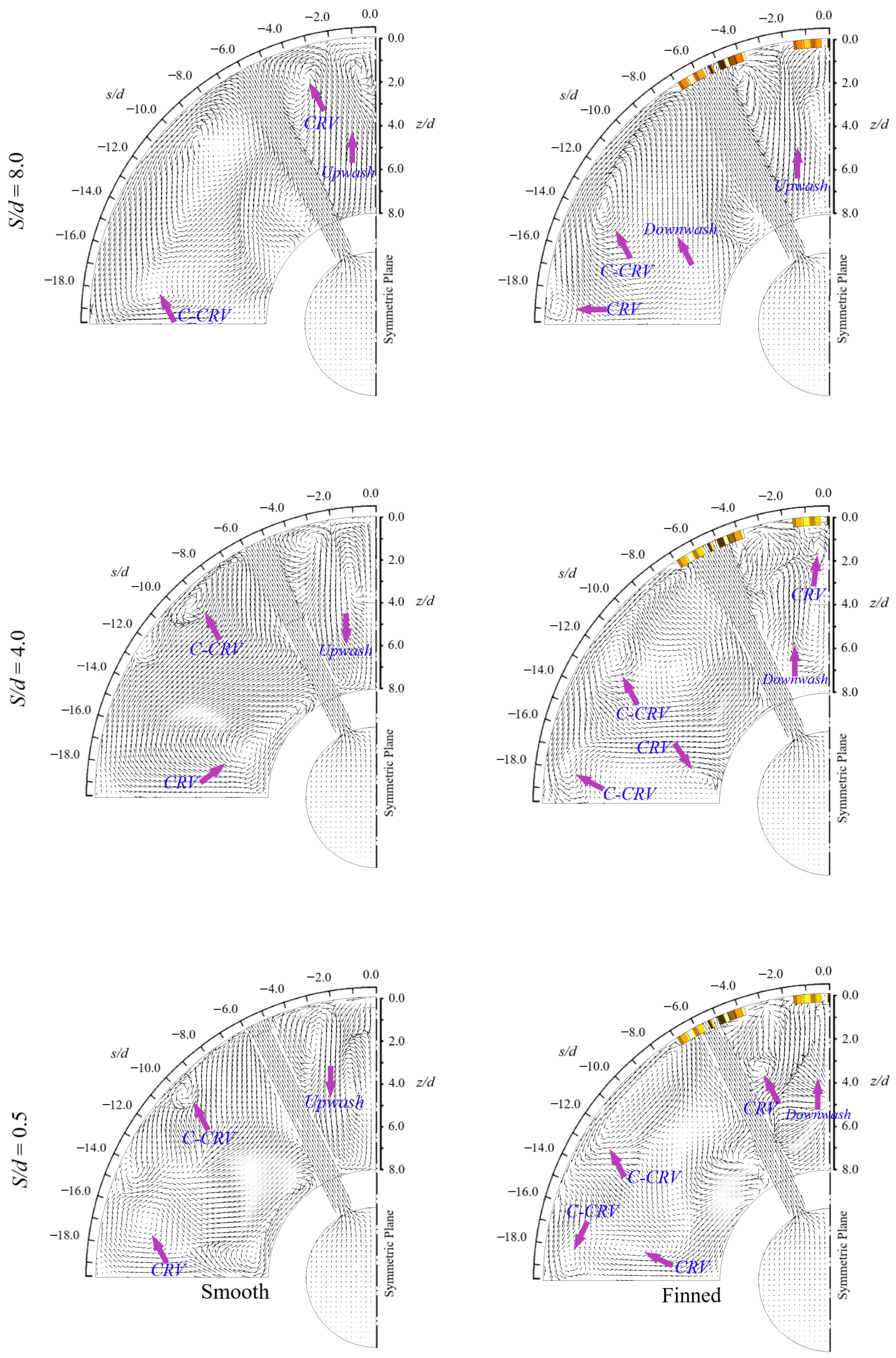
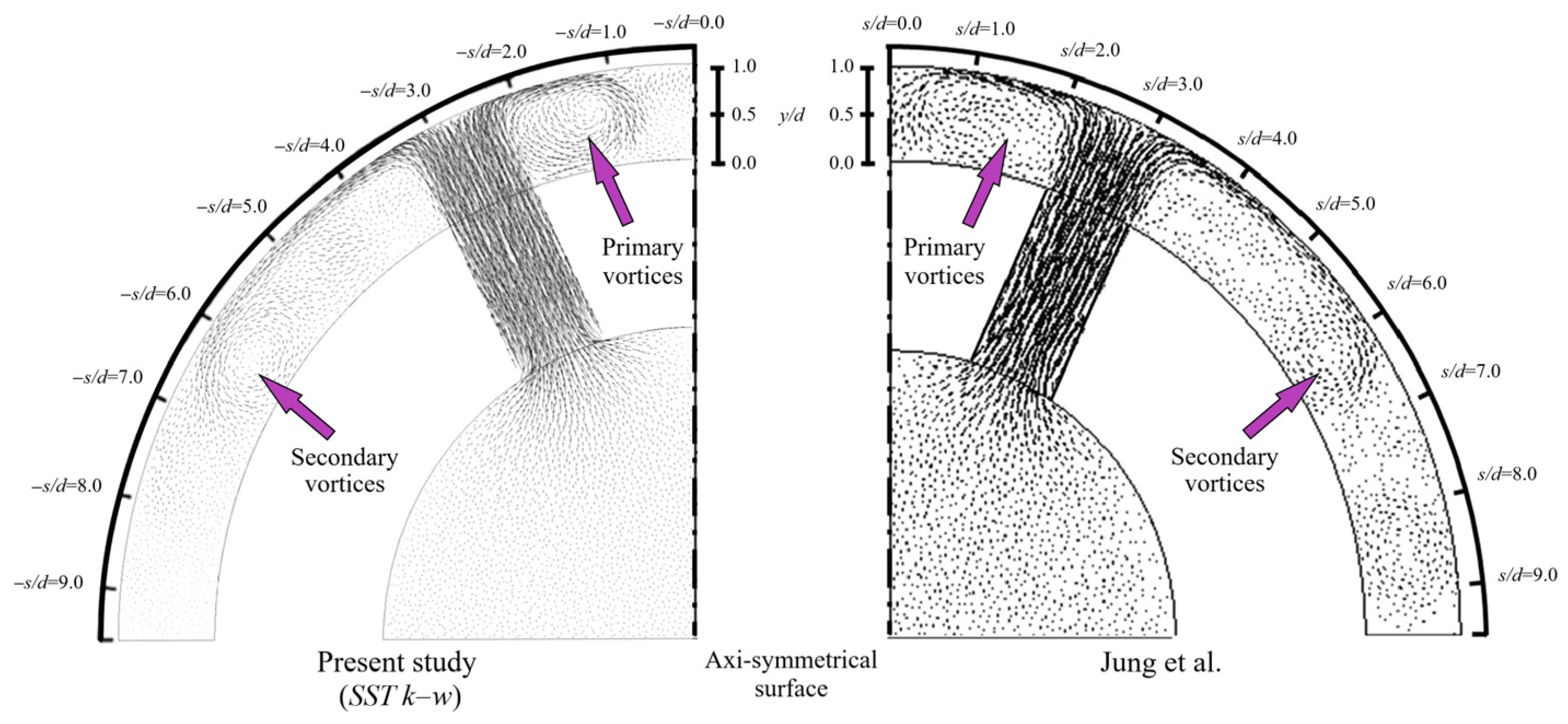
The fluid jet impinging on the target surface and then reversing its direction creates a crossflow region between the injection plate and the target surface. When additional jet streams are introduced in the discharge direction, the flow dynamics can be changed and the behavior of the individual jets impacted. The crossflow velocity refers to the velocity of the fluid in the direction perpendicular to the streamwise direction. In this case, the crossflow velocity gradually increases as the fluid flows from the initial jet impingement location toward the outflow. Jet profiles can bend or deform in the flow direction due to the influence of the crossflow, especially for the high S/d ratio. Elongating the nozzles to the impingement region and introducing surface roughness by adding fins or other protrusions to the target surface can also help to counteract the negative effects of crossflow. The roughened surface disrupts the crossflow and promotes better mixing and heat transfer. This can lead to increased heat transfer rates and more uniform flow distribution, often desirable outcomes in jet impingement systems.
Figure 7 demonstrates the Nu contour plots on smooth and finned target surfaces (L1, L2, and L3) under Re = 5000 and 25,000, respectively. Since the physical model has a plane of symmetry and the fluid and heat flow is homogeneous in the radial direction and not in the longitudinal direction, only half of the target surface domain is given in this section. The interaction between adjacent jet streams decreases the heat transfer rate by producing new stagnation or slower flow regions on the smooth surfaces, as seen in Figure 7. However, the fins contributed to the homogeneous heat transfer distribution on the test region by minimizing the stagnation points between adjacent jets.
When the nozzle-to-target surface spacing ratio is high (S/d > 4.0), the crossflow between the jets and the target surface significantly affects the jet flow, as shown in Figure 7. On the other hand, the presence of fins at all S/d ratios enhances the heat transfer in the final jet zone, especially for the L2 and L3 fin layouts. In the L1 arrangement, this improvement is relatively lower than in L2 and L3. As a result, the dispersion of stagnation regions and improved flow dynamics resulting from using aerofoil fins led to a more uniform heat transfer across the target surface.
The laterally area-averaged Nusselt numbers predicted for different configurations are presented in Figure 8a for Re = 5000 and in Figure 8b for Re = 25,000.
When the results of the smooth surface are carefully examined, it can be concluded that the local Nu decreases significantly with the adverse effect of crossflow, especially in the CIJAC model in the range of 27 < x/d < 37. However, the effect of this developing crossflow was reduced by roughening the surface and using the elongated jets together, achieving a significant improvement in these regions [52,61]. The results reveal that the local Nu on finned surfaces decreases with increasing S/d. At the same time, the highest local Nusselt numbers are achieved for S/d = 0.5, whereas the lowest local Nu number distributions are generally observed at S/d = 8.0. Moreover, the results indicate that the local Nu enhances remarkably for the L2 fin layout, especially for the stagnation and final jet regions. Nevertheless, the L1 fin arrangement does not substantially enhance the local Nusselt numbers. When the elongated jet flow impinges the surface, it creates a stagnation region right at the point of impact, where heat transfer is typically higher. However, the heat transfer considerably decreases on the wall jet and last jet regions compared to jet impingement regions. Fins are added to manipulate the flow towards these regions, reducing the uneven distribution of heat transfer along the streamwise and spanwise directions.

4.3. Flow Features

The contours of velocity magnitude on S/d = 0 in the longitudinal central plane on the smooth and finned surfaces (L2) at Re = 15,000 are shown in Figure 9 (in these plots, the domain within the central circular tube is not displayed). One can observe that there are local recirculation zones at nozzle inlets, caused by the sharp entrance and the abrupt alteration in fluid direction. One can also observe that the induced flow asymmetries persist nearly over the whole nozzle length. These findings indicated a similar axial variation in velocity observed on both concave and flat surfaces [23,31,62]. Since it is outside the potential core region, the flow velocity impinging on the target surface has a reduced impact due to crossflow. With the proposed geometry, shifting the impingement region along the flow direction is minimized, which is caused by the negative effect of cross-flow [63,64], as demonstrated in the literature [52,65]. For example, when compared between the smooth and finned model’s velocity contours, this effect especially appears in the S/d = 4.0 and 8.0 models, as shown in Figure 9a. In other S/d ratios, the effect of elongated jets in crossflow is dominant.
Figure 9b also shows the streamlines for the last jet regions (x/d > 27) on smooth and finned surfaces (L2) at Re = 15,000 to examine the impact of S/d in detail. As shown in the figure, the attachment of the fins influences the flow characteristics, leading to changes in streamlines. Streamlines have a tendency to be smoother and more streamlined without fins. The irregularities caused by the fins created flow turbulence, resulting in separation zones and vortices. When the flow impinges the fins, streamlines become more complex compared to the smooth surface, since this changes the directions and speeds of the fluid. When the flow impinges on the fins, the streamlines become more complex compared to the smooth surface, changing direction and speed due to the fluid’s interaction. The finned surface produces vortices and turbulence, leading to altered streamlines, improving boundary layer attachment, reducing the negative effects of adjacent jets, and strengthening the fluid–surface contact.
Moreover, the leading edges of the fins could experience substantial velocity gradients due to the relationship between the fins and elongated jet holes. Heat transfer is expected to be higher in these regions [66]. As a result, the elongated hole and fin geometry led to complex flow patterns on the surface due to flow separation. Additionally, the generation of vortices at the leading edges of the fins provided more heat transfer in these regions than vortices on the trailing edge and top side. Besides, the emergence of strong velocity fluctuations near the fins contributed to enhanced heat transfer. The velocity fluctuations occurring near the fins can be seen in Figure 10 in the velocity vectors at the intersections of S/d = −2.0 and z/d = 2.0. Additionally, in finned surface models with elongated jets, downward flow regions were observed at the intersections of S/d = −2.0 and z/d = 4.0.
Velocity vector plots for the nozzle hole configurations on both smooth and fin-roughened (with L2 design) models on x/d = 12 are shown in Figure 10. Due to the collision between the neighboring jet stream and the wall, clockwise rotating vortices (CRV) were generated close to the S/d ≅ −3.5 region for almost all configurations. Using elongated nozzle holes and roughening the surface improved the fluid circulation in the cooling channel for all configurations. As a result, the counter-clockwise rotating vortex (C-CRV) formation on smooth surfaces was monitored around S/d ≅ −10.0, but it shifted to S/d ≅ −14.0 when the surface was roughened with fins. This fluid attachment to the surface was enhanced by fins, reducing the dead flow zone. Upwash vectors occurring on the smooth surface at the location of S/d = −1.0 were replaced by downwash vectors in the finned models. This could cause more flow to be directed to the surface and increase heat transfer. Consequently, the heat transfer region on the surface expanded, leading to improved heat transfer uniformity on the curved surface.

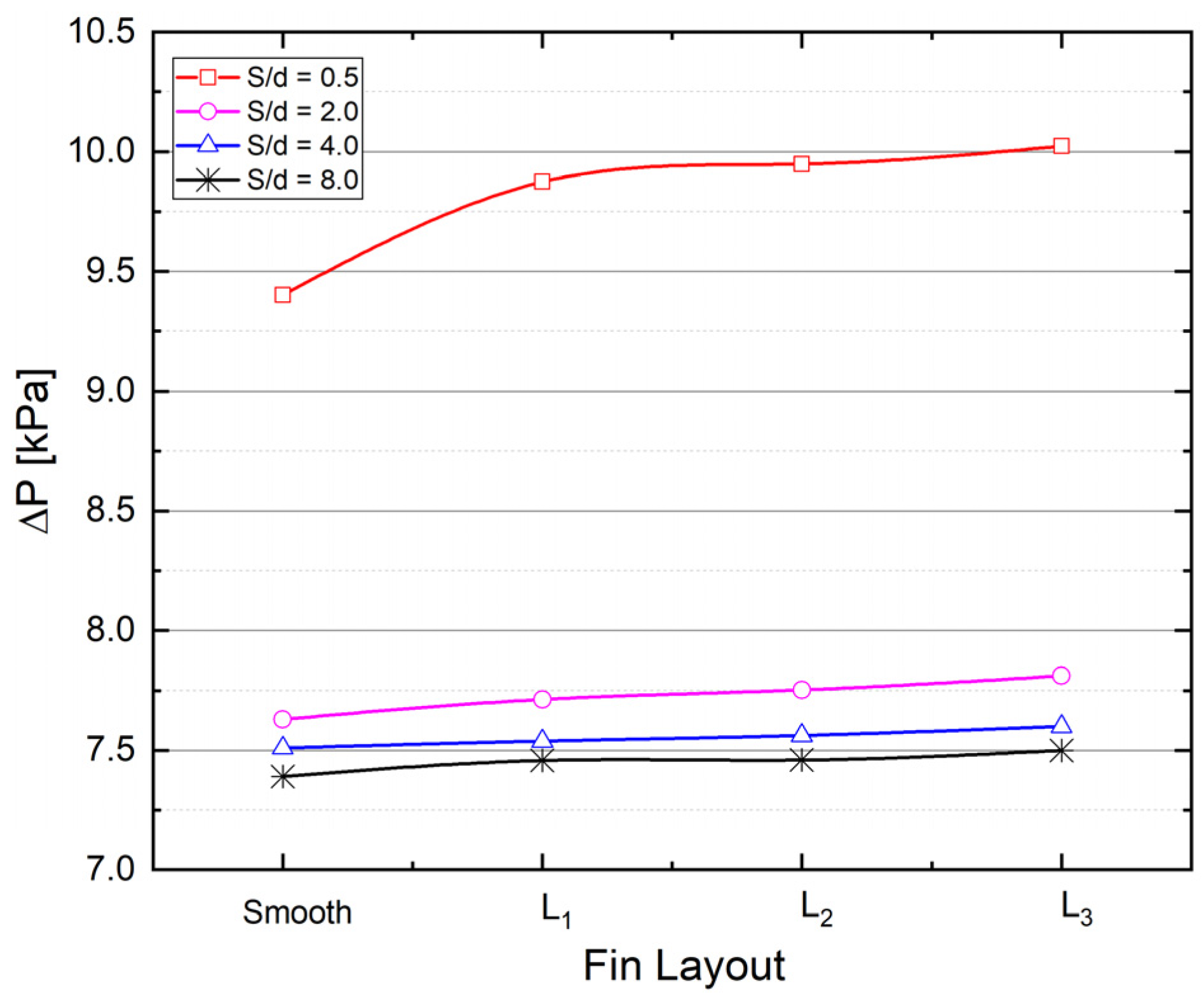
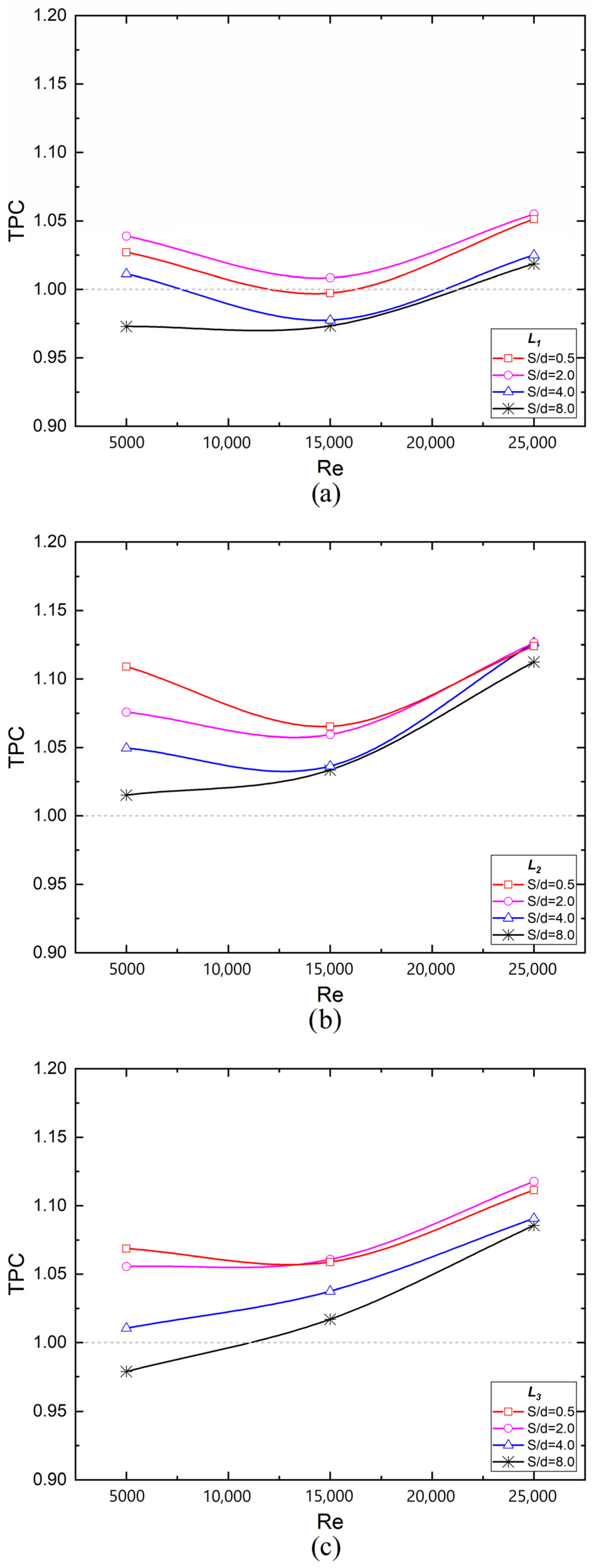
4.4. Pressure Drop and Thermal Performance Criterion

Several methods are utilized to improve the efficiency of jet impingement cooling designs. Some include altering the dimensions of the nozzle holes, adjusting the positions of the nozzles, or roughening the target surface. However, it is essential to evaluate the thermal performance criterion (TPC) since these variations may also augment the pressure drop in cases involving heat transfer enhancement. The increase in pressure drop also increases the compressor work required for cooling. The required compressor work is calculated by following equation.
W ˙ c o m p = P × V ˙
where W ˙ c o m p is the required compressor work, V ˙ is the volume flow rate of the air and P is the pressure difference between the inlet and the outlet.
In Figure 11, pressure drops are examined based on the fin layouts and S/d ratios for Re = 25,000. When the S/d decreases, the pressure drop increases. In particular, reducing the S/d to 0.5 significantly increases the pressure drop on both smooth and fin-roughened surfaces. For example, for S/d = 0.5 on a smooth surface, the pressure drop shows a 25.6% increase compared to the conventional impinging jet model. The maximum increase in pressure drop for other S/d ratios occurs at S/d = 2.0, with a value of 5.6%, which can be considered negligible. Moreover, the effect of roughening the target surface on the increase in pressure drop is relatively low. At Re = 25,000 and S/d = 0.5, a maximum pressure drop of 6.6% is calculated between the smooth and L3 fin arrangement. Additionally, the effect of fins on pressure drop is negligible for S/d = 2.0, 4.0, and 8.0. Maximum pressure drops are observed in the L3 fin arrangement for all S/d ratios. In contrast, the lowest pressure drops are obtained in smooth concave surface configurations. As a result, elongated jets significantly increase heat transfer while also increasing pressure drop. For these reasons, considering the TPC is important.
The TPC is a measure [67,68] that accounts for the interaction between heat transfer and a system’s hydraulic performance. TPC is represented as a function of the friction factor (f) and the area-averaged Nu:
T P C = N u f N u s / f f f s 1 / 3
where the variables are related to two different configurations of jet impingement: a staggered conventional jet array with a smooth curved surface (represented by f s and N u s ) and a staggered elongated jet array with a fin-roughened curved surface (symbolized by f f and N u f ).
To increase the heat transfer efficiency of the traditional staggered jet impingement with a smooth curved surface, the injection holes were elongated towards the target plate, and the effect of one-row, two-row, and three-row aerofoil fin arrangements on heat transfer was investigated on the target surfaces. The results indicated that the increasing nozzle length and roughening of the surface with fin elements increased mean Nu numbers for all designs as well as pressure drops. Therefore, TPC was investigated to assess the feasibility of integrating elongated nozzles and fins for the jet impingement system. When the TPC is higher than one, the heat transfer enhancement is more dominant than the increase in required compressor work. According to the TPC values, all tested fin arrangements except the L1 for all Re numbers are feasible, especially when S/d is less than or equal to 2.0, as shown in Figure 12. The highest thermal performance factor for fin arrangements is obtained in the L2 design. However, it is observed that the TPC values decreased after the transition from the L2 fin layout to the L3 fin layout due to the increased contact surface area of fins and, accordingly, increased friction factor. Additionally, the L1 fin layout is unsuitable for roughened curved surfaces due to insufficient heat transfer enhancement and decreased TPC values. In conclusion, the combination of extended nozzles and fins is advantageous in balancing heat transfer enhancement and pressure drop increase when the S/d is kept around 2.0 for the L2 fin layout.

5. Conclusions

In jet impingement cooling ducts, the concave geometry of the target surface and the interaction between adjacent jets leading to the stagnation points may naturally cause challenges in achieving uniform cooling and efficient heat transfer. To eliminate these disadvantages, a number of novel designs have been proposed to increase and uniformize the heat transfer occurring in the conventional jet impingement cooling geometry used in this study (with a non-extended jet and smooth surface). The specific results of this study can be listed as follows.
  • Mounting aerofoil fins on the surface increased overall heat transfer through the interaction between the hot surface and processing fluid. For example, an approximately 18.38% increase in heat transfer was observed only by adding fins to the target surface compared to the smooth surface at S/d = 2.0 with the L2 configuration. By decreasing S/d to 0.5 in the finned model, the best increase in overall heat transfer relative to the conventional jet impingement model was 52.81%, obtained for the L2 design.
  • Interaction between adjacent jet streams produces new stagnation or slower flow zones on smooth surfaces, reducing the heat transfer rate. However, the fins led to homogeneous heat transfer distribution on the surface by minimizing stagnation points between adjacent jets. Consequently, using aerofoil fins contributed to a more uniform heat transfer across the target surface.
  • Both elongated nozzle holes and aerofoil fins enhance heat transfer on the target surface. Fins provide a more homogeneous local heat transfer along the flow direction by preventing non-uniform heat transfer distribution between jet regions. On the other hand, elongated jets enhance heat transfer in the stagnation region rather than heat transfer uniformity.
  • The two-row fin layout (L2) produces relatively better results in terms of both improving the mean Nu numbers and TPC values compared to the one-row (L1) and three-row fin arrangement (L3). According to the TPC values, the combination of extended nozzles and mounting fins is feasible for balancing heat transfer enhancement and pressure drop increase when the S/d ≤ 2.0 for all tested fin layouts except L1.

Author Contributions

Conceptualization, O.Y. and A.C.B.; methodology, A.Ü.T., A.C.B. and Ü.U.; software, A.Ü.T.; validation, O.Y. and A.Ü.T.; formal analysis, O.Y.; investigation, O.Y. and U.D.; data curation, Ü.U.; writing—original draft preparation, O.Y.; writing—review and editing, O.Y., A.C.B. and U.D.; visualization, O.Y.; supervision, U.D. and Ü.U. All authors have read and agreed to the published version of the manuscript.

Funding

This research received no external funding.

Data Availability Statement

Data is contained within the article.

Conflicts of Interest

The authors declare no conflicts of interest.

References

  1. Jung, E.Y.; Park, C.U.; Lee, D.H.; Kim, K.M.; Cho, H.H. Effect of the Injection Angle on Local Heat Transfer in a Showerhead Cooling with Array Impingement Jets. Int. J. Therm. Sci. 2018, 124, 344–355. [Google Scholar] [CrossRef]
  2. Herrero Martin, R.; Buchlin, J.M. Jet Impingement Heat Transfer from Lobed Nozzles. Int. J. Therm. Sci. 2011, 50, 1199–1206. [Google Scholar] [CrossRef]
  3. Hwang, S.D.; Lee, C.H.; Cho, H.H. Heat Transfer and Flow Structures in Axisymmetric Impinging Jet Controlled by Vortex Pairing. Int. J. Heat Fluid Flow 2001, 22, 293–300. [Google Scholar] [CrossRef]
  4. Laroche, E.; Donjat, D.; Reulet, P. A Combined Experimental and Numerical Characterization of the Flowfield and Heat Transfer around a Multiperforated Plate with Compound Angle Injection. Energies 2021, 14, 613. [Google Scholar] [CrossRef]
  5. Yong, S.; Zhang, J.Z.; Xie, G.N. Convective Heat Transfer for Multiple Rows of Impinging Air Jets with Small Jet-to-Jet Spacing in a Semi-Confined Channel. Int. J. Heat Mass Transf. 2015, 86, 832–842. [Google Scholar] [CrossRef]
  6. Fenot, M.; Vullierme, J.-J.; Dorignac, E. Local Heat Transfer Due to Several Configurations of Circular Air Jets Impinging on a Flat Plate with and without Semi-Confinement. Int. J. Therm. Sci. 2005, 44, 665–675. [Google Scholar] [CrossRef]
  7. Huber, A.M.; Viskanta, R. Effect of Jet-Jet Spacing on Convective Heat Transfer to Confined, Impinging Arrays of Axisymmetric Air Jets. Int. J. Heat Mass Transf. 1994, 37, 2859–2869. [Google Scholar] [CrossRef]
  8. Yan, W.M.; Mei, S.C.; Liu, H.C.; Soong, C.Y.; Yang, W.J. Measurement of Detailed Heat Transfer on a Surface under Arrays of Impinging Elliptic Jets by a Transient Liquid Crystal Technique. Int. J. Heat Mass Transf. 2004, 47, 5235–5245. [Google Scholar] [CrossRef]
  9. Jung, E.Y.; Park, C.U.; Lee, D.H.; Kim, K.M.; Woo, T.K.; Cho, H.H. Heat Transfer Characteristics of an Angled Array Impinging Jet on a Concave Duct. Proc. ASME Turbo Expo 2012, 4, 601–607. [Google Scholar] [CrossRef]
  10. Singh, A.; Prasad, B.V.S.S.S. Influence of Novel Equilaterally Staggered Jet Impingement over a Concave Surface at Fixed Pumping Power. Appl. Therm. Eng. 2019, 148, 609–619. [Google Scholar] [CrossRef]
  11. Bu, X.; Peng, L.; Lin, G.; Bai, L.; Wen, D. Experimental Study of Jet Impingement Heat Transfer on a Variable-Curvature Concave Surface in a Wing Leading Edge. Int. J. Heat Mass Transf. 2015, 90, 92–101. [Google Scholar] [CrossRef]
  12. Rückert, F.U.; Sauer, M.; Liimatainen, T.; Hübner, D. The Thermal Twin BT—Digital Twin Development: An Introduction to Simcenter Amesim; Rückert, F.U., Sauer, M., Liimatainen, T., Hübner, D., Eds.; Springer Nature Switzerland: Cham, Switzerland, 2023; pp. 47–57. ISBN 978-3-031-25692-9. [Google Scholar]
  13. Wright, I.G.; Gibbons, T.B. Recent Developments in Gas Turbine Materials and Technology and Their Implications for Syngas Firing. Int. J. Hydrogen Energy 2007, 32, 3610–3621. [Google Scholar] [CrossRef]
  14. Bhattacharyya, S.; Benim, A.C.; Chattopadhyay, H.; Banerjee, A. Experimental and Numerical Analysis of Forced Convection in a Twisted Tube. Therm. Sci. 2019, 23, 1043–1052. [Google Scholar] [CrossRef]
  15. Bhattacharyya, S.; Benim, A.C.; Pathak, M.; Chamoli, S.; Gupta, A. Thermohydraulic Characteristics of Inline and Staggered Angular Cut Baffle Inserts in the Turbulent Flow Regime. J. Therm. Anal. Calorim. 2020, 140, 1519–1536. [Google Scholar] [CrossRef]
  16. Chyu, M.K. Recent Advances in Turbine Heat Transfer-with a View of Transition to Coal-Gas Based Systems. J. Heat Transf. 2012, 134, 031006. [Google Scholar] [CrossRef]
  17. Ren, Z.; Yang, X.; Lu, X.; Li, X.; Ren, J. Experimental Investigation of Micro Cooling Units on Impingement Jet Array Flow Pressure Loss and Heat Transfer Characteristics. Energies 2021, 14, 4757. [Google Scholar] [CrossRef]
  18. Allauddin, U.; Uddin, N.; Weigand, B. Heat Transfer Enhancement by Jet Impingement on a Flat Surface with Detached-Ribs under Cross-Flow Conditions. Numer. Heat Transf. Part A Appl. 2013, 63, 921–940. [Google Scholar] [CrossRef]
  19. Behnia, M.; Parneix, S.; Durbin, P.A. Prediction of Heat Transfer in an Axisymmetric Turbulent Jet Impinging on a Flat Plate. Int. J. Heat Mass Transf. 1998, 41, 1845–1855. [Google Scholar] [CrossRef]
  20. Lee, S.-J.; Lee, J.-H.; Lee, D.-H. Local Heat Transfer Measurements from an Elliptic Jet Impinging on a Flat Plate Using Liquid Crystal. Int. J. Heat Mass Transf. 1994, 37, 967–976. [Google Scholar] [CrossRef]
  21. Kercher, D.M.; Tabakoff, W. Heat Transfer by a Square Array of Round Air Jets Impinging Perpendicular to a Flat Surface Including the Effect of Spent Air. J. Eng. Power 1970, 92, 73–82. [Google Scholar] [CrossRef]
  22. Tan, L.; Zhang, J.Z.; Xu, H.S. Jet Impingement on a Rib-Roughened Wall inside Semi-Confined Channel. Int. J. Therm. Sci. 2014, 86, 210–218. [Google Scholar] [CrossRef]
  23. Tong, F.; Gou, W.; Zhao, Z.; Gao, W.; Li, H.; Li, L. Numerical Investigation of Impingement Heat Transfer on Smooth and Roughened Surfaces in a High-Pressure Turbine Inner Casing. Int. J. Therm. Sci. 2020, 149, 106186. [Google Scholar] [CrossRef]
  24. Caliskan, S. Flow and Heat Transfer Characteristics of Transverse Perforated Ribs under Impingement Jets. Int. J. Heat Mass Transf. 2013, 66, 244–260. [Google Scholar] [CrossRef]
  25. Katti, V.; Prabhu, S.V. Heat Transfer Enhancement on a Flat Surface with Axisymmetric Detached Ribs by Normal Impingement of Circular Air Jet. Int. J. Heat Fluid Flow 2008, 29, 1279–1294. [Google Scholar] [CrossRef]
  26. Xie, G.; Liu, X.; Yan, H.; Qin, J. Turbulent Flow Characteristics and Heat Transfer Enhancement in a Square Channel with Various Crescent Ribs on One Wall. Int. J. Heat Mass Transf. 2017, 115, 283–295. [Google Scholar] [CrossRef]
  27. Chyu, M.K. Heat Transfer and Pressure Drop for Short Pin-Fin Arrays with Pin-Endwall Fillet. Proc. ASME Turbo Expo 1989, 4, 926–932. [Google Scholar] [CrossRef]
  28. Singh, P.; Zhang, M.; Ahmed, S.; Ramakrishnan, K.R.; Ekkad, S. Effect of Micro-Roughness Shapes on Jet Impingement Heat Transfer and Fin-Effectiveness. Int. J. Heat Mass Transf. 2019, 132, 80–95. [Google Scholar] [CrossRef]
  29. Bai, W.; Chen, W.; Yang, L.; Chyu, M.K. Numerical Investigation on Heat Transfer and Pressure Drop of Pin-Fin Array under the Influence of Rib Turbulators Induced Vortices. Int. J. Heat Mass Transf. 2019, 129, 735–745. [Google Scholar] [CrossRef]
  30. Hadipour, A.; Rajabi Zargarabadi, M.; Dehghan, M. Effect of Micro-Pin Characteristics on Flow and Heat Transfer by a Circular Jet Impinging to the Flat Surface. J. Therm. Anal. Calorim. 2020, 140, 943–951. [Google Scholar] [CrossRef]
  31. Wan, C.; Rao, Y.; Chen, P. Numerical Predictions of Jet Impingement Heat Transfer on Square Pin-Fin Roughened Plates. Appl. Therm. Eng. 2015, 80, 301–309. [Google Scholar] [CrossRef]
  32. Kannan, B.T.; Sundararaj, S. Steady State Jet Impingement Heat Transfer from Axisymmetric Plates with and without Grooves. Procedia Eng. 2015, 127, 25–32. [Google Scholar] [CrossRef]
  33. Liu, Y.H.; Song, S.J.; Lo, Y.H. Jet Impingement Heat Transfer on Target Surfaces with Longitudinal and Transverse Grooves. Int. J. Heat Mass Transf. 2013, 58, 292–299. [Google Scholar] [CrossRef]
  34. Su, L.M.; Chang, S.W. Detailed Heat Transfer Measurements of Impinging Jet Arrays Issued from Grooved Surfaces. Int. J. Therm. Sci. 2002, 41, 823–841. [Google Scholar] [CrossRef]
  35. Nagesha, K.; Srinivasan, K.; Sundararajan, T. Enhancement of Jet Impingement Heat Transfer Using Surface Roughness Elements at Different Heat Inputs. Exp. Therm. Fluid Sci. 2020, 112, 109995. [Google Scholar] [CrossRef]
  36. van Hout, R.; Rinsky, V.; Sasson, N.; Hershcovich, C.; Tshuva, M.; Grobman, Y.J. Axisymmetric Jet Impingement on a Dimpled Surface: Effect of Impingement Location on Flow Field Characteristics. Int. J. Heat Fluid Flow 2018, 74, 53–64. [Google Scholar] [CrossRef]
  37. Sriromreun, P.; Sriromreun, P. Experimental and Numerical Studies of Heat Transfer Characteristics for Impinging Jet on Dimple Surfaces. Chem. Eng. Trans. 2018, 70, 1273–1278. [Google Scholar] [CrossRef]
  38. Celik, N. Effects of Dimples’ Arrangement Style of Rough Surface and Jet Geometry on Impinging Jet Heat Transfer. Heat Mass Transf. Stoffuebertragung 2020, 56, 339–354. [Google Scholar] [CrossRef]
  39. Vinze, R.; Khade, A.; Kuntikana, P.; Ravitej, M.; Suresh, B.; Kesavan, V.; Prabhu, S.V. Effect of Dimple Pitch and Depth on Jet Impingement Heat Transfer over Dimpled Surface Impinged by Multiple Jets. Int. J. Therm. Sci. 2019, 145, 105974. [Google Scholar] [CrossRef]
  40. Li, D.; Zuo, W.; Li, Q.; Zhang, G.; Zhou, K.; E, J. Effects of Pulsating Flow on the Performance of Multi-Channel Cold Plate for Thermal Management of Lithium-Ion Battery Pack. Energy 2023, 273, 127250. [Google Scholar] [CrossRef]
  41. Zuo, W.; Zhang, Y.; E, J.; Li, J.; Li, Q.; Zhang, G. Performance Comparison between Single S-Channel and Double S-Channel Cold Plate for Thermal Management of a Prismatic LiFePO4 Battery. Renew. Energy 2022, 192, 46–57. [Google Scholar] [CrossRef]
  42. Zhang, Y.; Zuo, W.; E, J.; Li, J.; Li, Q.; Sun, K.; Zhou, K.; Zhang, G. Performance Comparison between Straight Channel Cold Plate and Inclined Channel Cold Plate for Thermal Management of a Prismatic LiFePO4 Battery. Energy 2022, 248, 123637. [Google Scholar] [CrossRef]
  43. Zuo, W.; Zhang, Y.; E, J.; Huang, Y.; Li, Q.; Zhou, K.; Zhang, G. Effects of Multi-Factors on Performance of an Improved Multi-Channel Cold Plate for Thermal Management of a Prismatic LiFePO4 Battery. Energy 2022, 261, 125384. [Google Scholar] [CrossRef]
  44. Li, J.; Zuo, W.; E, J.; Zhang, Y.; Li, Q.; Sun, K.; Zhou, K.; Zhang, G. Multi-Objective Optimization of Mini U-Channel Cold Plate with SiO2 Nanofluid by RSM and NSGA-II. Energy 2022, 242, 123039. [Google Scholar] [CrossRef]
  45. Bhaumik, M.; Dhanawade, K.; Sur, A. Materials Today: Proceedings A Numerical Model Analysis on Perforated Aerofoil Shaped Pin Fin Arrays in Heat Dissipation Enhancement, Pressure Drop and Optimization. Mater. Today Proc. 2023, 92, 1319–1333. [Google Scholar] [CrossRef]
  46. Wan, C.; Rao, Y.; Zhang, X. Numerical Investigation of Impingement Heat Transfer on a Flat and Square Pin-Fin Roughened Plates. In Volume 3A: Heat Transfer; American Society of Mechanical Engineers: San Antonio, TX, USA, 2013. [Google Scholar]
  47. Brakmann, R.; Chen, L.; Weigand, B.; Crawford, M. Experimental and Numerical Heat Transfer Investigation of an Impinging Jet Array on a Target Plate Roughened by Cubic Micro Pin Fins. J. Turbomach. 2016, 138, 111010. [Google Scholar] [CrossRef]
  48. Ndao, S.; Peles, Y.; Jensen, M.K. Experimental Investigation of Flow Boiling Heat Transfer of Jet Impingement on Smooth and Micro Structured Surfaces. Int. J. Heat Mass Transf. 2012, 55, 5093–5101. [Google Scholar] [CrossRef]
  49. Jin, W.; Wu, J.; Jia, N.; Lei, J.; Ji, W.; Xie, G. Effect of Shape and Distribution of Pin-Fins on the Flow and Heat Transfer Characteristics in the Rectangular Cooling Channel. Int. J. Therm. Sci. 2021, 161, 106758. [Google Scholar] [CrossRef]
  50. Ravanji, A.; Zargarabadi, M.R. Effects of Pin-Fin Shape on Cooling Performance of a Circular Jet Impinging on a Flat Surface. Int. J. Therm. Sci. 2021, 161, 106684. [Google Scholar] [CrossRef]
  51. Yalçınkaya, O.; Durmaz, U.; Tepe, A.Ü.; Uysal, Ü.; Özel, M.B. Assessment of Convective Heat Transfer Characteristics for Elliptical-Shaped Pin-Roughened Surface for the Jet Impingement Cooling. ASME J. Heat Mass Transf. 2023, 145, 022301. [Google Scholar] [CrossRef]
  52. Tepe, A.Ü.; Yetişken, Y.; Uysal, Ü.; Arslan, K. Experimental and Numerical Investigation of Jet Impingement Cooling Using Extended Jet Holes. Int. J. Heat Mass Transf. 2020, 158, 119945. [Google Scholar] [CrossRef]
  53. Yalçınkaya, O.; Durmaz, U.; Tepe, A.Ü.; Uysal, Ü.; Özel, M.B. Effect of Slot-Shaped Pins on Heat Transfer Performance in the Extended Jet Impingement Cooling. Int. J. Therm. Sci. 2022, 179, 107698. [Google Scholar] [CrossRef]
  54. Ravanji, A.; Zargarabadi, M.R. Effects of Elliptical Pin-Fins on Heat Transfer Characteristics of a Single Impinging Jet on a Concave Surface. Int. J. Heat Mass Transf. 2020, 152, 119532. [Google Scholar] [CrossRef]
  55. Benim, A.C. Finite Element Analysis of Confined Turbulent Swirling Flows. Int. J. Numer. Methods Fluids 1990, 11, 697–717. [Google Scholar] [CrossRef]
  56. Xia, J.L.; Smith, B.L.; Benim, A.C.; Schmidli, J.; Yadigaroglu, G. Effect of Inlet and Outlet Boundary Conditions on Swirling Flows. Comput. Fluids 1997, 26, 811–823. [Google Scholar] [CrossRef]
  57. Wilcox, D.C. Reassessment of the Scale-Determining Equation for Advanced Turbulence Models. AIAA J. 1988, 26, 1299–1310. [Google Scholar] [CrossRef]
  58. Menter, F.R. Two-Equation Eddy-Viscosity Turbulence Models for Engineering Applications. AIAA J. 1994, 32, 1598–1605. [Google Scholar] [CrossRef]
  59. Penumadu, P.S.; Rao, A.G. Numerical Investigations of Heat Transfer and Pressure Drop Characteristics in Multiple Jet Impingement System. Appl. Therm. Eng. 2017, 110, 1511–1524. [Google Scholar] [CrossRef]
  60. Lu, Q.; Muthukumar, R.; Ge, H.; Parameswaran, S. Numerical Study of a Rotating Liquid Jet Impingement Cooling System. Int. J. Heat Mass Transf. 2020, 163, 120446. [Google Scholar] [CrossRef]
  61. Rhee, D.H.; Choi, J.H.; Cho, H.H. Flow and Heat (Mass) Transfer Characteristics in an Impingement/Effusion Cooling System with Crossflow. J. Turbomach. 2003, 125, 74–82. [Google Scholar] [CrossRef]
  62. Tepe, A.Ü.; Arslan, K.; Yetisken, Y.; Uysal, Ü. Effects of Extended Jet Holes to Heat Transfer and Flow Characteristics of the Jet Impingement Cooling. J. Heat Transf. 2019, 141, 082202. [Google Scholar] [CrossRef]
  63. Goldstein, R.J.; Behbahani, A.I. Impingement of a Circular Jet with and without Cross Flow. Int. J. Heat Mass Transf. 1982, 25, 1377–1382. [Google Scholar] [CrossRef]
  64. Kim, T.; Jung, E.Y.; Bang, M.; Lee, C.; Moon, H.K.; Cho, H.H. Heat Transfer Measurements for Array Jet Impingement with Castellated Wall. In Volume 5B: Heat Transfer—General Interest; Internal Air Systems; Internal Cooling; American Society of Mechanical Engineers: New York, NY, USA, 2021. [Google Scholar]
  65. Boudraa, B.; Bessaïh, R. Numerical Investigation of Jet Impingement Cooling an Isothermal Surface Using Extended Jet Holes with Various Binary Hybrid Nanofluids. Int. Commun. Heat Mass Transf. 2021, 127, 105560. [Google Scholar] [CrossRef]
  66. Caliskan, S.; Baskaya, S. Velocity Field and Turbulence Effects on Heat Transfer Characteristics from Surfaces with V-Shaped Ribs. Int. J. Heat Mass Transf. 2012, 55, 6260–6277. [Google Scholar] [CrossRef]
  67. Maradiya, C.; Vadher, J.; Agarwal, R. The Heat Transfer Enhancement Techniques and Their Thermal Performance Factor. Beni-Suef Univ. J. Basic Appl. Sci. 2018, 7, 1–21. [Google Scholar] [CrossRef]
  68. Chang, S.W.; Chiang, P.A.; Cai, W.L. Thermal Performance of Impinging Jet-Row onto Trapezoidal Channel with Different Effusion and Discharge Conditions. Int. J. Therm. Sci. 2021, 159, 106590. [Google Scholar] [CrossRef]
Figure 1. (a) Isometric view and (b) left side view of the physical model; (c) fin arrangement and dimensions for the target surface.
Energies 17 01238 g001
Figure 2. Detailed presentation of the standard mesh configuration.
Energies 17 01238 g002
Figure 3. Comparison of the present predictions with the measurements of Jung et al. [1] for an array of impinging jets on a smooth surface, for S/d = 1.0 and H/d = 1.0; (a) contour plots of local Nu for Re = 5000; (b) variation of Nu number along a line in the axial direction for Re = 5000; (c) area-averaged Nu as a function of Re.
Energies 17 01238 g003
Figure 4. Predicted velocity vectors at x/d = 3.0 for S/d = 1.0, H/d = 1.0, Re = 5000: left: present study; right: Jung et al. [1]. Reproduced from [1] Copyright © 2018 Elsevier Masson SAS. All rights reserved.
Energies 17 01238 g004
Figure 5. Different fin layouts on the target surface.
Energies 17 01238 g005
Figure 6. Area-averaged Nusselt number variations with S/d and fin layout (L1, L2, L3) at (a) Re = 5000, (b) Re = 15,000, (c) Re = 25,000.
Energies 17 01238 g006
Figure 7. Impact of aerofoil fin layout (L) and S/d on local Nu distribution at (a) Re = 5000 and (b) Re = 25,000.
Energies 17 01238 g007
Figure 8. Comparison of laterally averaged Nu number distributions at (a) Re = 5000 and (b) Re = 25,000 on smooth and finned surfaces (L1, L2, L3).
Energies 17 01238 g008
Figure 9. Comparing (a) velocity contours on S/d = 0 and (b) streamlines on x/d = 27 for smooth and finned surfaces (L2) at Re = 15,000.
Energies 17 01238 g009
Figure 10. Velocity vector plots for the extended nozzle hole configurations on smooth and finned designs at Re = 25,000 (with the L2 model).
Energies 17 01238 g010
Figure 11. Investigation of pressure drops for the S/d ratios and fin layouts at Re = 25,000.
Energies 17 01238 g011
Figure 12. Comparison of TPC for (a) L1, (b) L2, and (c) L3 arrangements of a finned surface as a function of Re and S/d.
Energies 17 01238 g012
Table 1. Grid independence results for different mesh types.
Mesh TypeType 1Type 2Type 3Type 4
Number of elements3.06 × 1065.55 × 1067.95 × 1068.83 × 106
Nodes9.47 × 10621.1 × 10625.3 × 10628.2 × 106
Nu46.5145.2644.4444.12
y+1.761.220.910.90
Disclaimer/Publisher’s Note: The statements, opinions and data contained in all publications are solely those of the individual author(s) and contributor(s) and not of MDPI and/or the editor(s). MDPI and/or the editor(s) disclaim responsibility for any injury to people or property resulting from any ideas, methods, instructions or products referred to in the content.

