1. Introduction (Problem Statement)
Non-stationary modes are an important component of the operation of high-temperature aggregates. During these processes, maximum temperature differences are recorded across the cross-section of the lining of the aggregate. The temperature difference across the lining cross-section leads to the occurrence of thermal stresses, which are the main cause of destruction of the lining [
1,
2,
3,
4].
Slow heating or cooling of refractory materials and long-term operation at high temperatures do not cause stresses that could provoke the appearance of destructive cracks [
5,
6]. The rate of heating or cooling of the lining depends on the relationship between the heat conductivity of the material and the heat transfer coefficient at its surface [
5].
An analysis of the lining service showed that when the lining is rapidly heated, the inner layers of the masonry experience compressive stress. During rapid cooling, the inner layers are under the influence of tensile stresses. All other things being equal, rapid cooling is more dangerous for a refractory lining than rapid heating. This claim is explained by poor resistance of refractories to tension and good resistance of refractories to compression. In practice, there are often cases of destruction of the lining as a result of insufficient preheating of the masonry or the complete absence of preheating [
7].
To determine the thermal state of the lining, we will consider two approaches: mathematical modeling and operational diagnostics based on the analysis of instantaneous heat balances [
5]. Solving the problem of determining the temperature fields of the lining requires a reliable, fast, and simple computational algorithm. From this point of view, engineering techniques seem more suitable.
The temperature distribution over the lining section can be calculated using a simple and reliable method [
8]. The developed method makes it possible to obtain a temperature distribution with non-stationary thermal conductivity. The accuracy of the method is achieved by adjusting the cross-section temperatures when measuring temperatures at characteristic points. The disadvantage of this method is the need to place temperature sensors in the lining. This reduces the strength of several lining elements and its overall reliability.
One of the most common tools for mathematical modeling of temperature fields is the finite difference method [
9,
10,
11]. The method makes it possible to obtain the temperature distribution over the cross-section of the lining during non-stationary processes. The finite difference method is highly accurate and relatively simple, which makes it possible to implement it in any programming language.
The temperature difference across the cross section of the lining determines the magnitude of the resulting thermal stresses. If thermal stresses exceed the ultimate strength of refractory materials, microcracks form and further destruction of the material occurs. Compressive stresses are compared to the ultimate compressive strength, while tensile stresses are compared to the ultimate tensile strength.
The certificate specifications of refractory materials do not always contain the data necessary to analyze the heating rate of the linings. To obtain the missing data, laboratory studies of the characteristics of refractory materials are carried out [
12,
13,
14,
15,
16].
The dependence of the ultimate strength of refractory materials on temperatures allows heating and cooling processes to be carried out at the highest possible speeds. The development of optimal schedules for variable lining modes includes the calculation of heating rates that do not exceed the maximum permissible rates [
17]. Optimization of heating and cooling schedules of the lining leads to a reduction in heating and cooling time, thereby reducing energy costs and the cost of the technological product.
In the technical literature [
7,
18,
19], considerable attention is paid to rationalizing the heating process. These issues are considered from the point of view of temperature stresses during the heating of refractory materials. However, cooling processes have not received adequate attention in the literature. In existing scientific sources, the cooling process of the lining occurs due to natural convection in the conditions of the production department. For example, the authors of [
20] determine the rate of decrease in the temperature of the casting ladle lining during its cooling. Depending on the number of fuses, the rate of temperature decrease ranges from 110 °C to 270 °C per hour.
Paper [
2] considers cooling the lining from a temperature of 1250 °C to ambient temperature. Five cooling rates were studied: 625 °C/h; 312.5 °C/h; 156.25 °C/h; 78.125 °C/h; and 39.06 °C/h. The calculations showed that the tensile stresses in the first four cases exceed the ultimate strength of the material used. Cooling at such speeds can lead to dissection of the brick.
The authors of [
21] also provide data on the high cooling rates of the casting ladle. The maximum value of the ladle’s natural cooling rate is 318 °C per hour.
Recommended cooling rates for a rotary furnace are given in [
22]. The authors propose conducting a controlled cooling process at a rate of no more than 50 °C per hour.
Thus, the data given in the literature on the cooling rates of linings of high-temperature aggregates differ greatly. A significant difference in the rate of temperature decrease is associated with the specifics of the refractory materials used, as well as with the characteristics of the thermal operation of the aggregate. Some information on cooling rates is provided only for the purpose of comparison with literature data. An analysis of the influence of cooling rates on the destruction of the lining is not carried out. For this reason, the task of determining the maximum permissible cooling rates of the lining of the aggregate requires a solution.
From the literature review, we can draw a conclusion about the average value of the cooling rate of linings of high-temperature aggregates, at which thermal stresses do not lead to destruction of the lining. This value is within 60 °C/h [
2,
5,
22].
It is worth noting the significant difference between the rates of natural cooling in the atmosphere of the production department (more than 300 °C/h) and the recommended rates (no more than 60 °C/h). This indicates the need to use special devices for a controlled and uniform temperature reduction. The task of creating a model for calculating thermal stresses and determining permissible cooling rates of the lining of the aggregate is relevant.
The purpose of the study is to investigate and analyze the thermal stresses arising during cooling of the lining of a ferroalloy production ladle, based on the mathematical model developed herein.
2. Materials and Methods
As the object of the study, we will consider a casting ladle of ferroalloy production. It is a truncated cone with a base of a larger casing diameter in the upper part (3228 mm) and a smaller diameter (1978 mm) in the lower part. The lining of the casting ladle consists of two layers of ShKU-32 brick (JSC «Borovichi Refractories Plant», Borovichi, Russia) with a total thickness of 160 mm. The masonry is made without a binder mortar. There is no backfill and heat insulation between the layers of brick or between the brick and the casing. Taking into account the size of the ladle, the lining can be considered flat.
The cooling process of the lining of casting ladles takes place by natural convection in the atmosphere of the smelter. There is no special equipment for cooling of the lining. The temperature in the workshop can vary depending on the time of year from −7 °C to +32 °C. After draining the metal from the casting ladle and transporting the ladle to the cooling place, the temperature field of the lining along the height and circumference is assumed to be uniform.
The purpose of the calculation is to determine the thermal stresses that arise during cooling of the lining of the casting ladle. Thermal stresses are determined based on the calculation of the temperature fields of the lining. The obtained values of thermal stresses are necessary for the analysis of existing cooling rates of casting ladles and subsequent development of rational cooling modes for the lining.
In the general case, unsteady heat transfer by heat conductivity is described by the Fourier equation:
where ρ—material density, kg/m3;
c—specific heat capacity of the material, kJ/(kg·°C);
λ—heat conductivity coefficient of the material, kJ/(m °C);
Qw—power of internal heat sources, W/m3.
When solving specific boundary value problems of non-stationary heat conductivity, the use of numerical methods makes it possible to achieve a significant simplification of the mathematical formulation. For the considered process of cooling the lining of a casting ladle, the following conditions are met:
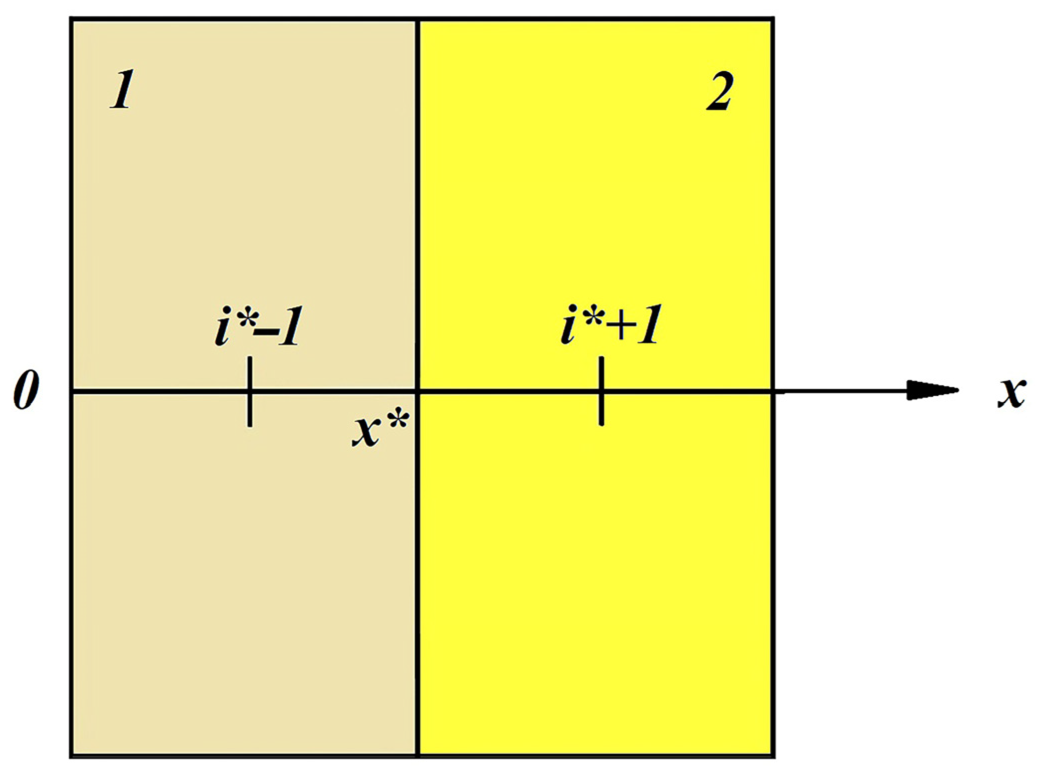
Under such conditions, we can limit ourselves to a one-dimensional nonstationary heat conductivity equation. That is, heat spreads only from the inner surface to the outer surface of the ladle lining. Temperature will only change in directions perpendicular to the boundary of the plate. If the Ox axis is directed as shown in
Figure 1, then the temperature in the directions of the Oy and Oz axes can be considered constant:
This simplification is confirmed, for example, by the authors in [
23]. The study proved that when the ladle is heated (in the temperature range from 50 to 900 °C), the temperature difference in the upper part of the ladle and at its bottom differs by no more than 1.5%.
Let us make the following assumptions:
- –
the thermal conductivity coefficient does not depend on temperature;
- –
there are no internal heat sources.
Taking into account the assumptions made, the differential Equation (3) will take the following form:
where L is the lining thickness, m.
Taking into account two layers of lining, the initial and boundary conditions can be written as follows:
We will solve this problem numerically using an implicit four-point difference scheme. The advantage of this scheme is its unconditional stability at arbitrary values of steps in coordinates and time. A type IV boundary condition is used to determine the coefficients at point x*, which is the point on the boundary of the lining layers.
We will calculate thermal stresses using the following formula, in accordance with the methodology given in [
24,
25,
26,
27,
28]:
where E—elastic modulus, kg/cm;
α—coefficient of thermal expansion, °C−1;
ν—Poisson’s ratio;
Tav—average temperature across the lining cross section, °C.
Ti—temperature at the point in question, °C.
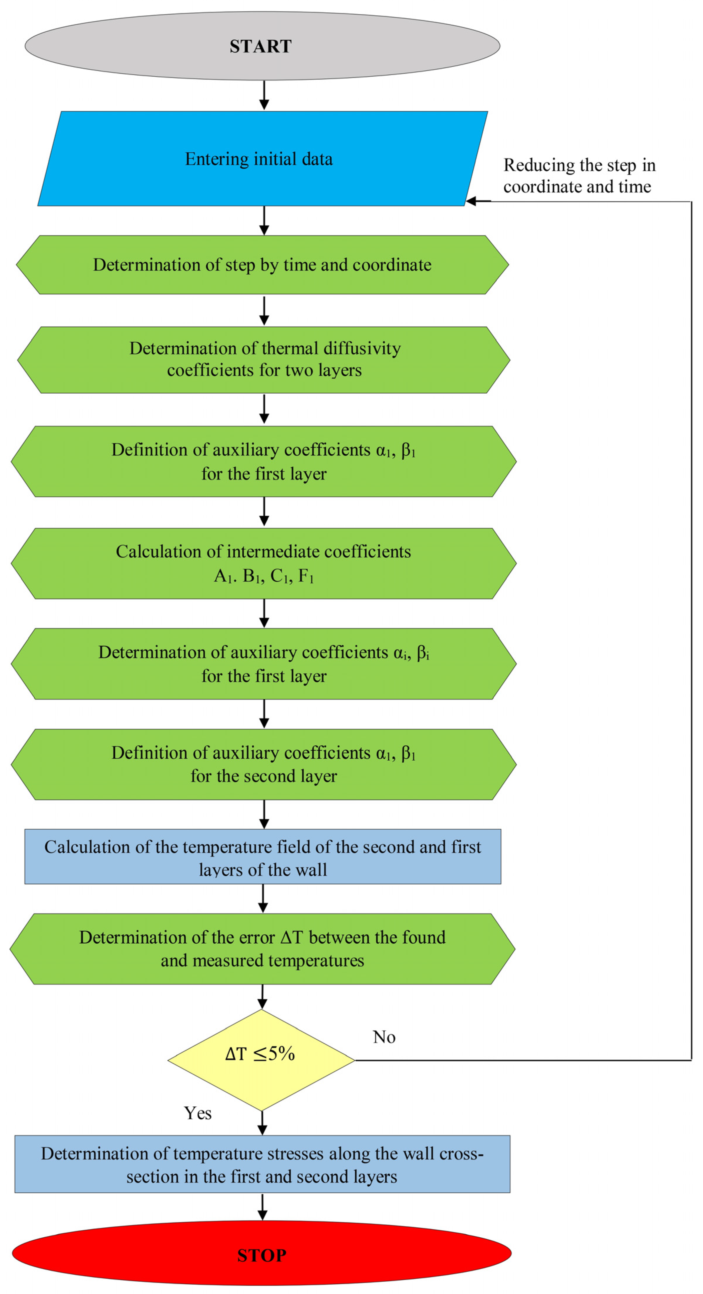
The solution to this problem, taking into account the boundary conditions, will be reduced to the following algorithm. At the first stage, we find the coefficients in the region 0 ≤ x ≤ x* using the characteristics of the first layer, and in the region x* ≤ x ≤ L using the characteristics of the second layer. At the second stage, using the backward tridiagonal matrix algorithm, we calculate the temperatures of the second and first layers. After determining the temperature fields, we find the average temperature value for each time step. Based on the data obtained, we calculate the thermal stresses in the second and first layers of the lining. The block diagram of the algorithm is shown in
Figure 2.
3. Results and Discussion
To solve the problem of studying the cooling of the casting ladle lining, temperature measurements were carried out in the zone of greatest wear of the lining. The zone of increased wear is the middle zone along the height of the ladle (between the fifth and seventh rows of lining). The temperatures of the outer surface of the casting ladle at a similar height were also measured. The measurements were carried out using an infrared pyrometer Kelvin Compact 1500/175.
During the operation of the casting ladle, a change occurs in the thermophysical and strength properties of the lining refractories. Research carried out in [
12] showed that the properties of the new refractory material differ from the properties of the material after three fuses. The ultimate tensile strength of chamotte refractories of the ShKU-32 brand after three fuses in the temperature range from 20 °C to 800 °C is lower than the ultimate tensile strength of the refractory material that has not been in operation. The change in the properties of these refractories can be divided into two stages. In the first stage (after one to two fuses), changes in the properties of refractory materials are insignificant (no more than 5%). The properties of a refractory that has not been in operation can be used for the calculations of this stage. The second stage is characterized by significant changes in the properties of refractories. Changes in the characteristics of refractories must be taken into account in the calculations at the second stage.
During the operation of casting ladles, repairs are carried out with partial replacement of the working layer of the lining. In this case, the lining is cooled to a temperature of 40 °C. At this temperature, repair works can be carried out in accordance with industrial safety requirements. Therefore, we will calculate temperature stresses for two options. In the first option, the calculation is carried out for refractories without significant changes in their properties (for the casting ladle lining after one to two fuses). In the second option, the calculation is carried out, taking into account changes in the properties of refractories (after three or more fuses).
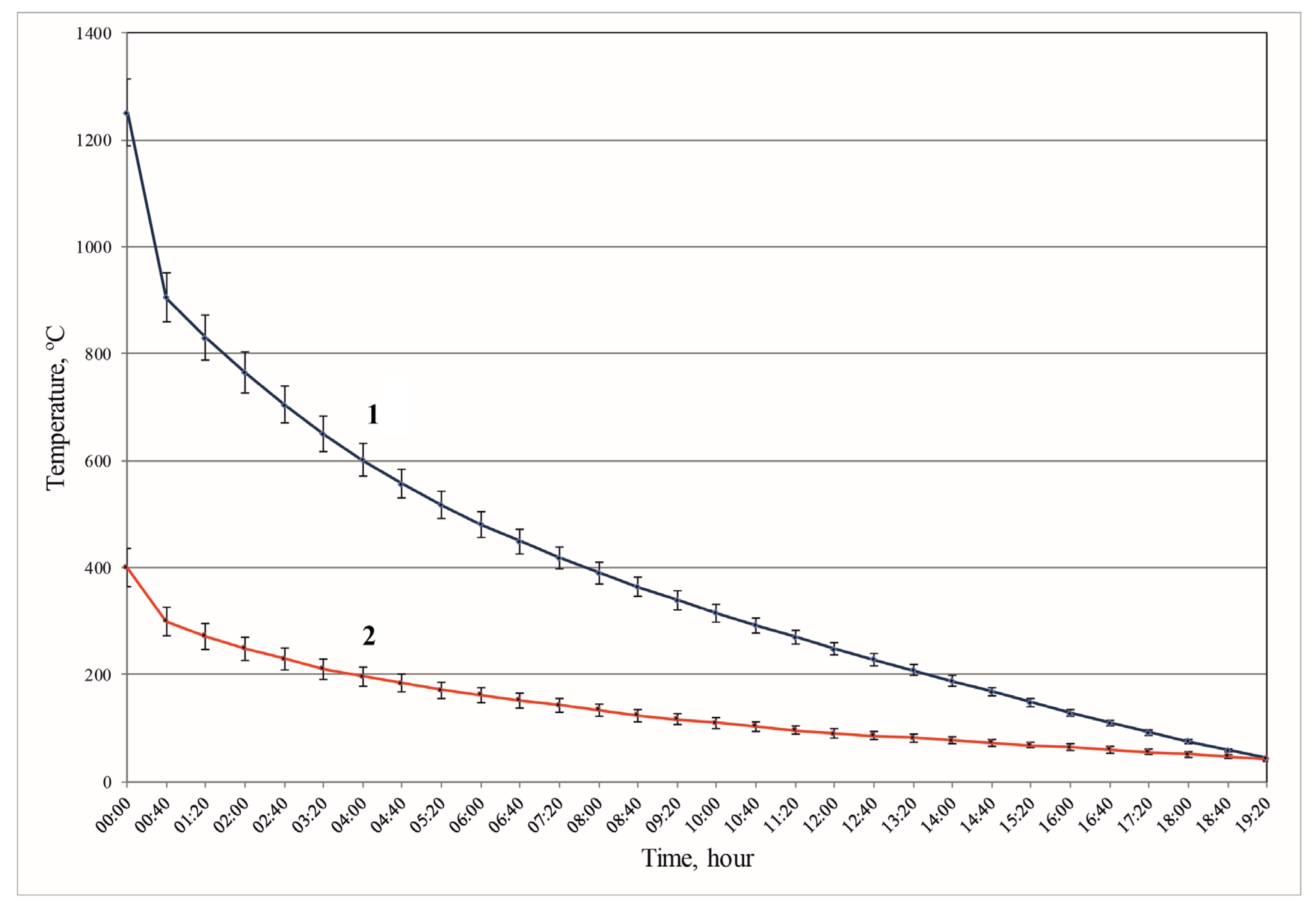
The changes in temperature in the inner and outer surfaces of the casting ladle lining during the cooling process are shown in
Figure 3.
The graph of changes in the temperature of the inner surface of the casting ladle lining can be divided into several periods. During the first period (initial 40 min of cooling), the temperature decreases from 1250 °C to 905 °C. This period is characterized by the highest rate of temperature decline of 517.5 °C/h.
Over the next four hours, the temperature decreases from 905 °C to 557 °C. The average rate of temperature decline was 87 °C/h. This exceeds the value of 60 °C/h that is recommended in the literature [
2,
5,
22].
This is followed by a period of decreasing the lining temperature from 557 °C to 39 °C with an average cooling rate of about 35 °C/h. At the last stage of cooling, attention should be paid to the following periods: a cooling period of four hours at a constant speed of 30 °C/h, a period of temperature reduction for 1 h 40 min at a constant rate of 27 °C/h, and the last period, which has a constant cooling rate of 24 °C/h.
Taking into account the relatively small thickness of the steel casing and the high value of the heat conductivity coefficient of steel, we will assume that the temperature on the outer surface of the ladle is equal to the temperature of the outer surface of the lining.
The process of reducing the temperature of the outer surface of the casting ladle lining can also be divided into several periods. During the first period, the temperature decreases from 400 °C to 300 °C. This period is characterized by the highest rate of temperature decrease of 150 °C/h.
This is followed by a period of 2 h 50 min, during which the temperature decreases from 300 °C to 206 °C. The average rate of temperature decrease was 33.15 °C/h. This is followed by a final period of temperature decrease from 206 °C to 40 °C at an average rate of about 10.38 °C/h.
The cooling of the casting ladle lining under natural convection conditions is very uneven. The temperature of the inner surface of the ladle decreases by 300 °C in the first 30 min. At the final stage of cooling, the temperature decreases by 300 °C within 10 h. Thus, the cooling rates of the inner surface of the lining at different stages differ by more than 20 times.
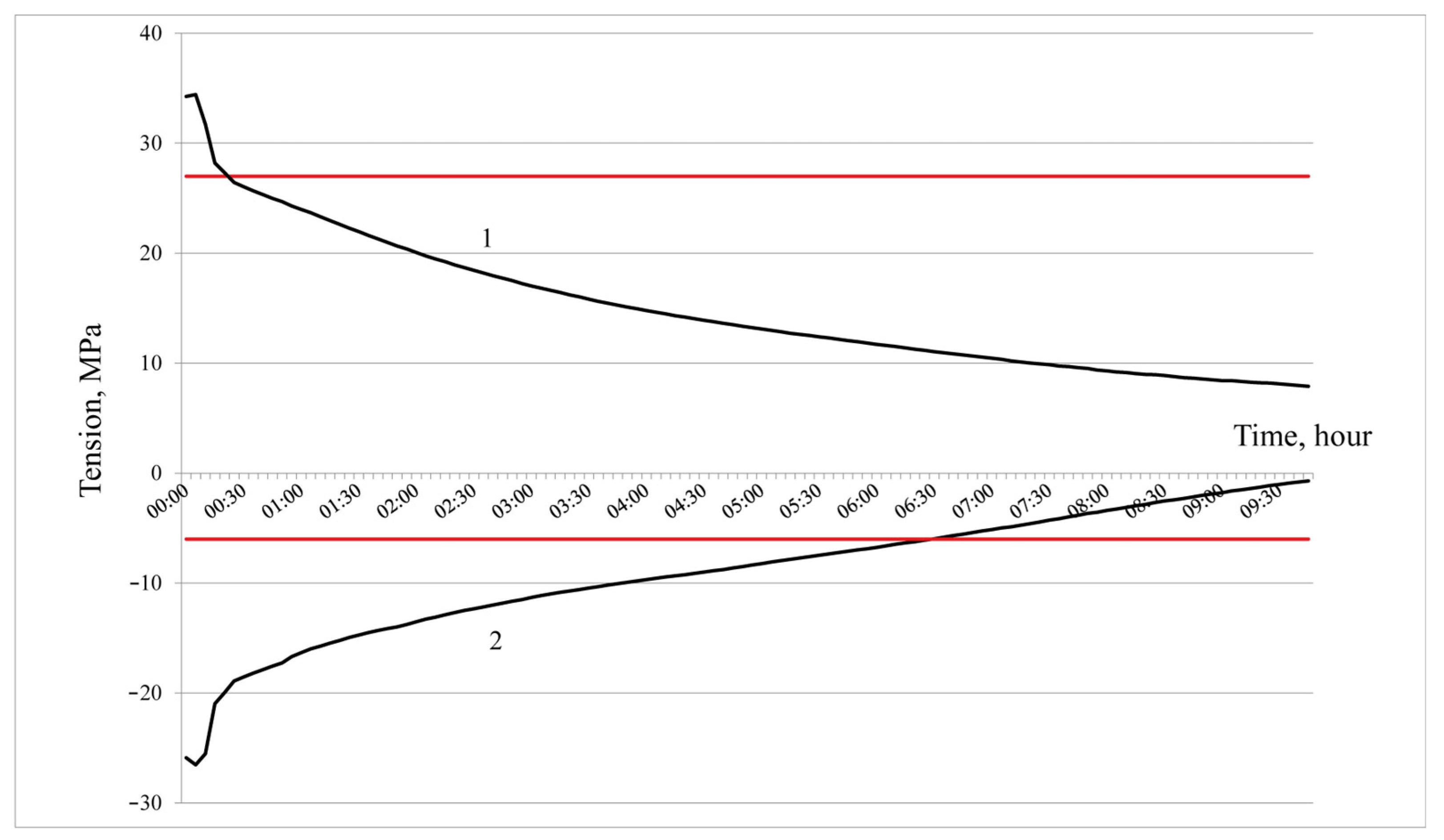
The results of calculations of thermal stresses for refractories that have not been in operation are presented in
Figure 4.
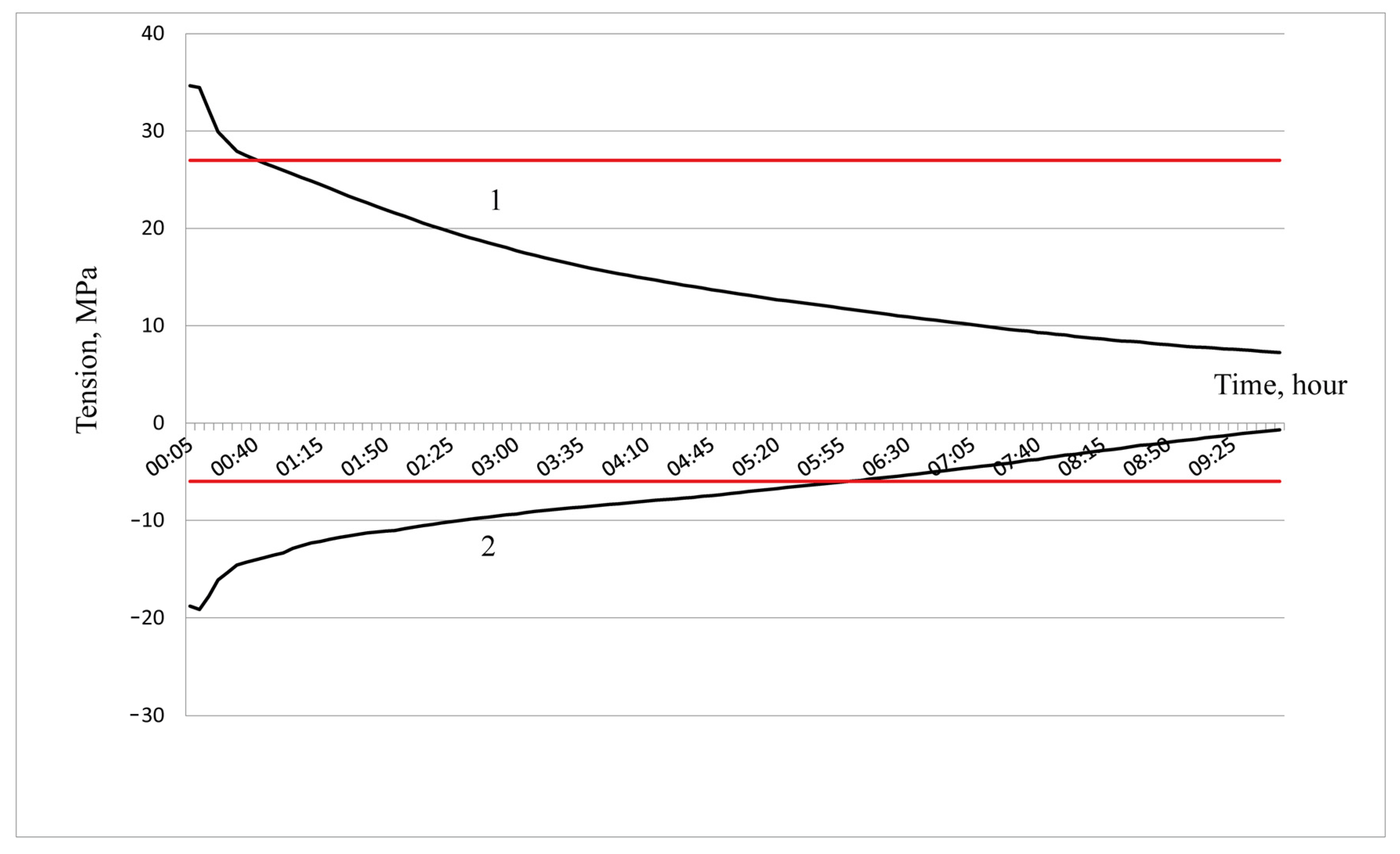
Line 1 shows the change in thermal compressive stresses during the cooling process. Line 2 shows the change in thermal tensile stresses during the cooling process. The red horizontal line with a value of 27 MPa is the ultimate compressive strength of the ShKU-32 refractory brick. The red horizontal line with a value of 6 MPa shows the ultimate tensile strength of the ShKU-32 refractory brick. Calculations were carried out for a time period of up to 9 h 45 min. Further cooling up to 19 h 30 min is characterized by a smooth decrease in thermal compressive and tensile stresses without exceeding the ultimate strength.
The maximum value of thermal compressive stress is 34.43 MPa, which is 1.27 times higher than the ultimate compressive strength of the ShKU-32 refractory brick. Thermal stresses exceed the ultimate compressive strength in the first 25 min of cooling.
The maximum value of thermal tensile stress is 26.52 MPa, which is 4.4 times higher than the ultimate tensile strength of the ShKU-32 refractory brick. Thermal stresses exceed ultimate tensile strength in the first 6 h 25 min of cooling.
The results of calculations of thermal stresses for refractories after three fuses are presented in
Figure 5. Line 1 shows the change in thermal compressive stresses, while line 2 shows the change in thermal tensile stresses during the cooling process of refractories. The calculation results are presented for a time period of up to 9 h 45 min. Further cooling up to 19 h 30 min is characterized by a smooth decrease in thermal compressive and tensile stresses without exceeding the ultimate strength. It has been established that the graphs have a similar shape to the graphs of thermal stresses for refractories that have not been in operation.
The maximum value of thermal compressive stress is 34.46 MPa, which is 1.28 times higher than the ultimate compressive strength of the ShKU-32 refractory brick. In this case, thermal compressive stresses exceed the ultimate compressive strength in the first 40 min of cooling.
The maximum value of thermal tensile stress is 19.12 MPa, which is 3.19 times higher than the ultimate tensile strength of the ShKU-32 refractory brick. Thermal tensile stresses exceed the ultimate tensile strength in the first 6 h of cooling.
Thermal stresses exceeding the ultimate strength correspond to high rates of temperature decrease (
Figure 3).
The duration of exposure to thermal tensile stresses exceeding the ultimate strength is significantly longer than the duration of exposure to compressive stress. This is explained by the nature of the temperature change, namely its decrease. During sudden cooling, the temperature difference between the surface of the outer lining layer and the environment will be greater than the temperature difference between the surface of the inner lining layer and the environment.
After the first 40 min of cooling, within 4 h, the temperature decreases at an average rate of 87 °C/h (which exceeds the recommended in the literature value of 60 °C/h). This period is reflected in
Figure 5 in the form of a curve, in which the thermal stress values exceed the ultimate tensile strength of the refractory.
An analysis of the cooling of the casting ladle lining showed that the existing schedules of cooling by natural convection are characterized by significant unevenness and high rates of temperature decrease. The cooling rates of the inner surface of the lining at different stages differ by more than 20 times. The maximum rate of temperature decrease is 517.5 °C/h.
High rates of temperature decrease lead to significant thermal stresses in the lining. For a refractory that has not been in use, the maximum value of thermal compressive stress exceeds the ultimate compressive strength by 1.27 times. The maximum value of thermal tensile stress exceeds the ultimate tensile strength by 4.4 times.
For refractories after three melts, the maximum value of thermal compressive stress exceeds the ultimate compressive strength by 1.28 times. The maximum value of thermal tensile stress exceeds the ultimate tensile strength by 3.19 times.
