Review

Smart AC-DC Coupled Hybrid Railway Microgrids Integrated with Renewable Energy Sources: Current and Next Generation Architectures

by
Hamed Jafari Kaleybar
1,
Hossein Hafezi
2,*,
Morris Brenna
1 and
Roberto Sebastiano Faranda
1
1
Energy Department, Politecnico di Milano, 20156 Milan, Italy
2
Faculty of Information Technology and Communication Sciences, Tampere University, 33100 Tampere, Finland
*
Author to whom correspondence should be addressed.
Energies 2024, 17(5), 1179; https://doi.org/10.3390/en17051179
Submission received: 28 December 2023 / Revised: 19 February 2024 / Accepted: 28 February 2024 / Published: 1 March 2024

Abstract

:
In recent years, there has been increasing interest in integrating the smart grid concept into railway networks, which has been driven by the need to enhance energy efficiency and reduce air pollution in such energy-intensive systems. Consequently, experts have actively sought innovative solutions with which to tackle these challenges. One promising strategy involves integrating renewable energy sources (RESs), energy storage systems (ESSs), and electric vehicle charging stations (EVCSs) into current electric railway systems (ERSs). This study begins by examining the concept of implementing smart grids in railway systems through bibliometric analysis. It then delves into the realization of a hybrid railway microgrid (H-RMG) designed to enhance power flow capacities, improve energy efficiency, and address power quality issues in traditional AC railway networks. This paper introduces various future AC–DC-coupled hybrid railway microgrid (ADH-RMG) architectures centered around a shared DC bus acting as a DC hub for upgrading conventional AC railway systems utilizing interfacing static converters. Through an exploration of different possible ADH-RMG configurations, this research aims to offer valuable insights and a roadmap for the modernization and reconstruction of existing railway networks using smart grid technologies. The integration of RESs and EV charging infrastructures within the ADH-RMG concept presents a promising pathway toward establishing more sustainable and environmentally friendly railway systems.

1. Introduction

In recent years, there has been increasing focus on incorporating the smart grid concept into railway networks, aiming to boost energy efficiency and reduce air pollution in these high-energy-consuming systems. As a result, experts have been exploring innovative solutions to integrate renewable energy sources, energy storage systems, and electric vehicle (EV) charging stations with present railway networks [1,2].
The execution of the smart grid implementation marks a transformative leap in Electric Railway Systems (ERSs), promising unprecedented capabilities and opportunities. This paradigm shift envisions a future ERS architecture that starkly diverges from its present state. The basic configurations of DC and AC railway microgrids, complemented by the direct integration of distributed energy sources to these systems, are presented for the first time in [2]. Within the domain of DC railway microgrids, two distinctive architectures emerged: low-voltage DC (LVDC) and medium-voltage DC (MVDC), each offering unique features. Simultaneously, AC and hybrid railway microgrids are classified, encompassing interface frequency converters (IFC), railway power flow controllers (RPFC), and co-phase structures. The comprehensive comparison encompasses potential challenges, benefits, and hurdles inherent to each structure, considering the seamless integration of distributed energy resources (DERs), energy storage systems (ESSs), and EV charging infrastructure in [3,4].
The deployment of any of these proposed microgrid structures to revamp and rejuvenate existing railway networks constitutes a pivotal stride towards embracing Smart Grid (SG) technologies within the railway sector and for grid–customer interaction [5,6]. However, AC transformer-based traction substations (TSS) have become prevalent due to advancements in power technologies and electric motors. The global adoption of AC ERS is extensive in regional and high-speed railways, featuring two supplying configurations: 16.67/25 Hz–15 kV and 50/60 Hz–25 kV. These systems can be categorized based on the overhead catenary type, distinguishing between uncomplicated 1 × 15/25 kV and autotransformer-dependent 2 × 15/25 kV systems [7,8]. However, AC ERSs encounter difficulties related to power quality (PQ) concerns, elevated expenses, and diminished efficiency [9,10,11]. Notably, problems like voltage/current unbalance, voltage drops, power factor issues, and various harmonic distortions are significant concerns in AC ERSs [12]. The integration of smart grid technologies, particularly the incorporation of RES, may exacerbate these issues in so-called AC-coupled railway microgrids (AC-RMG) [2]. Despite the DC-coupled railway microgrids (DC-RMG), which have been widely studied for energy management systems [13,14,15], power flow optimization [16,17], and integration configurations [18,19], AC-RMGs have not received much attention from experts and researchers, which originates from the limitations and inherent problems of this type of network.
In recognition of the limitations of AC ERSs, researchers have been investigating MVDC-based railway supply systems as an alternative, offering several advantages and potential solutions to address the challenges faced by AC ERSs [20,21,22]. The most suitable voltage range for MVDC ERSs is recognized to be 7.5–9 kV, enhancing the potential and advantages of applying smart grid concepts in MVDC ERSs [2]. Accordingly, for nascent projects and forthcoming railway networks, the MVDC railway micro-grid (MVDC-RMG) architecture emerges as a promising pathway, amalgamating the advantages inherent to both AC-RMGs and LVDC-RMGs [23,24]. This multifaceted approach not only promises to revolutionize the energy landscape of railway systems but also stands as a testament to the forward-thinking endeavors driving the evolution of sustainable and efficient transportation networks worldwide. However, it is essential to note that converting existing AC ERSs to MVDC systems requires substantial equipment modifications and substitutions, resulting in considerable costs.
Motivated by the mentioned issues, this study introduces the concept of hybrid railway microgrids (H-RMG) with a shared DC hub as a next-generation railway supply system. Accordingly, the main contributions of this study are:
  • Introduction of the concept of hybrid railway microgrids (H-RMG) as an innovative solution for enhancing existing AC electric railway systems (AC ERSs).
  • Proposing AC–DC-coupled hybrid RMG (ADH-RMG) as a key component of H-RMG, highlighting its potential to mitigate power quality (PQ) issues through interfacing static converters.
  • Presentation of diverse ADH-RMG architectures specifically designed for integration with existing AC ERSs, offering a range of solutions for modernizing conventional railway networks.
  • Comprehensive analysis of the key features, advantages, and drawbacks of various ADH-RMG models to provide a thorough understanding of their applicability.
  • Conducting an extensive model comparison, contributing to the existing literature by offering valuable insights into the performance and suitability of different ADH-RMG architectures for railway power supply systems.
The paper is organized into distinct segments, with the Section 2 focusing on bibliometric analysis. Section 3 delves into the principles and concepts of various RMGs, encompassing AC, DC, and hybrid variations. The Section 4 explores diverse architectures of AC–DC-coupled hybrid RMGs, while Section 5 elucidates existing applications and installations. Moving on, Section 6 scrutinizes and contrasts the performance, advantages, and drawbacks of each configuration. This paper concludes in Section 7, summarizing the key findings and insights presented throughout.

2. Review Methodology and Bibliometric Analysis

As a bibliometric analysis, a survey of keywords was carried out to track the development of smart grid-based railway networks and elucidate the fundamental research directions. In this context, the keyword survey was employed to recognize and classify various research directions related to the integration of smart grid technology into railway systems. To accomplish this, the primary source for publications was the Scopus Web of Science database, and a comprehensive set of articles was obtained through a Boolean search. A total of 620 documents published between 2015 and 2022 were included in the search, with specific constraints on language (English) and research areas (engineering, energy, environmental science, computer science). The analytical tool used to extract key terms and research directions was the VOS Viewer 1.6.19.0 software.
The resulting cluster map, illustrated in Figure 1a, indicates that the keywords can be organized into three primary clusters, representing distinct research topics associated with the implementation of smart grid technology in railway systems. Each circle’s size in the visual representation corresponds to the frequency of the chosen keyword, with lines and distances indicating relationships within the same group. The clusters are categorized and can be identified by their content, encompassing energy, IoT, and communication. The analysis uncovered the strongest connections between the “energy” cluster and the core topic “rail systems,” marking it as the primary focus of the paper. Key terms within this cluster included “railroad transportation”, “railroad”, “energy storage”, “energy utilization”, and “regenerative braking energy.” Other clusters, such as “IoT”, “5g mobile communication”, and “wireless communication” contained keywords outside the paper’s scope.
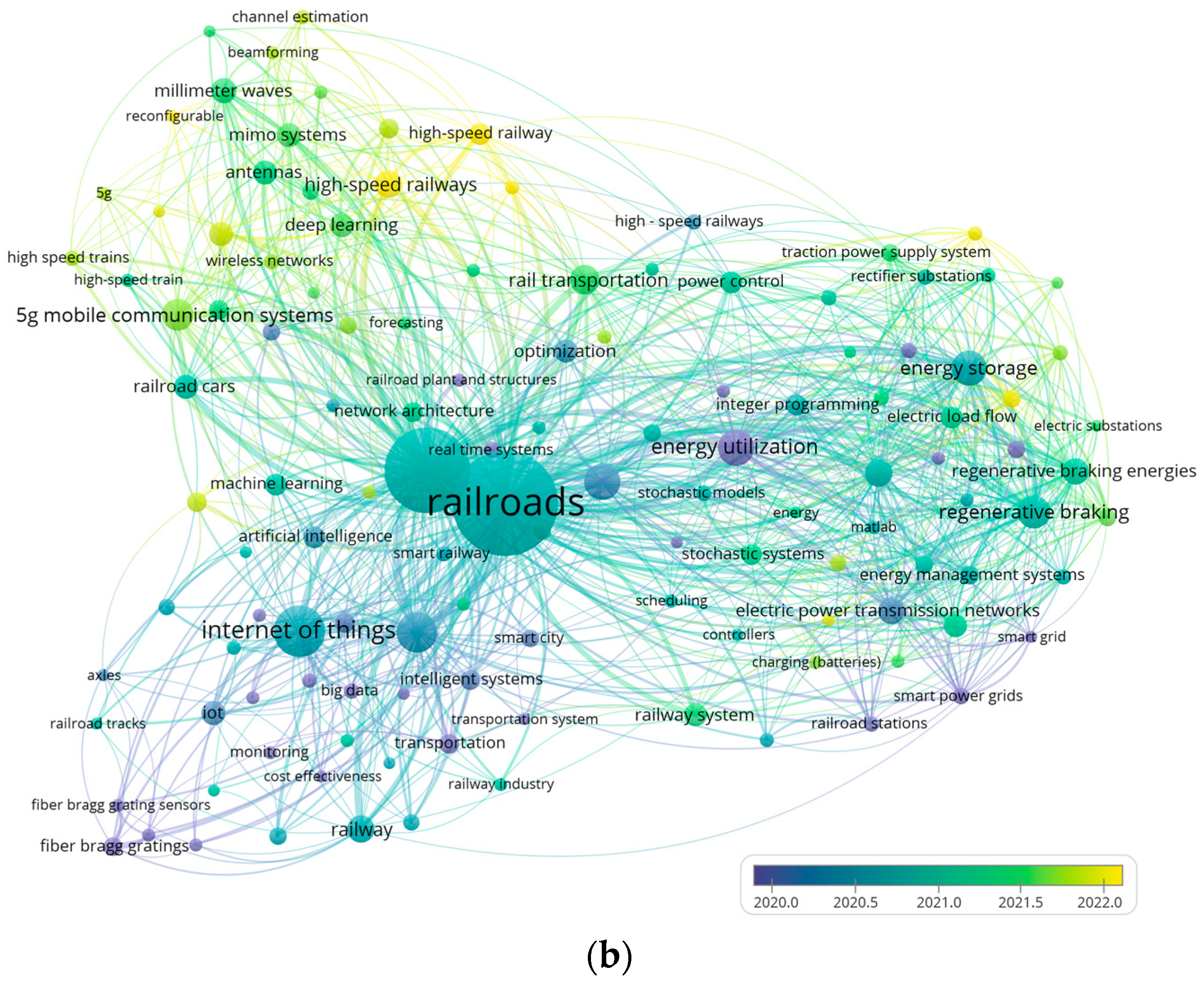
The time overlay visualization in Figure 1b demonstrates that keywords related to “energy” and “IoT” clusters, including others, have gained increasing significance since 2020, with notable attention in recent years. The “communication” cluster, on the other hand, emerged as a widespread trend starting in 2021.
Bibliometric analysis indicates that the exploration of smart grid implementation in railway systems, along with each mentioned aspect and cluster, is likely to expand in the future. The research stream and the identified gap in the energy cluster lead to subsequent sections presenting an overview of different architectures of smart H-RMGs applicable to existing AC railway supplying systems, elucidating their applications along with their respective advantages and disadvantages.

3. Concepts and Principles of Different RMGs

3.1. Background of ERSs

The evolution of railway electrification systems has been influenced by factors like population growth, increased demand for high-powered transport, and various country-specific policies. Initially, transformer-based systems predominated, utilizing a direct current (DC) supply to power DC motors. These systems employed three-phase multiple pulse rectifiers to supply energy to locomotives. DC ERSs utilize a continuous flow of electrical charge in a single direction. The lower end of this range, around 600 volts, is commonly employed in urban transit networks and light rail systems, providing efficient and reliable power for short- to medium-distance travel. On the higher end, at 3000 volts, DC systems are capable of supporting more demanding applications, such as higher-speed intercity trains. These higher voltages allow for increased power delivery, facilitating faster acceleration and deceleration of trains. Additionally, 3000V DC systems are known for their relative efficiency in power transmission, making them an attractive choice for various railway electrification projects around the world.
As power technology advanced, AC transformer-based ERSs gained popularity, with the 1 × 25 kV simple and back-feeder configurations being early choices. However, these systems faced challenges, such as voltage and current imbalances due to single-phase feeding, as well as issues like low power factor, harmonics, transient problems, electromagnetic interference (EMI), and telecommunication interface complications related to return currents. Efforts to reduce return currents and mitigate EMI led to the introduction of the booster-transformer-based 1 × 25 kV ERS. Nevertheless, this approach had drawbacks, including potential damage to the overhead contact system (OCS), due to large arcing, and reduced train operating speeds. In response to these issues, the autotransformer-based 2 × 25 kV ERS was implemented, featuring fewer inductive and telecommunication interfaces, reduced voltage drops, and minimized arcing problems.
These AC ERSs ensure efficient and sustainable transportation by delivering the required electrical energy to locomotives. Among the commonly used voltage levels are 11, 15, and 25 kV. The 11 kV AC system strikes a balance between power efficiency and safety. This standard is widely employed in urban and regional rail networks. It provides sufficient power for both commuters and certain express services. Its moderate voltage allows for effective long-distance power transmission without compromising safety.
Moving up the voltage spectrum, the 15 kV AC system is recognized for its efficiency in power distribution. It is well-suited for high-speed rail networks where trains require substantial power to maintain impressive speeds. This voltage level enables trains to achieve higher velocities with greater efficiency, making it a cornerstone in the electrification of high-speed rail systems worldwide.
At the higher end of the scale, the 25 kV AC system is a crucial standard in electrified railway networks, especially in regions with extensive high-speed rail networks and long-distance train services. It efficiently transmits power over extended distances, ensuring that high-speed trains can maintain their velocity over long stretches of track. The 25 kV AC standard is known for minimizing energy losses during transportation and enhancing the overall capacity and efficiency of the rail network.
These various voltage standards reflect the dynamic nature of railway electrification, catering to different needs in diverse rail networks around the world. The choice of voltage depends on factors such as the type of service, required speeds, and the specific demands of the rail network in question. Figure 2 demonstrates the distribution of each of the mentioned supplying systems in Europe.
A further advancement came in the form of the co-phase system, designed to decrease arcing problems and improve train speeds by reducing the number of neutral sections and insulating areas in China [25,26].
In the realm of AC industrial frequency-based ERS, certain countries like Germany, Norway, Sweden, Austria, and Switzerland adopted the 16.67 Hz ERS utilizing rotating frequency converters (RFC) [27]. However, this system faced stability and transient challenges due to the synchronous coupling of motors and generators.

3.2. Concept of Railway Microgrids

A microgrid is a localized, self-contained power system that can operate independently or in conjunction with the main electrical grid. It comprises various components, including renewable energy sources (such as solar panels and wind turbines), energy storage systems (such as batteries, super-capacitors, or flywheels) [28], power electronics, and control systems. These elements work in tandem to generate, store, and distribute electrical energy efficiently within the railway network. However, due to high power loads of ERSs and traction substations, operating independently, without being connected to the main electrical grid as a standalone mode, seems to be an almost impossible situation for railway systems. The standalone mode concept can be justified in multimodal-based trains in non-electrified or partially electrified lines [29,30]. In non-electrified or partially electrified railway lines, the implementation of a standalone mode for railway microgrids emerges as a transformative solution. These lines, often found in remote or underserved regions, face challenges in providing a reliable and sustainable power source for trains. By harnessing renewable energy sources and advanced storage systems, a standalone microgrid can function as an independent power hub. This allows trains to operate seamlessly, even in areas where connecting to the main electrical grid is impractical or economically unfeasible.
The standalone mode (islanding) enables these microgrids to function as self-sustained energy ecosystems, eliminating the need for diesel generators and reducing dependency on conventional fossil fuels. Solar panels and wind turbines become pivotal components, harvesting energy from the environment and storing it in advanced battery systems. This stored energy can be released when trains are in operation, ensuring a continuous and reliable power supply. As a result, the standalone mode not only enhances energy efficiency but also significantly reduces greenhouse gas emissions, contributing to a cleaner and more sustainable rail network.
Accordingly, in discussing the implementation of smart grid or microgrid technology in fully electrified railway systems as the main purpose of this paper, our focus shifts primarily towards enhancing the auxiliary supply of these systems. This entails the integration of renewable energy sources, along with the seamless interconnection of these sources with ESS and EVCIs.
Other main challenges in smart railway microgrids are control strategies and energy management systems, which should be employed to manage the flow of energy within the railway microgrid. These could involve smart grid technologies, automation, and control algorithms to balance energy generation, consumption, and storage. This topic has been addressed in [31,32] in detail and, therefore, will not be addressed in this paper. Overall, regarding the found gap in the literature, this paper will mainly discuss the architectures of RMG’s principles of RESs and distributed generation integration with these systems.

3.3. Principles and Main Configurations of RMGs

Railway microgrids, shaped by the specific characteristics and diverse supply configurations previously examined, can be broadly categorized into three main classes: DC RMGs, AC RMGs, and Hybrid RMGs. Each classification embodies distinct approaches to power distribution and management within railway systems.

3.3.1. DC Railway Microgrids

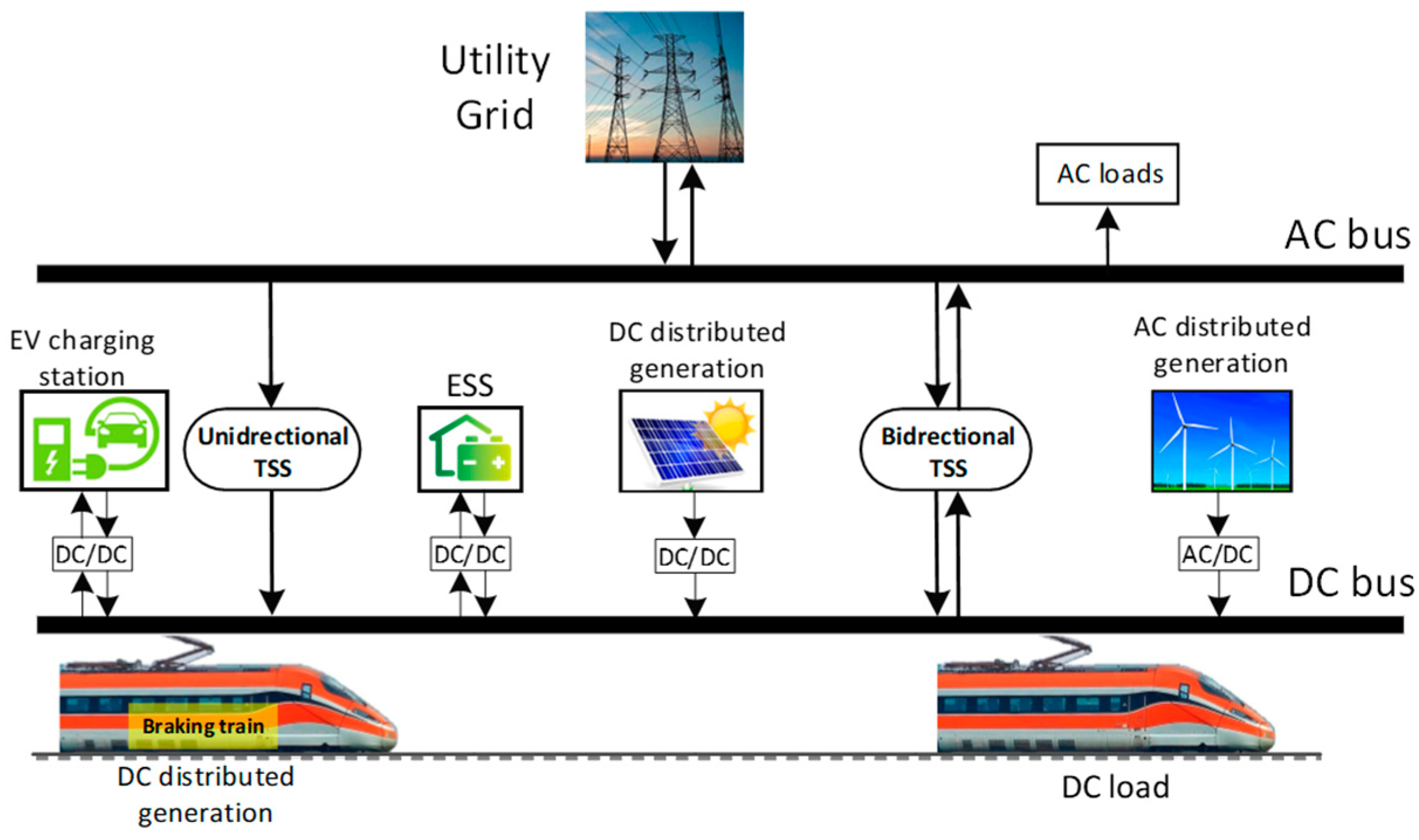
The DC ERSs, characterized by lower power demand, are predominantly concentrated in densely populated metropolitan and urban areas. These systems, owing to their adeptness at harnessing regenerative braking energy (RBE) and their structural compatibility with integrated DERs, have evolved into sophisticated smart DC microgrids. Many DERs operate on DC systems, such as photovoltaic arrays and energy storage systems, or incorporate a DC component, as is the case with wind generators, facilitating seamless integration. Figure 3 illustrates the overarching concept of a DC-RMG. Through the amalgamation of DC ERS and DERs within a shared DC link, an energy hub is established. This hub effectively aggregates electricity generated by various sources, including generators and braking trains, and channels it towards connected loads such as trains, internal substation loads, and electric vehicle charging infrastructure, or feeds it back into the grid using bidirectional substations. DC-RMG holds significant potential for energy conservation through optimized power flow management, while simultaneously enhancing power quality and overall efficiency. Depending on the voltage and power requirements dictated by the existing and evolving structures of DC railway systems, two primary categories of DC-RMG emerge for further study: low-voltage DC-RMGS and medium-voltage DC-RMGs.
The low-voltage DC-RMG can be created for urban rail networks, trams, subways, and light rail systems with low-to-medium power demand. It operates at voltages ranging from 600 to 3000 V, allowing for efficient energy usage. The key innovation of low voltage DC-RMG lies in its RBE capability, which enables the recovery of surplus energy during braking, leading to reported energy savings of 20% to 40%. Conventional TSS are typically unidirectional, necessitating the dissipation of excess energy. In contrast, bidirectional TSS can employ IGBT-based converters to allow for bidirectional energy flow, facilitating the injection of RBE energy back into the grid. The system components include AC–DC substations, catenary/third rail systems, renewable generators, energy storage systems, and charging infrastructure for EVs. By integrating charging infrastructure directly into the DC section, DC-RMG promotes sustainable mobility and reduces reliance on the AC mains, making it suitable for mid and fast EVCIs.
However, low-voltage DC-RMG faces limitations in train power and capacity due to high currents in the overhead catenary/third rail system. As a result, high-power suburban and high-speed railway systems typically rely on high-voltage AC systems. However, these AC systems come with power quality challenges, including inductive voltage drop, low power factor, and harmonics. To address these issues, experts have explored the potential of a new MVDC electrification system for ERSs. MVDC offers high-power capabilities, enabling the direct connection of DERs like wind farms and large-scale photovoltaic systems without the need for AC conversion [21,33]. Moreover, MVDC allows for the implementation of fast and ultrafast charging stations for electric vehicles, reducing strain on the AC mains. The optimal voltage range for MVDC ERS is identified as 7.5–24 kV, chosen based on infrastructure evaluation and regional considerations [2]. The MVDC system can also integrate with low-voltage DC-RMG through dedicated DC/DC converters, providing flexibility and enhanced capabilities. The surplus components in MV DC-RMG, compared to LVDC-RMG, include renewable high-power generators and advanced charging infrastructures for EVs, accommodating ultrafast charging stations and upcoming megachargers for trucks and tractor-trailers. While MVDC-RMG offers benefits for both AC and DC systems, it also presents challenges in management, control strategies, cost of power electronics, and the availability of appropriate disconnection and protection devices. Overall, MVDC-RMG holds significant potential for advancing the efficiency and capabilities of ERSs.

3.3.2. AC Railway Microgrids

The MVDC-RMG is still in the early stages of development, whereas AC ERSs are already established and widely used for suburban and high-speed railways. However, the integration of microgrid concepts in AC ERSs, particularly from a hardware perspective, has not received much attention due to certain limitations. Most energy-saving solutions and microgrid/smart-grid-based procedures for AC ERSs focus on software optimizations related to traffic, speed profiles, and timetables.
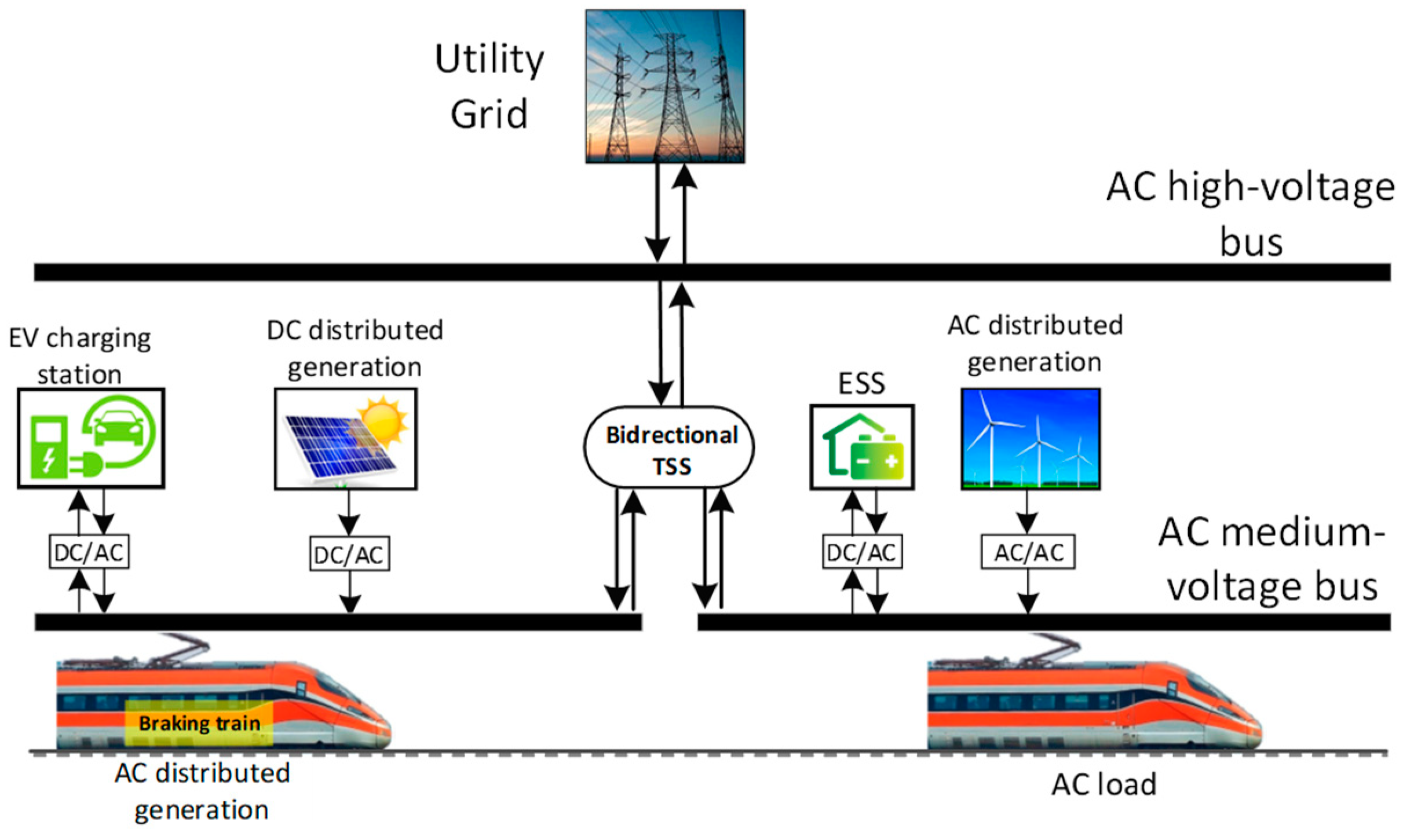
In AC ERSs, the utilization of RBE by other trains is less common due to isolated sections, but it is possible to feed back the RBE to the main grid. Implementing microgrid technologies in AC ERSs requires consideration of power quality issues, especially declining system inertia. As shown in Figure 4, AC-RMG employs DC/AC converters to connect DERs and other elements to the supply system.
AC ERSs commonly use a 25 kV–50 Hz catenary as the supply system. Power quality issues in AC ERSs include voltage imbalance due to single-phase supply, necessitating high short circuit power to reduce imbalance, which increases costs. Voltage drops, reactive power fluctuations, and harmonic problems further challenge AC systems. Realizing the microgrid concept in this context can exacerbate these issues if not carefully addressed. The AC-RMG architecture involves traction transformer-based substations with the ability to feed back RBE to the main grid and a catenary overhead system for power delivery. Neutral sections are used to isolate sections that are supplied by different voltages, with their placement determined by the type of transformer system used [34,35].
The medium voltage AC busbar, acting as an energy hub, can be established at either the substation level or along the railway line. However, direct connections in AC-RMG limit power flow capacity, making it more suitable for low-power generators. High-density ESSs can be applied, and categorized as on-board, off-board, and way-side ESS. While way-side ESS can help regulate catenary voltage drops, it comes with drawbacks like power losses and implementation costs in densely populated areas. In terms of EVCIs, AC-RMG may be less suitable for megachargers and ultrafast charging systems due to its low power flow capacity. Rectification-based converters in charging infrastructures may also introduce harmonic resonances in the overhead catenary system.

3.3.3. Hybrid AC–DC Railway Microgrids

To enhance power flow capabilities and overcome power quality limitations within the AC-RMG architecture, a hybrid RMG structure is a promising solution. Meanwhile, most DGs are in DC mode generation which makes it more suitable to be connected to a DC bus. Accordingly, the hybrid RMG utilizes an interfacing DC bus to streamline suitable connections between various elements.
The term “Hybrid AC–DC railway microgrid” denotes a microgrid that incorporates both AC and DC power sources as well as AC and DC loads in railway systems. The specific structure of a hybrid AC–DC RMG is determined by how the sources and loads are integrated into the system, and how the AC and DC buses are configured. Three main classifications can be proposed as AC-coupled, DC-coupled, and AC–DC-coupled.
In AC-coupled hybrid RMGs, diverse DGs and ESSs are connected to a shared AC bus through their respective interfacing converters. Conversely, in DC-coupled hybrid RMGs, DGs, and ESSs are linked to a collective DC bus, and an interconnecting converter facilitates the connection between the DC and AC buses. Finally, in ADH-RMG, DGs and ESSs are connected to both DC and AC buses, with these buses interconnected by an interlinking converter. This paper mainly deals with these types of architectures, and the next section will provide an overview of these RMG structures and offer real-world implementation examples for each.
Depending on specific design objectives and priorities, the interconnecting converters and structures can be further categorized into different configurations, which will be explained in detail in the next sections.

4. AC–DC-Coupled Hybrid RMGs (ADH-RMGs)

AC–DC Hybrid Railway Microgrid (ADH-RMGs) refers to a microgrid that incorporates both AC and DC power sources as well as AC and DC loads.
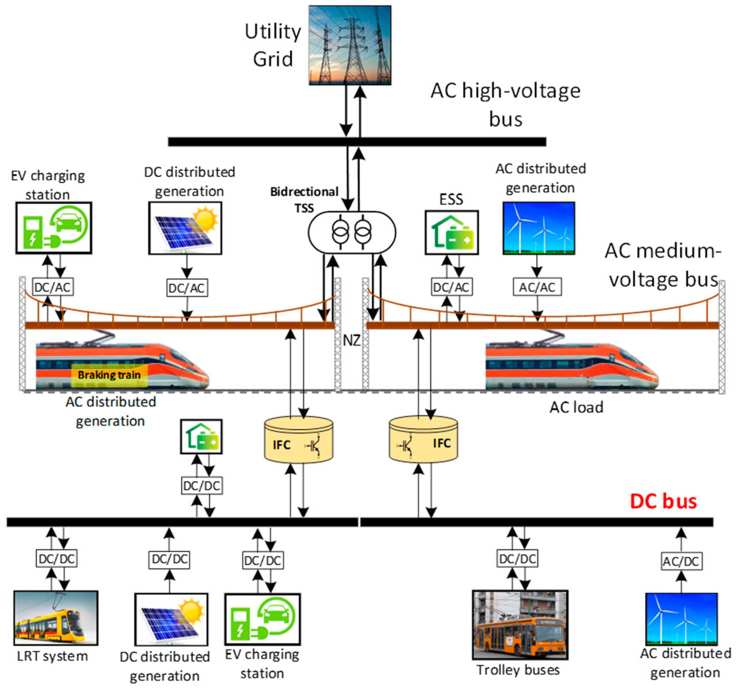
The typical configuration of an AC–DC-coupled hybrid railway microgrid is depicted in Figure 5. In this illustration, both the DC and AC buses incorporate DGs, ESSs, and other low-voltage DC transportation systems interconnected by interfacing converters. Unlike the DC-RMGs, this ADH-RMG integrates DGs and ESSs onto both the AC and DC buses, requiring more intricate coordination for voltage and power control between the DC and AC subsystems. Similarly, parallel interfacing converters are essential for linking the AC and DC buses, enhancing capacity and reliability, mirroring the setup in a DC-coupled microgrid. Generally, this structure is a good solution to be chosen when the primary power sources encompass both DC and AC power.
This approach enhances overall efficiency and lowers system costs by reducing the number of necessary power converters, streamlining the connection of sources and loads to the AC and DC buses with minimal power conversion requirements. Given these advantages, ADH-RMGs are poised to be highly promising microgrid configurations in the foreseeable future for railway systems.
However, while the concept of an ADH-RMGs holds great promise, it warrants in-depth study and investigation, particularly in terms of energy and power conversion. The interfacing converters and their control for such a configuration must account for voltage (and frequency) regulation on both the DC and AC buses, as well as ensure power balance within the DC and AC subsystems. This calls for careful consideration and comprehensive analysis in order to effectively implement and manage ADH-RMGs.
AC ERSs serve as well-established and extensively employed power supply systems for both regional and high-speed railways throughout most of Europe. These systems are characterized by their connection configurations and supply arrangements and are categorized into three primary types: dual-phase, co-phase, and advanced co-phase systems. The study of ADH-RMG architectures primarily revolves around traditional dual-phase systems and relatively new co-phase systems. The main structures together with the interfacing converters will be addressed in the next sections.

4.1. ADH-RMG in Traditional Dual-Phase Supplying Systems

The dual-phase ERS functions with two autonomous traction arms, each acquiring power from separate phases. In this setup, both sides of the Traction Substation (TSS) draw power from distinct phases of a low-frequency traction transformer. This transformer is linked to the high-voltage or medium-voltage three-phase grid on the primary side [36,37]. Consequently, the right and left segments remain segregated from one another, facilitated by a designated neutral zone (NZ) area.
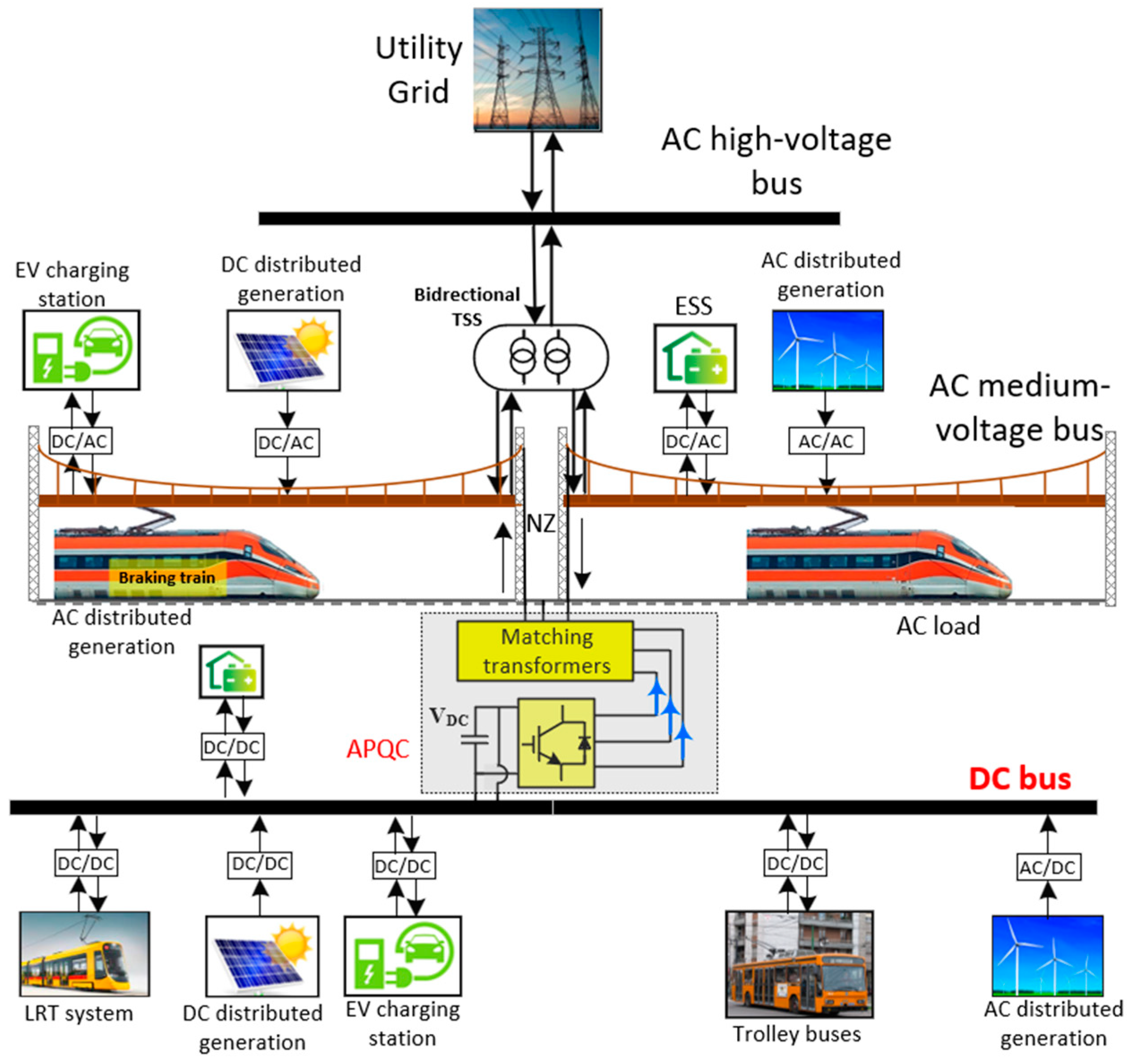
Depending on factors such as power capacity, design preferences, and specific objectives, the architectural configurations of ADH-RMGs within dual-phase ERSs can be categorized into three fundamental designs: those focused on an interface IFC, an RPFC, or an active power quality compensator (APQC).

4.1.1. IFC-Based ADH-RMGs

This architectural design incorporates a unified DC bus to facilitate and enhance the capacity for bidirectional power flow in components employing interfacing converters. To further elaborate on this architecture, it is important to note that the joint DC bus plays a pivotal role in seamlessly integrating various elements equipped with interfacing converters. This integration not only enhances bidirectional power flow capabilities but also contributes to the overall efficiency and reliability of the system. The arrangement of IFC-based ADH-RMGs with IFC is illustrated in Figure 6. With advancements in electronic power control and semiconductors, robust voltage-source converters such as MMCs [38,39] and cascaded converters can be directly utilized as IFC, enabling the potential for sending RBE back to the upstream grid. Furthermore, the inclusion of a step-down low-frequency transformer (LFT) allows for the use of conventional medium-power AC–DC converters. Overall, these configurations with high power capabilities enable the immediate linking of high-capacity RESs and ultra-fast EV DC charging systems, eliminating the requirement for voltage level adjustments. However, a significant drawback of this architecture lies in the complexity of controlling the IFC during high-load scenarios [40]. Additionally, it is unable to address system imbalances in the primary side of TSS due to the single-phase supply of sections.
While the benefits of the joint DC bus are substantial, it is worth noting that the costs associated with establishing it along the entire line can be considerable. Therefore, it is advisable to strategically implement this infrastructure, focusing primarily on critical locations such as substations, where its impact would be most significant. Meanwhile, it is important to consider the issue of NZ in this architectural configuration. These NZs, which isolate two sections of TPSS supplied by different voltage phases, can cause some radiated EMI issues [41] and therefore decrease the utilization speed of trains due to the contacts of pantograph and OCS.

4.1.2. RPFC-Based ADH-RMGs

To address the primary PQ challenges associated with AC single-phase ERS and enhance the capacity and efficiency of the ADH-RMG, employing RPFC-based TSSs presents a promising solution. In this configuration, the RPFC-based ADH-RMG incorporates two converters linked by a shared DC-link capacitor, which are connected to the catenary on either side of the TSS through buck LFT [42]. Figure 7 illustrates the typical structure of an RPFC-based ADH-RMGs.
Thanks to the inclusion of the DC-link capacitor in the RPFC, the DC bus provides a straightforward means of integrating DESs and EV charging infrastructure. Additionally, the high capability of RPFC enables simultaneous compensation of the main PQ issues within this system, even those introduced after integration. Moreover, the reciprocal back-to-back converters facilitate regenerative braking energy flow between sections and trains.
Despite the notable advantages offered by this architecture, it is important to note that the power flow range is restricted due to challenges associated with controlling the DC-link voltage and maintaining DC bus stability. Consequently, the RPFC-based ADH-RMGs may not be the optimal solution for interconnecting high-power DERs and EVCIs. This limitation can be addressed by implementing high-capacity MMC-based RPFCs [43,44]. However, it is worth mentioning that, in this configuration, they are directly connected to TSS sections without the need for a step-down transformer. As a result, the joint DC bus voltage in multi-level RPFCs is higher, necessitating the use of interface converters to connect to the joint DC bus.
From an infrastructure upgrade perspective, the establishment of RPFC-based ADH-RMGs is feasible primarily in TSS or sub-sectioning posts, as RPFC connects two sections with differing voltages. Additionally, it is important to consider the issue of NZs in this architectural configuration.
One benefit of utilizing this ADH-RMG is that the power routing equipment does not impact the original configuration of the traditional TPSS. Moreover, it can easily accommodate various types of traction transformers. Consequently, this approach is suitable for upgrading existing TPSSs at a relatively low cost. Furthermore, in the event of a failure in the power routing equipment, the power supply to the system remains uninterrupted, ensuring the system’s reliability.

4.1.3. APQC-Based ADH-RMGs

This architectural configuration introduces a unified DC bus system, incorporating an APQC to effectively augment bidirectional power flow capabilities in various elements. The APQC structure, derived from RPFC, employs a single voltage source converter equipped with three legs operating in two phases [45]. This setup allows for a streamlined connection between the joint DC busbar and the ERS through the use of balanced transformers, referred to as matching transformers. These transformers play a crucial role in aligning the electrical characteristics between the DC bus and the ERS, ensuring seamless integration [46].
However, it is essential to acknowledge that the control and management of an APQC-based ADH-RMG can pose additional complexities. This arises from the inherent challenges associated with achieving precise voltage balancing in a three-wire, two-phase system as shown in Figure 8. Engineers and operators must implement advanced control strategies to address these intricacies effectively.
Despite the benefits of this architecture, it is important to note that certain challenges persist. For instance, the issue of NZ management remains relevant, necessitating careful attention during the design and operation phases. Additionally, the architecture may have limitations in terms of power flow capacity, particularly in scenarios where high power demands are prevalent.

4.2. ADH-RMG in Co-Phase Supplying Systems

In the preceding section, it was demonstrated that all delineated architectures of ADH-RMGs for dual-phase ERSs exhibit NZ issues. The presence of NZ concerns, coupled with the discontinuity of the overhead catenary system, can give rise to significant problems, including arcing and mechanical challenges. Moreover, these issues can complicate the seamless transfer of energy between different sections for power balancing. In addressing these challenges, co-phase ERSs emerge as a promising structural solution [47].
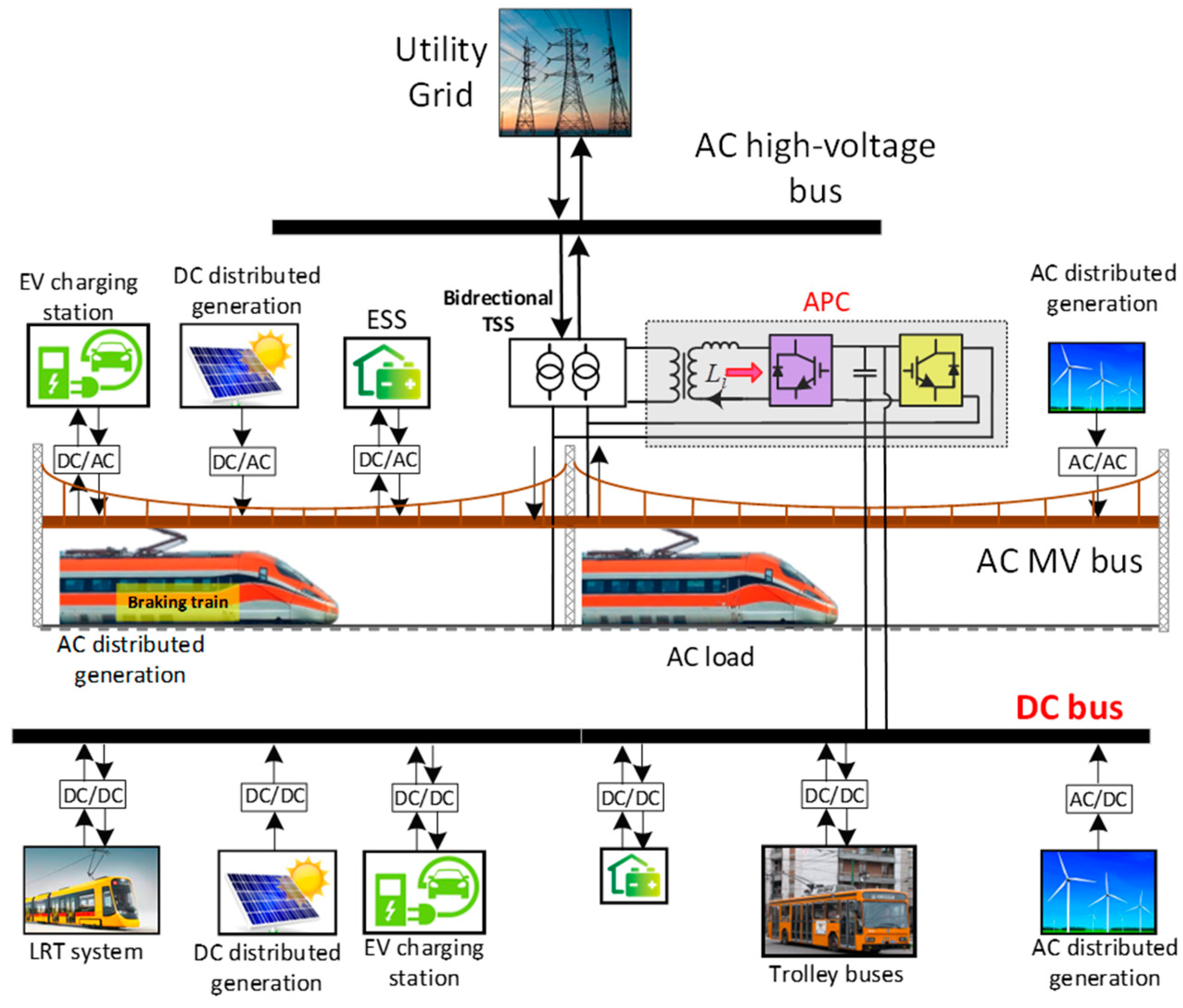
Illustrated in Figure 9, co-phase ERSs consist of an LFT-based balanced transformer with a back-to-back converter connected to one arm. The configurations of ADH-RMGs in co-phase systems can vary based on the chosen converter topology. Two primary configurations are notable: the APC-based ADH-RMGs and the SHC&SAC-based ADH-RMGs. It is essential to emphasize that the implementation of co-phase ADH-RMGs allows for the elimination of neutral sections in the TSS position, although not in the subsection post position. The integrated co-phase ADH-RMG fails to achieve full separation between the traction network and the three-phase utility grid. This leads to the unavoidable influence of the traction load on the utility grid. Consequently, the number of NZs can be effectively reduced by half. This structural modification contributes to mitigating the challenges associated with NZs, arcing, and mechanical considerations, while simultaneously facilitating more efficient energy transfer between sections for improved power balance.

4.2.1. APC-Based ADH-RMGs

In this particular form of ADH-RMG, an active power conditioner (APC) operates as the compensating interface. It is connected to a balanced or matching transformer on one end and the distinctive overhead catenary system on the opposite end, enabling the provision of power to trains [48]. The comprehensive structure of the ADH-RMG employing an APC in co-phase systems is illustrated in Figure 9. This configuration is akin to the RPFC-based ADH-RMG but with a reduced number of NZs.
The presence of a single-phase power flow in this setup exacerbates imbalances on the primary side of the TSS. To streamline the integration of DERs and EVCIs, these components are connected to the shared DC link through a DC bus hub. Notably, in this structure, both the DC bus bar and its associated elements are interconnected through the APC to the AC network and AC ERSs at the same time. Consequently, a coordinated power flow control system is imperative for managing both the AC and DC sections effectively. This design modification not only reduces the number of NZs but also calls for a more intricate power flow control mechanism to ensure seamless operation across the interconnected AC and DC sections.

4.2.2. SHC&SAC-Based ADH-RMGs

Leveraging the benefits of the series hybrid converter and shunt active converter (SHC&SAC), which has been introduced to enhance PQ issues in co-phase ERSs, an alternative structure for ADH-RMG is illustrated in Figure 10. This particular design sets itself apart from other architectures by featuring non-joint DC links for the two converters, allowing for more independent operation and integration.
Unlike its counterparts, this configuration capitalizes on the added capacitor in the SHC, resulting in a decreased power rating for the converter [49]. DERs and EVCIs can be independently connected to the DC links, offering a level of autonomy in their operation. As a result, the key advantages of the SHC&SAC-based ADH-RMG include a relatively straightforward structure, independent functionality, and a conventional control system. It is worth noting, however, that the application of a multilevel SHC&SAC to enhance power flow capability could incur significant costs.

4.3. ADH-RMG in Advanced Co-Phase Supplying Systems

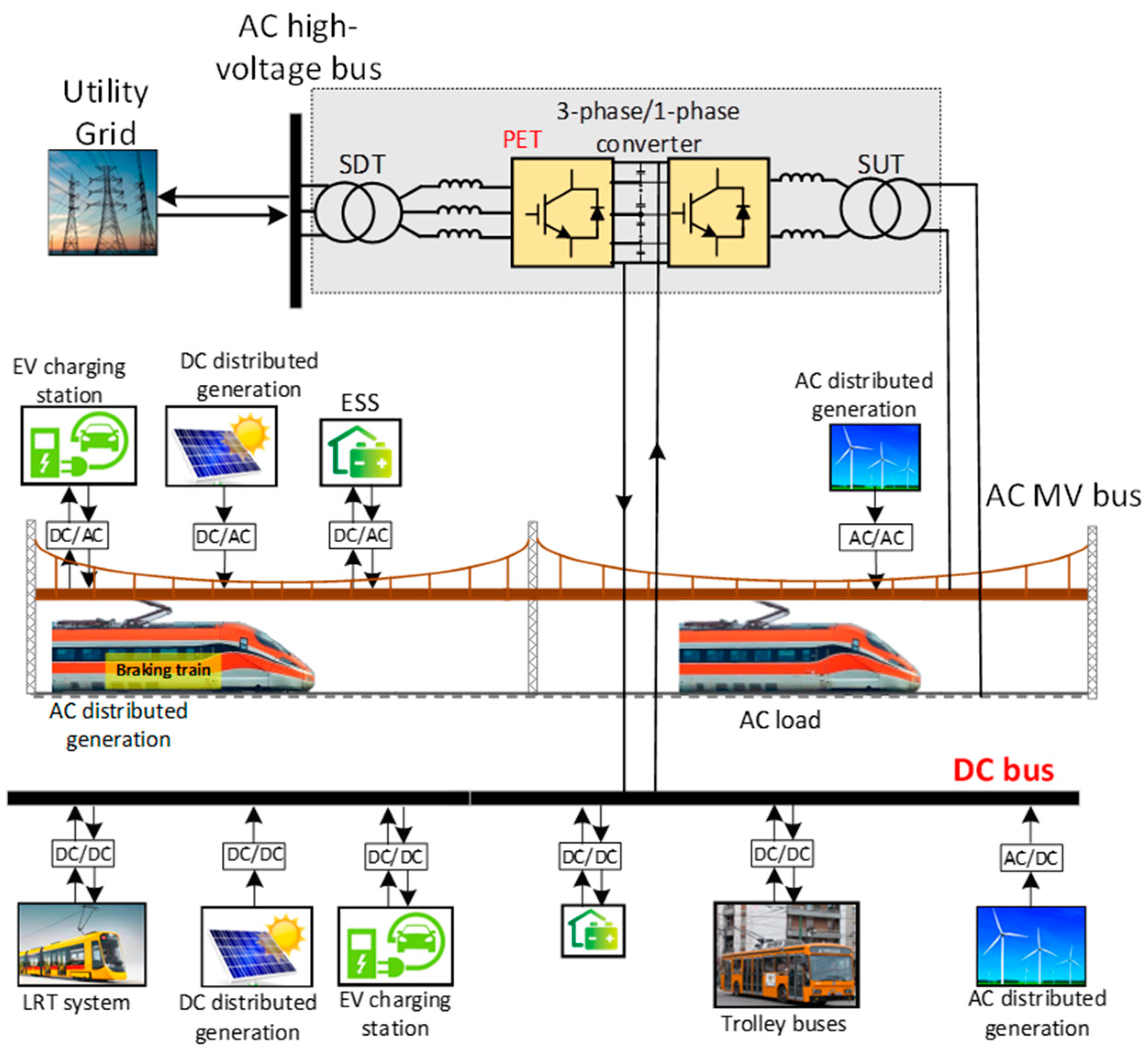
To achieve uninterrupted connectivity throughout the entire overhead catenary system and eliminate NZ and insolation sections, advanced co-phase ERSs are introduced in [50,51]. Figure 11 depicts this innovative design, utilizing three-phase to single-phase converters for power supply. Various configurations can be considered for the conversion process, such as direct AC/AC or indirect AC/DC/AC methods. The former requires the utilization of power electronics converters based on MMCs with multiple modules and switches, primarily due to significant voltage disparities between the primary and secondary sides. However, this approach, which is suitable for MVDC ERSs, falls beyond the scope of this paper. Therefore, the focus of this paper centers on the more promising solution of indirect AC/DC/AC conversion for energizing the overhead catenary system.
The catenary is energized through TPSSs utilizing the power electronic transformer (PET). This PET consists of a three-phase rectifier and a single-phase inverter, allowing for the control of both the output voltage domain and phase, aligning them with the dedicated voltage of the entire railway system.
On the high-voltage primary side, this configuration utilizes a high-capacity step-down transformer to decrease the voltage rating of switches. Depending on the specific design goals and power flow needs, a step-down transformer might also be integrated on the low-voltage secondary side. The converters on the left side operate as rectifiers, facilitating the transfer of power from the utility to the DC-link capacitor and storing it as DC power. Subsequently, the right VSC acts as an inverter, converting DC power to the OCS based on 15/25 kV and 16.67/50 Hz. This configuration, also known as static frequency converters (SFC) [52], features bi-directional IGBTs, allowing the transfer of regenerative braking energy from the catenary to the utility grid.
With this structure, locomotives receive power from multiple TPSSs simultaneously, thereby augmenting the power supply capacity in contrast to the unilateral power supply mode. The PETs play a crucial role in decoupling the traction network from the utility grid, effectively mitigating the adverse impact of the traction load on the utility grid.
DERs and EVCIs can be connected to the DC links, similar to other architectures. The operational system of the SFC plays a pivotal role in intelligently furnishing power to the overhead catenary while adhering to PQ standards for tackling harmonic issues and reactive power concurrently. Additionally, the three-phase provision from the SFC works to mitigate imbalance conditions within this ADH-RMG framework. A major benefit lies in the elimination of the NZ owing to the distinctive supply route, resulting in a substantial improvement in the speed of train utilization. Nevertheless, it is crucial to acknowledge that the substantial LFT in this design may result in diminished compensation capacity, an increased switching frequency, higher power loss, and the need for a generously sized AC filter. Moreover, the initial capital investment for high-capacity and high-voltage PETs is noteworthy.

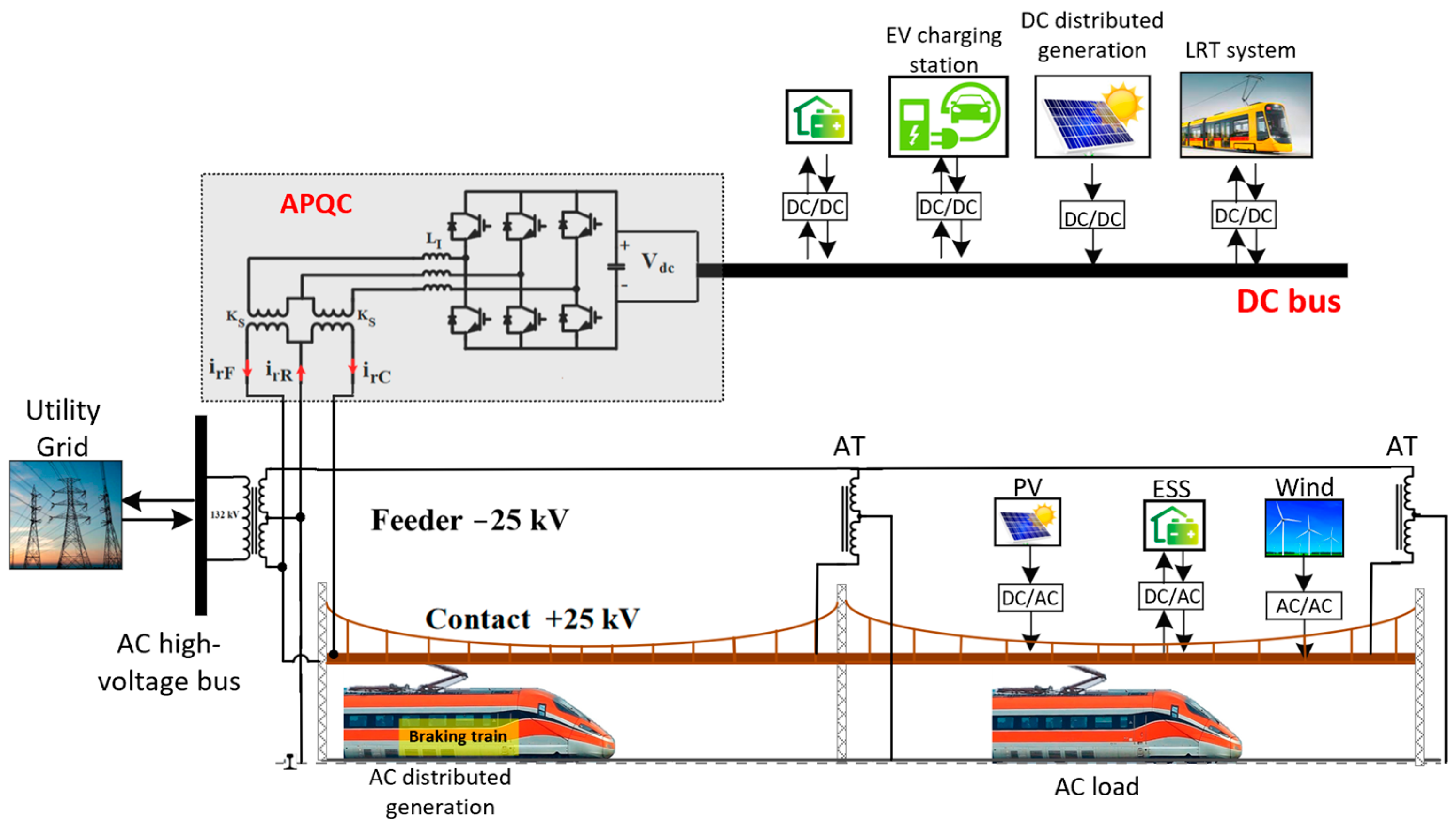
4.4. APQC-Based ADH-RMG in 2 × 25 kV

The 2 × 25 kV railway system represents a dual overhead electrification configuration for rail transport, featuring two parallel 25 kV lines. In contrast to the more common 1 × 25 kV system, the dual-line configuration offers several distinct advantages. Firstly, it allows for increased power distribution capacity, accommodating higher train speeds and heavier loads [53]. The redundancy provided by two independent lines enhances system reliability and minimizes the risk of service disruptions due to faults or maintenance. Additionally, the 2 × 25 kV system reduces power losses over longer distances, contributing to improved energy efficiency [54]. The dual-line setup also facilitates a more balanced power supply to different sections of the railway network. While the 1 × 25 kV system remains prevalent, particularly in regions with lower power demands, the 2 × 25 kV configuration is increasingly favored in high-speed rail networks and areas with greater electricity consumption, offering a robust solution for efficient and reliable railway electrification. However, the main purpose of establishing such systems is to compensate EMIs and decrease rail currents, especially with signaling systems.
In this architecture of ADH-RMG, an active power quality compensator (APQC) serves as the interface compensator. It is linked to the auto-transformer by step-down transformers [55]. The overall architecture of the APC-based ADH-RMG in 2 × 25 kV is depicted in Figure 12. Nevertheless, it is crucial to recognize that overseeing the control and management of APQC-based ADH-RMGs can introduce added complexities. These complexities stem from the inherent difficulties associated with achieving precise voltage balancing in a three-wire, two-phase system while maintaining a fixed phase shift between the contact wire and feeder wire. To effectively address these intricacies, engineers and operators must implement advanced control strategies. Despite the advantages offered by this architecture, it is noteworthy that certain challenges persist. For example, the management of NZ remains a pertinent issue, requiring meticulous attention during both the design and operational phases. Additionally, the architecture may exhibit limitations in terms of power flow capacity, especially in situations where high power demands are prevalent.

5. Applications and Existing Direct Installation of RESs into ERSs

Among various forms of renewable energy generation, solar power stands out as the most promising option for rail transportation due to its flexible accessibility through the installation of solar panels in available spaces. This approach is gaining traction among rail operators, who are utilizing their own spaces to install solar panels and generate solar power [56,57,58,59,60].
The implementation of photovoltaic panels in railway systems offers versatile configurations, each catering to specific advantages. One prevalent approach involves establishing a photovoltaic power plant alongside the railway track, utilizing the expansive linear space to install solar panels. This configuration maximizes exposure to sunlight and can contribute significantly to the overall energy needs of the railway network. Additionally, integrating solar panels on the rooftops of stations/tunnels/depots presents an efficient use of available space, generating renewable energy to power station facilities and contributing to the local grid. Another innovative strategy involves installing solar panels on the rooftops of trains, transforming moving platforms into mobile solar generators. This on-train configuration can harness solar energy during transit, potentially reducing dependency on external power sources. Moreover, the combination of these configurations, alongside potential alternatives like solar-integrated noise barriers or solar pavements within railway depots, showcases the adaptability of PV technology in enhancing sustainability across various facets of railway systems.
In the realm of rail transportation in China, notable installations include the 2008 introduction of the primary rooftop photovoltaic system at Beijing South railway station, covering approximately 14,000 m2 with a capacity of 220 kWp. In 2013, Hangzhou East railway station installed a 10.0 MWp rooftop photovoltaic generation using crystalline silicon solar panels, producing about 10.4 GWh of electricity in a year. Similar installations have been observed in railway depots in various countries, such as the 2.4 MW photovoltaic generation at Shaling depot in 2016, 1.0 MW PV generation at Xizhaotong depot in 2016, and 5.0 MW PV generation at Yuzhu depot in 2018.
In Japan, the East Japan Railway Company (JR-East) has embraced environmental conservation activities, including the installation of a 453 kW solar power generation above the platform for tracks 9 and 10 at Tokyo Station in 2011. In 2014, a 1050 kW solar power generation was implemented inside Keiyo Rolling Stock Center, contributing to cost reduction and powering their railways.
Belgium features a groundbreaking initiative where 16,000 solar panels on the roof of a 3.6 km rail tunnel generate 3300 MWh of electricity annually. This not only powers rail infrastructures but also electric trains, resulting in an estimated annual reduction of 2400 tons of carbon emissions.
Australia’s Byron Bay Railway Company introduced an onboard solar energy-powered electric train fitted with curved solar panels on the roofs, providing up to 6.5 kW of photovoltaic power to charge a 77 kWh battery storage system. Additionally, station rooftops host a large array of solar panels capable of producing up to 30 kW, powering operating trains via catenary lines in the ERSs.
Table 1 summarizes these applications based on the installed topology and locations.
Although great steps have been taken towards the integration of RESs and ERSs, the majority of these RES generations are not connected to a shared bus or expected to supply the trains in traction mode. They are considered to be supplied by auxiliary loads of stations or trains.
Some of the various existing electric railway supplying systems around the world that can be developed regarding ADH-RMG in the future are summarized in Table 2. As shown in this table, dual-phase ADH-RMG architecture with less penetration of DESs has found notable applications in various locations, showcasing its versatility in different railway systems. Notable implementations include the Shinkansen line in Japan, where the integration of IFC/RPFC/APQC technology has contributed to the efficiency of the high-speed rail network. In China, the Hunan Shimen and Shanghai Nanxiang traction substations have adopted dual-phase technology, enhancing the performance of their railway systems. Additionally, the technology has been applied to the Datong–Qinhuangdao and Lanzhou–Lianyungang railway lines, demonstrating its widespread use in the Chinese rail network. Beyond Asia, Aurizon, an Australian rail operator, has also embraced the dual-phase architecture for improved traction power supply.
Co-phase and advanced co-phase ADH-RMG architectures with less penetration of DESs have been successfully employed in various locations, showcasing their adaptability and effectiveness. In China, the Meishan and Shayu traction substations, along with the Wenzhou Intercity Railway S1 and Guangzhou Metro Line 18, have implemented co-phase technology (APC/SHC&SAC), optimizing the power supply for efficient rail operations. Moreover, the advanced co-phase architecture with indirect LFT-based SFC/MMC-based PET has been applied in global locations, including the Nuremberg Railway in Germany, Tokaido Shinkansen in Japan, Queensland railway in Australia, and the Beijing Daxing International Airport line in China. These implementations highlight the international relevance of advanced co-phase ADH-RMG technology, addressing the intricacies of power supply in diverse railway environments.

6. Discussion and Comparison

The implementation of resilient TPSS featuring DC, AC, or hybrid ADH-RMGs presents a noteworthy approach for advancing the next generation of railway TPSS. The incorporation of RMGs harnesses the inherent solar and wind resources along rail routes to meet escalating power demands while promoting greater use of renewable energy and reducing carbon emissions. Collaborating with ESSs, RMGs enhance flexibility and controllability.
RMGs, by leveraging their ability to provide flexible and harmonic currents, address utility grid imbalances, harmonics, and voltage fluctuations, thereby elevating power quality. Furthermore, the integration of DERs and ESSs within RMGs allows for the supply of electricity to the traction network, covering locomotive and station loads. In extreme grid scenarios, RMGs can autonomously island themselves, ensuring uninterrupted power supply to locomotives. They play a pivotal role in creating resilient TPSSs for railways, offering flexible and reliable power with improved quality and heightened resilience.
Examining the implementation of the smart grid concept in ERSs as the forthcoming generation supply system is the focus of this investigation. This study explores various architectures of smart electric railway grids, such as AC-RMGs, DC-RMGs, and H-RMGs, highlighting their advantages and disadvantages. According to the most applicable features of ADH-RMGs, their different architectures are categorized as dual-phase, co-phase, and advanced co-phase systems, each equipped with dedicated interference converters. Table 3 provides a comprehensive overview, classifying and comparing the different types of ADH-RMGs. Implementing these ADH-RMGs becomes a crucial step in renewing and reconstructing existing TPSSs, steering the evolution toward resilient TPSSs in the railway sector.
When considering utilization speed, especially in applications dedicated to high-speed trains, advanced co-phase ADH-RMGs emerge as the optimal choice due to the absence of NZ. Meanwhile, 2 × 25 kV ADH-RMGs, due to the higher voltage supply and longer TPSS distance, are known to be a promising solution for high-speed railways. However, from a perspective of power quality and power flow capability, dual-phase grids based on RPFC and co-phase grids demonstrate comparable performance to the more expensive advanced co-phase systems.
In the context of regenerative braking energy utilization, the bidirectional nature of RPFC-based and PET-based traction stations in AC railway electrification enables RBE feedback to the grid. However, for IFC-based ADH-RMGs and SHC&SAC-based configurations, there are limitations due to the separated DC link, and the RBE can not completely be transferred from one section to the other one.
Cost considerations are closely tied to power capability, and MMC-based SFC and PET-based co-phase ADH-RMGs are high-cost configurations. Accordingly, these architectures are only suggested for the new lines which are under construction. Meanwhile, to control the grid-connected converters in these architectures, they can operate in three main control modes: grid-following, some grid-forming, or all grid-forming. Grid-following converters synchronize with the grid’s frequency and voltage for a stable connection. Some grid-forming converters can establish their grid parameters, enabling autonomous or microgrid operation. All grid-forming converters have full control over grid parameters, offering autonomy and resilience in varying grid conditions. The selection of control mode depends on the application’s requirements and the desired level of grid interaction or independence [98,99,100].
In general, implementing any of the aforementioned ADH-RMG architectures for the rejuvenation and enhancement of the current AC ERSs represents a significant stride toward realizing a smart grid within the railway sector and making one step forward to the next generation of TSSs. Nevertheless, for new and under-construction TPSS and projects based on future technologies, a thorough investigation and performance analysis of advanced co-phase grids compared to MVDC-RMGs would be prudent. Nevertheless, challenges persist for MVDC-RMGs, including the higher cost of power module complexities associated with multiple sub-grids and the absence of appropriate DC disconnectors and protection devices. Anticipated technological progress and cost reductions in the future position MVDC-RMGs as the most promising approach for railway electrification, ensuring greater integration of renewable energy, heightened energy efficiency, simplified architecture, and enhanced resilience. However, for existing networks with the objectives of upgrading and augmenting energy efficiency, the dual-phase and co-phase architectures stand out as optimal solutions. These configurations offer a blend of the advantages inherent in both DC and AC ERSs.

7. Conclusions and Future Trends

Unlike other sectors in the power systems domain, electric railway systems have lagged behind in integrating renewable energy sources and implementing the smart grid concept. This paper introduces possible future AC–DC-coupled hybrid railway microgrid architectures, all centered around a shared DC bus serving as a hub for upgrading conventional AC railway systems taking advantage of interfacing static converters. Accordingly, first, the concept of smart grid implementation in ERSs is studied by a bibliometric analysis and the realization of the hybrid railway microgrid to facilitate RESs integration. This study meticulously explored the various possible future architectures of smart electric railway grids, classifying them as AC-RMGs, DC-RMGs, and H-RMGs, and subsequently focuses on the most applicable features of ADH-RMGs. Categorized into dual-phase, co-phase, and advanced co-phase systems, each equipped with dedicated interference converters, it represents a crucial step in renewing and reconstructing existing TPSSs.
It is illustrated that for high-speed trains, advanced co-phase ADH-RMGs stand out as the optimal choice, offering advantages such as the absence of NZ, while 2 × 25 kV ADH-RMGs show promise for longer TPSS distances due to their higher voltage supply. On the other hand, dual-phase grids (RPFC and co-phase) offer cost-effective alternatives with comparable power quality and flow capability. In the context of RBE utilization, RPFC-based and PET-based traction stations in AC railway electrification facilitate bidirectional RBE feedback to the grid. However, IFC-based ADH-RMGs and SHC&SAC-based configurations have limitations due to separated DC links, hindering complete RBE transfer between sections. Cost considerations are intricately linked to power capability, with MMC-based static frequency converters and PET-based co-phase ADH-RMGs identified as high-cost configurations. Consequently, these architectures are recommended primarily for new lines under construction.
Overall, it is illustrated that the implementation of resilient ADH-RMGs represents a significant leap toward advancing the next generation of railway TPSS. The integration of RESs, ESSs, and innovative microgrid architectures enhances power flow capabilities, increases energy efficiency, and addresses power quality issues within traditional AC railway networks.
Future trends in railway electrification emphasize smart grid technologies and sustainable practices. The development of MVDC-RMGs holds promise for upcoming projects, offering benefits like enhanced renewable energy integration, heightened energy efficiency, simplified architecture, and increased resilience. Dual-phase and co-phase architectures are expected to remain vital in upgrading existing networks, providing a balanced approach leveraging the advantages of both DC and AC ERSs. The trajectory forward involves a dynamic interplay of evolving technologies, cost considerations, and sustainability goals, shaping the landscape of railway electrification. Additionally, the transformative role of the IoT emerges, contributing to enhanced operational efficiency and reliability of ADH-RMGs. Integration of IoT into the ADH-RMG framework creates a dynamic, data-driven ecosystem, fostering intelligent decision-making and adaptive responses to changing operational conditions. Meanwhile, bidirectional charging capabilities addressing vehicle-to-grid (V2G) and grid-to-vehicle (G2V) concepts will allow electric trains to act as mobile energy storage units, feeding surplus power back into the grid during off-peak times through RBE. This will create a more dynamic and interactive energy network, maximizing resource utilization and contributing to grid stability. Furthermore, for such a system with high uncertainty features, artificial intelligence will play a crucial role in optimizing energy management.

Author Contributions

In preparation for this paper, H.J.K. and M.B. conducted the methodology, data curation, bibliometric review, and writing—original draft, and H.H. and R.S.F. conducted the validation, visualization, and resources and funding acquisition along with the editing and supervision. All authors have read and agreed to the published version of the manuscript.

Funding

This research received no external funding.

Data Availability Statement

No additional data are available to report.

Conflicts of Interest

The authors declare no conflicts of interest.

Nomenclature

AC-RMGAC-coupled railway microgrid
ADH-RMGAC–DC-coupled hybrid railway microgrid
APCactive power conditioner
APQCactive power quality compensator
DC-RMGDC-coupled railway microgrid
DERdistributed energy resources
EMIelectromagnetic interference
ERSelectric railway system
ESSenergy storage system
EVelectric vehicle
EVCSelectric vehicle charging station
H-RMGhybrid railway microgrid
IFCinterface frequency converter
IoTinternet of thing
LFTlow-frequency transformer
LVDClow-voltage DC
MMCmodular multilevel converter
MVDCmedium-voltage DC
MVDC-RMGmedium-voltage DC railway micro-grid
NZneutral zone
OCSoverhead contact system
PETpower electronic transformer
PQpower quality
RBEregenerative braking energy
RESrenewable energy source
RFCrotating frequency converter
RPFCrailway power flow controller
SFCstatic frequency converter
SGsmart grid
SHC&SACseries hybrid converter and shunt active converter
TSStraction substation

References

  1. Potrč, S.; Čuček, L.; Martin, M.; Kravanja, Z. Sustainable Renewable Energy Supply Networks Optimization—The Gradual Transition to a Renewable Energy System within the European Union by 2050. Renew. Sustain. Energy Rev. 2021, 146, 111186. [Google Scholar] [CrossRef]
  2. Brenna, M.; Foiadelli, F.; Kaleybar, H.J. The Evolution of Railway Power Supply Systems Toward Smart Microgrids: The Concept of the Energy Hub and Integration of Distributed Energy Resources. IEEE Electrif. Mag. 2020, 8, 12–23. [Google Scholar] [CrossRef]
  3. Hu, H.; Liu, Y.; Li, Y.; He, Z.; Gao, S.; Zhu, X.; Tao, H. Traction power systems for electrified railways: Evolution, state of the art, and future trends. Rail. Eng. Sci. 2024, 32, 1–19. [Google Scholar] [CrossRef]
  4. Kaleybar, H.J.; Brenna, M.; Castelli-Dezza, F.; Carmeli, M.S. Smart Hybrid Electric Railway Grids: A Comparative Study of Architectures. In Proceedings of the 2023 IEEE International Conference on Electrical Systems for Aircraft, Railway, Ship Propulsion and Road Vehicles and International Transportation Electrification Conference, (ESARS-ITEC), Venice, Italy, 29–31 March 2023. [Google Scholar] [CrossRef]
  5. De la Fuente, E.P.; Mazumder, S.K.; Franco, I.G. Railway Electrical Smart Grids: An introduction to next-generation railway power systems and their operation. IEEE Electrif. Mag. 2014, 2, 49–55. [Google Scholar] [CrossRef]
  6. Steele, H.; Roberts, C.; Hillmansen, S. Railway Smart Grids: Drivers, Benefits and Challenges. Proc. Inst. Mech. Eng. Part F J. Rail Rapid Transit 2019, 233, 526–536. [Google Scholar] [CrossRef]
  7. Mariscotti, A. Behaviour of Spectral Active Power Terms for the Swiss 15 KV 16.7 Hz Railway System. In Proceedings of the AMPS 2019—2019 10th IEEE International Workshop on Applied Measurements for Power Systems, Aachen, Germany, 25–27 September 2019. [Google Scholar] [CrossRef]
  8. Serrano, J.; Platero, C.A.; López-Toledo, M.; Granizo, R. A Novel Ground Fault Identification Method for 2 × 5 kV Railway Power Supply Systems. Energies 2015, 8, 7020–7039. [Google Scholar] [CrossRef]
  9. Hu, H.; He, Z.; Li, X.; Wang, K.; Gao, S. Power-quality impact assessment for high-speed railway associated with high-speed trains using train timetable—Part I: Methodology and modeling. IEEE Trans. Power Deliv. 2015, 31, 693–703. [Google Scholar] [CrossRef]
  10. He, Z.; Zheng, Z.; Hu, H. Power Quality in High-Speed Railway Systems. Int. J. Rail. Transp. 2016, 4, 71–97. [Google Scholar] [CrossRef]
  11. Mariscotti, A. Measuring the Power Quality of Railway Networks. In Proceedings of the 2010 IEEE International Instrumentation and Measurement Technology Conference, I2MTC 2010—Proceedings, Austin, TX, USA, 3–6 May 2010. [Google Scholar] [CrossRef]
  12. Feng, C.; Gao, Z.; Sun, Y.; Chen, P. Electric railway smart microgrid system with integration of multiple energy systems and power-quality improvement. Electr. Power Syst. Res. 2021, 199, 107459. [Google Scholar] [CrossRef]
  13. Khayyam, S.; Ponci, F.; Goikoetxea, J.; Recagno, V.; Bagliano, V.; Monti, A. Railway Energy Management System: Centralized-Decentralized Automation Architecture. IEEE Trans. Smart Grid 2016, 7, 1164–1175. [Google Scholar] [CrossRef]
  14. Razik, L.; Berr, N.; Khayyam, S.; Ponci, F.; Monti, A. REM-S-Railway Energy Management in Real Rail Operation. IEEE Trans. Veh. Technol. 2019, 68, 1266–1277. [Google Scholar] [CrossRef]
  15. Park, S.; Salkuti, S.R. Optimal Energy Management of Railroad Electrical Systems with Renewable Energy and Energy Storage Systems. Sustainability 2019, 11, 6293. [Google Scholar] [CrossRef]
  16. Jabr, R.A.; Džafić, I. Solution of DC Railway Traction Power Flow Systems Including Limited Network Receptivity. IEEE Transactions on Power Systems 2018, 33, 962–969. [Google Scholar] [CrossRef]
  17. Serrano-Jiménez, D.; Castano-Solís, S.; Unamuno, E.; Barrena, J.A. Droop Control Operation Strategy for Advanced DC Converter-Based Electrical Railway Power Supply Systems for High-Speed Lines. Int. J. Electr. Power Energy Syst. 2022, 137, 107870. [Google Scholar] [CrossRef]
  18. Zhang, B.; Lu, S.; Peng, Y.; Wu, C.; Meng, G.; Feng, M.; Liu, B. Impact of On-Board Hybrid Energy Storage Devices on Energy-Saving Operation for Electric Trains in DC Railway Systems. Batteries 2022, 8, 167. [Google Scholar] [CrossRef]
  19. Brenna, M.; Foiadelli, F.; Kaleybar, H.J.; Fazel, S.S. Smart Electric Railway Substation Using Local Energy Hub Based Multi-Port Railway Power Flow Controller. In Proceedings of the 2019 IEEE Vehicle Power and Propulsion Conference, VPPC 2019—Proceedings, Hanoi, Vietnam, 14–17 October 2019. [Google Scholar] [CrossRef]
  20. Sharifi, S.; Ferencz, I.F.; Kamel, T.; Petreuş, D.; Tricoli, P. Medium-Voltage DC Electric Railway Systems: A Review on Feeding Arrangements and Power Converter Topologies. IET Electr. Syst. Transp. 2022, 12, 223–237. [Google Scholar] [CrossRef]
  21. Faranda, R.S.; Hafezi, H.; Leva, S.; Mussetta, M.; Ogliari, E. The Optimum PV Plant for a given Solar DC/AC Converter. Energies 2015, 8, 4853–4870. [Google Scholar] [CrossRef]
  22. Fabre, J.; Ladoux, P.; Caron, H.; Verdicchio, A.; Blaquiere, J.M.; Flumian, D.; Sanchez, S. Characterization and Implementation of Resonant Isolated DC/DC Converters for Future MVdc Railway Electrification Systems. IEEE Trans. Transp. Electrif. 2021, 7, 854–869. [Google Scholar] [CrossRef]
  23. Gomez-Exposito, A.; Mauricio, J.M.; Maza-Ortega, J.M. VSC-Based MVDC Railway Electrification System. IEEE Trans. Power Deliv. 2014, 29, 422–431. [Google Scholar] [CrossRef]
  24. Kazemi-Robati, E.; Hafezi, H.; Faranda, R.; Sepasian, M.S.; Sodini, P. Hosting Capacity Enhancement and Voltage Profile Improvement Using Series Power Electronic Compensator in LV Distribution Networks. In Proceedings of the SEST 2021—4th International Conference on Smart Energy Systems and Technologies, Vaasa, Finland, 6–8 September 2021. [Google Scholar] [CrossRef]
  25. Dai, N.Y.; Lao, K.W.; Wong, M.C.; Wong, C.K. Hybrid Power Quality Conditioner for Co-Phase Power Supply System in Electrified Railway. IET Power Electron. 2012, 5, 1084–1094. [Google Scholar] [CrossRef]
  26. Lao, K.W.; Wong, M.C.; Dai, N.; Lam, C.S.; Wang, L.; Wong, C.K. Analysis of the Effects of Operation Voltage Range in Flexible DC Control on Railway HPQC Compensation Capability in High-Speed Co-Phase Railway Power. IEEE Trans. Power Electron. 2018, 33, 1760–1774. [Google Scholar] [CrossRef]
  27. Laury, J.; Abrahamsson, L.; Bollen, M.H.J. A Rotary Frequency Converter Model for Electromechanical Transient Studies of 16 2/3 Hz Railway Systems. Int. J. Electr. Power Energy Syst. 2019, 106, 467. [Google Scholar] [CrossRef]
  28. Khodaparastan, M.; Mohamed, A.A.; Brandauer, W. Recuperation of Regenerative Braking Energy in Electric Rail Transit Systems. IEEE Trans. Intell. Transp. Syst. 2019, 20, 2831–2847. [Google Scholar] [CrossRef]
  29. Pugi, L.; Carcasci, C.; Poli, F.; Mati, A.; Berzi, L. Application of Static Parking Recharge to Multi Modal Fuel Cell Trains. In Proceedings of the EUROCON 2023—20th International Conference on Smart Technologies, Torino, Italy, 6–8 July 2023. [Google Scholar] [CrossRef]
  30. Ghaviha, N.; Bohlin, M.; Holmberg, C.; Dahlquist, E. Speed Profile Optimization of Catenary-Free Electric Trains with Lithium-Ion Batteries. J. Mod. Transp. 2019, 27, 153–168. [Google Scholar] [CrossRef]
  31. Akbari, S.; Fazel, S.S.; Jadid, S. Optimal coordinated operation of integrated energy hubs, considering regenerative braking utilization. IET Electr. Syst. Transp. 2021, 11, 362–376. [Google Scholar] [CrossRef]
  32. Gao, Z.; Lu, Q.; Wang, C.; Fu, J.; He, B. Energy-Storage-Based Smart Electrical Infrastructure and Regenerative Braking Energy Management in AC-Fed Railways with Neutral Zones. Energies 2019, 12, 4053. [Google Scholar] [CrossRef]
  33. Che, Y.; Li, W.; Li, X.; Zhou, J.; Li, S.; Xi, X. An Improved Coordinated Control Strategy for PV System Integration with VSC-MVDC Technology. Energies 2017, 10, 1670. [Google Scholar] [CrossRef]
  34. Zhang, Z.; Wu, B.; Kang, J.; Luo, L. A Multi-Purpose Balanced Transformer for Railway Traction Applications. IEEE Trans. Power Deliv. 2009, 24, 711–718. [Google Scholar] [CrossRef]
  35. Kaleybar, H.J.; Kojabadi, H.M.; Fallah, M.; Fazel, S.S.; Chang, L. Impacts of Traction Transformers on Power Rating of Railway Power Quality Compensator. In Proceedings of the 2016 IEEE 8th International Power Electronics and Motion Control Conference, IPEMC-ECCE Asia, Hefei, China, 22–26 May 2016; pp. 2229–2236. [Google Scholar] [CrossRef]
  36. Jafarikaleybar, H.; Kazemzadeh, R.; Farshad, S. Power Rating Reduction of Railway Power Quality Compensator Using Steinmetz Theory. In Proceedings of the 6th Annual International Power Electronics, Drive Systems, and Technologies Conference, PEDSTC 2015, Tehran, Iran, 3–4 February 2015; pp. 442–447. [Google Scholar] [CrossRef]
  37. Xie, S.; Zhang, Y.; Wang, H. A Novel Co-Phase Power Supply System for Electrified Railway Based on v Type Connection Traction Transformer. Energies 2021, 14, 1214. [Google Scholar] [CrossRef]
  38. Guo, P.; Xu, Q.; Yue, Y.; Ma, F.; He, Z.; Luo, A.; Guerrero, J.M. Analysis and Control of Modular Multilevel Converter with Split Energy Storage for Railway Traction Power Conditioner. IEEE Trans. Power Electron. 2020, 35, 1239–1255. [Google Scholar] [CrossRef]
  39. Priya, M.; Ponnambalam, P.; Muralikumar, K. Modular-Multilevel Converter Topologies and Applications—A Review. IET Power Electron. 2019, 12, 170–183. [Google Scholar] [CrossRef]
  40. Nejabatkhah, F.; Li, Y.W.; Tian, H. Power Quality Control of Smart Hybrid AC/DC Microgrids: An Overview. IEEE Access 2019, 7, 52295–52318. [Google Scholar] [CrossRef]
  41. Yang, C.; Zhu, F.; Yang, Y.; Lu, N.; Dong, X. Modeling of Catenary Electromagnetic Emission with Electrified Train Passing through Neutral Section. Int. J. Electr. Power Energy Syst. 2023, 147, 108899. [Google Scholar] [CrossRef]
  42. Kaleybar, H.J.; Brenna, M.; Foiadelli, F.; Zaninelli, D. Electric Railway System Integrated with EV Charging Station Realizing Train-to-Vehicle Technology. IEEE Trans. Veh. Technol. 2023, 1–15. [Google Scholar] [CrossRef]
  43. Xu, Q.; Ma, F.; He, Z.; Chen, Y.; Guerrero, J.M.; Luo, A.; Li, Y.; Yue, Y. Analysis and Comparison of Modular Railway Power Conditioner for High-Speed Railway Traction System. IEEE Trans. Power Electron. 2017, 32, 6031–6048. [Google Scholar] [CrossRef]
  44. Li, T.; Shi, Y. Power Quality Management Strategy for High-Speed Railway Traction Power Supply System Based on MMC-RPC. Energies 2022, 15, 5205. [Google Scholar] [CrossRef]
  45. Sun, Z.; Jiang, X.; Zhu, D.; Zhang, G. A novel active power quality compensator topology for electrified railway. IEEE Trans. Power Electron. 2004, 19, 1036–1042. [Google Scholar] [CrossRef]
  46. Xie, B.; Zhang, Z.; Hu, S.; Li, Y.; Luo, L.; Sun, S. YN/VD Connected Balance Transformer-Based Electrical Railway Negative Sequence Current Compensation System with Passive Control Scheme. IET Power Electron. 2016, 9, 2044–2051. [Google Scholar] [CrossRef]
  47. Liu, Y.; Chen, M.; Cheng, Z.; Chen, Y.; Li, Q. Robust Energy Management of High-Speed Railway Co-Phase Traction Substation With Uncertain PV Generation and Traction Load. IEEE Trans. Intell. Transp. Syst. 2021, 23, 5079–5091. [Google Scholar] [CrossRef]
  48. Lao, K.W.; Wong, M.C.; Dai, N.Y.; Wong, C.K.; Lam, C.S. Analysis of DC-Link Operation Voltage of a Hybrid Railway Power Quality Conditioner and Its PQ Compensation Capability in High-Speed Cophase Traction Power Supply. IEEE Trans. Power Electron. 2016, 31, 1643–1656. [Google Scholar] [CrossRef]
  49. Xie, B.; Li, Y.; Zhang, Z.; Hu, S.; Zhang, Z.; Luo, L.; Cao, Y.; Zhou, F.; Luo, R.; Long, L. A Compensation System for Cophase High-Speed Electric Railways by Reactive Power Generation of SHC&SAC. IEEE Trans. Ind. Electron. 2018, 65, 2956–2966. [Google Scholar] [CrossRef]
  50. He, X.; Shu, Z.; Peng, X.; Zhou, Q.; Zhou, Y.; Zhou, Q.; Gao, S. Advanced Cophase Traction Power Supply System Based on Three-Phase to Single-Phase Converter. IEEE Trans. Power Electron. 2014, 29, 5323–5333. [Google Scholar] [CrossRef]
  51. Feng, J.; Chu, W.Q.; Zhang, Z.; Zhu, Z.Q. Power Electronic Transformer-Based Railway Traction Systems: Challenges and Opportunities. IEEE J. Emerg. Sel. Top. Power Electron. 2017, 5, 1237–1253. [Google Scholar] [CrossRef]
  52. Krastev, I.; Tricoli, P.; Hillmansen, S.; Chen, M. Future of Electric Railways: Advanced Electrification Systems with Static Converters for Ac Railways. IEEE Electrif. Mag. 2016, 4, 6–14. [Google Scholar] [CrossRef]
  53. Lamedica, R.; Midili, A.; Ruvio, A.; Buffarini, G.G.; Carones, N.; Laurini, M. A High Traffic Density Metro electrfied at 2 × 25 kV 50 Hz. In Proceedings of the IEEE International Conference on Environment and Electrical Engineering and 2019 IEEE Industrial and Commercial Power Systems Europe (EEEIC/I&CPS Europe), Genova, Italy, 11–14 June 2019; pp. 1–6. [Google Scholar] [CrossRef]
  54. Mir, T.N.; Tricoli, P. Power Electronic Autotransformer Based 3 × 25 kV Network for Power Quality Enhancement In Railway Supply Systems. IEEE Trans. Transp. Electrif. 2023, 1. [Google Scholar] [CrossRef]
  55. Ishikura, N.; Ishibashi, K.; Hiraki, E.; Tanaka, T. A Constant DC Voltage Control-Based Strategy for an Active Power Quality Compensator in Electrified Railways with Improved Response. IEEJ Trans. Electr. Electron. Eng. 2012, 7, 316–321. [Google Scholar] [CrossRef]
  56. Ding, M.; Xu, Z.; Wang, W.; Wang, X.; Song, Y.; Chen, D. A Review on China’s Large-Scale PV Integration: Progress, Challenges and Recommendations. Renew. Sustain. Energy Rev. 2016, 53, 639–652. [Google Scholar] [CrossRef]
  57. Song, D.; Jiao, H.; Fan, C.T. Overview of the Photovoltaic Technology Status and Perspective in China. Renew. Sustain. Energy Rev. 2015, 48, 848–856. [Google Scholar] [CrossRef]
  58. Tang, N.; Zhang, Y.; Niu, Y.; Du, X. Solar Energy Curtailment in China: Status Quo, Reasons and Solutions. Renew. Sustain. Energy Rev. 2018, 97, 509–528. [Google Scholar] [CrossRef]
  59. Faranda, R.; Leva, S. Energetic Sustainable Development of Railway Stations. In Proceedings of the 2007 IEEE Power Engineering Society General Meeting, PES, Tampa, FL, USA, 24–28 June 2007. [Google Scholar] [CrossRef]
  60. Ning, F.; Ji, L.; Ma, J.; Jia, L.; Yu, Z. Research and Analysis of a Flexible Integrated Development Model of Railway System and Photovoltaic in China. Renew. Energy 2021, 175, 853–867. [Google Scholar] [CrossRef]
  61. Zhang, L.X. Application of solar photovoltaic grid-connected generating system in Beijing South railway station. Build. Electr. 2008, 27, 18–24. [Google Scholar]
  62. Lei, J. Brief Introduction to the 10 MWp BIPV demonstration project at Hangzhou East railway station. Build. Electr. 2014, 33, 31–35. [Google Scholar]
  63. Mingliang, W.; Weiying, W.; Wenli, D.; Huabo, C.; Chaohua, D.; Weirong, C. Back-to-Back PV Generation System for Electrified Railway and Its Control Strategy. In Proceedings of the 2017 IEEE Transportation Electrification Conference and Expo, Asia-Pacific, ITEC Asia-Pacific 2017, Harbin, China, 7–10 August 2017. [Google Scholar] [CrossRef]
  64. Cheng, P.; Wu, C.; Kong, H.; Blaabjerg, F.; Quan, Y. Connection and Control Strategy of Pv Converter Integrated into Railway Traction Power Supply System. Energies 2020, 13, 5989. [Google Scholar] [CrossRef]
  65. Chen, W.; Wang, X.; Li, Q.; Han, Y.; Wang, W. Review on the Development Status of PV Power Station Accessing to Traction Power Supply System for Rail Transit. Dianwang Jishu/Power Syst. Technol. 2019, 43, 3663–3670. [Google Scholar] [CrossRef]
  66. JR East Group. JR-EAST: Sustainability Report 2018. 2018. Available online: https://www.jreast.co.jp/e/environment/2018.html (accessed on 10 December 2023).
  67. Japan Rail Pass. The Futur Maglev between Tokyo and Osaka. 2018, February. Available online: https://www.japan-rail-pass.com/japan-byrail/travel-tips/maglev-tokyo-osaka (accessed on 10 December 2023).
  68. Deng, W.; Dai, C.; Chen, W. Application of PV Generation in AC/DC Traction Power Supply System and the Key Problem Analysis under the Background of Rail Transit Energy Internet. Zhongguo Dianji Gongcheng Xuebao/Proc. Chin. Soc. Electr. Eng. 2019, 39, 5692–5702. [Google Scholar] [CrossRef]
  69. Available online: https://pib.gov.in/PressReleaseIframePage.aspx?PRID=1636765 (accessed on 10 December 2023).
  70. Clean Energy Council. The World’s First Solar Powered Train. 2019, October. Available online: https://www.cleanenergycouncil.org.au/news/the-worlds-first-solar-powered-train (accessed on 10 December 2023).
  71. Available online: https://www.multi-rail.com/news/photovoltaic-and-rail-transport-where-we-stand/ (accessed on 10 December 2023).
  72. Introductory Booklet on Solar Energy for Coaching Stock. Available online: https://indianrailways.gov.in/railwayboard/uploads/directorate/eff_res/camtech/ElectricalEngineering/YearWise/Introductory%20Booklet%20on%20Solar%20Energy%20for%20Coaching%20Stock.pdf (accessed on 10 December 2023).
  73. Available online: https://www.mercomindia.com/railways-50-mw-solar-bhilai (accessed on 10 December 2023).
  74. Trains Are Maintained with Electricity Generated by One of Finland’s Largest Solar Power Plants. Available online: https://nord.news/2021/02/08/trains-are-maintained-with-electricity-generated-by-one-of-finlands-largest-solar-power-plants/ (accessed on 10 December 2023).
  75. Horita, Y.; Morishima, N.; Kai, M.; Onishi, M.; Masui, T.; Noguchi, M. Single-Phase STATCOM for Feeding System of Tokaido Shinkansen. In Proceedings of the The 2010 International Power Electronics Conference—ECCE ASIA, Sapporo, Japan, 21–24 June 2010; pp. 2165–2170. [Google Scholar] [CrossRef]
  76. Pu, H.; Fu, H.; Schonfeld, P.; Song, T.; Zhao, L.; Peng, X. Modelling and Optimization of Constrained Alignments for Existing Railway Reconstruction. Int. J. Rail Transp. 2023, 11, 428–447. [Google Scholar] [CrossRef]
  77. Jiang, Y.; Wang, W.; Jiang, X.; Zhao, L.; Cao, Y. Power Quality Optimal Control of Railway Static Power Conditioners Based on Electric Railway Power Supply Systems. J. Power Electron. 2019, 19, 1315–1325. [Google Scholar] [CrossRef]
  78. Wang, Z.; Tian, F. Investigation on Power Supply Capability and Power Quality of Dazhun Railway. DEStech Trans. Eng. Technol. Res. 2018, 264–269. [Google Scholar] [CrossRef]
  79. Wu, L.; Mingli, W. Utilisation of regenerative braking energy in adjacent power sections of railway systems. IET Electr. Power Appl. 2023, 18, 174–184. [Google Scholar] [CrossRef]
  80. Perin, I.; Walker, G.R.; Ledwich, G. Load Sharing and Wayside Battery Storage for Improving AC Railway Network Performance, with Generic Model for Capacity Estimation, Part 1. IEEE Trans. Ind. Electron. 2019, 66, 1791–1798. [Google Scholar] [CrossRef]
  81. Shu, Z.; Xie, S.; Lu, K.; Zhao, Y.; Nan, X.; Qiu, D.; Zhou, F.; Gao, S.; Li, Q. Digital Detection, Control, and Distribution System for Co-Phase Traction Power Supply Application. IEEE Trans. Ind. Electron. 2013, 60, 1831–1839. [Google Scholar] [CrossRef]
  82. Li, Q.; Liu, W.; Shu, Z.; Xie, S.; Zhou, F. Co-Phase Power Supply System for HSR. In Proceedings of the 2014 International Power Electronics Conference, IPEC-Hiroshima—ECCE Asia 2014, Hiroshima, Japan, 18–21 May 2014. [Google Scholar] [CrossRef]
  83. Ge, Y.; Hu, H.; Chen, J.; Wang, K.; He, Z. Combined active and reactive power flow control strategy for flexible railway traction substation integrated with ESS and PV. IEEE Trans. Sustain. Energy 2022, 13, 1969–1981. [Google Scholar] [CrossRef]
  84. An, B.; Li, Y.; Lee, W.J.; Zhou, H.; Zhou, F. A Multiattribute and Multidimensional Based Comprehensive Evaluation Method for New Multipulse Integrated Metro Traction Power Supply System. IEEE Trans. Ind. Appl. 2020, 56, 6138–6149. [Google Scholar] [CrossRef]
  85. Available online: https://en.wikipedia.org/wiki/Nuremberg%E2%80%93Ingolstadt_high-speed_railway (accessed on 10 December 2023).
  86. Shimizu, T.; Kunomura, K.; Miyajima, H.; Nagai, T. Study on Interconnecting Operation Control of Electronic Frequency Converters Realizing the Replacement of All Rotary Frequency Changers in Nishisagami Substation in the Tokaido Shinkansen. In Proceedings of the 2022 International Power Electronics Conference, IPEC-Himeji 2022-ECCE Asia, Himeji, Japan, 15–19 May 2022. [Google Scholar] [CrossRef]
  87. Li, Z.; Li, X.; Wei, Y.; Lu, C.; Shen, Z.; Li, M.; Lin, Y.; Li, Z. Half Bridge Sub-Module Based Modular Multilevel Converter in 50Hz/50Hz Railway Continuous Co-Phase Power Supply Application. In Proceedings of the ECCE 2020—IEEE Energy Conversion Congress and Exposition, Detroit, MI, USA, 11–15 October 2020. [Google Scholar] [CrossRef]
  88. Li, Z.; Li, X.; Lin, Y.; Wei, Y.; Li, Z.; Li, Z.; Lu, C. Active Disturbance Rejection Control for Static Power Converters in Flexible AC Traction Power Supply Systems. IEEE Trans. Energy Convers. 2022, 37, 2851–2862. [Google Scholar] [CrossRef]
  89. Courtois, C. Why the 2 × 25 KV Alternative? (Autotransformer Traction Supply). In Proceedings of the IEE Colloquium on 50kV Autotransformer Traction Supply Systems—The French Experience, London, UK, 9 November 1993; pp. 1/1–1/4. [Google Scholar]
  90. Available online: https://indianrailways.gov.in/railwayboard/uploads/directorate/eff_res/camtech/ElectricalEngineering/YearWise/STC-TrD-PSI-06.pdf (accessed on 10 December 2023).
  91. Ryabchenok, N.; Alekseeva, T.; Astrakhancev, L.; Astashkov, N.; Tikhomirov, V. Energy-Saving Driving of Heavy Trains. In Proceedings of the Advances in Intelligent Systems and Computing; Springer International Publishing: Cham, Switzerland, 2020. [Google Scholar] [CrossRef]
  92. Caracciolo, F.; Fumi, A.; Cinieri, E. Managing the italian high-speed railway network: Provisions for reducing interference between electric traction systems. IEEE Electrif. Mag. 2016, 4, 42–47. [Google Scholar] [CrossRef]
  93. Cotter, C.M. CrossRail: Surface Railway Works. Proc. Inst. Civ. Eng. Transp. 2001, 147, 85–94. [Google Scholar] [CrossRef]
  94. Mariscotti, A. Results on the Power Quality of French and Italian 2 × 25 KV 50 Hz Railways. In Proceedings of the 2012 IEEE I2MTC—International Instrumentation and Measurement Technology Conference Proceedings, Graz, Austria, 13–16 May 2012. [Google Scholar] [CrossRef]
  95. Mohamed, B.; Arboleya, P.; El-Sayed, I.; González-Morán, C. High-Speed 2 × 25 KV Traction System Model and Solver for Extensive Network Simulations. IEEE Trans. Power Syst. 2019, 34, 3837–3847. [Google Scholar] [CrossRef]
  96. Heine, P.; Hyvärinen, M.; Niskanen, J.; Oikarinen, A.; Renner, H.; Lehtonen, M. The Impact of 50 Hz Railroad Systems on Utility System Unbalance. In Proceedings of the PQ2010: 7th International Conference—2010 Electric Power Quality and Supply Reliability, Conference Proceedings, Kuressaare, Estonia, 16–18 June 2010. [Google Scholar] [CrossRef]
  97. Graff, M. Evolution of Electric Traction Vehicle Design Based on the Example of Škoda Locomotives. Probl. Kolejnictwa 2022, 117–145. [Google Scholar] [CrossRef]
  98. Harnefors, L.; Schweizer, M.; Kukkola, J.; Routimo, M.; Hinkkanen, M.; Wang, X. Generic PLL-Based Grid-Forming Control. IEEE Trans. Power Electron. 2022, 37, 1201–1204. [Google Scholar] [CrossRef]
  99. Xiao, H.; He, H.; Zhang, L.; Liu, T. Adaptive Grid-Synchronization Based Grid-Forming Control for Voltage Source Converters. IEEE Trans. Power Syst. 2023, 39, 4763–4766. [Google Scholar] [CrossRef]
  100. Zhang, L.; Harnefors, L.; Nee, H.P. Power-Synchronization Control of Grid-Connected Voltage-Source Converters. IEEE Trans. Power Syst. 2010, 25, 809–820. [Google Scholar] [CrossRef]
Figure 1. Bibliometric analysis maps for keywords in smart grid railway systems: (a) Network cluster map, (b) Time overlay visualization map.
Energies 17 01179 g001aEnergies 17 01179 g001b
Figure 2. Different electric railway supplying systems in Europe.
Energies 17 01179 g002
Figure 3. General architecture of DC RMGs.
Energies 17 01179 g003
Figure 4. General architecture of AC-RMGs.
Energies 17 01179 g004
Figure 5. The general architecture of AC–DC-coupled H-RMGs (ADH-RMG).
Energies 17 01179 g005
Figure 6. ADH-RMG architecture in dual-phase ERSs with IFC.
Energies 17 01179 g006
Figure 7. ADH-RMG architecture in dual-phase ERSs with RPFC.
Energies 17 01179 g007
Figure 8. ADH-RMG architecture in dual-phase ERSs with APQC.
Energies 17 01179 g008
Figure 9. ADH-RMG structure in co-phase ERSs with APC.
Energies 17 01179 g009
Figure 10. ADH-RMG framework in co-phase railway system with SHC&SAC.
Energies 17 01179 g010
Figure 11. ADH-RMG architecture in advanced co-phase ERSs.
Energies 17 01179 g011
Figure 12. ADH-RMG architecture in APQC-based 2 × 25 kV system.
Energies 17 01179 g012
Table 1. Existing direct installations of PV into ERSs.
RES TypeTopologySpecificationsLocation
PVStation/depot /tunnel rooftop220 kWp, 14000 m2, 2018Beijing South railway station, China [61]
10 MWp, 10.4 GWh/ year, 2013Hangzhou East railway station, China [62]
2.4 MWp, 2016Shaling depot, China [63]
1 MWp, 2016Xizhaotong depot, China [64]
5 MWp, 2018Yuzhu depot, China [65]
453 kWp, 340 MWh/year, 2011Tokyo Station, Japan [66]
1.05 MWp, 2014Keiyo Rolling Stock Center, Japan [67]
3300 MWh/yearBelgium [68]
2 MWpMadhya Pradesh and Diwana in Haryana, India [69]
Train rooftop6.5 kWp, 77 kWh BESSByron Bay Railway, Australia [70]
17 kWpVili, self-powered by photovoltaic panels [71]
4.8 kWp, 10KWh/day1600 HP DEMU, India [72]
Trackside50 MWpBhilai, India [73]
800 kWpPendolino Hall, Finland [74]
Table 2. Existing various electric railway supplying systems.
ADH-RMG ArchitectureLocationCountry, City
1 × 25 kV SystemsDual-phaseIFC/RPFC/APQCShinkansen line [75]Japan
Hunan Shimen traction substation [76]China
Shanghai Nanxiang traction substation [77]China
Datong–Qinhuangdao railway [78]China
Lanzhou–Lianyungang railway [79]China
Aurizon [80]Australia
Co-phaseAPC/SHC&SACMeishan traction substation [81]China
Shayu traction substation [82]China
Wenzhou intercity railway S1 [47,83]China
Guangzhou Metro Line 18 [84]China
Advanced co-phaseIndirect LFT-based SFC/
MMC-based PET
Nuremberg railway, 3ᵠ–50 Hz/1ᵠ–16.7 Hz [85]Germany
Tokaido Shinkansen 3ᵠ–50 Hz/1ᵠ–60 Hz [86]Japan
Queensland railway 3ᵠ–50/1ᵠ–50 Hz [87]Australia
Beijing Daxing International Airport line 3ᵠ–50/1ᵠ–50 Hz [88]China
2 × 25 kV SystemsAT-basedWithout
APQC
Paris–Lyon High-speed rail line [89]France
Indian Railways [90]India
Russian Railways [91]Russian
Italian High-Speed Railways [92]Italy
UK High-Speed West Coast Main Line and Crossrail [93]UK
French lines—TGV lines [94]France
Spanish high-speed rail lines [95]Spain
Amtrak and some of the Finnish [96]Finland
Hungarian lines [97]Hungry
Table 3. Classification and performance comparison of ADH-RMG.
ADH-RMG ArchitecturePQ Mitigation CapabilityIntegration FeaturesNumber of NZTPSS DistancePower Flow CapacityRBE Utilization Features
HarmonicReactive PowerImbalanceLine Voltage RegulationComplexity of ControlCost
1 × 25 kV SystemsDual-phaseIFC**-**Relatively highHighFullLowHighNot possible to supply adjacent section
RPFC**********ModerateModerateFullMediumLowFully utilizable
APQC*********ModerateRelatively highFullMediumMediumFully utilizable
Co-phaseAPC**********ModerateRelatively highHalfHighMediumFully utilizable
SHC&SAC*******SimpleRelatively highHalfMediumLowPartially utilizable
Advanced co-phaseIndirect LFT-based SFC*********ModerateRelatively highNoneHighHighFully utilizable
Indirect MMC-based SFC**********HighHighNoneHighHighFully utilizable
2 × 25 kV SystemsAT-basedAPQC*********ModerateRelatively highFullHighMediumPartially utilizable
* More asterisks shows better performance.
Disclaimer/Publisher’s Note: The statements, opinions and data contained in all publications are solely those of the individual author(s) and contributor(s) and not of MDPI and/or the editor(s). MDPI and/or the editor(s) disclaim responsibility for any injury to people or property resulting from any ideas, methods, instructions or products referred to in the content.