


A Hybrid Energy Storage System Integrated with a Wave Energy Converter: Data-Driven Stochastic Power Management for Output Power Smoothing


Abstract
1. Introduction
2. Methodology
2.1. Statistical Analysis on Input Data
- Site 1 (France): 143 sea states;
- Site 2 (England): 144 sea states;
- Site 3 (Norway): 132 sea states.
- The prime mover, which absorbs wave power and transfers forces and motions to the reaction and power take-off subsystems through suitable connections.
- The power take-off (PTO) subsystem converting the wave energy extracted by the prime mover into electricity.
- The reaction subsystem that anchors the WEC to the seabed, providing a reaction point for the PTO and/or support for the hydrodynamic subsystem(s).
- The control and monitoring subsystem, dedicated to the WEC’s control and management. It is composed of control software, sensors, and devices for data transferring.
- Day 1, the day with the maximum power bandwidth (i.e., defined as the difference between the maximum and minimum power value over the day).
- Day 2, the day with the maximum mean power.
- Day 3, the day with the maximum bandwidth-to-mean-power ratio (i.e., the difference between the maximum bandwidth as defined above and the mean power over the day).
- Day 4, the day with the minimum bandwidth-to-mean-power ratio.
- Day 5, the day with the maximum mean power ramp.
2.2. Stochastic Power Management Strategy: Theory and Implementation
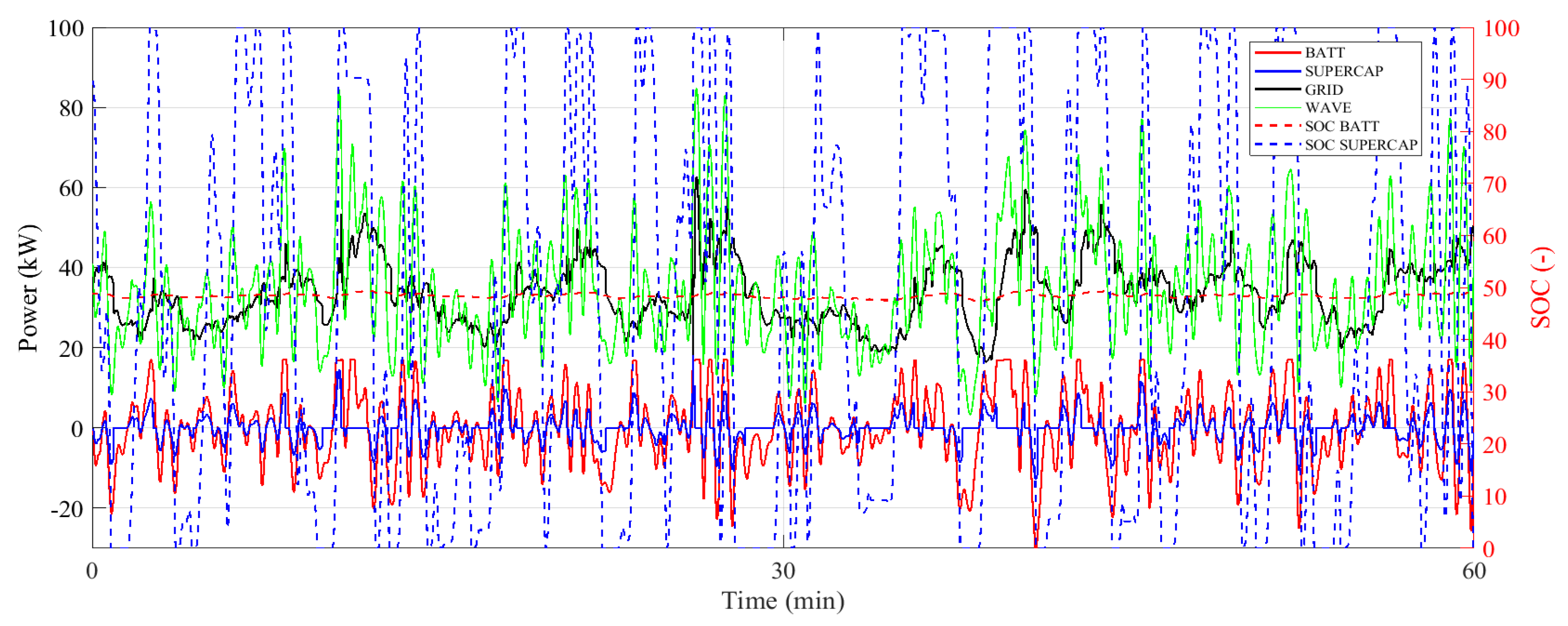
- Smooth the grid power profile by means of the ratio between the power delivered to the grid at timestep t and the power delivered at the previous instant (t − 1), as described by (8).
- Smooth the Li-ion battery-managed power profile by means of the ratio between the battery power at timestep t and the one at the previous instant (t − 1), as expressed by (9).
2.3. Dynamic Modeling of the System
- -
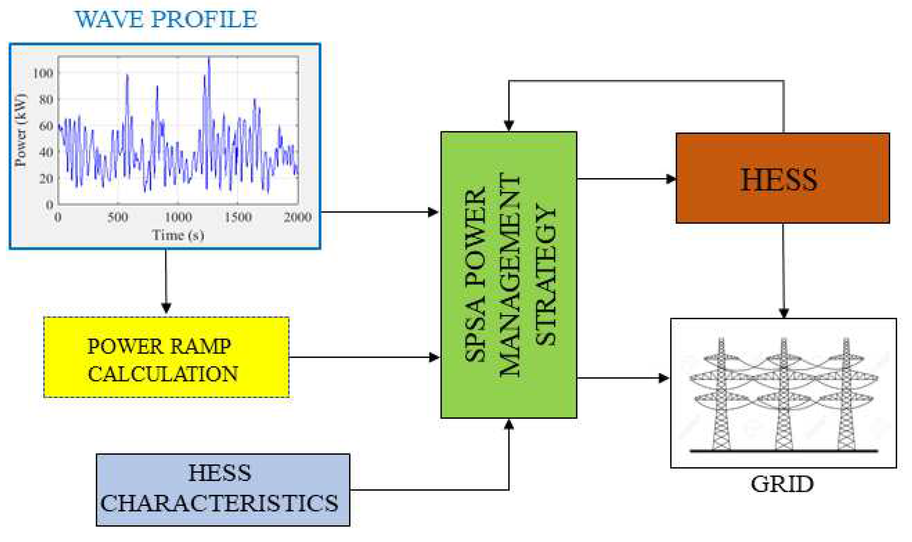
- The instantaneous daily power profile generated by the WEC, used as the input for computing the optimal power shares in the power management section.
- -
- The power management strategy, based on the SPSA algorithm, which instantaneously controls the power shares among the components and the grid, taking into account the power ramp values at the previous step and the HESS technical features and states of charge.
- -
- The HESS module composed of two subsystems related to the Li-ion battery pack and supercapacitor pack, respectively. The battery and supercapacitor implementation in the model are described in the following paragraphs.
- -
- The grid.
- -
- Li-Ion Battery
- -
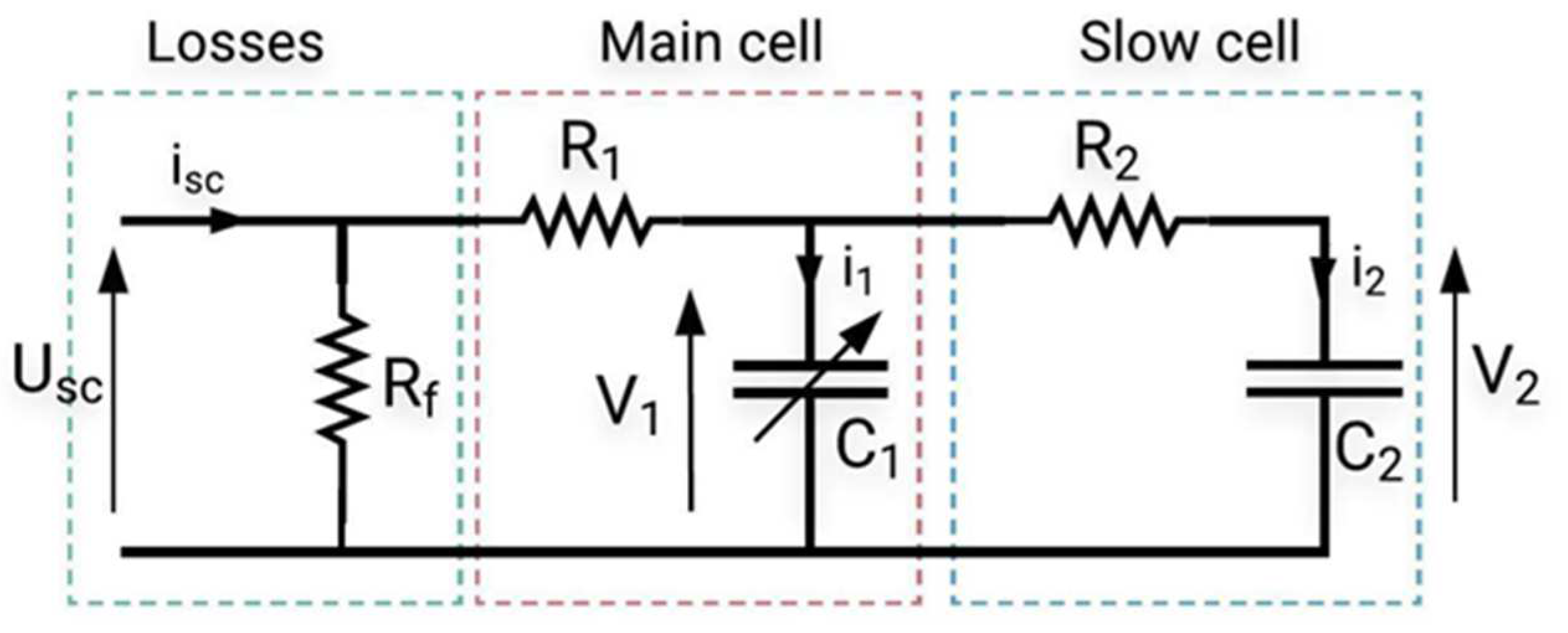
- Supercapacitor
- -
- The SC state of charge current value (SOCcap), obtained as the ratio between the integral of the current isc and the charge nominal value (Qnom).
- -
- The actual instantaneous power managed by the SC.
2.4. Sizing Procedure of the Hybrid Energy Storage System
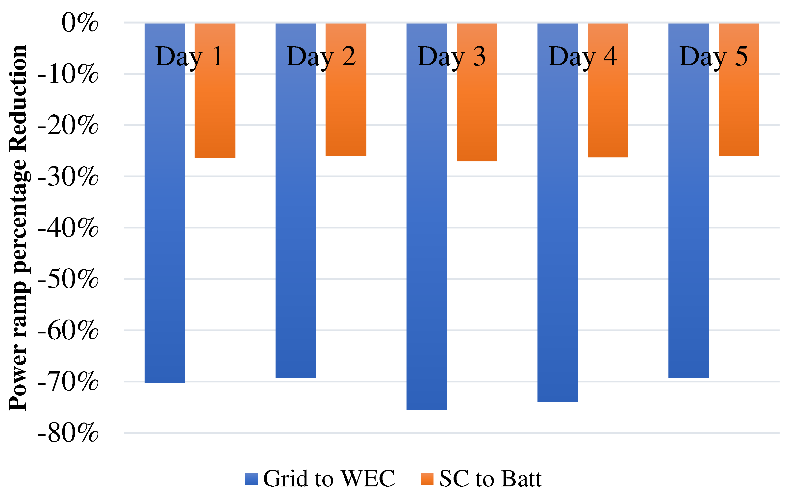
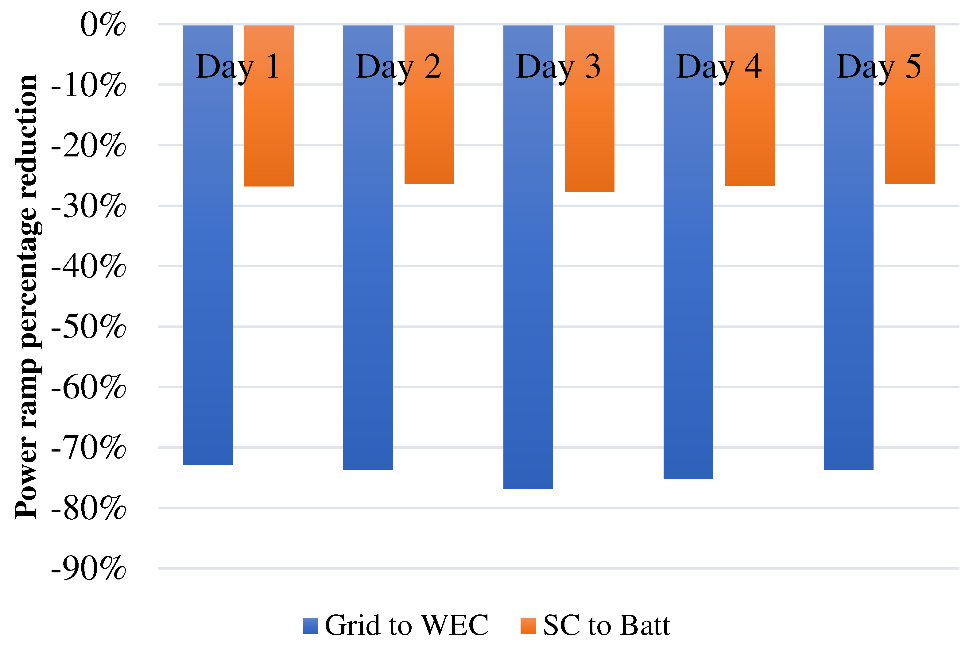
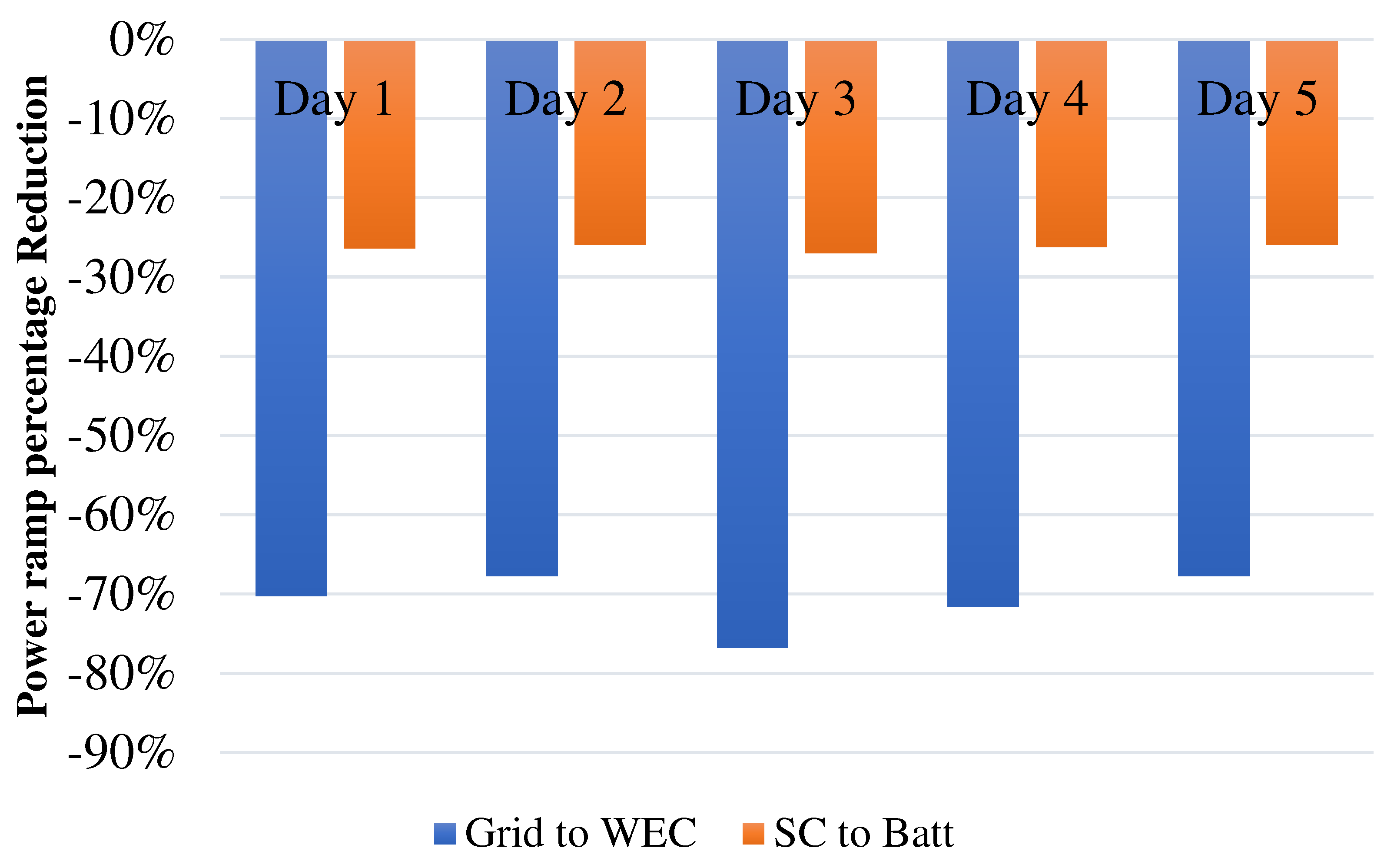
- With respect to the fluctuation at the WEC terminals, an average instantaneous percentage reduction in the power rate sent to the grid of at least −70% among all the considered days for the specific site, as expressed by Equation (23):where and represent the power ramp values, in W/s, assessed at an 80% CDF threshold for the grid and WEC power ramp, respectively.
- With respect to the SC’s absence, an average instantaneous percentage reduction in the power ramp managed by the battery was targeted thanks to the SC smoothing effect. Specifically, the power ramp managed by the SC was fixed to be equal to at least 25% of the total power ramp managed by the HESS among all the considered days for the specific site, as expressed by Equation (24):where and represent the power ramp values, in W/s, assessed at an 80% CDF threshold for the supercapacitor and battery, respectively.
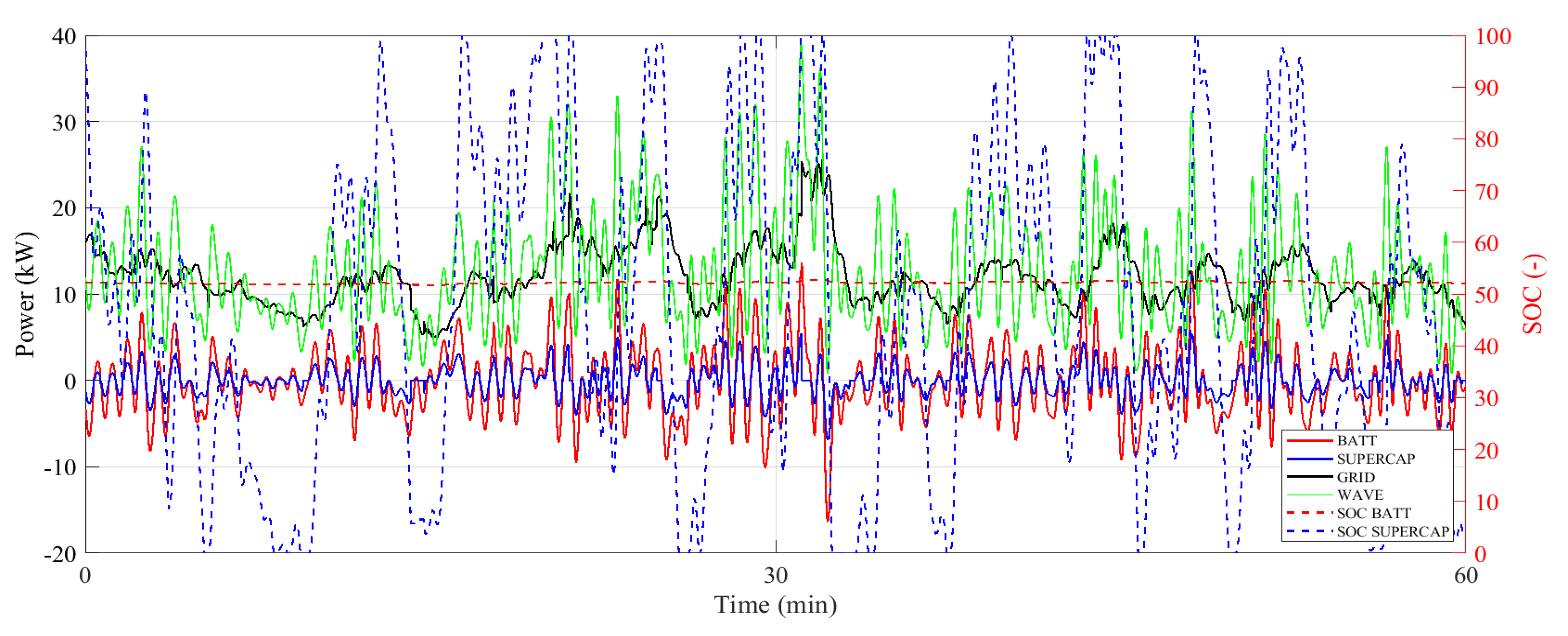
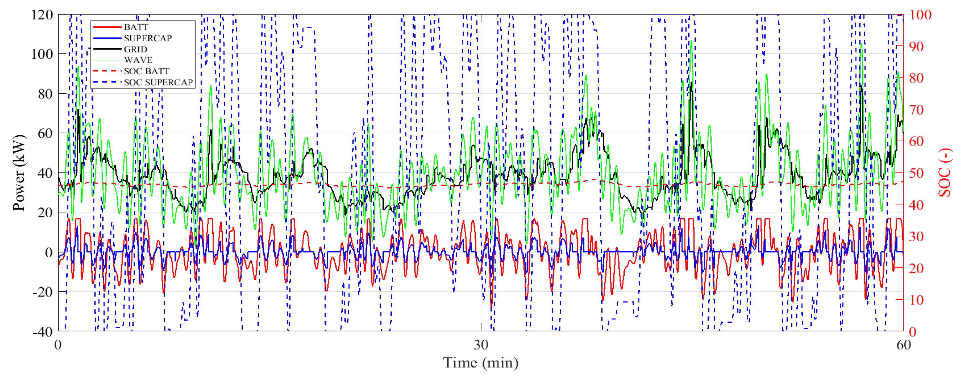
3. Results and Discussion
4. Conclusions
Author Contributions
Funding
Data Availability Statement
Conflicts of Interest
References
- IRENA. Wave Energy Technology Brief; IRENA: Masdar City, United Arab Emirates, 2014. [Google Scholar]
- Data & Statistics—IEA. Available online: https://www.iea.org/data-and-statistics?country=WORLD&fuel=Energy%20consumption&indicator=Electricity%20consumption (accessed on 21 September 2020).
- Brahmendra Kumar, G.V.; Sarojini, R.K.; Palanisamy, K.; Padmanaban, S.; Holm-Nielsen, J.B. Large Scale Renewable Energy Integration: Issues and Solutions. Energies 2019, 12, 1996. [Google Scholar] [CrossRef]
- Qiao, D.; Haider, R.; Yan, J.; Ning, D.; Li, B. Review of Wave Energy Converter and Design of Mooring System. Sustainability 2020, 12, 8251. [Google Scholar] [CrossRef]
- Falcao, A.F.D.O. Wave Energy Utilization: A Review of the Technologies. Renew. Sustain. Energy Rev. 2010, 14, 899–918. [Google Scholar] [CrossRef]
- Aderinto, T.; Li, H. Ocean Wave Energy Converters: Status and Challenges. Energies 2018, 11, 1250. [Google Scholar] [CrossRef]
- Zahedi, A. Maximizing Solar PV Energy Penetration Using Energy Storage Technology. Renew. Sustain. Energy Rev. 2011, 15, 866–870. [Google Scholar] [CrossRef]
- Rojas-Delgado, B.; Alonso, M.; Amaris, H.; De Santiago, J. Wave Power Output Smoothing through the Use of a High-Speed Kinetic Buffer. Energies 2019, 12, 2196. [Google Scholar] [CrossRef]
- Torres, J.; Blanco, M.; Lafoz, M.; Navarro, G.; Nájera, J.; Santos-Herran, M. Dimensioning Methodology of Energy Storage Systems for Power Smoothing in a Wave Energy Conversion Plant Considering Efficiency Maps and Filtering Control Techniques. Energies 2020, 13, 3380. [Google Scholar] [CrossRef]
- Wang, L.; Yu, J.Y.; Chen, Y.T. Dynamic Stability Improvement of an Integrated Offshore Wind and Marine-Current Farm Using a Flywheel Energy-Storage System. IET Renew. Power Gener. 2011, 5, 387–396. [Google Scholar] [CrossRef]
- Yoshida, T.; Sanada, M.; Morimoto, S.; Inoue, Y. Study of Flywheel Energy Storage System for Power Leveling of Wave Power Generation System. In Proceedings of the ICEMS 2012—Proceedings: 15th International Conference on Electrical Machines and Systems, Sapporo, Japan, 21–24 October 2012; IEEE: Denver, CO, USA, 2012. [Google Scholar]
- Moreno-Torres, P.; Blanco, M.; Navarro, G.; Lafoz, M. Power Smoothing System for Wave Energy Converters by Means of a Supercapacitor-Based Energy Storage System. In Proceedings of the 2015 17th European Conference on Power Electronics and Applications, EPE-ECCE Europe 2015, Geneva, Switzerland, 8–10 September 2015. Jointly owned by EPE Association and IEEE PELS. [Google Scholar]
- Murray, D.B.; Egan, M.G.; Hayes, J.G.; Sullivan, D.L.O. Applications of Supercapacitor Energy Storage for a Wave Energy Converter System. In Proceedings of the Eighth European Wave and Tidal Energy Conference, Uppsala, Sweden, 7–9 September 2009; pp. 786–795. [Google Scholar]
- Mongird, K.; Viswanathan, V.; Balducci, P.; Alam, J.; Fotedar, V.; Koritarov, V.; Hadjerioua, B. An Evaluation of Energy Storage Cost and Performance Characteristics. Energies 2020, 13, 3307. [Google Scholar] [CrossRef]
- Pelosi, D.; Barelli, L.; Longo, M.; Zaninelli, D. Assessment Analysis of BEV/PHEV Recharge in a Residential Micro-Grid Based on Renewable Generation. In Sustainability in Energy and Buildings 2022; Littlewood, J., Howlett, R.J., Jain, L.C., Eds.; Springer Nature: Singapore, 2023; pp. 130–139. [Google Scholar]
- Barelli, L.; Pelosi, D.; Longo, M.; Zaninelli, D. Energy Storage Integration into Fast Charging Stations Installed on E-Highways. In Proceedings of the 2022 IEEE Power & Energy Society General Meeting (PESGM), Denver, CO, USA, 17–21 July 2022; IEEE: Denver, CO, USA, 2022. [Google Scholar]
- Pelosi, D.; Longo, M.; Bidini, G.; Zaninelli, D.; Barelli, L. A New Concept of Highways Infrastructure Integrating Energy Storage Devices for E-Mobility Transition. J. Energy Storage 2023, 65, 107364. [Google Scholar] [CrossRef]
- Barelli, L.; Bidini, G.; Cherubini, P.; Micangeli, A.; Pelosi, D.; Tacconelli, C. How Hybridization of Energy Storage Technologies Can Provide Additional Flexibility and Competitiveness to Microgrids in the Context of Developing Countries. Energies 2019, 12, 3138. [Google Scholar] [CrossRef]
- Cheng, L.; Zhang, F.; Liu, S.; Zhang, Z. Configuration Method of Hybrid Energy Storage System for High Power Density in More Electric Aircraft. J. Power Sources 2020, 445, 227322. [Google Scholar] [CrossRef]
- Nie, Z.; Xiao, X.; Kang, Q.; Aggarwal, R.; Zhang, H.; Yuan, W. SMES-Battery Energy Storage System for Conditioning Outputs from Direct Drive Linear Wave Energy Converters. IEEE Trans. Appl. Supercond. 2013, 23, 5000705. [Google Scholar] [CrossRef]
- Barelli, L.; Bidini, G.; Ottaviano, P.A.; Gallorini, F.; Pelosi, D. Coupling Hybrid Energy Storage System to Regenerative Actuators in a More Electric Aircraft: Dynamic Performance Analysis and CO2 Emissions Assessment Concerning the Italian Regional Aviation Scenario. J. Energy Storage 2022, 45, 103776. [Google Scholar] [CrossRef]
- Şahin, M.E.; Blaabjerg, F. A Hybrid PV-Battery/Supercapacitor System and a Basic Active Power Control Proposal in MATLAB/Simulink. Electronics 2020, 9, 129. [Google Scholar] [CrossRef]
- Wan, C.; Qian, W.; Zhao, C.; Song, Y.; Yang, G. Probabilistic Forecasting Based Sizing and Control of Hybrid Energy Storage for Wind Power Smoothing. IEEE Trans. Sustain. Energy 2021, 12, 1841–1852. [Google Scholar] [CrossRef]
- Abdalla, A.A.; El Moursi, M.S.; El-Fouly, T.H.; Hosani, K.H. Al A Novel Adaptive Power Smoothing Approach for PV Power Plant with Hybrid Energy Storage System. IEEE Trans. Sustain. Energy 2023, 14, 1457–1473. [Google Scholar] [CrossRef]
- Nguyen, V.T.; Shim, J.W. Virtual Capacity of Hybrid Energy Storage Systems Using Adaptive State of Charge Range Control for Smoothing Renewable Intermittency. IEEE Access 2020, 8, 126951–126964. [Google Scholar] [CrossRef]
- Yuming, C.; Peng, J.; Gaojun, M.; Yao, W.; Tiantian, L. Optimal Capacity Configuration of Hybrid Energy Storage System Considering Smoothing Wind Power Fluctuations and Economy. IEEE Access 2022, 10, 101229–101236. [Google Scholar] [CrossRef]
- Bharatee, A.; Ray, P.K.; Ghosh, A. A Power Management Scheme for Grid-Connected PV Integrated with Hybrid Energy Storage System. J. Mod. Power Syst. Clean Energy 2022, 10, 954–963. [Google Scholar] [CrossRef]
- Hazra, S.; Bhattacharya, S. Hybrid Energy Storage System Comprising of Battery and Ultra-Capacitor for Smoothing of Oscillating Wave Energy. In Proceedings of the ECCE 2016 IEEE Energy Conversion Congress and Exposition, Milwaukee, WI, USA, 18–22 September 2016; pp. 8–15. [Google Scholar] [CrossRef]
- Fang, H.; Lin, S.; Chu, H.; Jia, T.; Liu, Y. Coordinated and Stable Control of a Hybrid Energy Storage System for Wave Generation System. In Proceedings of the World Congress on Intelligent Control and Automation (WCICA), Guilin, China, 12–15 June 2016; pp. 1986–1991. [Google Scholar]
- Pelosi, D.; Baldinelli, A.; Cinti, G.; Ciupageanu, D.A.; Ottaviano, A.; Santori, F.; Carere, F.; Barelli, L. Battery-hydrogen vs. flywheel-battery hybrid storage systems for renewable energy integration in mini-grid: A techno-economic comparison. J. Energy Storage 2023, 63, 106968. [Google Scholar] [CrossRef]
- Barelli, L.; Bidini, G.; Ciupageanu, D.A.; Ottaviano, A.; Pelosi, D.; Gallorini, F.; Alessandri, G.; Atcheson Cruz, M. An Effective Solution to Boost Generation from Waves: Benefits of a Hybrid Energy Storage System Integration to Wave Energy Converter in Grid-Connected Systems. Open Res. Eur. 2022, 2, 40. [Google Scholar] [CrossRef]
- Pecher, A.; Kofoed, J.P. Handbook of Ocean Wave Energy; SpringerOpen: Berlin/Heidelberg, Germany, 2017; ISBN 9783319398884. [Google Scholar]
- Barelli, L.; Bidini, G.; Ciupageanu, D.A.; Micangeli, A.; Ottaviano, P.A.; Pelosi, D. Real Time Power Management Strategy for Hybrid Energy Storage Systems Coupled with Variable Energy Sources in Power Smoothing Applications. Energy Rep. 2021, 7, 2872–2882. [Google Scholar] [CrossRef]
- Neffati, A.; Guemri, M.; Caux, S.; Fadel, M. Energy Management Strategies for Multi Source Systems. Electr. Power Syst. Res. 2013, 102, 42–49. [Google Scholar] [CrossRef]
- Byrne, R.H.; Nguyen, T.A.; Copp, D.A.; Chalamala, B.R.; Gyuk, I. Energy Management and Optimization Methods for Grid Energy Storage Systems. IEEE Access 2017, 6, 13231–13260. [Google Scholar] [CrossRef]
- Ciupageanu, D.A.; Barelli, L.; Lazaroiu, G. Real-time stochastic power management strategies in hybrid renewable energy systems: A review of key applications and perspectives. Electr. Power Syst. Res. 2020, 187, 106497. [Google Scholar] [CrossRef]
- Barelli, L.; Pelosi, D.; Ciupageanu, D.A.; Ottaviano, P.A.; Lazaroiu, G. Stochastic Power Management Strategy for Hybrid Energy Storage Systems to Enhance Large Scale Wind Energy Integration. J. Energy Storage 2020, 31, 101650. [Google Scholar] [CrossRef]
- Spall, J.C. Multivariate Stochastic Approximation Using a Simultaneous Perturbation Gradient Approximation. IEEE Trans. Autom. Contr. 1992, 37, 332–341. [Google Scholar] [CrossRef]
- Sadegh, P.; Spall, J.C. Optimal Random Perturbation for Stochastic Approximation Using a Simultaneous Perturbation Gradient Approximation. IEEE Trans. Autom. Contr. 1998, 43, 1480–1484. [Google Scholar] [CrossRef]
- Spall, J.C. An Overview of the Simultaneous Perturbation Method. Johns Hopkins APL Tech. Dig. 1998, 19, 482–492. [Google Scholar]
- Spall, J.C. A One-Measurement Form of Simultaneous Perturbation Stochastic Approximation. Automatica 1997, 33, 109–112. [Google Scholar] [CrossRef]
- Ho, M.C.; Lim, J.M.-Y.; Chong, C.Y.; Chua, K.K.; Siah, A.K.L. High Dimensional Origin Destination Calibration Using Metamodel Assisted Simultaneous Perturbation Stochastic Approximation. IEEE Trans. Intell. Transp. Syst. 2023, 24, 3845–3854. [Google Scholar] [CrossRef]
- Granichin, O.; Erofeeva, V.; Ivanskiy, Y.; Jiang, Y. Simultaneous Perturbation Stochastic Approximation-Based Consensus for Tracking under Unknown-But-Bounded Disturbances. IEEE Trans. Automat. Contr. 2021, 66, 3710–3717. [Google Scholar] [CrossRef]
- GWL Power. GB-LFP1865-11 Rechargeable Battery Datasheet; GWL Power Ltd.: Prague, Czech Republic, 2016. [Google Scholar]
- Maxwell Technologies. 2.7V 650-3000F Ultracapacitor Cells Datasheet; Maxwell Technologies: San Diego, CA, USA, 2019. [Google Scholar]
- Lahyani, A.; Venet, P.; Guermazi, A.; Troudi, A. Battery/Supercapacitors Combination in Uninterruptible Power Supply (UPS). IEEE Trans. Power Electron. 2013, 28, 1509–1522. [Google Scholar] [CrossRef]


| Site 1 | Site 2 | Site 3 | ||||
|---|---|---|---|---|---|---|
| μ | σ | μ | σ | μ | σ | |
| Bandwidth (kW) | 399 | 5 | 397 | 10 | 400 | 0.5 |
| Maximum bandwidth-to-mean-power ratio (-) | 13.2 | 1.8 | 18 | 2.7 | 12.6 | 2.2 |
| μ | min/max | μ | min/max | μ | min/max | |
| Power ramp (kW/s) | 2.8 | 0–7.5 | 2.1 | 0–6.3 | 3 | 0–8 |
| Power (kW) | 31 | 0–81 | 22 | 0–66 | 32 | 0–86 |
| SC Equivalent Parameters | |
|---|---|
| 2.33 mΩ | |
| 380 F | |
| 262 F V−1 | |
| 0.8126 Ω | |
| 117 F | |
| 2.7 V | |
| 2.85 V | |
| 650 F | |
| 1 kW | |
| Cell weight | 0.16 kg |
| Site 1–Site 2–Site 3 | |||
|---|---|---|---|
| Total Cell Number | Power [kw] | Capacity [kWh] | |
| Supercapacitor | 60 parallel | 65.3 | 0.026 |
| Li-ion battery | 100 series | 72 | 24 |
| PRbatt (W/s) | PRsc (W/s) | PRWEC (W/s) | PRgrid (W/s) | |
|---|---|---|---|---|
| Day 1 | 1788 | 640 | 2487 | 739 |
| Day 2 | 1941 | 681 | 2732 | 840 |
| Day 3 | 1022 | 378 | 1404 | 345 |
| Day 4 | 1338 | 476 | 1839 | 480 |
| Day 5 | 1941 | 681 | 2732 | 840 |
| PRbatt (W/s) | PRsc (W/s) | PRWEC (W/s) | PRgrid (W/s) | |
|---|---|---|---|---|
| Day 1 | 1493 | 546 | 2104 | 573 |
| Day 2 | 1650 | 590 | 2314 | 609 |
| Day 3 | 835 | 320 | 1153 | 267 |
| Day 4 | 1280 | 468 | 1767 | 439 |
| Day 5 | 1650 | 590 | 2314 | 609 |
| PRbatt (W/s) | PRsc (W/s) | PRWEC (W/s) | PRgrid (W/s) | |
|---|---|---|---|---|
| Day 1 | 1640 | 594 | 2278 | 678 |
| Day 2 | 2300 | 818 | 3292 | 1063 |
| Day 3 | 1048 | 391 | 1451 | 337 |
| Day 4 | 1633 | 592 | 2256 | 642 |
| Day 5 | 2300 | 818 | 3292 | 1063 |
Disclaimer/Publisher’s Note: The statements, opinions and data contained in all publications are solely those of the individual author(s) and contributor(s) and not of MDPI and/or the editor(s). MDPI and/or the editor(s) disclaim responsibility for any injury to people or property resulting from any ideas, methods, instructions or products referred to in the content. |
© 2024 by the authors. Licensee MDPI, Basel, Switzerland. This article is an open access article distributed under the terms and conditions of the Creative Commons Attribution (CC BY) license (https://creativecommons.org/licenses/by/4.0/).
Share and Cite
Pelosi, D.; Gallorini, F.; Alessandri, G.; Barelli, L. A Hybrid Energy Storage System Integrated with a Wave Energy Converter: Data-Driven Stochastic Power Management for Output Power Smoothing. Energies 2024, 17, 1167. https://doi.org/10.3390/en17051167
Pelosi D, Gallorini F, Alessandri G, Barelli L. A Hybrid Energy Storage System Integrated with a Wave Energy Converter: Data-Driven Stochastic Power Management for Output Power Smoothing. Energies. 2024; 17(5):1167. https://doi.org/10.3390/en17051167
Chicago/Turabian StylePelosi, Dario, Federico Gallorini, Giacomo Alessandri, and Linda Barelli. 2024. "A Hybrid Energy Storage System Integrated with a Wave Energy Converter: Data-Driven Stochastic Power Management for Output Power Smoothing" Energies 17, no. 5: 1167. https://doi.org/10.3390/en17051167
APA StylePelosi, D., Gallorini, F., Alessandri, G., & Barelli, L. (2024). A Hybrid Energy Storage System Integrated with a Wave Energy Converter: Data-Driven Stochastic Power Management for Output Power Smoothing. Energies, 17(5), 1167. https://doi.org/10.3390/en17051167