Article

Porous Prussian Blue Analogs Decorated Electrospun Carbon Nanofibers as Efficient Electrocatalyst for Overall Water Splitting

1
School of Materials Science and Engineering, Ocean University of China, Qingdao 266100, China
2
Institute for Chemical Biology & Biosensing, College of Life Sciences, Qingdao University, Qingdao 266071, China
*
Authors to whom correspondence should be addressed.
Energies 2024, 17(5), 1154; https://doi.org/10.3390/en17051154
Submission received: 23 January 2024 / Revised: 15 February 2024 / Accepted: 26 February 2024 / Published: 29 February 2024
(This article belongs to the Special Issue Advanced Materials and Technologies for Hydrogen Evolution)

Abstract

:
Metal-organic frameworks are becoming increasingly important in electrocatalysis as the hydrogen production sector grows. However, their electrocatalytic capability is limited by their inclination to agglomerate and the insufficient exposure of active sites. In this work, a three-step strategy was used to develop a bifunctional electrocatalyst with porous Prussian blue analogs supported on carbon nanofibers. The use of electrospun carbon nanofibers as conductive substrates can successfully address the problem of easy aggregation. Moreover, the etching procedure with tannic acid creates a porous structure that effectively regulates the electrical structure and exposes additional active sites. The resulting catalyst performs well in both the hydrogen evolution reaction and the oxygen evolution reaction, and also exhibits good stability in overall water splitting. The findings of this study present new concepts for the design and fabrication of metal-organic frameworks-based materials in the realm of electrocatalysis.

1. Introduction

The search for alternative fuels has gained increasing significance in addressing the energy crisis [1,2]. Hydrogen has emerged as a prominent fuel and has garnered considerable attention [3]. Various methods exist for hydrogen evolution, with electrocatalytic water splitting being widely regarded as a promising solution due to its renewability and environmental sustainability [4,5,6]. Water splitting involves two key reaction processes: the oxygen evolution reaction (OER) and the hydrogen evolution reaction (HER) [7,8,9,10]. However, the overall efficiency of water electrolysis is hindered by the slow kinetics of these reactions. The widespread industrial implementation of electrocatalytic water splitting necessitates the advancement of electrocatalysts that exhibit high activity, low cost, and robust durability. In the realm of electrocatalytic water splitting, precious metals are acknowledged as highly efficient catalysts owing to their high activity [11,12,13,14]. Nevertheless, their high cost presents a barrier to widespread commercial adoption. Therefore, there is an urgent need to design cost-effective and high-performing catalysts as alternatives to precious metals [15,16,17].
Due to their extensive surface area, plentiful pores, and adaptable morphological characteristics, metal-organic frameworks (MOFs) have attracted considerable interest in the realms of energy and environment [18,19,20]. Pristine MOFs have been demonstrated as advanced electrocatalysts for both the HER and OER. For example, Choi and colleagues developed a novel approach to create transition-metal-based 3D MOF materials with diverse architectures using pulsed laser ablation in organic solvent [21]. The resulting MOF materials have metal ligands that are prominently exposed to the metal active sites, leading to an enhanced electrochemical performance. The Co-MOF demonstrates superior electrochemical performance in both half-cell reactions (HER and OER) and overall water splitting. This is attributed to the high theoretical catalytic activity of cobalt, which is associated with its low energy barrier for hydrogen adsorption. Notably, pristine MOFs may experience the aggregation of active species, resulting in limited exposure of active sites and reduced structural stability in alkaline environments. To address these challenges, it is common practice to incorporate a conductive substrate to provide structural support for the MOF [22,23,24]. Liao et al. designed a cerium-doped Co-MOF grown on carbon paper in the shape of a nanoflower [25]. The composite exhibited ideal OER performance, with a low overpotential to achieve the targeted current density. The insertion of carbon paper has strong support and the ability to transport electrons. The structural feature provides the electrocatalyst with abundant channels. In another example, Tian et al. developed a binder-free hybrid electrocatalyst for water splitting on Ni foam by incorporating P-doped MOF materials [26]. This hybrid architecture, consisting of 2D nanosheets and 3D nanospheres, was designed to enhance mass transport and expose active sites. The Ni foam can enhance electron pathways and increase surface area, resulting in a larger electrode—electrolyte contact area.
Prussian blue analogs (PBAs) are typical MOFs made up of metal ions, transition metal ions, and ligands [27]. PBAs have the structural advantages of MOFs, as well as the simplicity of the synthesis process, low cost, and outstanding electrochemical performance [28]. Therefore, PBAs have shown promise as an electrode material for water splitting. Using an iterative coprecipitation method, Zhang et al. created trimetallic heterostructured core-shell nanoboxes based on PBA. The PBA core and shell were created with the shell synthesized via chemical etching. Because of its unique structure and composition, the obtained Ni-Co@Fe-Co PBA has more exposed active sites and possesses excellent electrocatalytic HER performance [29]. Despite the advancements made, the development of a proficiently designed PBA-based bifunctional electrocatalyst for the overall water splitting process remains a challenging endeavor [30,31,32,33].
Herein, bimetallic PBAs have been successfully decorated on conductive electrospun carbon nanofibers (CNFs) to create a composite electrocatalyst. Tannic acid (TA) was introduced to etch the assembled PBA, resulting in abundant nanopores on the PBA and exposed metal active sites. The contact area between the developed electrocatalyst and the electrolyte solution has been increased, and the charge transfer has been promoted. The optimized electrocatalyst exhibited a low overpotential of 139 mV (for HER) and 342 mV (for OER) at 10 mA cm−2 in 1 M KOH electrolyte. The durability of the electrocatalyst was excellent because of the supportive CNFs.

2. Experimental Section

2.1. Materials

Potassium hydroxide (KOH), sulfuric acid (H2SO4), hydrochloric acid (HCl), ethanol, N,N dimethylformamide (DMF), and potassium ferricyanide (K3 [Fe(CN)6], 98.0%) were purchased from Sinopharm Chemical Reagent Co., Ltd. (Shanghai, China). Polyacrylonitrile (PAN, Mw = 150,000), Nafion solution (5 wt%) and RuO2 (99.9%) were purchased from Sigma Aldrich (China). Polyvinyl pyrrolidone (PVP, Mw = 1,300,000) and tannic acid (TA) were purchased from Aladdin (Shanghai, China). Cobalt acetylacetonate (97.0%) was acquired from Macklin Biochemical Technology Co., Ltd. (Shanghai, China). Pt/C (20 wt%) was obtained from Alfa Aesar (China).

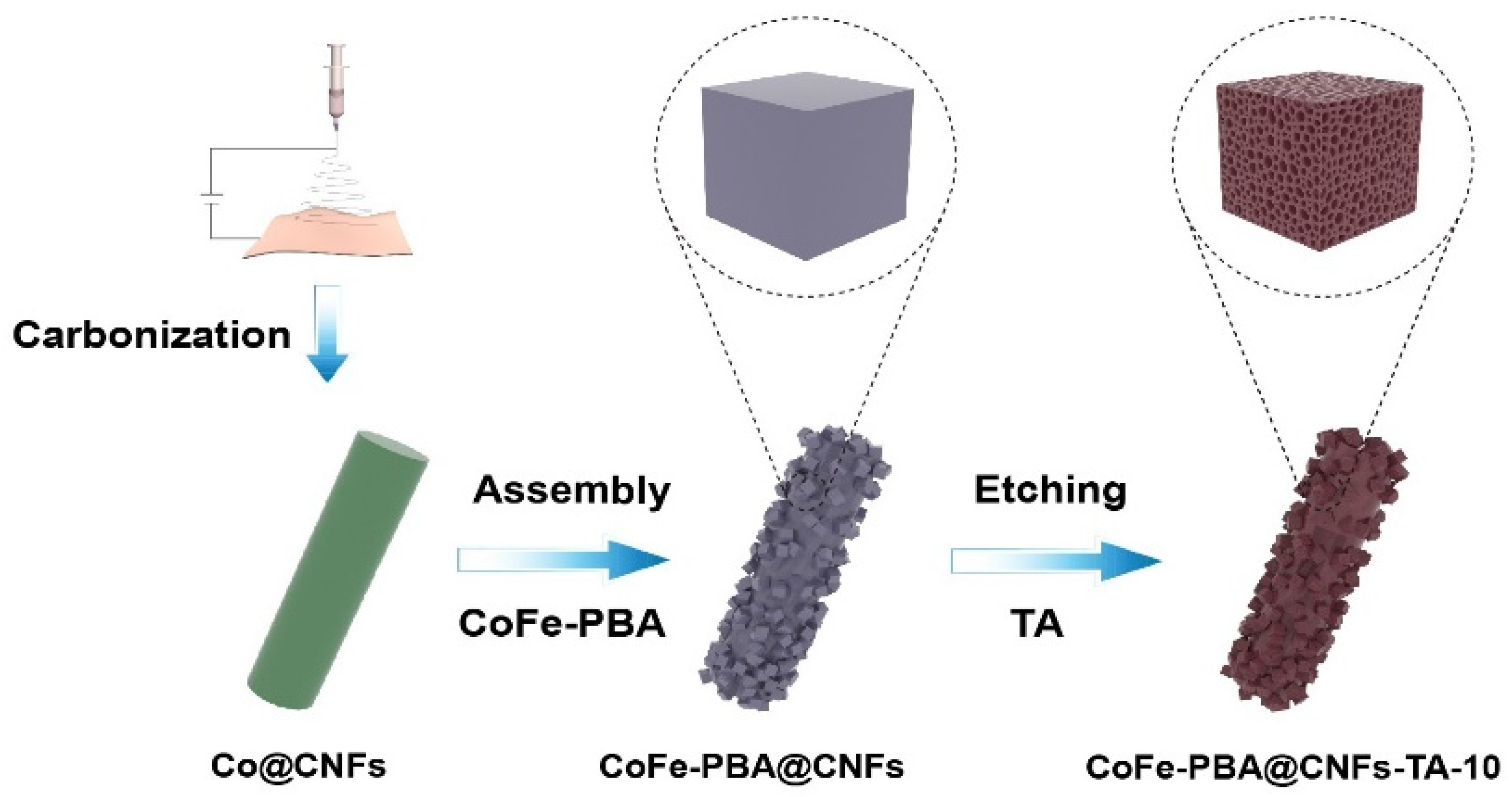
2.2. Preparation of Catalysts

First, 0.2 g PVP and 1.0 g PAN were dissolved in 10 mL DMF and magnetically stirred into a uniform solution. Then, 0.5 g cobalt acetylacetonate power was added and stirred for 6 h to prepare electrospinning precursor solution. The flow rate of the precursor solution was set to 0.017 mL min−1 for collection. The distance from the tip to the receiving aluminum foil was 12 cm and the voltage of the electrospinning was 14 kV. Finally, a piece of light pink nanofiber membrane was obtained. The fiber membrane was oxidized at 240 °C in air atmosphere for 1 h, and then carbonized at 800 °C in nitrogen atmosphere for 2 h with a heating rate of 5 °C min−1. The obtained sample was named as Co@CNFs.
The CoFe-PBA@CNFs composite was synthesized through a straightforward assembly process. Initially, the Co@CNFs membrane was immersed in a 0.1 M K3 [Fe(CN)6] solution and agitated gently for 5 min to achieve uniform soaking. Subsequently, a diluted hydrochloric acid was gradually introduced into the solution until the pH reached 1, and the soaking process was continued for 6 h. Following the reaction, the resulting product was thoroughly rinsed with a substantial quantity of deionized water and subsequently subjected to vacuum drying at 60 °C to yield CoFe-PBA@CNFs.
Next, 0.1 g tannic acid powder was dissolved in 20 mL deionized water to form a TA solution. The obtained CoFe-PBA@CNFs was then immersed in the TA solution and etched for 10 min. Subsequently, it was rinsed with deionized water and ethanol multiple times before being dried under vacuum at 60 °C for several hours. This process led to the synthesis of CoFe-PBA@CNFs-TA-10. To investigate the impact of etching duration, additional control samples were etched for 5 min (CoFe-PBA@CNFs-TA-5) and 15 min (CoFe-PBA@CNFs-TA-15), respectively.

2.3. Materials Characterization

The microstructures of the catalyst were examined using a scanning electron microscope (SEM, ZEISS Gemini 300) and a transmission electron microscope (TEM, FEI Tecnai F20). The catalyst’s elemental composition was studied using an X-ray diffractometer (XRD, Bruker D8 Advance) in the 2θ range of 10 to 90°. Raman spectroscopy (Renishaw in Via) was investigated using a 532 nm laser. The valence states of elements on the catalyst were determined using an X-ray photoelectron spectroscopy (XPS, Thermo Fisher ESCALAB 250Xi). Micromeritics TriStar II3020 was used to collect isotherms of N2 adsorption and desorption.

2.4. Electrochemical Measurements

The electrochemical measurements were conducted using a standard three-electrode system in 1.0 M KOH, controlled by a CHI 630E (Shanghai Chenhua, China) electrochemical workstation. The working electrode was a glassy carbon electrode with a 5 mm diameter, coated with the catalyst. The reference electrode was an Ag/AgCl electrode, and the counter electrode was a graphite rod. Prior to the electrochemical test, the electrolyte was purged with nitrogen for 30 min to eliminate air in the solution. 90% iR compensation was applied to all the experimental data. All the potentials presented in this work were calibrated to the reversible hydrogen electrode by using the equation (ERHE = EAg/AgCl + 0.059×pH + 0.197 V). Linear sweep voltammetry (LSV) curves were obtained at a sweep rate of 5 mV s−1 in the potential range of 0.1 V to 0.3 V (vs. RHE). The double layer capacitance (Cdl) was determined using cyclic voltammetry (CV) at scan rates of 10, 20, 30, 40, and 50 mV s−1. Electrochemical impedance spectroscopy (EIS) was performed within a frequency range of 0.1 to 105 Hz, with a test potential of −0.2 V (vs. RHE) in 1.0 M KOH. For stability tests, the CV potential ranged from 0.1 to −0.2 V (vs. RHE), and the scan rate was 100 mV s−1. LSV curves were measured before and after 2000 CV cycles. The chronoamperometry curve was obtained by testing the electrocatalyst at a specific potential. A 5 mg catalyst was dispersed in a mixed solution of 480 μL ethanol and 20 μL 5 wt% nafion solution, and then treated with ultrasonic for 30 min to form a uniform slurry. Finally, 100 μL of the catalyst slurry was slowly dropped onto a piece of nickel foam (1 cm × 1 cm) to obtain both cathode and anode for overall water splitting, with a loading amount of 1 mg cm−2.

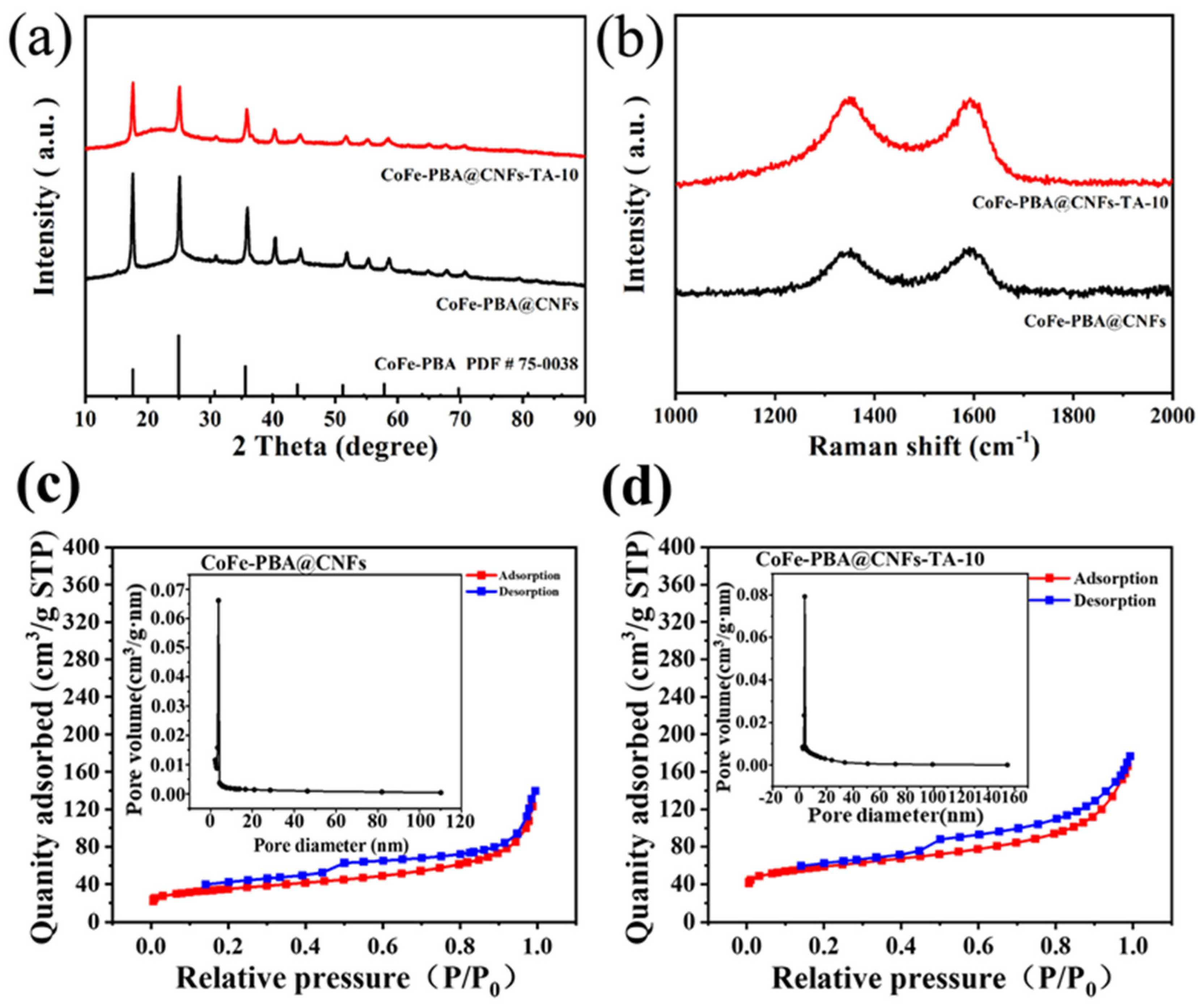
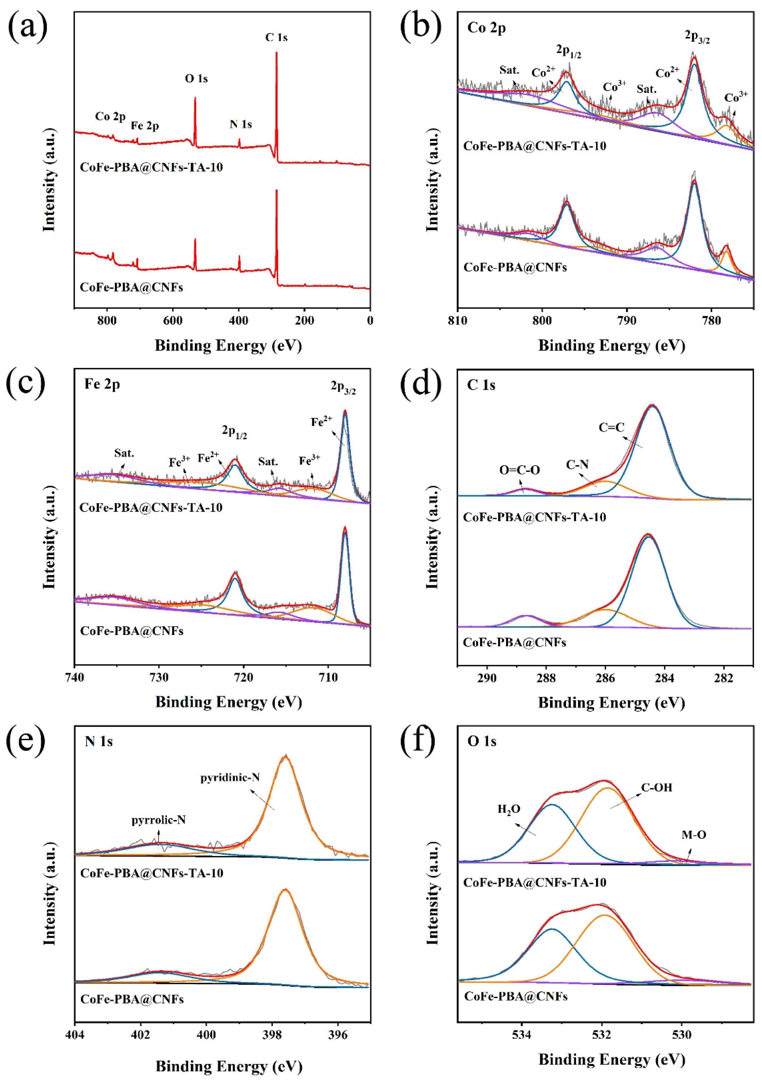
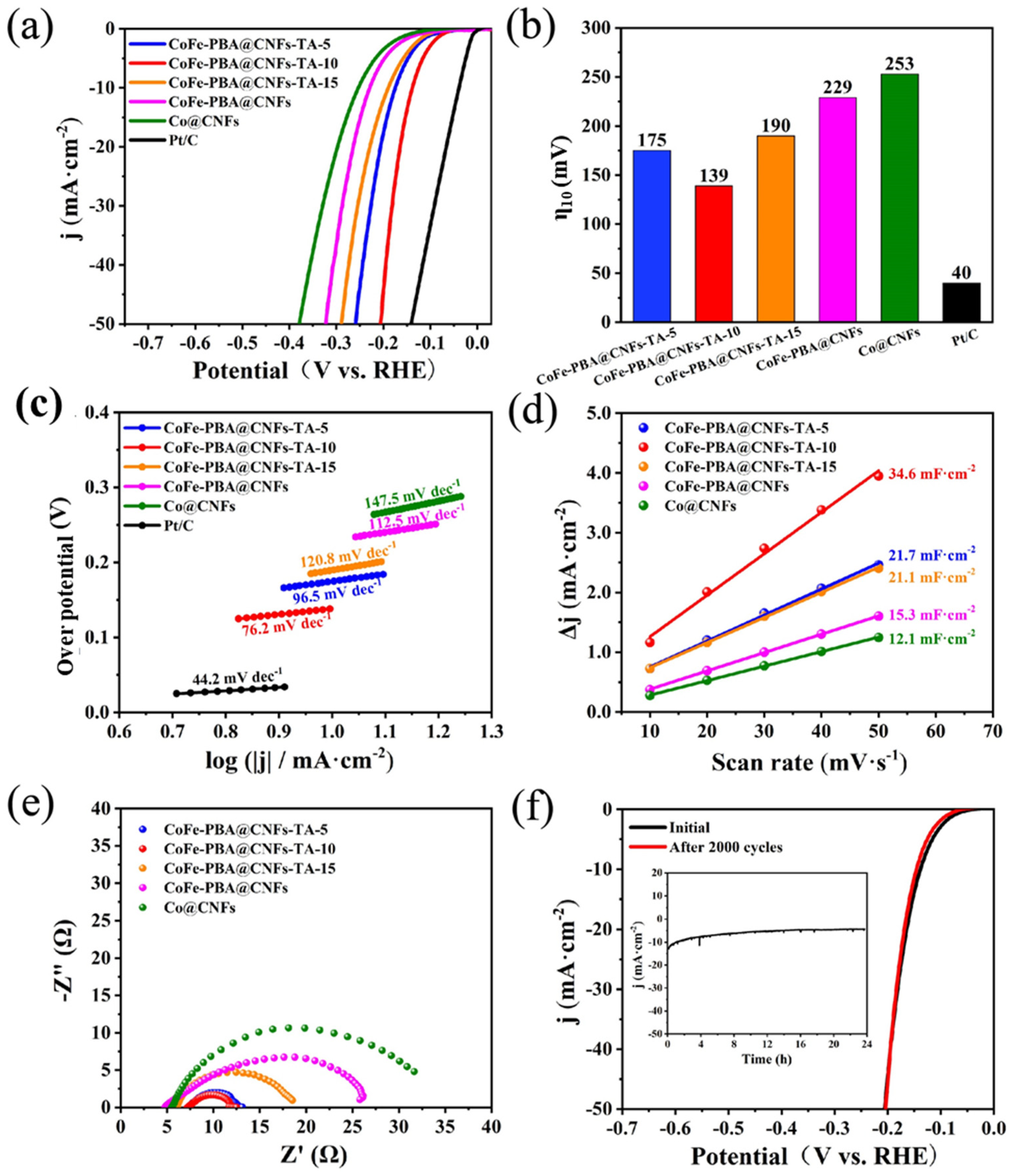
3. Results and Discussion

The preparation process of the CoFe-PBA@CNFs-TA-10 catalyst is shown in Figure 1. Firstly, the Co@CNFs nanofibrous membrane was prepared through electrospinning and calcination. After being soaked in K3 [Fe(CN)6] solution, Co2+ and K3 [Fe(CN)6] assembled on the surface of the fiber, forming CoFe-PBA nanocubes. Finally, the CoFe-PBA@CNFs-TA-10 catalyst was fabricated through a facile TA etching process.
The SEM image of the Co@CNFs is shown in Figure 2a. The nanofibers have a high aspect ratio and a uniform diameter of approximately 500 nm. During the following assembly process, Co2+ as metal source and K3 [Fe(CN)6] as ligand were assembled on the surface of the nanofibers to form CoFe-PBA nanocubes, as depicted in Figure 2b [34]. In addition, a diluted HCl solution was slowly added to the K3 [Fe(CN)6] solution in order to activate Co species from the fiber surface and promote the growth of CoFe-PBA on the fiber [35]. The uniformly dispersed CoFe-PBA crystals on the fiber surface have a regular cubic structure with 100 nm in edge length. In contrast, serious agglomeration occurs when the CoFe-PBAs are prepared without a supporting matrix, which is not conducive to the exposure of catalytically active sites. After the TA etching process, a large number of holes and cracks (highlighted with white circles in Figure 2c,d) are generated on the smooth surface of CoFe-PBA nanocubes. As shown in Figure 2e,f, small nanocubes with nanoholes are attached to the surface of the carbon nanofibers, and this morphology is propitious to the increase in the active sites and the transportation of electrons. The lattice spacing of the crystal is 0.204 nm, which belongs to the (400) lattice plane of the CoFe-PBA crystals [36,37,38]. The presence of CoFe-PBA is also confirmed by the electron diffraction image in Figure 2g, which suggests that the TA etching process did not alter the pristine CoFe-PBA’s crystal structure. The image consists of several crystalline surfaces with discrete spots that correspond to CoFe-PBA. The corresponding element mapping images (Figure 2h) reveal that the C, N, O, Co, and Fe elements are evenly distributed on the nanofibers.
The XRD analysis of the prepared CoFe-PBA@CNFs and CoFe-PBA@CNFs-TA-10, as depicted in Figure 3a, reveals diffraction peaks at 17.5°, 24.9°, and 35.6°, corresponding to the crystal faces (200), (220), and (400) of K2Co [Fe(CN)6] (JCPDS no. 75-0038), respectively [4]. These distinct diffraction peaks indicate the high crystallinity and purity of the obtained CoFe-PBA nanocubes. The diffraction peaks obtained from CoFe-PBA@CNFs-TA-10 were found to be similar to those obtained from CoFe-PBA@CNFs, confirming that the etching process did not affect the crystal structure of the porous material [7]. Furthermore, Raman spectral analysis was performed to elucidate the structure of the catalysts, as shown in Figure 3b. The two characteristic broad peaks located at 1351 cm−1 and 1592 cm−1 belong to the typical defect induction band (D band) of carbon and the graphite induction band (G band), respectively [39]. Considering the increase in the D band, there is an increment in the degree of defects for the CoFe-PBA@CNFs-TA-10 sample.
Moreover, nitrogen adsorption–desorption isotherms and pore size distribution curves for CoFe-PBA@CNFs and CoFe-PBA@CNFs-TA-10 are presented in Figure 3c,d. According to the Brunauer–Emmet–Teller model, the specific surface areas of the CoFe-PBA@CNFs and CoFe-PBA@CNFs-TA-10 samples were determined to be 125.2 m2 g−1 and 211.9 m2 g−1, respectively. Notably, CoFe-PBA@CNFs-TA-10 exhibited a larger specific surface area, which could enhance the direct contact between the catalyst and the electrolyte solution. Additionally, the characteristic type IV curve and the pore size distribution concentrated around 3 nm indicate a mesoporous structure of the CoFe-PBA@CNFs-TA-10. This structure is advantageous for the penetration of electrolyte ions and the removal of generated H2 and O2 bubbles.
We further investigated the surface chemical properties of CoFe-PBA@CNFs-TA-10 using XPS, as shown in Figure 4. The XPS spectra reveal the presence of Co, Fe, C, N, and O elements in the CoFe-PBA@CNFs-TA-10 sample (Figure 4a). The high-resolution spectra of Co 2p and Fe 2p are shown in Figure 4b and Figure 4c, respectively. The high-resolution Co 2p spectral fitting analysis shows two valence states of Co. Among them, the characteristic peaks with binding energies of 778.2 eV and 793.5 eV belong to Co3+, while the other two characteristic peaks with binding energies of 782.1 eV and 797.1 eV belong to Co2+ [40]. The presence of high valence state Co facilitates the interaction with oxygen intermediates, thereby enhancing the performance of OER. The satellite peaks associated with binding energies of 786.4 eV and 801.5 eV belong to Co 2p3/2 and Co 2p1/2, respectively [41]. As shown in Figure 4c, the high-resolution Fe 2p spectrum shows the corresponding satellite peaks at the binding energies of 715.7 eV and 735.3 eV, which can be attributed to Fe 2p3/2 and Fe 2p1/2, respectively [42]. The two spin-orbit peaks at 708.2 eV and 721.5 eV are assigned to Fe2+ in CoFe-PBA, while the peaks at 711.7 eV and 724.6 eV are assigned to Fe3+ [15]. The different valence states of Fe indicate that the TA etching not only introduces porous structures but also produces unsaturated metal sites in CoFe-PBA@CNFs-TA-10. When the etching duration is extended, the exposed Fe atoms on the surface of the CoFe-PBA cube could re-coordinate with TA molecules. In the Co 2p and Fe 2p spectra, compared with CoFe-PBA@CNFs, the peak area ratio of Co3+/Co2+ for CoFe-PBA@CNFs-TA-10 increases from 0.18 to 0.32, and the peak area ratio of Fe2+/Fe3+ increases from 1.48 to 2.34. The results suggest that the TA etching regulates the electronic structure of the metal active sites, induces the valence change in metal active sites, and potentially optimizes the hydrogen adsorption free energy (ΔGH*). Figure 4d shows that the high-resolution C 1s spectrum consists of three peaks, namely C-C/C=C (284.6 eV), C-N (285.6 eV), and C=O (288.5 eV) [43]. To gain insight into the nitrogen-doped structure of the catalyst, we analyzed the N 1s spectra (Figure 4e). The two characteristic peaks at 397.6 eV and 401.4 eV are pyridine-N and pyrrolic-N, respectively [18]. The presence of pyridine-N creates defects that promote charge transfer on carbon nanofibers, while the presence of pyrrolic-N facilitates rapid electron transfer [19]. The high-resolution O 1s spectra are shown in Figure 4f. The three peaks at 529.9 eV, 531.9 eV, and 533.2 eV correspond to the metal-oxygen bond (M-O), C-OH bond of the phenol hydroxyl group in TA and the adsorbed H2O molecule on the surface, respectively [20,44,45].
The HER properties of Co@CNFs, CoFe-PBA@CNFs, CoFe-PBA@CNFs-TA-5, CoFe-PBA@CNFs-TA-10, and CoFe-PBA@CNFs-TA-15 were initially investigated in 1.0 M KOH solutions using a standard three-electrode system. The LSV curves of the electrocatalysts at a sweep rate of 5 mV s−1 are depicted in Figure 5a, while Figure 5b illustrates the corresponding overpotentials for all catalysts. At a current density of 10 mA cm−2, CoFe-PBA@CNFs-TA-10 displayed an overpotential of only 139 mV, which is lower than that of Co@CNFs (253 mV), CoFe-PBA@CNFs (229 mV), CoFe-PBA@CNFs-TA-5 (175 mV), and CoFe-PBA@CNFs-TA-15 (190 mV), indicating its superior HER performance. The Tafel slope value of CoFe-PBA@CNFs-TA-10 (76.2 mV dec−1) was found to be close to that of Pt/C (44.2 mV dec−1) and lower than that of Co@CNFs (147.5 mV dec−1), CoFe-PBA@CNFs (112.5 mV dec−1), CoFe-PBA@CNFs-TA-5 (96.5 mV dec−1), and CoFe-PBA@CNFs-TA-15 (120.8 mV dec−1), indicating a significant enhancement in the kinetics of the HER reaction following 10 min of TA etching. The HER process in an alkaline environment involves the Volmer, Heyrovsky, and Tafel steps. Based on the Tafel slope, it follows the Volmer–Heyrovsky mechanism, with the rate-determining step being the Heyrovsky step for the CoFe-PBA@CNFs-TA-10 [46].
The electrochemical active surface area (ECSA) serves as a crucial parameter for characterizing the effective surface area of catalysts [47]. The evaluation of ECSA involves the use of Cdl, as depicted in Figure 5d, where the CoFe-PBA@CNFs-TA-10 catalyst demonstrates a relatively high Cdl value of 34.6 mF cm−2, significantly surpassing that of Co@CNFs (12.1 mF cm−2), CoFe-PBA@CNFs (15.3 mF cm−2), CoFe-PBA@CNFs-TA-5 (21.7 mF cm−2), and CoFe-PBA@CNFs-TA-15 (21.1 mF cm−2). These findings indicate that the CoFe-PBA@CNFs-TA-10 catalyst, subjected to a 10 min TA etching process, exhibits a larger electrochemically active surface area compared to other catalysts [48]. This can be attributed to the release of hydrogen from TA molecules attached to the CoFe-PBA surface, leading to the disruption of its coordination bonds and the formation of a porous structure with a larger specific surface area, thereby enhancing the HER activity [49,50].
Furthermore, EIS measurements were employed to assess the electrode’s conductivity. The Nyquist diagram in Figure 5e illustrates that the CoFe-PBA@CNFs-TA-10 catalyst exhibits the smallest charge transfer resistance (Rct = 5.31 Ω), indicating the significant role of the porous structure in enhancing electrical conductivity [51]. Additionally, the CoFe-PBA@CNFs-TA-10 catalyst demonstrates good stability, as evidenced by the LSV curve in Figure 5f, which remains largely unchanged after 2000 CV cycles. The chronoamperometry test (inset of Figure 5f) further confirms the catalyst’s remarkable durability in the HER when operated continuously for 24 h at a current density of 10 mA cm−2 in 1.0 M KOH electrolyte, with little degradation.
Subsequently, we employed a conventional three-electrode system in a 1.0 M KOH solution to examine the electrocatalytic properties of Co@CNFs, CoFe-PBA@CNFs, CoFe-PBA@CNFs-TA-5, CoFe-PBA@CNFs-TA-10, and CoFe-PBA@CNFs-TA-15 for the OER process. The results of the LSV at a scan rate of 5 mV s−1 are depicted in Figure 6a, while Figure 6b presents a bar graph illustrating the overpotentials of the catalysts. It is evident from the data that CoFe-PBA@CNFs-TA-10 demonstrates the most superior OER electrocatalytic performance, with an overpotential of only 342 mV at the current density of 10 mA cm−2. This value is lower than that of RuO2 (420 mV), Co@CNFs (384 mV), CoFe-PBA@CNFs (363 mV), CoFe-PBA@CNFs-TA-5 (353 mV), and CoFe-PBA@CNFs-TA-15 (356 mV). The presence of Fe species and Co3+ active substances in CoFe-PBA following TA etching could effectively promote multi-electron transfer and enhance the adsorption of OH- [22]. The porous nanostructure can also facilitate mass and charge transportation. Figure 6c illustrates the Tafel slopes of various catalysts, with CoFe-PBA@CNFs-TA-10 demonstrating the lowest Tafel slope at 83.1 mV dec−1. This value is notably lower than those of RuO2 (139.8 mV dec−1), Co@CNFs (136.3 mV dec−1), CoFe-PBA@CNFs (129.1 mV dec−1), CoFe-PBA@CNFs-TA-5 (107.7 mV dec−1), and CoFe-PBA@CNFs-TA-15 (114.2 mV dec−1), indicating the high intrinsic catalytic activity of CoFe-PBA@CNFs-TA-10. Additionally, as depicted in Figure 6d, the Cdl value of CoFe-PBA@CNFs-TA-10 is 39.3 mF cm−2, significantly surpassing the values of Co@CNFs (10.8 mF cm−2), CoFe-PBA@CNFs (15.4 mF cm−2), CoFe-PBA@CNFs-TA-15 (28.1 mF cm−2), and CoFe-PBA@CNFs-TA-5 (29.9 mF cm−2). These findings indicate that CoFe-PBA@CNFs-TA-10 possesses the largest ECSA. Consequently, the results suggest that the catalysts subjected to 10 min of TA etching exhibited more porous structures and exposed a greater number of catalytically active sites [52]. In addition, the Nyquist diagram (Figure 6e) shows that CoFe-PBA@CNFs-TA-10 has a Rct of 5.48 Ω, which is much smaller than that of other catalysts. This indicates a faster charge transfer rate [53,54]. As shown in Figure 6f, the LSV curve of CoFe-PBA@CNFs-TA-10 remains almost unchanged after 2000 CV cycles, indicating the excellent OER stability of the electrocatalyst. Furthermore, the enduring stability of CoFe-PBA@CNFs-TA-10 was further investigated, as depicted in Figure 6f. Following 24 h of uninterrupted operation at a consistent current density of 10 mA cm−2, the current density at CoFe-PBA@CNFs-TA-10 demonstrates negligible decline, showing its favorable long-term OER stability.
The CoFe-PBA@CNFs-TA-10 catalyst demonstrated outstanding performance in both the HER and OER in a 1.0 M KOH solution. To further evaluate its water splitting capabilities, a test was conducted using a two-electrode system with all electrocatalysts coated on nickel foam. The results, as depicted in Figure 7a, reveal that the CoFe-PBA@CNFs-TA-10 catalyst exhibited remarkable catalytic performance in an overall water splitting system, requiring only 1.76 V to achieve a current density of 10 mA cm−2, which is better than the Pt/C‖RuO2 (1.78 V) measured in our previous work [55]. Furthermore, the CoFe-PBA@CNFs-TA-10 catalyst demonstrated impressive durability at the same current density, as shown in Figure 7b. These findings indicate that CoFe-PBA@CNFs-TA-10 holds significant potential for high-efficiency water electrolysis applications.

4. Conclusions

In summary, a bifunctional electrocatalyst with exceptional catalytic ability, CoFe-PBA@CNFs-TA-10, was synthesized using a three-step strategy involving electrospinning, in situ growth, and tannic acid etching. This study reveals that the high exposure of active sites and the modulated metal active sites are key factors contributing to the improved electrocatalytic performance. Under alkaline conditions, CoFe-PBA@CNFs-TA-10 required overpotentials of only 139 mV (for HER) and 342 mV (for OER) to reach the current density of 10 mA cm−2. Additionally, the catalyst demonstrated excellent long-term stability. Our results could lead to the creation of cost-effective, highly active and durable PBA-based bifunctional electrocatalysts. Computer simulation could be introduced in the future to provide more insights into the catalytical mechanism and design similar yet better electrocatalysts.

Author Contributions

Conceptualization: Z.X. and Z.L.; Methodology: Z.X. and X.Z.; Investigation: Z.X., L.B. and Z.L. Writing-original draft preparation: Z.X., X.Z. and Z.L.; Writing-review and editing: Z.L.; Funding Acquisition: L.B. and Z.L. All authors have read and agreed to the published version of the manuscript.

Funding

This work was supported by the Open Research Fund of State Key Laboratory of Polymer Physics and Chemistry, Changchun Institute of Applied Chemistry, Chinese Academy of Sciences (No. 2022–11), the Natural Science Foundation of Shandong Province (No. ZR2023MB066), the Open Funds of the State Key Laboratory of Electroanalytical Chemistry (No. SKLEAC202315) and the Fundamental Research Funds for the Central Universities (No. 201912024).

Data Availability Statement

The original contributions presented in this study are included in this article. Further inquiries can be directed to the corresponding author.

Conflicts of Interest

The authors declare no conflicts of interest in this work.

References

  1. Fan, J.; Chang, X.; Li, L.; Zhang, M. Synthesis of CoMoO4 nanofibers by electrospinning as efficient electrocatalyst for overall water splitting. Molecules 2024, 29, 7. [Google Scholar] [CrossRef]
  2. Zhu, H.; Wang, Y.; Jiang, Z.; Deng, B.; Xin, Y.; Jiang, Z.-J. Defect engineering promoted ultrafine Ir nanoparticle growth and Sr single-atom adsorption on TiO2 nanowires to achieve high-performance overall water splitting in acidic media. Adv. Energy Mater. 2024, 2303987. [Google Scholar] [CrossRef]
  3. Cheng, Y.; Zhou, J. Single-atom catalysts supported on two-dimensional tetragonal transition metal chalcogenides for hydrogen and oxygen evolution. iScience 2024, 27, 108788. [Google Scholar] [CrossRef]
  4. Huang, Y.; Pan, Y.; Huang, X.; Xu, G.; Wang, X. One-step fabrication of vanadium-doped CoFe PBA nanosheets for efficient oxygen evolution reaction. Dalton Trans. 2023, 52, 11297–11302. [Google Scholar] [CrossRef] [PubMed]
  5. Ghorui, U.K.; Show, B.; Roy, D.; Basak, A.; Adhikary, B.; Mondal, A. Strategically designed Pd-induced changes in alkaline hydrogen evolution reaction and oxygen evolution reaction performances of electrochemical water oxidation by the galvanically synthesized MoO2/MoO3 composite thin film. ACS Appl. Mater. Interfaces 2024, 16, 3460–3475. [Google Scholar] [CrossRef] [PubMed]
  6. Tang, J.; Xu, X.; Tang, T.; Zhong, Y.; Shao, Z. Perovskite-based electrocatalysts for cost-effective ultrahigh-current-density water splitting in anion exchange membrane electrolyzer cell. Small Methods 2022, 6, 2201099. [Google Scholar] [CrossRef] [PubMed]
  7. Li, Y.; Hua, W.; Guo, Y.; Liang, S.; Li, B.; Wang, L.; Wang, J.G. Surface-Fe enriched trimetallic (oxy)hydroxide engineered by S-incorporation and ligand anchoring toward efficient water oxidation. J. Colloid Interface Sci. 2022, 617, 391–398. [Google Scholar] [CrossRef]
  8. Acedera, R.A.; Dumlao, A.T.; Matienzo, D.D.; Divinagracia, M.; Paraggua, J.A.; Chuang, P.Y.A.; Ocon, J. Templated synthesis of transition metal phosphide electrocatalysts for oxygen and hydrogen evolution reactions. J. Energy Chem. 2024, 89, 646–669. [Google Scholar] [CrossRef]
  9. Mei, J.; Deng, Y.; Cheng, X.; Wang, X.; Wu, Q. Recent advances in iron-based sulfides electrocatalysts for oxygen and hydrogen evolution reaction. Chin. Chem. Lett. 2024, 35, 108900. [Google Scholar] [CrossRef]
  10. Sun, H.; Xu, X.; Kim, H.; Shao, Z.; Jung, W. Advanced electrocatalysts with unusual active sites for electrochemical water splitting. InfoMat 2024, 6, e12494. [Google Scholar] [CrossRef]
  11. Xu, J.; Zhong, M.; Song, N.; Wang, C.; Lu, X. General synthesis of Pt and Ni co-doped porous carbon nanofibers to boost HER performance in both acidic and alkaline solutions. Chin. Chem. Lett. 2023, 34, 107359. [Google Scholar] [CrossRef]
  12. Huang, G.; Hu, M.; Xu, X.; Alothman, A.A.; Mushab, M.S.S.; Ma, S.; Shen, P.K.; Zhu, J.; Yamauchi, Y. Optimizing heterointerface of Co2P–CoxOy nanoparticles within a porous carbon network for deciphering superior water splitting. Small Struct. 2023, 4, 2200235. [Google Scholar] [CrossRef]
  13. Han, X.; Li, Y.; Wang, X.; Dong, J.; Li, H.; Yin, S.; Xia, J. Ru anchored on Co(OH)2 nanowire arrays as highly effective electrocatalyst for full water splitting. Int. J. Hydrogen Energy 2024, 51, 769–776. [Google Scholar] [CrossRef]
  14. Murugan, N.; Thangarasu, S.; Seo, S.B.; Mariappan, A.; Choi, Y.R.; Oh, T.H.; Kim, Y.A. N-doped defect-rich porous carbon nanosheets framework from renewable biomass as efficient metal-free bifunctional electrocatalysts for HER and OER application. Renew. Energy 2024, 222, 119801. [Google Scholar] [CrossRef]
  15. Chen, Z.; Dong, S.; Wang, M.; Hu, Z.; Chen, H.; Han, Y.; Yuan, D. Construction of 3D hierarchical Co3O4@CoFe-LDH heterostructures with effective interfacial charge redistribution for rechargeable liquid/solid Zn-air batteries. Inorg. Chem. 2023, 62, 2826–2837. [Google Scholar] [CrossRef]
  16. Lee, S.; Park, Y.; Lim, H.; Son, S.; Cho, Y.; Park, J.B.; Cho, H.-S.; Jang, A.R.; Lee, Y.-W. Bimetallic metal organic framework-derived Co9S8-MoS2 nanohybrids as an efficient dual functional electrocatalyst towards the hydrogen and oxygen evolution reactions. J. Ind. Eng. Chem. 2024, 130, 317–323. [Google Scholar] [CrossRef]
  17. Xu, S.; Sun, X.; Cui, W.; Bai, J.; Li, C. Embedding Co6Mo6C2-Mo2C heterostructure nanoparticles in carbon nanofibers as highly efficient electrocatalysts for overall water splitting. Int. J. Hydrogen Energy 2024, 49, 309–321. [Google Scholar] [CrossRef]
  18. Ma, W.; Li, W.; Zhang, H.; Wang, Y. N-doped carbon wrapped CoFe alloy nanoparticles with MoS2 nanosheets as electrocatalyst for hydrogen and oxygen evolution reactions. Int. J. Hydrogen Energy 2023, 48, 22032–22043. [Google Scholar] [CrossRef]
  19. Gong, T.; Zhang, J.; Liu, Y.; Hou, L.; Deng, J.; Yuan, C. Construction of hetero-phase Mo2C-CoO@N-CNFs film as a self-supported Bi-functional catalyst towards overall water splitting. Chem. Eng. J. 2023, 451, 139025. [Google Scholar] [CrossRef]
  20. Shen, K.; Tang, Y.; Zhou, Q.; Zhang, Y.; Ge, W.; Shai, X.; Deng, S.; Yang, P.; Deng, S.; Wang, J. Metal-organic framework-derived S-NiFe PBA coupled with NiFe layered double hydroxides as mott-schottky electrocatalysts for efficient alkaline oxygen evolution reaction. Chem. Eng. J. 2023, 471, 144827. [Google Scholar] [CrossRef]
  21. Li, Z.; Zou, J.; Liang, T.; Song, X.; Li, Z.; Wen, J.; Peng, M.; Zeng, X.; Huang, H.; Wu, H. MOF-derived ultrasmall Ru@RuO2 heterostructures as bifunctional and pH-universal electrocatalysts for 0.79 V asymmetric amphoteric overall water splitting. Chem. Eng. J. 2023, 460, 141672. [Google Scholar] [CrossRef]
  22. Fang, W.; Wu, Y.; Xin, S.; Hu, Y.; Dang, J.; Li, M.; Chen, B.; Zhao, H.; Li, Z. Fe and Mo dual-site single-atom catalysts for high-efficiency wide-pH hydrogen evolution and alkaline overall water splitting. Chem. Eng. J. 2023, 468, 143605. [Google Scholar] [CrossRef]
  23. Liu, B.; Wang, X.; Wang, R.; Zhang, G.; Xu, X.; Liu, J.; Sun, Z.; Liu, M.; Wang, C.; Meng, X.; et al. Activating and stabilizing Co sites in CoP for triggering oxygen electrocatalysis in zinc-air battery. Chem. Eng. J. 2023, 475, 146154. [Google Scholar] [CrossRef]
  24. Cui, X.; Lin, L.; Xu, T.; Liu, J.; Tang, M.; Wang, Z. In-situ fabrication of MOF@CoP hybrid bifunctional electrocatalytic nanofilm on carbon fibrous membrane for efficient overall water splitting. Int. J. Hydrogen Energy 2024, 49, 1446–1457. [Google Scholar] [CrossRef]
  25. Liao, Y.; Xiao, Y.; Li, Z.; Zhou, X.; Liu, J.; Guo, F.; Li, J.; Li, Y. Structural engineering of Co-metal-organic frameworks via Ce incorporation for improved oxygen evolution. Small 2023, 2307685. [Google Scholar] [CrossRef] [PubMed]
  26. Wang, S.M.; Zhang, Y.; Deng, X.Y.; Ma, Z.Z.; Cheng, R.T.; Wan, Z.H.; Li, J.P.; Wang, X.G. Rational construction of loosely packed nickel nanoparticulates with residual HCOO ligands derived from a Ni-MOF for high-efficiency electrocatalytic overall water splitting. J. Mater. Chem. A 2023, 11, 5222–5232. [Google Scholar] [CrossRef]
  27. Lin, Y.-C.; Aulia, S.; Yeh, M.-H.; Hsiao, L.-Y.; Tarigan, A.M.; Ho, K.-C. Graphene quantum dots induced defect-rich NiFe Prussian blue analogue as an efficient electrocatalyst for oxygen evolution reaction. J. Colloid Interface Sci. 2023, 648, 193–202. [Google Scholar] [CrossRef] [PubMed]
  28. Wang, S.; Huo, W.; Feng, H.; Xie, Z.; Shang, J.K.; Formo, E.V.; Camargo, P.H.C.; Fang, F.; Jiang, J. Enhancing oxygen evolution reaction performance in prussian blue analogues: Triple-play of metal exsolution, hollow interiors, and anionic regulation. Adv. Mater. 2023, 35, 2304494. [Google Scholar] [CrossRef]
  29. Zhang, H.; Diao, J.; Ouyang, M.; Yadegari, H.; Mao, M.; Wang, M.; Henkelman, G.; Xie, F.; Riley, D.J. Heterostructured core–shell Ni–Co@Fe–Co nanoboxes of prussian blue analogues for efficient electrocatalytic hydrogen evolution from alkaline seawater. ACS Catal. 2023, 13, 1349–1358. [Google Scholar] [CrossRef]
  30. Shreyanka, N.S.; Theerthagiri, J.; Lee, S.J.; Yu, Y.; Choi, M.Y. Multiscale design of 3D metal–organic frameworks (M−BTC, M: Cu, Co, Ni) via play enabling bifunctional electrocatalysts for robust overall water splitting. Chem. Eng. J. 2022, 446, 137045. [Google Scholar] [CrossRef]
  31. Jiao, C.; Hu, M.; Hu, T.; Zhang, J. Enhanced proton conductivity and overall water splitting efficiency of dye@MOF by post-modification of MOF. J. Solid State Chem. 2023, 322, 123978. [Google Scholar] [CrossRef]
  32. Adegoke, K.A.; Maxakato, N.W. Empirical analysis and recent advances in metal-organic framework-derived electrocatalysts for oxygen reduction, hydrogen and oxygen evolution reactions. Mater. Chem. Phys. 2022, 289, 126438. [Google Scholar] [CrossRef]
  33. Le, H.T.; Lee, J.E.; Yun, S.Y.; Kwon, O.; Park, J.K.; Jeong, Y.K. Plasma-induced oxygen vacancies in N-doped hollow NiCo PBA nanocages derived from prussian blue analogue for efficient OER in alkaline media. Int. J. Mol. Sci. 2023, 24, 9246. [Google Scholar] [CrossRef]
  34. Diao, F.; Mikkel, R.K.; Cao, H.; Yan, X.; Liu, P.; Christian, E.; Xiao, X. Moderate heat treatment of CoFe Prussian blue analogues for enhanced oxygen evolution reaction performance. J. Energy Chem. 2023, 78, 476–486. [Google Scholar] [CrossRef]
  35. Shi, W.; Nie, P.; Zhu, G.; Hu, B.; Yang, J.; Liu, J. Self-supporting prussian blue@CNF based battery-capacitor with superhigh adsorption capacity and selectivity for potassium recovery. Chem. Eng. J. 2020, 388, 124162. [Google Scholar] [CrossRef]
  36. Yang, H.; Liu, J.; Chen, Z.; Wang, R.; Fei, B.; Liu, H.; Guo, Y.; Wu, R. Unconventional bi-vacancies activating inert prussian blue analogues nanocubes for efficient hydrogen evolution. Chem. Eng. J. 2021, 420, 127671. [Google Scholar] [CrossRef]
  37. Zhang, X.; Xia, M.; Liu, T.; Peng, N.; Yu, H.; Zheng, R.; Zhang, L.; Shui, M.; Shu, J. Copper hexacyanoferrate as ultra-high rate host for aqueous ammonium ion storage. Chem. Eng. J. 2021, 421, 127671. [Google Scholar] [CrossRef]
  38. Guo, Y.; Yan, L.; Li, J.; Shi, J.; Liu, Z.; Fan, L.; Cai, W. Zeolitic imidazolate framework induced CoFe-PBA/Carbides hollow cube toward robust bi-functional electrochemical oxygen reaction. Chem. Eng. J. 2023, 472, 144818. [Google Scholar] [CrossRef]
  39. Ren, J.; Wang, Y.; Chen, L.; Gao, L.; Tian, W.; Yuan, Z. Binary FeNi phosphides dispersed on N,P-doped carbon nanosheets for highly efficient overall water splitting and rechargeable Zn-air batteries. Chem. Eng. J. 2020, 389, 124408. [Google Scholar] [CrossRef]
  40. Yin, T.; Zhou, X.; Wu, A.; Yan, H.; Feng, Q.; Tian, C. CoP particles embedded in N-doped two-dimensional carbon sheets as efficient electrocatalyst for water splitting. Electrochim. Acta 2018, 276, 362–369. [Google Scholar] [CrossRef]
  41. Xiang, R.; Duan, Y.; Tong, C.; Peng, L.; Wang, J.; Shah, S.S.A.; Najam, T.; Huang, X.; Wei, Z. Self-standing FeCo prussian blue analogue derived FeCo/C and FeCoP/C nanosheet arrays for cost-effective electrocatalytic water splitting. Electrochim. Acta 2019, 302, 45–55. [Google Scholar] [CrossRef]
  42. Niu, H.; Lin, S.; Chen, Y.; Feng, J.; Zhang, Q.; Wang, A. Hydrogel derived FeCo/FeCoP embedded in N, P-codoped 3D porous carbon framework as a highly efficient electrocatalyst for oxygen reduction reaction. Appl. Surf. Sci. 2021, 536, 147950. [Google Scholar] [CrossRef]
  43. Liang, X.; Wang, G.; Gu, W.; Ji, G. Prussian blue analogue derived carbon-based composites toward lightweight microwave absorption. Carbon 2021, 177, 97–106. [Google Scholar] [CrossRef]
  44. Lu, X.; Ye, K.H.; Zhang, S.; Zhang, J.; Yang, J.; Huang, Y.; Ji, H. Amorphous type FeOOH modified defective BiVO4 photoanodes for photoelectrochemical water oxidation. Chem. Eng. J. 2022, 428, 131027. [Google Scholar] [CrossRef]
  45. Ullah, N.; Xie, M.; Chen, L.; Yaseen, W.; Zhao, W.; Yang, S.; Xu, Y.; Xie, J. Novel 3D graphene ornamented with CoO nanoparticles as an efficient bifunctional electrocatalyst for oxygen and hydrogen evolution reactions. Mater. Chem. Phys. 2021, 261, 124237. [Google Scholar] [CrossRef]
  46. Alobaid, A.; Wang, C.; Adomaitis, R.A. Mechanism and kinetics of HER and OER on NiFe LDH films in an alkaline electrolyte. J. Electrochem. Soc. 2018, 165, J3395–J3404. [Google Scholar] [CrossRef]
  47. Zhang, L.; Lei, Y.; Xu, W.; Wang, D.; Zhao, Y.; Chen, W.; Xiang, X.; Pang, X.; Zhang, B.; Shang, H. Highly active and durable nitrogen-doped CoP/CeO2 nanowire heterostructures for overall water splitting. Chem. Eng. J. 2023, 460, 141119. [Google Scholar] [CrossRef]
  48. Zhang, Z.; Chu, N.; Shen, Y.; Li, C.; Liu, R. Enhancing U(VI) adsorptive removal via amidoximed polyacrylonitrile nanofibers with hierarchical porous structure. Colloid Polym. Sci. 2020, 299, 25–35. [Google Scholar] [CrossRef]
  49. Hu, M.; Ju, Y.; Liang, K.; Suma, T.; Cui, J.W.; Caruso, F. Void engineering in metal-organic frameworks via synergistic etching and surface functionalization. Adv. Funct. Mater. 2016, 26, 5827–5834. [Google Scholar] [CrossRef]
  50. Wei, J.; Liang, Y.; Hu, Y.X.; Kong, B.; Zhang, J.; Gu, Q.F.; Tong, Y.P.; Wang, X.B.; Jiang, S.P.; Wang, H.T. Hydrothermal synthesis of metal-polyphenol coordination crystals and their derived metal/N-doped carbon composites for oxygen electrocatalysis. Angew. Chem. Int. Ed. 2016, 55, 12470–12474. [Google Scholar] [CrossRef]
  51. Ma, W.; Li, D.; Liao, L.; Zhou, H.; Zhang, F.; Zhou, X.; Mo, Y.; Yu, F. High-performance bifunctional porous iron-rich phosphide/nickel nitride heterostructures for alkaline seawater splitting. Small 2023, 19, e2207082. [Google Scholar] [CrossRef] [PubMed]
  52. Yang, H.; Chen, Z.; Hao, W.; Xu, H.; Guo, Y.; Wu, R. Catalyzing overall water splitting at an ultralow cell voltage of 1.42 V via coupled Co-doped NiO nanosheets with carbon. Appl. Catal. B 2019, 252, 214–221. [Google Scholar] [CrossRef]
  53. Wang, B.; Zhao, K.; Yu, Z.; Sun, C.; Wang, Z.; Feng, N.; Mai, L.; Wang, Y.; Xia, Y. In situ structural evolution of the multi-site alloy electrocatalyst to manipulate the intermediate for enhanced water oxidation reaction. Energy Environ. Sci. 2020, 13, 2200–2208. [Google Scholar] [CrossRef]
  54. Yuan, Y.; Adimi, S.; Guo, X.; Thomas, T.; Zhu, Y.; Guo, H.; Priyanga, G.S.; Yoo, P.; Wang, J.; Chen, J.; et al. A surface-oxide-rich activation layer (soal) on Ni2Mo3N for a rapid and durable oxygen evolution reaction. Angew. Chem. Int. Ed. 2020, 59, 18036–18041. [Google Scholar] [CrossRef]
  55. Ren, A.; Yu, B.; Huang, M.; Liu, Z. Encapsulation of cobalt prussian blue analogue-derived ultra-small CoP nanoparticles in electrospun N-doped porous carbon nanofibers as an efficient bifunctional electrocatalyst for water splitting. Int. J. Hydrogen Energy 2024, 51, 490–502. [Google Scholar] [CrossRef]
Figure 1. Schematic illustration of the synthesis procedure of the CoFe-PBA@CNFs-TA-10.
Energies 17 01154 g001
Figure 2. (a,b) SEM images of Co@CNFs and CoFe-PBA@CNFs. (c,d) SEM images of CoFe-PBA@CNFs-TA-10. (e) TEM image. (f) HR-TEM image. (g) SAED pattern. (h) EDX elemental mappings of CoFe-PBA@CNFs-TA-10.
Energies 17 01154 g002
Figure 3. (a) XRD patterns. (b) Raman spectra. (c,d) N2 adsorption–desorption isotherms (insets: pore size distribution) of CoFe-PBA@CNFs and CoFe-PBA@CNFs-TA-10.
Energies 17 01154 g003
Figure 4. (a) XPS survey spectra. (b) Co 2p, (c) Fe 2p, (d) C 1s, (e) N 1s, and (f) O 1s XPS spectra of CoFe-PBA@CNFs-TA-10 and CoFe-PBA@CNFs.
Energies 17 01154 g004
Figure 5. Evaluation of HER electrocatalytic performance of catalysts in 1.0 M KOH. (a) LSV polarization curves. (b) Comparison of overpotentials of the electrocatalysts at the current density of 10 mA cm−2. (c) Tafel plots. (d) Double layer capacitance plots. (e) Nyquist diagram of different catalysts. (f) Polarization curves before and after 2000 CV cycle (inset: the chronoamperometric curve).
Energies 17 01154 g005
Figure 6. Evaluation of OER electrocatalytic performance of catalysts in 1.0 M KOH. (a) LSV polarization curves. (b) Comparison of overpotentials of the electrocatalysts at the current density of 10 mA cm−2. (c) Tafel plots. (d) Double layer capacitance plots. (e) Nyquist diagram of different catalysts. (f) Polarization curves before and after 2000 CV cycles (inset: the chronoamperometric curve).
Energies 17 01154 g006
Figure 7. (a) Polarization curves of CoFe-PBA@CNFs-TA-10 and CFP for overall water splitting in 1.0 M KOH. (b) The chronoamperometric curve of CoFe-PBA@CNFs-TA-10 at 1.76 V.
Energies 17 01154 g007
Disclaimer/Publisher’s Note: The statements, opinions and data contained in all publications are solely those of the individual author(s) and contributor(s) and not of MDPI and/or the editor(s). MDPI and/or the editor(s) disclaim responsibility for any injury to people or property resulting from any ideas, methods, instructions or products referred to in the content.

