Article

In Search of the Proper Dimensions of the Optimum In-Wheel Permanent Magnet Synchronous Motor Design

1
Faculty of Electrical and Electronics Engineering, Department of Electrical Engineering, Istanbul Technical University, Istanbul 34467, Turkey
2
Mekatro Mechatronic Systems R&D Company, ITU ARI-2 Teknokent, Istanbul 34467, Turkey
*
Author to whom correspondence should be addressed.
Energies 2024, 17(5), 1106; https://doi.org/10.3390/en17051106
Submission received: 20 December 2023 / Revised: 11 February 2024 / Accepted: 14 February 2024 / Published: 26 February 2024

Abstract

:
In this paper, a new approach to the optimized design of outer rotor Permanent Magnet Synchronous Motors (PMSMs) for in-wheel light electric vehicle (LEV) applications is presented. The optimized design study is based on various dimensions such as back iron depth, permanent magnet depth and air gap length. The novel method is developed to reveal the quality factor of design (QFD), which implies the maximum possible performance results, and determine the best possible design for in-wheel PMSMs for direct-drive LEV applications. Therefore, the thickness of the back iron, permanent magnet and air gap dimensions are altered accordingly to obtain an optimized design. This design study is conducted for an in-wheel PMSM that has rated values of 2.5 kW, 150 V, 900 min−1, and 24-slot/20-pole configuration intended for LEV propulsion. These designs are simulated in order to obtain the maximized combination of efficiency, shaft power, shaft torque and a minimized combination of total weight, iron losses, copper losses, input current and cogging torque. The measure of the optimized parameters is named QFD, which indicates the goodness of the design through the use of radar charts. The values of the essential coefficients of QFD may vary for different applications, e.g., the design of PMSMs used in traction applications has some certain criteria that imply high-performance operation. Additionally, the QFD can guide motor manufacturers as a starting point for a design study.

1. Introduction

Permanent Magnet Synchronous Motors (PMSMs) are widely applied in industrial applications and have been comprehensively improved through the development of outstanding features such as high efficiency, low noise, and small volume [1,2]. In recent decades, PMSMs and Brushless Direct Current motors (BLDCMs) have been preferred for LEV applications by manufacturers due to their advantages such as high performance, ease of manufacture and regenerative braking capability [3,4]. BLDCMs are obviously a type of PMSM. As an umbrella term, PMSM indicates both sinusoidal and trapezoidal back EMF permanent magnet motors. The main features of BLDCMs are an alternating square wave terminal current and trapezoidal back EMF due to the winding distribution. However, for PMSMs, there are no sharp boundaries between trapezoidal and sinusoidal types; therefore, most PMSMs can be operated using both sinusoidal and trapezoidal control schemes. LEVs are widely available for local transportation and short travelling distances and are convenient due to their smaller sizes and use of direct-drive in-wheel (hub) motors, e.g., electric scooters, trikes and electric bicycles. However, there are some important design constraints for in-wheel BLDCMs, mainly relating to the dimensions of the driving wheel, where the BLDCM is located, with considerations of the size of the tire and the braking system. These constraints directly affect the parts of a BLDC motor, such as the size of the magnet, back iron depth and air gap [5,6,7]. Analytical studies that can help determine the geometric dimensions of a BLDCM that affect the output parameters, such as efficiency and torque, can also be found in the literature [8]. For in-wheel permanent magnet motors, the outer dimensions are mostly defined by the available space inside of the wheel, so design studies are focused on the rotor structures, such as different magnet arrangements in the axial direction, affecting the motor performance parameters [9]. However, these parameters must be carefully selected due to their impact on proper motor design. For direct-drive electric vehicle propulsion systems, proper design is related to various performance parameters, such as efficiency, total losses, cogging torque, weight, volume optimization, and higher torque production capabilities [10]. Direct-drive applications are mostly preferred in electric motor propulsion, mostly when low speed and high torque are required. This kind of system does not contain a large number of mechanical parts and does not cause a decrease in efficiency, output power and speed. Therefore, the probability of malfunctions is lower than in other drive systems due to their simpler structure [11].
The main problem of optimal electric motor design arises from multiple correlated factors that need to be optimized to achieve maximum benefit, i.e., maximum expected performance [12,13]. Solutions such as asymmetric magnet array implementations and air gap optimizations are used to maximize permanent magnet motor output parameters, and the relationships between these parameters and other parameters of the motor are examined in the literature [14,15].
Some researchers have modified rotor configurations to improve the performance of direct-drive motors while using the same basic motor dimensions. One of these methods uses two-magnet segments per pole where fundamental harmonic is reduced; therefore, deterioration in the performance of the motor is also diminished [16]. The design phase of the motor is important due to the power limitations of the BLDCMs used in mechatronic applications. It has been observed that changing the volume and weight of the materials of the magnet, copper and back iron used in these structures has a great effect, not only on motor performance but also on the total cost. These results show that the optimization of the BLDCMs used in robotic applications has benefits in terms of production costs. It is understood that these changes not only affect motor performance but also influence noise and vibration [17,18,19].
Research shows that the changes in stator parameters cause BLDCM vibration and noise that can be minimized by some modifications, and improvements to the stator structure minimize these negativities [20,21]. Magnetic and structural Finite Element Analysis (FEA), and the examination of these optimizations lead to improved motor designs [22]. It is also known that the stator static eccentricity of external rotor BLDCMs affects the no-load radial magnetic field [23]. Computer-aided simulation techniques, such as FEA, provide reliable and accurate results for designing electric motors [5,6,24,25].
In research studies on BLDC machines used as starter generators in aerial applications, it has been stated that different stator slot types affect machine efficiency [26]. These studies show the importance of optimization in terms of the dimensions of stator and air gap, indicating that efficiency can be increased with an optimized stator slot area [27,28]. In addition, the researchers who examined the mathematical model of the stator slot structure similarly reached the conclusion that efficiency and torque ripple can be improved by optimizing this structure [29]. Another study based on FEA revealed that losses, such as eddy current losses, can change with these optimized structures [30].
The stator laminations, the rotor steel ring, the permanent magnet assembly and the copper windings in surface mounted magnet outer rotor BLDC motors are important parameters to be considered in the design process. Researchers also emphasize that the combination of the magnet type, the housing type, the pole-arc and the magnet embracing ratio variations on permanent magnet BLDCM design is essential [31]. By analyzing these parameters on low-power BLDCMs, they also note the importance of these factors for a proper design [32]. It is also known that eddy currents are one of the many parameters that greatly affect loss and efficiency. Here, it is important to emphasize that the geometry and materials of motor are essential to minimize eddy current losses [33].
Another problem of electric motor design is to find a starting point of study, which is the main challenge of conceptual design. Naturally, for in-wheel motor applications, the most essential limitations are coming from the wheel size of LEV and it is also a mandatory restriction for design work. After satisfying the volume issues, the designer must deal with performance requirements. In this study, an optimal design approach is provided for a given inner stator (outer rotor) structure and winding configuration by varying dimensions of rotor components and air gap.
“Where to start to design?” is an essential question for an electric machine designer, and there are always several different ways to begin a design work such as using basic generic design equations. Proper values of number of stator slots, magnets and winding configurations can be determined quickly from the previous studies given in the literature [34,35]. However, the design study becomes tricky when it comes to dimensions. Correlations among basic dimensions may make design study inextricable. In this paper, the main aim is to propose an effective method for the mentioned design dilemma and to give an alternative way for the designer to follow. After the first assumptions in the design effort, such as slot/pole combinations, the FEAs of in-wheel BLDC motors are carried out to investigate the dimensions which yield an optimum design. The mentioned dimensions are, of course, the alterable dimensions, whereas the outer size of the motor which is defined by the space of the driven wheel remains unchanged. The back iron, permanent magnet and also air gap dimensions are changed due to requirements of the most possible optimum design. Then, a spider-web or radar chart calculation approach is applied to the per unit performance parameters. Surprisingly, the first examples of spider-web-chart-like graphs were used by Florence Nightingale to visualize the mortality rates of army in 1859 [36]. In this study, the spider web charts were used not only for the comparison of multiple parameters but also weighting the optimal parameter values.
The context of this paper is as follows: First, the concept of design goodness is explained and the scope of this study is outlined. Second, the fundamental design criteria related to electric motor dimensions are expressed. Then, the essential dimensions affecting the motor design and performance are indicated. The methodology of QFD considering the multiple performance factors is clarified by means of explanations and equations. Then, the analyses and modelling work are given. A selection process of the optimum design based on the multiple performance targets is accomplished by means of the proposed method. A chapter regarding the prototype manufacturing and experimental work is presented. Finally, a conclusive section is given for discussing the study outcomes.
In this study, a novel optimization effort is implemented on some essential dimensions of an in-wheel BLDC motor. The external dimensions are determined by the application volume of the motor, i.e., usable space inside the driven wheel. For the first time in the literature, radar charts are used not only as a visual tool but also as a mathematical instrument in the selection process of the optimum design of an in-wheel BLDC motor. In order to use a radar chart mathematically, all important performance criterion numbers are converted to per unit values and the area covered by the chart is found. This area also serves as a selection basis: The larger area indicates a more optimal motor design.

2. What Is “Good Design” for In-Wheel BLDCM

There are different “goodness” definitions for electric motors. “Goodness factor” was proposed by Prof. Laithwaite to evaluate the performance of unorthodox motor structures such as short-stroke linear motors. An effort to find a goodness criterion for electric machines beyond efficiency was considered nearly 50 years ago and simply has been named as “goodness factor” which was based on the quality of magnetic and electric circuits [37]. Naturally, there are other measures which are depicting a properly designed electric motor. However, “Good Design” for electric motors used in in-wheel electric vehicle propulsion can be defined as a combination of optimal features of an electric motor which is containing multiple performance parameters related to effective traction. This goodness includes efficiency, higher torque-to-weight ratio, lower cogging torque, and smaller size. However, efficiency cannot be singled out as a sole goodness parameter, because the weight, volume and cogging torque are other essential criteria of proper motor designs.
As an impressive example, higher efficiency general purpose motors such as IE3 class and IE4 class motors have poor power-to-weight and torque-to-weight ratios despite their superior efficiency values. So, these motors can be evaluated only from the efficiency point of view. When it comes to high-performance BLDC drone motors, the power-to-weight ratio becomes a dominant factor for a good design. On the other hand, direct-drive electric vehicle motors must be designed for nearly cogging torque-free and with improved value of torque-to-weight ratio and power-to-torque. For instance, in some servomotor designs, performance requirements differ substantially; winding resistance and torque constant are intentionally kept in lower values so that the current demand of the motor will be higher to produce an abrupt torque to overcome high pulsating loads or high static friction loads. All these approaches refer to the diversity of electric machine optimization measures. Thus, a combined and weighted “goodness measure” is more suitable than the individual criterion which implies sole performance quality.

3. Fundamental Equations Related to Main Dimensions

The torque production capability of a motor with given dimensions can be predicted based on the previous studies in the literature. For certain types of motors, the torque production capability is defined by means of torque per rotor volume ratio or simply TRV [38]. The size of an electric motor is commonly characterized by this value TRV which is expressed by the shaft torque per rotor volume and is given as:
T R V ~   π · D 2 · L s t k    
To satisfy the improved performance of the in-wheel BLDCM, the selection of proper dimensions is an essential issue. The TRV value inherently relates the product of the electric loading and the magnetic loading of a motor design. Electric loading of a motor is given as follows.
E l e c t r i c   L o a d i n g = 2   · m   · T p h · I π   · D      
where D is the diameter of the air gap, m is the number of phases, Tph is the number of turns in series per phase, and I is the RMS phase current.
M a g n e t i c   L o a d i n g = 2 p · Φ 1 π   · D · L s t k  
where p is the number of pole-pairs, Lstk is the stack length and Φ 1 is the flux, related to the pole magnetic flux density.
The electric loading is related to the current density J in the conductors. Assuming the area of one slot is Aslot and the slot-fill factor Fslot is defined as ratio of Aslot occupied by copper.
J = E l e c t r i c   L o a d i n g · λ   F s l o t · A s l o t
where λ is slot pitch [30]. For this reason, the current density is related to the diameter of the air gap. The increase in air gap between the stator and the rotor causes a proportional change in current density for in-wheel BLDCMs. The loss, efficiency, torque and power are changed due to this alteration of current density.
Magnetic loading, which can be explained as the average of the flux density in the air gap, is an important indicator of how efficiently the air gap area is used. The magneto-motive force of the excitation source and core losses increase with the value of magnetic loading. A small air gap maximizes the flux for a given thickness of permanent magnet, but it also forces mechanical tolerances, increases cogging torque, and inductance [38]. With the contribution of high coercivity and remanence of permanent magnets, surface-magnet brushless motors can keep the air gap length several times larger than those of switched reluctance or induction motors.

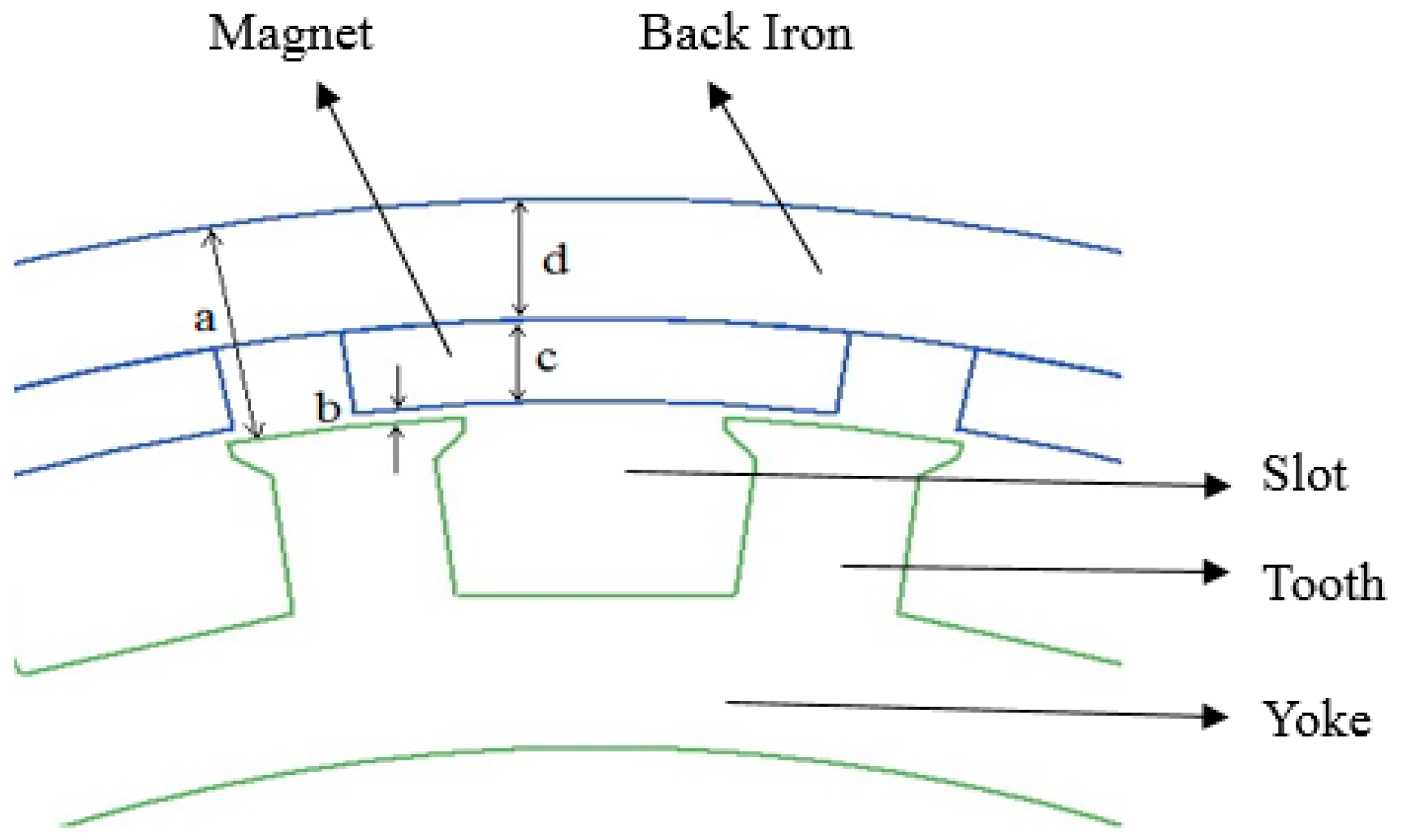
4. Essential Dimensions of In-Wheel BLDCM

The section of in-wheel BLDCM is shown in Figure 1. The dimensions are defined as air gap (b), permanent magnet (c), back iron (d) and consequently total dimension (a) is given by Equation (5).
a = b + c + d
The preliminary design parameters of the in-wheel BLDCM is listed in Table 1.
The initial geometric data and optimized data range are shown in Table 1. The first geometric data set which is presented in this study is based on a common size used for light electric vehicle motors. The designs are simulated according to the optimized data range value using ANSYS Electronics Desktop 2022 R2 as FEA solver software. To investigate the performance of electric motors, FEA is frequently employed. Computerized simulation techniques yield precise and dependable results. FEM is applied to solve Maxwell’s equations, which elucidate electromagnetic fields represented by a couple of differential equations. Researchers emphasize that the use of FEA is one of the most accurate methods, especially for calculating the power, torque and efficiency of permanent magnet motors, and for creating loaded- and no-load models for BLDCMs [39,40]. The results of FEA with analytical models for BLDCMs and PMSMs show that their consideration in the control strategy has a great impact [41].
In this paper, the investigative study with the value of the efficiency, output power, rated torque, input current, cogging torque and total weight of in-wheel BLDCM with different values for air gap (b), permanent magnet (c), and back iron (d) is shown in Table 2.

5. QFD Methodology

This study is carried out according to the flowchart given in Figure 2. The workflow of the design study can be simplified as follows: The simulation study is commenced with some preselected designs with altered dimensions. The designs are analyzed using the RMXprt electrical machine design package of ANSYS Electronics Desktop 2022 R2 software, as a general approach. The designs with promising performance are qualified. After that, the detailed FEA studies are conducted for those designs both for 2D and 3D analyses with the Maxwell package of ANSYS Electronics Desktop 2022 R2 software. Then, the decision process for selecting the best possible design is conducted by means of the proposed QFD method. The finalized design is prototyped and analyzed experimentally.
The goodness measure of desired motor performance can be shown by means of a combination of performance measures of design [39,40]. This measure is defined as quality factor of design (QFD). The radar chart of optimized performance is shown in Figure 2. The four top results and one worst result among the designs in Figure 2 are reported. Equation (6), which consists of five selected parameters, i.e., performance goodness criteria, is developed to find the quality factor of design (QFD); the equation simply represents the area of a radar chart with five different parameters,
Q F D = [ ( 1 2 ) · sin ( 2 π 5 ) ] · { [ η · ( P m m ) ] + [ ( P m m ) · ( t e i ) ] + [ ( t e i ) · ( t e m ) ] + [ ( t e m ) · ( t e t c ) ] + [ ( t e t c ) · η ] }
where QFD is the quality factor of design, η is the efficiency, Pm is the shaft power, m is the total weight, te is the rated torque, i is the input current, and tc is the cogging torque. η is an important parameter for QFD. Pm/m value represents the output power for a unit mass. te/i and te/m values show the torque produced per unit input current and the torque produced per unit mass. te/tc value indicates the torque produced for a unit cogging torque.
Therefore, Equation (7) is developed to find the quality factor of design coefficients classified by their weights. The quality factor of design (QFD) in generalized form is given as follows
Q F D = [ ( 1 2 ) · sin ( 2 π n ) ] · { k = 1 n [ γ k C k · γ k + 1 C k + 1 ] + [ γ 1 C 1 · γ n C n ] }
where C values show related goodness factors of optimized design and a coefficient can be assigned due to the concessions of related design. γ is the related weighting coefficient that determines the weighted value of the performance factor. During the design process, the value of γ can be defined between 0 and 1 according to the targeted optimum design. So, the optimum design is guided by the previously selected design constraints.
Therefore, the researchers and manufacturers of in-wheel BLDCM can determine the optimum coefficients in Equation (7) according to their design priorities. Moreover, the results of the most appropriate design can be obtained according to their objectives.

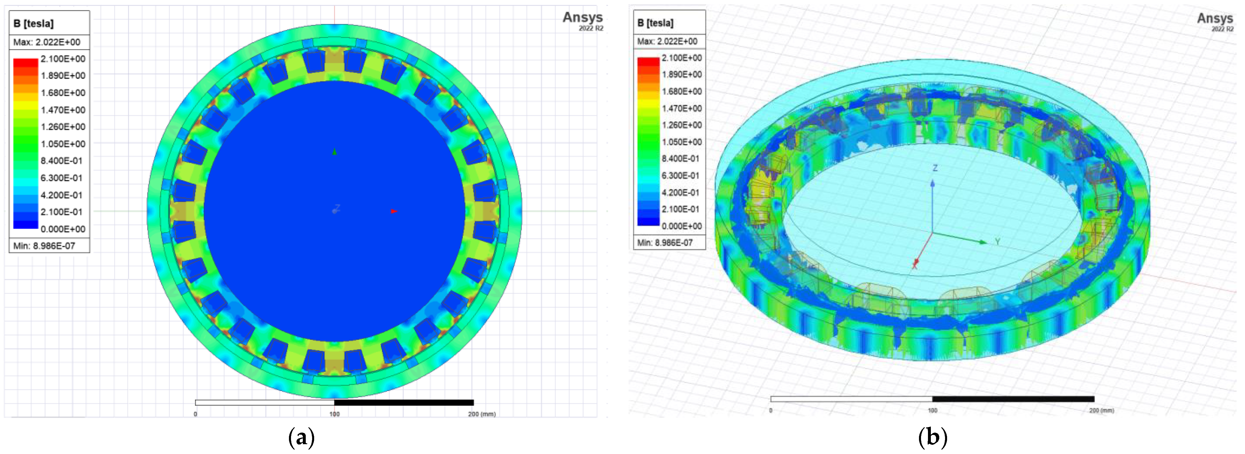
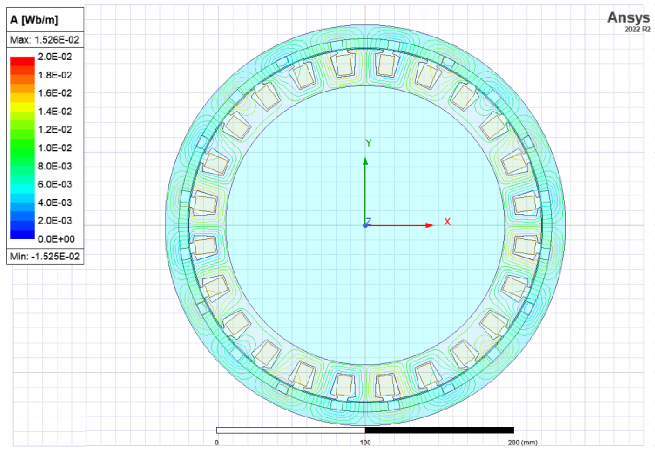
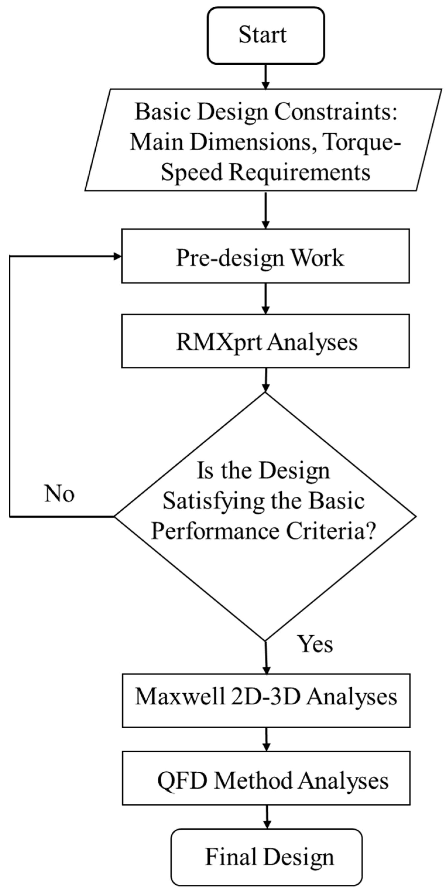
6. Analysis of In-Wheel BLDCM Performance with Different Design Parameters

The improvement of in-wheel BLDCM design for electric vehicle drive system under the condition that the main size of the motor remains constant has been revealed in recent studies.
In order to expedite the design process, a quick decision method is conceived by utilizing the correlation among rotor dimensions, magnet depth, air gap length based on previous experiences, and performance requirements.
For this study, twenty-five different design approaches have been simulated. In Table 2, the comparison of the output data of the in-wheel BLDCM is shown. During these analyses, the output power is kept constant, also the operation temperature is kept below 90 °C to avoid diminishing torque production capability due to demagnetization. Moreover, the stator slot fill factors are maintained at the range of 60–70%, which is applicable practically, and the armature current density is kept below 6 A/mm2 for natural cooling. The results of the simulations are given in Table 3.
When FEA is carried out for the optimum designed 24 slot/20 pole motor geometry, magnetic flux density and flux lines are obtained as shown in Figure 3 and Figure 4. The presented figures are showing the analyses of the final optimum design, i.e., the prototyped design.
Here, the effectiveness of employing a magnetic core is delineated by ensuring an optimal flux distribution within predefined parameters. The regions near saturation, where the flux density hovers at approximately 2 T, are conspicuously evident solely at the teeth edges. Additionally, as depicted in Figure 4, the flux lines manifest a seamless and uniform distribution, aligning with anticipated characteristics.

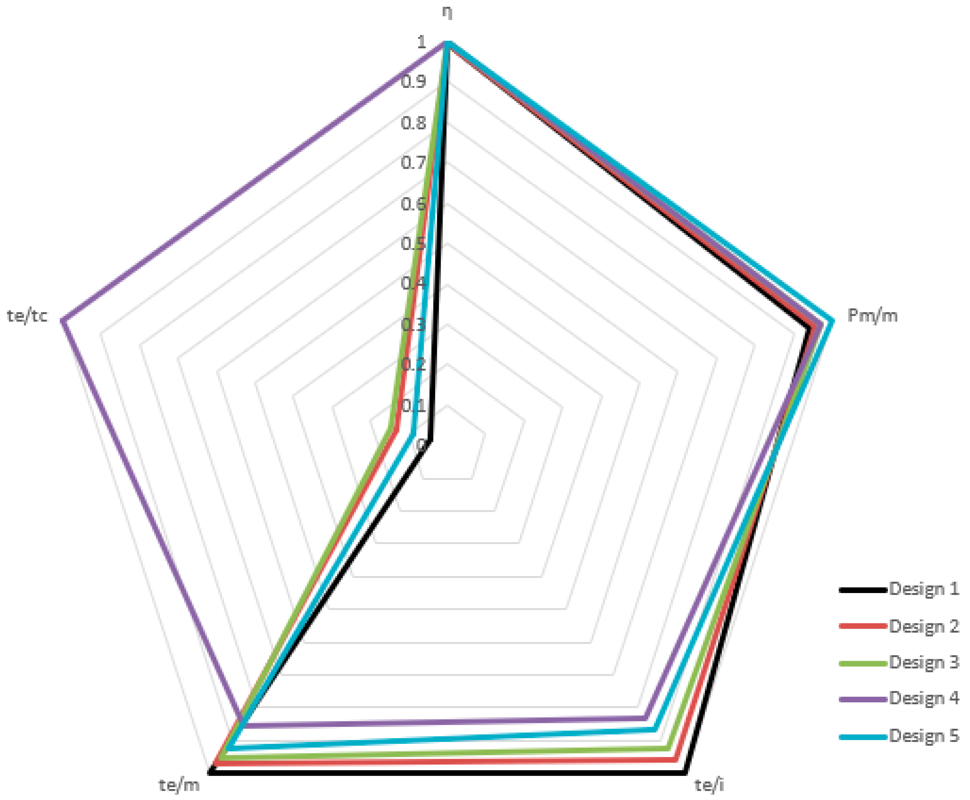
7. Implementation of QFD

After the selection of five different promising motor designs, a decision process to find the optimum design regarding the previously defined goodness criteria is implemented. As stated before, five different performance goodness factors are selected to reach the final optimal design: efficiency, cogging torque, output power-to-weight ratio, electromagnetic torque-to-terminal current ratio, and torque-to-weight ratio. All these parameters are converted to per unit values as given in Table 4 in order for the values to be comparable to each other. At the final step, Figure 5, which shows the comparison of the five different designs, is obtained.
As has been previously explained, the results of the simulations are converted into per unit values in order to be compared to each other. Based on the analysis, the design data set is converted to per unit values based on the maximum data values, and five selected designs which have resulted in the highest QFD values are given in Table 4.
As shown in Table 4, the results of the design analysis with per unit values are calculated according to QFD by using Equation (6). The comparison of the results of the quality factors among the designs from 1 to 5 is shown in Figure 5.
As a result of comparison between designs shown in Figure 5,
  • The efficiency values of all designs are almost the same.
  • The optimal result of the shaft power over the total weight belongs to Design 5.
  • The optimal result of the rated torque over the input current belongs to Design 1.
  • The optimal result of the rated torque over the total weight belongs to Design 1.
  • The optimal result of the rated torque over the cogging torque belongs to Design 4.
Design 4 comes into prominence based on QFD values among all designs. In addition, the air gap can be preferred as greater than or equal to 1 mm and less than or equal to 3 mm as shown in Figure 5. The results are obtained on the assumption that weights of all parameters in Equation (6) are per unit. As shown in Figure 5, the area of graph which is based on the quality of design parameters implies the QFD.

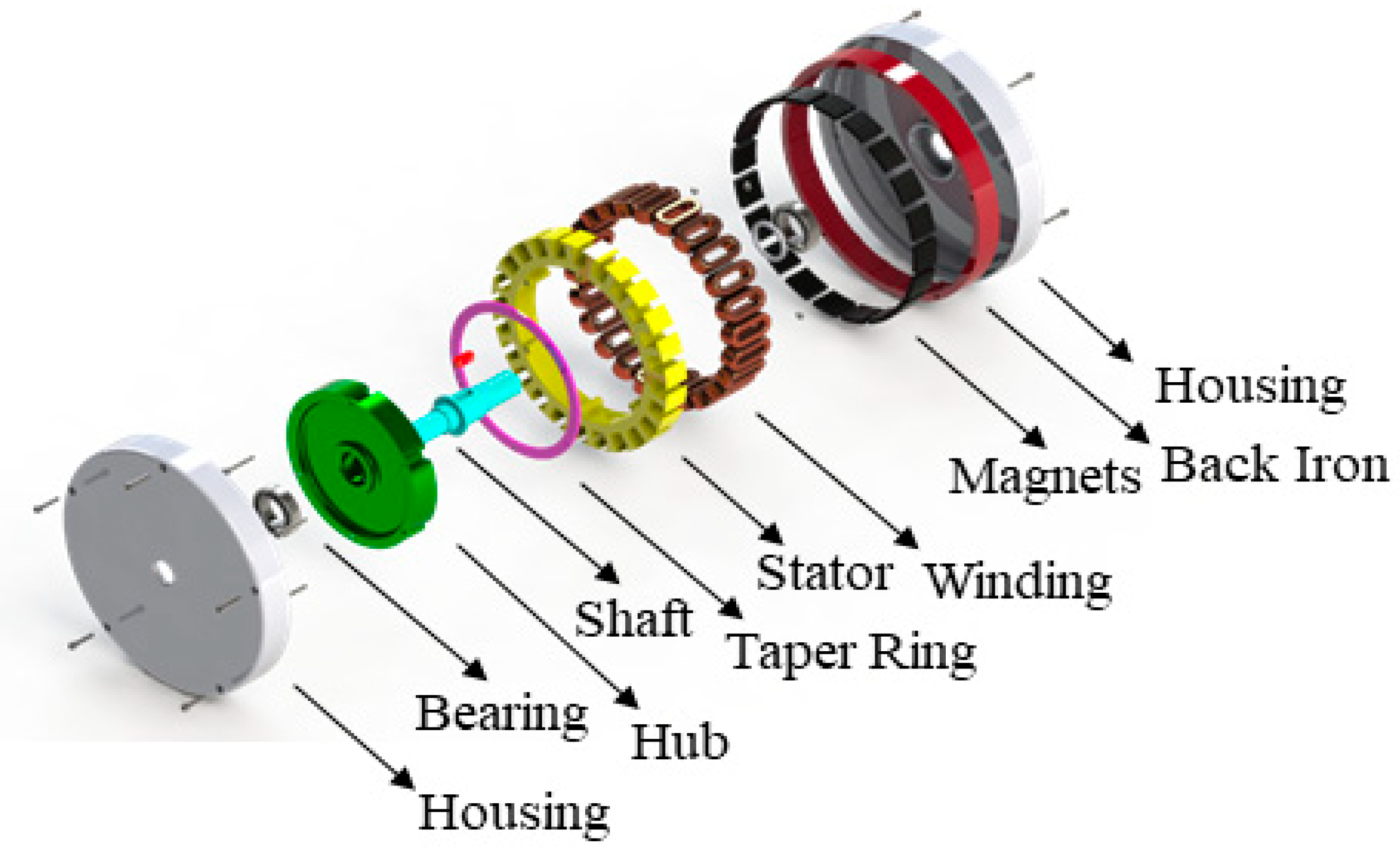
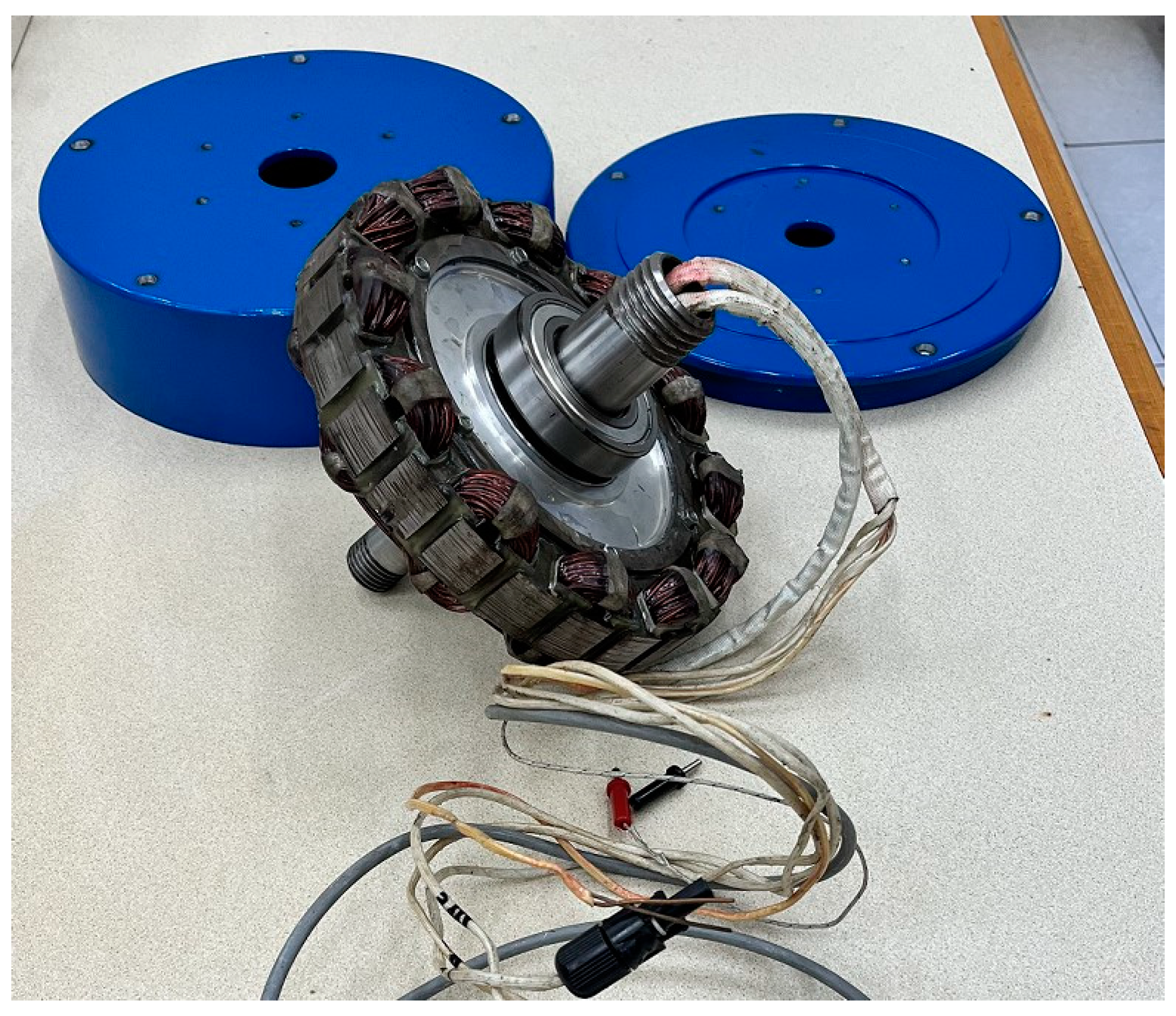
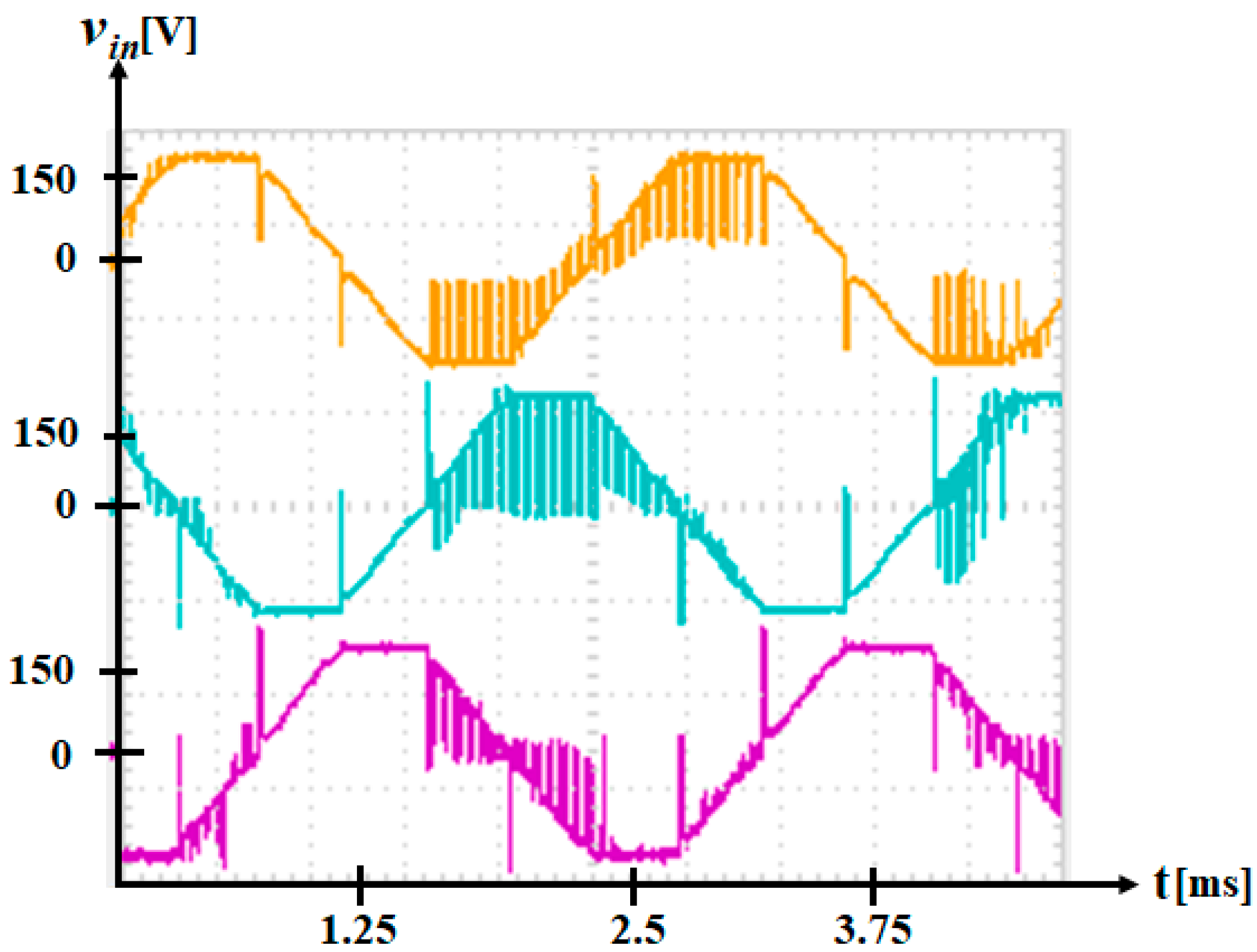
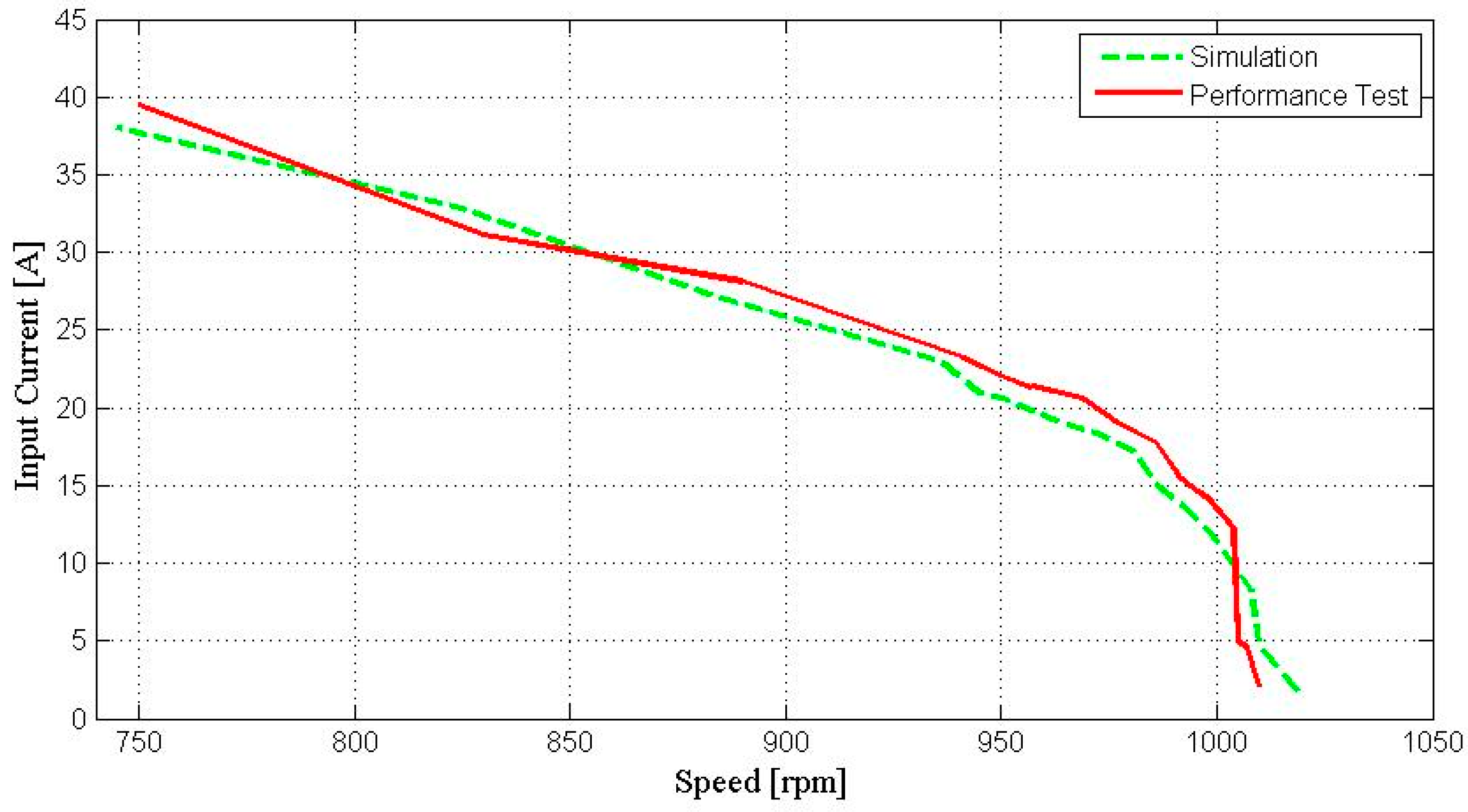
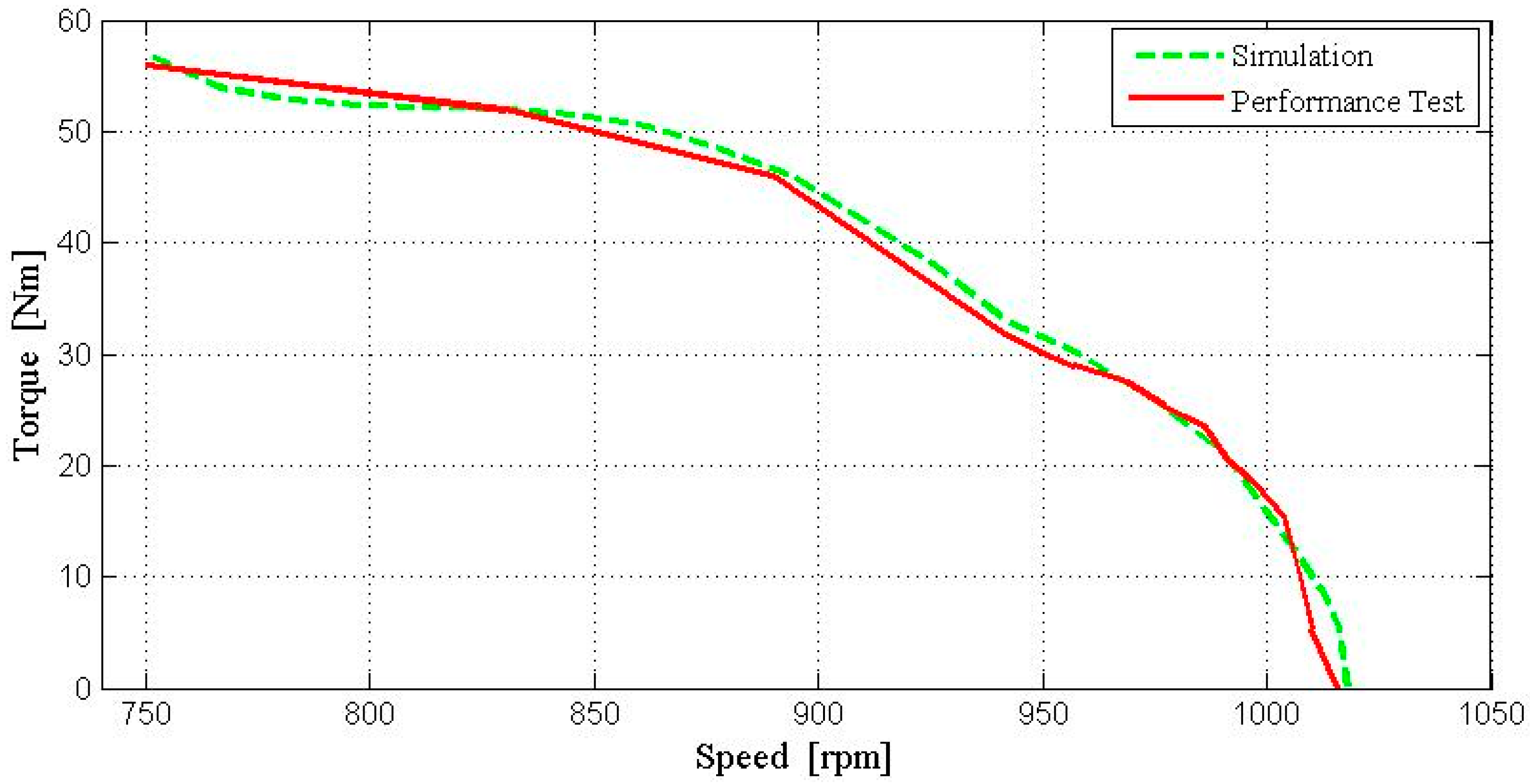
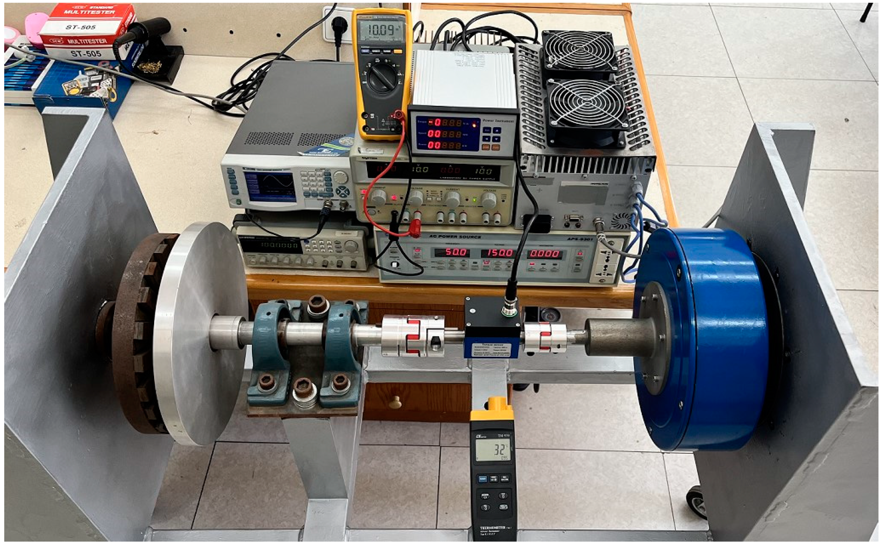
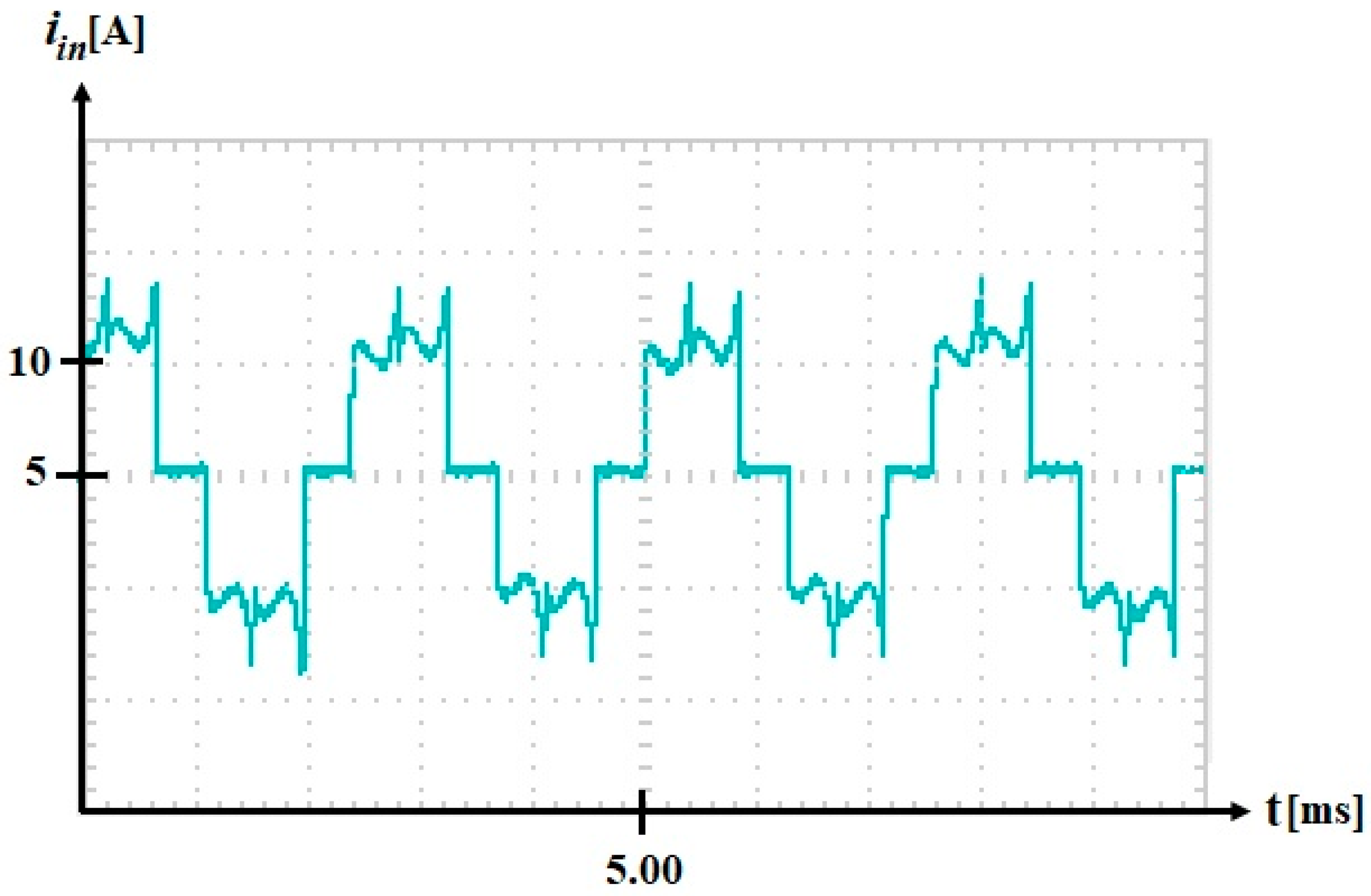
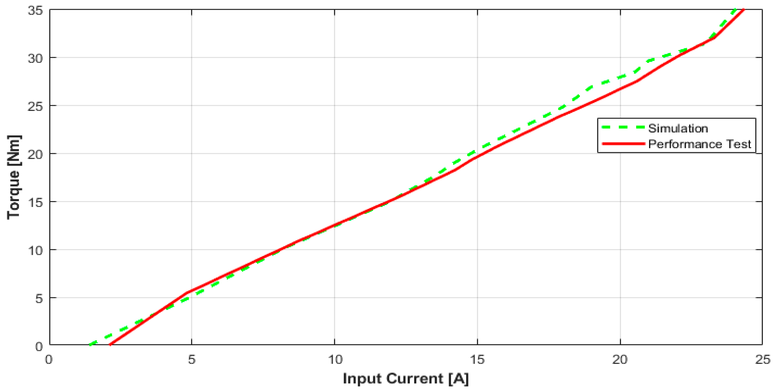
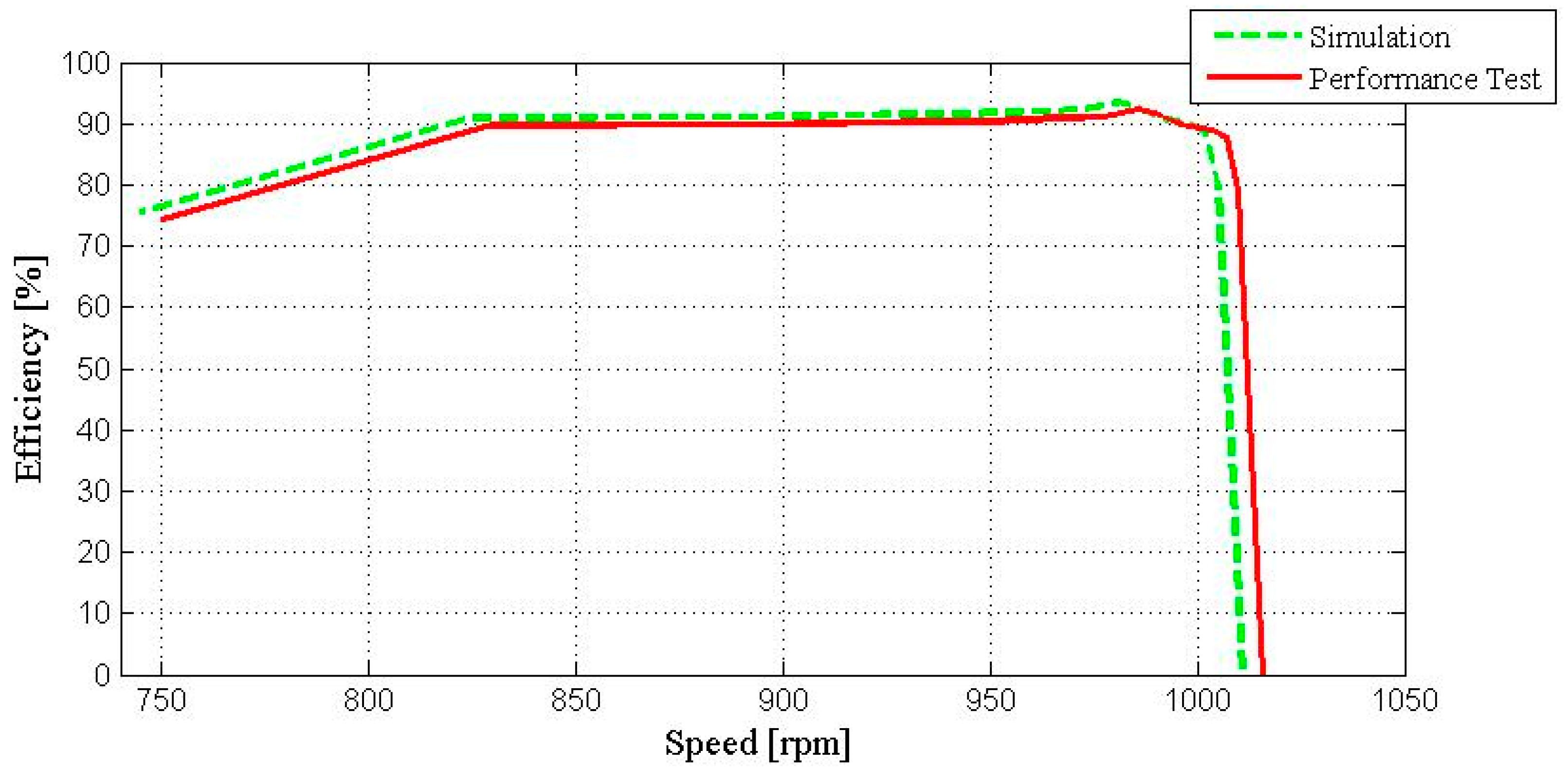
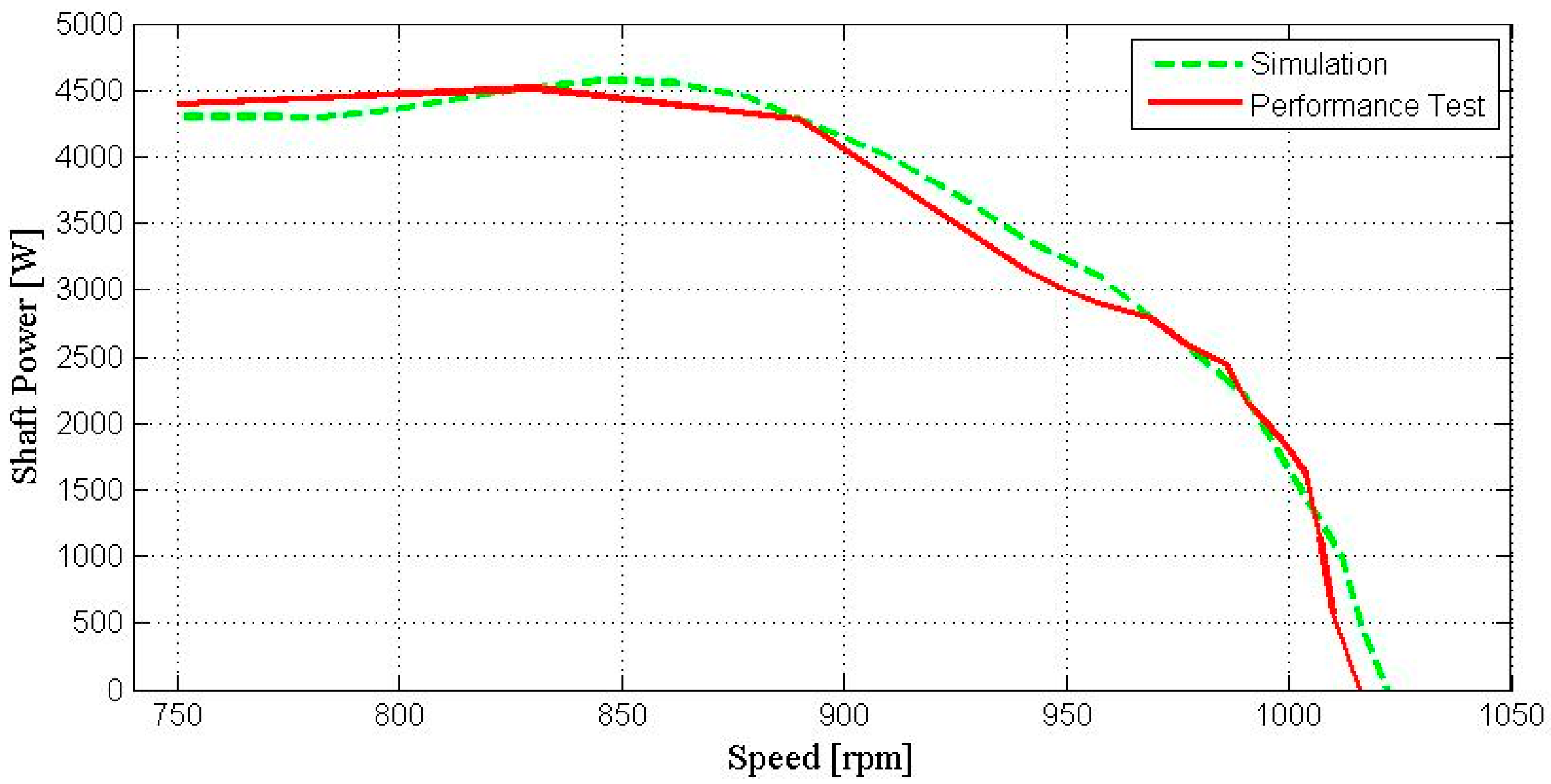
8. Prototyping and Experimental Results of In-Wheel BLDCM

After finalizing the optimum design study, the selected design, i.e., Design 4, is modelled in a SolidWorks 2022 to obtain the physical model of the motor. The exploded view of the prototype motor is shown in Figure 6. In Figure 7, the parts of the prototype motor are shown before the assembly process.
A test setup which is shown in Figure 8 is constructed to determine the performance of in-wheel BLDCM. The motor is connected to a load via a torque transducer.
The characteristics of the motor are determined by the performance of the motor under different load levels. The terminal voltage waveform for each phase and the terminal current of phase-A of the prototype motor are shown in Figure 9 and Figure 10. The terminal voltage waveforms for each phase given in Figure 9 are shown in different colors. As shown in the figures, a proper trapezoidal driving scheme, i.e., BLDC motor operation, can be seen explicitly.
The shaft power of the motor at different loads is evaluated according to the speed of the motor obtained by the tachometer and instantaneous torque values are obtained by the torque sensor placed between the load and in-wheel BLDCM in the test setup. At the same time, input power is calculated by means of the motor input current and voltage measurements. Note that these calculations are evaluated simultaneously to increase the precision of the results. As a result of the performance test, the values given in Table 5 and graphs in Figure 11, Figure 12, Figure 13, Figure 14 and Figure 15 are obtained. The simulated and tested graphs of the output torque versus terminal current are shown in Figure 11. In Figure 12, the simulated and tested characteristics of the efficiency versus shaft speed are presented. In Figure 13, the simulated and tested characteristics of the terminal current versus shaft speed are given. The shaft power versus shaft speed characteristics are shown in Figure 14 both for the simulated and experimented results. Lastly, Figure 15 depicts the shaft torque versus shaft speed graphs for the simulated and tested values. It can be seen clearly that the test results are compatible with the simulated results. In this way, the simulations are verified by the experimental work.

9. Conclusions

In this paper, an optimization approach of an in-wheel BLDCM is developed based on performance requirements and proper dimensions. A novel design decision process is introduced as quality factor of design (QFD) according to weighted performance criteria. Thus, the efficiency, output power, rated torque, input current, cogging torque and total weight of in-wheel BLDCM are evaluated by means of different values for air gap, permanent magnet depth and back iron depth. For different designs, FEM analyses are implemented. The selected optimum design is prototyped and verified experimentally. The test results are in agreement with the optimization approach.
The quality factor of design (QFD) can be used as a guide in the design of in-wheel BLDC motors for manufacturers and researchers. Through this method, the required design period and the amount of materials can be minimized compared to traditional methods.
The aim of this study also includes the provision of novel solutions to electric machine design in general. Due to the multi-parameter nature of electric machines, design studies contain numerous decision-making processes. Defining a “quality factor” in the design study therefore contributes to and consolidates the design work of electrical machinery.

Author Contributions

Conceptualization, A.S.C. and O.U.; methodology, A.S.C. and O.U.; software, A.S.C.; validation, A.S.C. and O.U.; formal analysis, A.S.C.; investigation, A.S.C. and O.U.; resources, A.S.C. and O.U.; data curation, A.S.C. and O.U.; writing—original draft preparation, A.S.C. and O.U.; writing—review and editing, A.S.C. and O.U.; visualization, A.S.C.; supervision, A.S.C.; project administration, A.S.C. All authors have read and agreed to the published version of the manuscript.

Funding

This work was supported by the Scientific and Technological Research Council of Turkey (TUBITAK) with Grant No: 121E131.

Data Availability Statement

Data are contained within the article.

Conflicts of Interest

Author Ozgur Ustun was employed by the Mekatro Mechatronic Systems R&D Company. The remaining authors declare that the research was conducted in the absence of any commercial or financial relationships that could be construed as a potential conflict of interest.

References

  1. König, P.; Sharma, D.; Konda, K.R.; Xie, T.; Höschler, K. Comprehensive Review on Cooling of Permanent Magnet Synchronous Motors and Their Qualitative Assessment for Aerospace Applications. Energies 2023, 16, 7524. [Google Scholar] [CrossRef]
  2. Huang, Z.; Wei, Q.; Xiao, X.; Xia, Y.; Rivera, M.; Wheeler, P. Enhanced Dual–Vector Model Predictive Control for PMSM Drives Using the Optimal Vector Selection Principle. Energies 2023, 16, 7482. [Google Scholar] [CrossRef]
  3. Lee, C.Y.; Hung, C.H.; Le, T.-A. Intelligent Fault Diagnosis for BLDC With Incorporating Accuracy and False Negative Rate in Feature Selection Optimization. IEEE Access 2022, 10, 69939–69949. [Google Scholar] [CrossRef]
  4. Ibrahim, B.S.K.K.; Azubir, N.A.M.; Ishak, N.H.M.; Hassan, M.K.; Toha, S.F.; Abidin, M.A.Z.; Ismail, H.F.; Zamzuri, H. PI-Fuzzy logic control for 3 phase BLDC motor for electric vehicle application. In Proceedings of the UKSim-AMSS 6th European Modelling Symposium, Valetta, Malta, 14–16 November 2012; pp. 84–88. [Google Scholar]
  5. Upadhyay, P.R.; Rajagopa, K.R.; Singh, B.P. Effect of armature reaction on the performance of an axial-field permanent magnet brushless DC motor using FE method. IEEE Trans. Magn. 2004, 40, 2023–2025. [Google Scholar] [CrossRef]
  6. Mohanraj, D.; Aruldavid, R.; Verma, R.; Sathiyasekar, K.; Barnawi, A.B.; Chokkalingam, B.; Mihet-Popa, L. A Review of BLDC Motor: State of Art, Advanced Control Techniques, and Applications. IEEE Access 2022, 10, 54833–54869. [Google Scholar] [CrossRef]
  7. Ishikawa, T.; Yonetake, K.; Kurita, N. An optimal material distribution design of Brushless DC motor by genetic algorithm considering a cluster of material. In Proceedings of the Digests of the 2010 14th Biennial IEEE Conference on Electromagnetic Field Computation, Chicago, IL, USA, 9–12 May 2010; p. 1. [Google Scholar] [CrossRef]
  8. Lakshmikanth, S.; Devarajaiah, R.M.; Chowdhury, A.; Krishna, S. Analytical Design of 3Kw BLDC Motor for Electric Vehicle Applications. In Proceedings of the 2023 3rd International Conference on Intelligent Technologies (CONIT), Hubli, India, 23–25 June 2023; pp. 1–7. [Google Scholar] [CrossRef]
  9. Cabuk, A.S. Simulation of the effect of segmented axial direction magnets on the efficiency of in-wheel permanent magnet brushless DC motors used in light electric vehicles based on finite element method. Electr Eng 2021, 103, 3111–3117. [Google Scholar] [CrossRef]
  10. Markovic, M.; Muller, V.; Hodder, A.; Perriard, Y. Optimal design of an in-wheel BLDC motor for kick scooter. In Proceedings of the 2010 IEEE Energy Conversion Congress and Exposition, Atlanta, GA, USA, 12–16 September 2010; pp. 292–296. [Google Scholar] [CrossRef]
  11. Zhu, X.; Zhao, W.; Xu, L.; Ji, J. Design and analysis of a new partitioned stator flux-modulation motor for direct drive applications. IET Electr. Power Appl. 2020, 14, 184–191. [Google Scholar] [CrossRef]
  12. Chen, M.; Chau, K.-T.; Lee, C.H.T.; Liu, C. Design and analysis of a new axial-field magnetic variable gear using pole-changing permanent magnets. Prog. Electromagn. Res. 2015, 153, 23–32. [Google Scholar] [CrossRef]
  13. Lee, C.H.T.; Chau, K.-T.; Liu, C. Electromagnetic design and analysis of magnet less double-rotor dual-mode machines. Prog. Electromagn. Res. 2013, 142, 333–351. [Google Scholar] [CrossRef]
  14. Suphama, M.; Seangwong, P.; Fernando, N.; Jongudomkarn, J.; Siritaratiwat, A.; Khunkitti, P. A Novel Asymmetric Hybrid-Layer Del-Shaped Rotor Interior Permanent Magnet Motor for Electric Vehicles. IEEE Access 2023, 12, 2793–2802. [Google Scholar] [CrossRef]
  15. Xue, F.; Liu, J. Parameter Optimization Design of PMSM. In Proceedings of the IEEE 2nd International Conference on Data Science and Computer Application (ICDSCA), Dalian, China, 28–30 October 2022; pp. 370–374. [Google Scholar] [CrossRef]
  16. Zhao, W.; Chen, D.; Lipo, T.A.; Kwon, B.I. Performance Improvement of Ferrite-Assisted Synchronous Reluctance Machines Using Asymmetrical Rotor Configurations. IEEE Trans. Magn. 2015, 51, 1–4. [Google Scholar] [CrossRef]
  17. Patel, S.S.; Botre, B.A.; Krishan, K.; Kaushal, K.; Samarth, S.; Akbar, S.A.; Biradar, Y.; Prabhu, K.R. Modeling and implementation of intelligent commutation system for BLDC motor in underwater robotic applications. In Proceedings of the 2016 IEEE 1st International Conference on Power Electronics, Intelligent Control and Energy Systems (ICPEICES), Delhi, India, 4–6 July 2016; pp. 1–4. [Google Scholar] [CrossRef]
  18. Xu, C.; Wang, D.; Xu, G.; Wang, X. Design and Comparison of the Centralized Winding Permanent Magnet Motors for Robotic Joint. In Proceedings of the 26th International Conference on Electrical Machines and Systems (ICEMS), Zhuhai, China, 5–8 November 2023; pp. 5317–5321. [Google Scholar] [CrossRef]
  19. Rohman, F.; Nurhadi; Martawati, M.E. Wireless Enabled Brushless DC Motor Controller for Robotic Application. In Proceedings of the 2021 International Conference on Electrical and Information Technology (IEIT), Malang, Indonesia, 14–15 September 2021; pp. 217–222. [Google Scholar] [CrossRef]
  20. Pindoriya, R.M.; Mishra, A.K.; Rajpurohit, B.S.; Kumar, R. An Analysis of Vibration and Acoustic Noise of BLDC Motor Drive. In Proceedings of the 2018 IEEE Power & Energy Society General Meeting (PESGM), Portland, OR, USA, 5–10 August 2018; pp. 1–5. [Google Scholar] [CrossRef]
  21. Kang, G.H.; An, Y.G.; Kim, G.T. The Characteristics of Noise and Vibration by Asymmetrical Overhang Effect of Permanent Magnet in BLDC Motor. In Proceedings of the 12th Biennial IEEE Conference on Electromagnetic Field Computation, Miami, FL, USA, 30 April–3 May 2006; p. 493. [Google Scholar] [CrossRef]
  22. Saed, N.; Asgari, S.; Muetze, A. On the Effect of Claw Geometry on the Vibration of Single-Phase Claw-Pole BLDC Machines. In Proceedings of the 11th International Conference on Power Electronics and ECCE Asia (ICPE 2023-ECCE Asia), Jeju Island, Republic of Korea, 22–25 May 2023; pp. 142–147. [Google Scholar] [CrossRef]
  23. Jiang, C.; Habetler, T.G. Static eccentricity fault detection of the BLDC motor inside the air handler unit (AHU). In Proceedings of the 2015 IEEE International Electric Machines & Drives Conference (IEMDC), Coeur d’Alene, ID, USA, 10–13 May 2015; pp. 1473–1476. [Google Scholar] [CrossRef]
  24. Chai, F.; Zhu, J.; Zhao, K.; Pei, Y.; Chen, T. Magnetic Field Analysis of Conical Shape External Rotor Permanent Magnet Synchronous Motor Based on Equivalent Magnetic Network Method. In Proceedings of the 26th International Conference on Electrical Machines and Systems (ICEMS), Zhuhai, China, 5–8 November 2023; pp. 4168–4173. [Google Scholar] [CrossRef]
  25. Kim, T.H.; Choi, J.; Ko, K.C.; Lee, J. Finite-element analysis of brushless DC motor considering freewheeling diodes and DC link voltage ripple. IEEE Trans. Magn. 2003, 39, 3274–3276. [Google Scholar] [CrossRef]
  26. Vishwakarma, V.K.; Rao, G.; Landge, B. Design of BLDC Based ISG for Aerial Application: Effect of Stator Slot Design Parameters on the Efficiency. In Proceedings of the 2018 International Conference on Advances in Communication and Computing Technology (ICACCT), Sangamner, India, 8–9 February 2018; pp. 23–28. [Google Scholar] [CrossRef]
  27. Yoo, J.S.; Lee, G.S.; Jang, H.; Cho, S.; Seo, J.H.; Bae, S.W.; Lee, H.-J.; Lee, G.Y.; Lee, J. Analysis of Optimize Designing Small Size BLDC Motor Considering Air Gap Clearance. In Proceedings of the 2018 21st International Conference on Electrical Machines and Systems (ICEMS), Jeju, Republic of Korea, 7–10 October 2018; pp. 265–268. [Google Scholar] [CrossRef]
  28. Meng, G.; Li, H.; Xiong, H. Calculation of gig air-gap magnetic field in poly-phase multi-pole BLDC motor. In Proceedings of the 2008 International Conference on Electrical Machines and Systems, Wuhan, China, 17–20 October 2008; pp. 3224–3227. [Google Scholar]
  29. Sangsefidi, Y.; Ziaeinejad, S.; Shoulaie, A. Torque ripple reduction of BLDC motors by modifying the non-commutating phase voltage. In Proceedings of the International Conference on Electrical, Control and Computer Engineering 2011 (InECCE), Kuantan, Malaysia, 21–22 June 2011; pp. 308–312. [Google Scholar] [CrossRef]
  30. Banović, M.; Iričanin, B.; Reljić, D.; Jerkan, D. Hybrid Iron Loss Model for IPMSMs in Wide-Speed Range Applications. In Proceedings of the 22nd International Symposium on Power Electronics (Ee), Novi Sad, Serbia, 25–28 October 2023; pp. 01–06. [Google Scholar] [CrossRef]
  31. Zheng, P.; Liu, Y.; Wang, T.; Cheng, S. Pole optimization of brushless DC motor. In Proceedings of the Conference Record of the 2004 IEEE Industry Applications Conference, 2004. 39th IAS Annual Meeting, Seattle, WA, USA, 3–7 October 2004; Volume 2, pp. 1062–1067. [Google Scholar] [CrossRef]
  32. Abirami, S.; Bala, S.M.; Priya, R.J. Design of BLDC Hub Motor using FEM analysis. In Proceedings of the 2014 International Conference on Green Computing Communication and Electrical Engineering (ICGCCEE), Coimbatore, India, 6–8 March 2014; pp. 1–6. [Google Scholar] [CrossRef]
  33. Phyu, H.N.; Quan, J. Analysis of rotor eddy current loss with different magnetization directions in PM BLDC motor. In Proceedings of the 18th International Conference on Electrical Machines and Systems (ICEMS), Pattaya, Thailand, 25–28 October 2015; pp. 1170–1175. [Google Scholar] [CrossRef]
  34. Cros, J.; Viarouge, P. Synthesis of high-performance PM motors with concentrated windings. IEEE Trans. Energy Convers. 2002, 17, 248–253. [Google Scholar] [CrossRef]
  35. Zhu, Z.Q.; Xia, Z.P.; Wu, L.J.; Jewell, G.W. Influence of slot and pole number combination on radial force and vibration modes in fractional slot pm brushless machines having single- and double-layer windings. In Proceedings of the IEEE Energy Conversion Congress and Exposition, San Jose, CA, USA, 20–24 September 2009; pp. 3443–3450. [Google Scholar]
  36. Friendly, M.; Andrews, R.J. The radiant diagrams of Florence Nightingale. SORT-Stat. Oper. Res. Trans. 2021, 45, 3–18. [Google Scholar] [CrossRef]
  37. Laithwaite, E.R. The goodness of a machine. Proc. Inst. Electr. Eng. 1965, 112, 538–541. [Google Scholar] [CrossRef]
  38. Hendershot, J.R.; Miller, T.J.E. Design of Brushless Permanent-Magnet Machines, 2nd ed.; Motor Design Books LLC: Miami Beach, FL, USA, 2010. [Google Scholar]
  39. Nasiri-Zarandi, R.; Karami-Shahnani, A.; Toulabi, M.S.; Tessarolo, A. Design and Experimental Performance Assessment of an Outer Rotor PM-Assisted SynRM for the Electric Bike Propulsion. IEEE Trans. Transp. Electrif. 2023, 9, 727–736. [Google Scholar] [CrossRef]
  40. Tripathi, S.; Gumma, M.; Potarlanka, S.R. Virtual design optimization of a BLDC motor for a two wheeler electric cargo vehicle. In Proceedings of the 2nd Asian Conference on Innovation in Technology (ASIANCON), Ravet, India, 26–28 August 2022; pp. 1–6. [Google Scholar] [CrossRef]
  41. Bitencourt, A.; Borba, B.; França, B.; Dias, D. Development and Analysis of an IPMSM Fea-Based Model for Electric Vehicle Application. In Proceedings of the 25th European Conference on Power Electronics and Applications (EPE’23 ECCE Europe), Aalborg, Denmark, 4–8 September 2023; pp. 1–10. [Google Scholar] [CrossRef]
Figure 1. Part of in-wheel BLDCM.
Energies 17 01106 g001
Figure 2. Design flowchart.
Energies 17 01106 g002
Figure 3. Distribution of magnetic flux density of in-wheel BLDCM: (a) 2D and (b) 3D.
Energies 17 01106 g003
Figure 4. Magnetic flux lines of in-wheel BLDCM.
Energies 17 01106 g004
Figure 5. Radar charts for qualified designs.
Energies 17 01106 g005
Figure 6. Exploded view of prototype motor.
Energies 17 01106 g006
Figure 7. Prototype of in-wheel PMSM.
Energies 17 01106 g007
Figure 8. Test setup.
Energies 17 01106 g008
Figure 9. The 3-phase terminal voltage waveforms.
Energies 17 01106 g009
Figure 10. Phase current.
Energies 17 01106 g010
Figure 11. Shaft torque versus terminal current characteristics.
Energies 17 01106 g011
Figure 12. Efficiency versus shaft speed characteristics (simulated and tested).
Energies 17 01106 g012
Figure 13. Terminal current versus shaft speed characteristics (simulated and tested).
Energies 17 01106 g013
Figure 14. Shaft power versus shaft speed characteristics (simulated and tested).
Energies 17 01106 g014
Figure 15. Shaft torque versus shaft speed characteristic (simulated and tested).
Energies 17 01106 g015
Table 1. Specifications of analysis motor.
ParameterValueUnit
Rated Output Power2.5kW
Rated Voltage150V
Number of Poles20
Number of Stator Slots24
Given Rated Speed900rpm
Type of SteelM15_29G
Length of Rotor30mm
Type of MagnetNdFe38
Outer Diameter of Stator234mm
Outer Diameter of Rotor265.8mm
Electrical Pole Embrace0.792mm
Table 2. Initial and optimized geometric data.
Data NameInitial Data
[mm]
Optimized Data Range
[mm]
Min–Max
Increment Step
[mm]
a15.915.9fixed
b11–30.5
c33–71
d11.95.9–11.90.5 or 1.0 *
* Increase in b causes an increment value of 0.5; an increase in c causes an increment value of 1.0.
Table 3. Design analysis results.
Full Load DataDesign 1Design 2Design 3Design 4Design 5
η [%]94.928195.034195.118495.356895.2557
Pm [W]2499.912499.82499.742499.982499.99
te [Nm]22.057321.104320.356918.248919.1299
i [A]17.556517.536117.520217.478117.4967
tc [Nm]0.667040.220580.188300.025160.29259
m [kg]5.630045.545675.460945.44965.29044
Table 4. Analysis results with normalized values.
Full Load DataDesign 1Design 2Design 3Design 4Design 5
η0.99550430.99661590.997499910.9989398
Pm/m0.93965060.95390420.96868140.97079031
te/i10.95790730.92482190.83105170.8702461
te/m10.97135080.95148820.85473450.9229541
te/tc0.04559050.13191030.149051110.0901421
QFD1.41047991.45253401.44211322.06509911.3532123
Table 5. Results of performance test.
Test
Number
Input Current
[A]
Input Voltage
[V]
Speed
[min−1]
Rated Torque
[Nm]
Input Power
[W]
Shaft Power
[W]
Efficiency
[%]
14.8150.310105.4721.44571.1079.16
212.3148.9100415.51831.471629.5388.97
314.8150.299519.32222.962010.8490.46
417.8148.898623.72648.642446.9392.38
520.6148.896927.53065.282790.3191.03
622.1150.295030.23319.423004.1990.50
Disclaimer/Publisher’s Note: The statements, opinions and data contained in all publications are solely those of the individual author(s) and contributor(s) and not of MDPI and/or the editor(s). MDPI and/or the editor(s) disclaim responsibility for any injury to people or property resulting from any ideas, methods, instructions or products referred to in the content.

