Experimental Study of the Dynamic Water–Gas Ratio of Water and Gas Flooding in Low-Permeability Reservoirs

Abstract
1. Introduction
2. Experimental Preparation
2.1. Experimental Materials
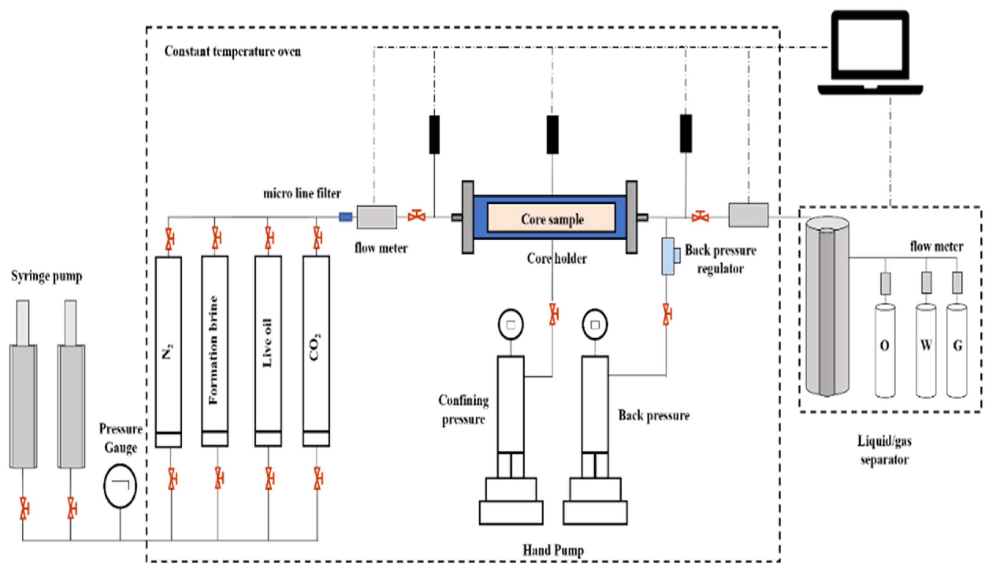
2.2. Experimental Setup
2.3. Experimental Cases
- (1)
- The core was placed in the core clamp using the Huppler standard, and then the no-leakage test was carried out. The pore volume and porosity were measured using the imbibition method, and the permeability was tested by injecting saline water with different flow rates. The permeability was calculated according to Darcy’s law.
- (2)
- After the core cleaning, leakage test, and saturated oil preparation, three types of tests were carried out: continuous gas flooding, WAG flooding with a fixed water–gas ratio, and WAG flooding with a dynamic water–gas ratio.
- (1)
- The pore volume and porosity were measured using the imbibition method, and the core permeability was tested by injecting saline water with different flow rates. Then, the core was saturated with formation water and the water permeability was measured.
- (2)
- The oil was saturated with simulated oil, bound water was created, and the oil permeability under bound water was measured.
- (3)
- The flooding fluid was injected into the core plug at a constant flow rate of 10 mL/h, and the pressure at the outlet end was maintained at 20 MPa. The oil flooding experiment was carried out according to the design standard.
- Elastic development, water flooding with a water content of 30%, or gas flooding with gas after turning to continuous gas flooding (core numbers 1, 4, 7)—after saturating the formation crude oil at 90 °C and 20 MPa, continuous gas flooding was carried out for displacement.
- Elastic development, water flooding with a water content of 30%, or gas flooding with gas after turning to WAG driving (core numbers 2, 5, 8)—after saturating the formation crude oil at 90 °C and 20 MPa, WAG1:1 (0.1 HCPV injected water + 0.1 HCPV injected gas) was carried out for displacement.
- WAG flooding after elastic development, water flooding with water cut of 30%, or the appearance of gas flooding with gas (core numbers 3, 6, 9)—after saturating the formation crude oil at 90 °C and 20 MPa, WAG1:2 (0.1 HCPV water injected + 0.2 HCPV gas injected) for three cycles and then WAG2:1 (0.2 HCPV water injected + 0.1 HCPV gas injected) for three cycles were conducted for displacement.
3. Experimental Results
3.1. Experimental Results of Different Displacement Methods after Elastic Development
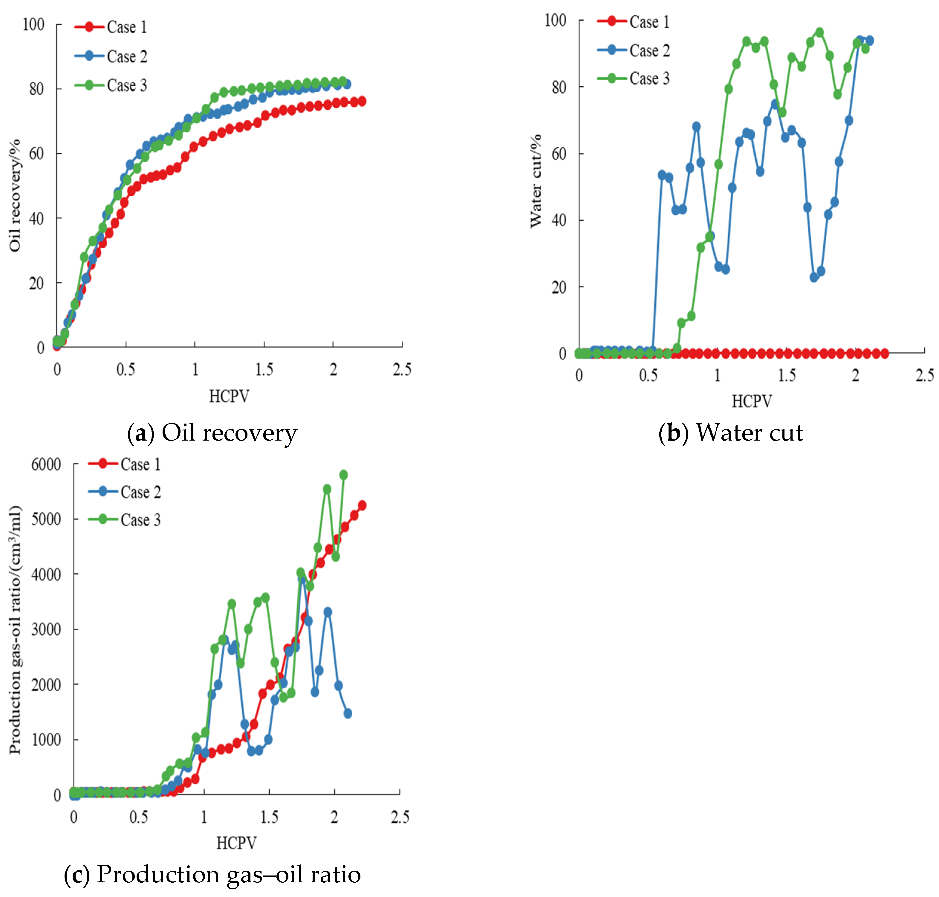
- (1)
- As shown in Figure 2a, the oil recovery of WAG flooding after elastic development is significantly higher than that of continuous gas flooding. In addition, there is not much difference between the oil recovery of WAG flooding with fixed and dynamic water–gas ratios. This indicates that the formation energy decreases more after elastic development, and WAG flooding is more effective in supplementing the formation energy compared with continuous gas flooding.
- (2)
- As shown in Figure 2b, there is no original formation water production in continuous gas flooding after elastic development, and there is injected water production in WAG flooding. Specifically, WAG flooding with a fixed water–gas ratio produces water earlier than that with a dynamic water–gas ratio, but the water cut of the latter rises faster, which is consistent with the similarity in the water–gas ratios of both WAG flooding methods.
- (3)
- As shown in Figure 2c, after elastic development, WAG flooding with a dynamic water–gas ratio produces gas the earliest. There is also a greater and increasing fluctuation in the production gas–oil ratio. WAG flooding with a fixed water–gas ratio produces gas later, and there is a small production gas–oil ratio that rises in a wavelike manner. Continuous gas flooding produces gas the latest, but the production gas–oil ratio increases fastest and almost linearly after producing the gas.
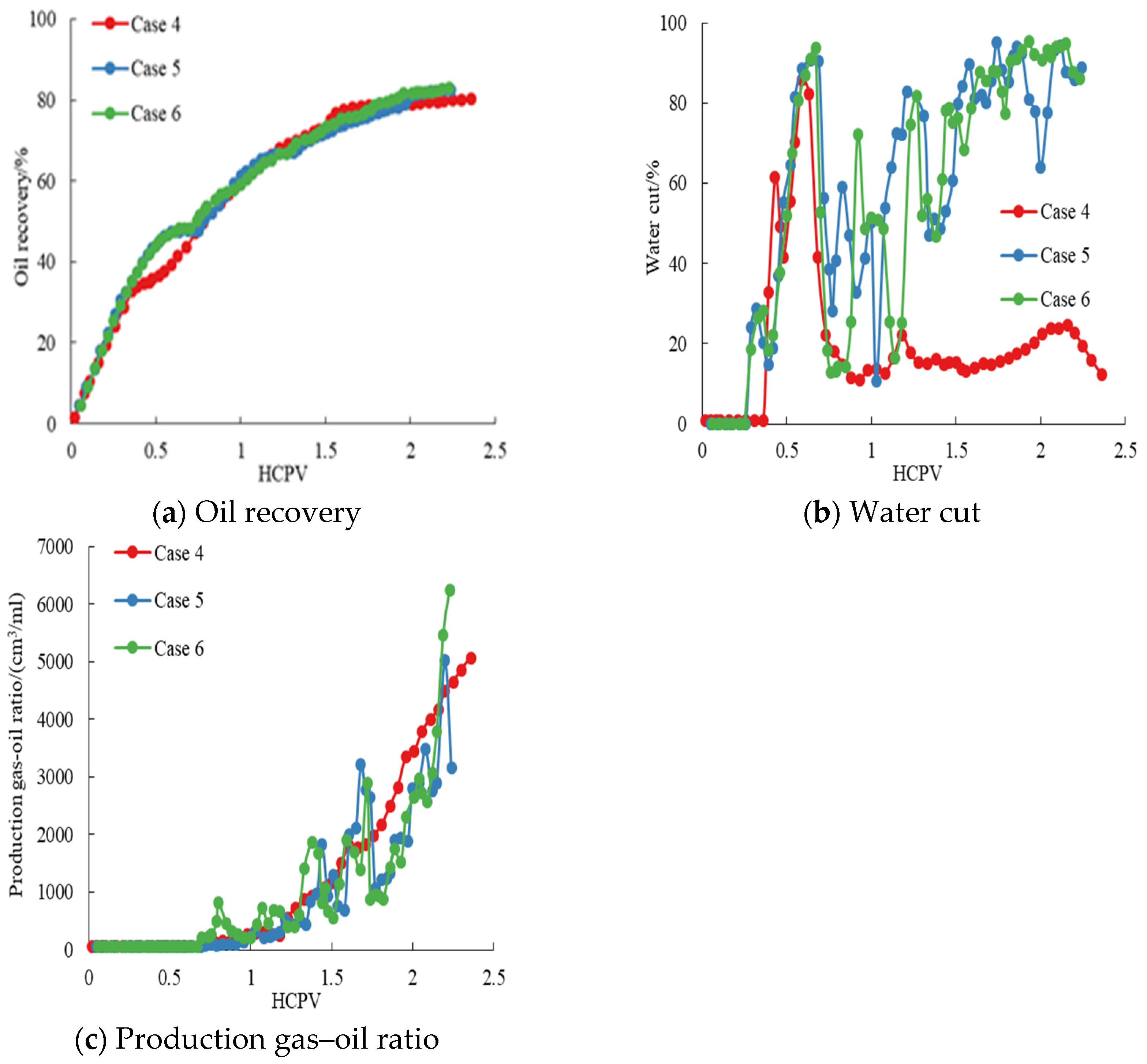
3.2. Experimental Results of Different Displacement Methods after Water Flooding
- (1)
- As shown in Figure 3a, the oil recovery of WAG flooding after water flooding is slightly higher than that of continuous gas flooding, and the difference between the oil recovery of WAG flooding with fixed and dynamic water–gas ratios is very small. This indicates that the formation energy is maintained well after water flooding development, and the effect of WAG and continuous gas flooding in supplementing the formation energy is comparable.
- (2)
- As shown in Figure 3b, the water cut is higher in the early stage of continuous gas flooding after water flooding when the injected water is replaced, and the water cut decreases significantly in the late stage of continuous gas flooding due to the absence of an injected water replenishment. The difference in the water cut change law between WAG flooding with fixed and dynamic water–gas ratios is relatively small.
- (3)
- As shown in Figure 3c, WAG flooding with a dynamic water–gas ratio produces gas the earliest after water flooding, followed by continuous gas flooding and then WAG flooding with a fixed water–gas ratio. The production gas–oil ratio steadily rises after continuous gas flooding while producing gas, and the production gas–oil ratio increases in a wavelike manner after WAG flooding. The change rule of the production gas–oil ratio of the two kinds of WAG flooding is the same. Until the end of development, there is not much difference in the production gas–oil ratio corresponding to different flooding methods.
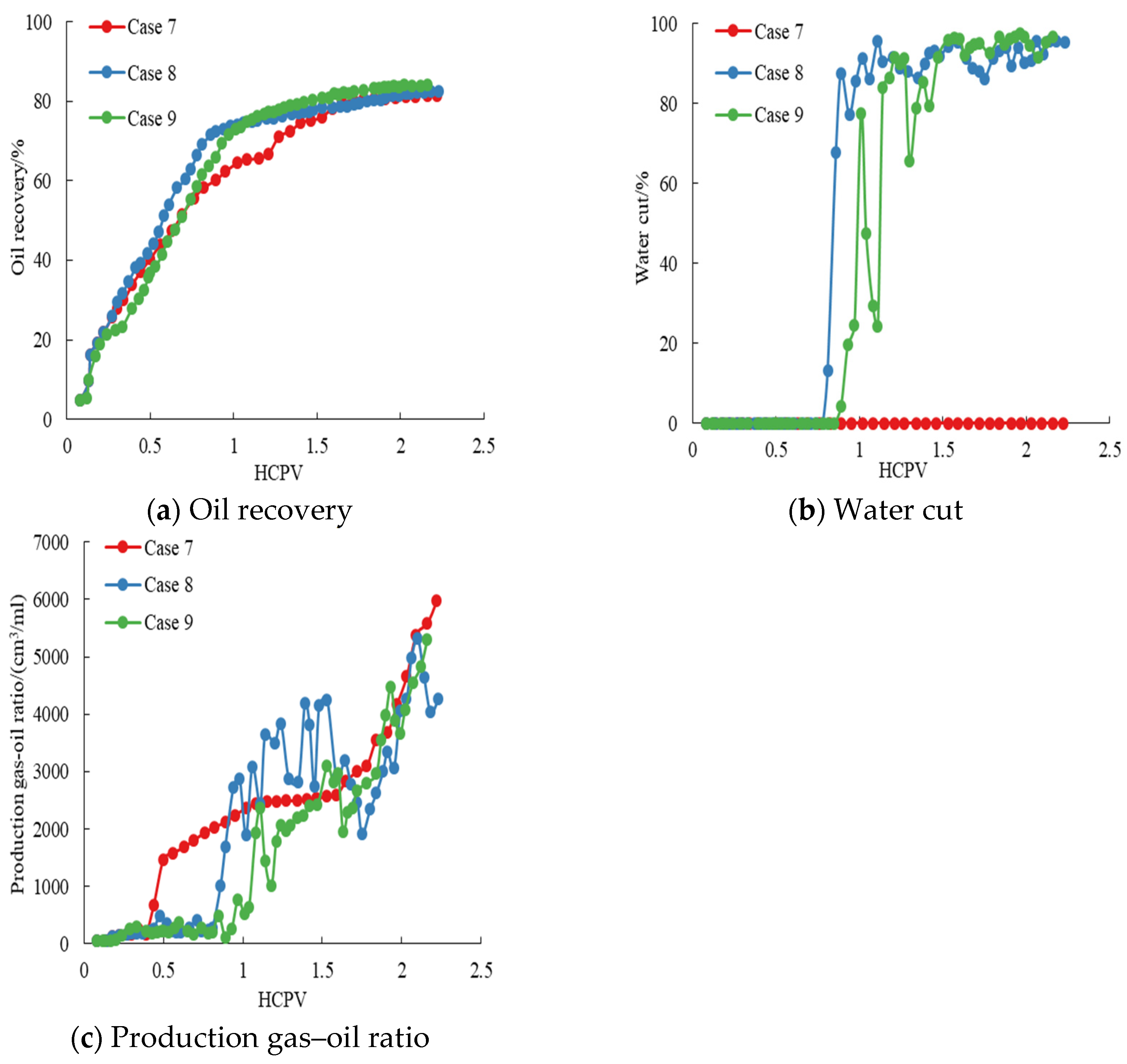
3.3. Experimental Results of Different Displacement Methods after Gas Flooding
- (1)
- As shown in Figure 4a, the oil recovery of WAG flooding with a dynamic water–gas ratio after gas flooding is slightly higher than that of WAG flooding with a fixed water–gas ratio and continuous gas flooding. This indicates that the formation energy is maintained better after a gas flooding development, but WAG flooding with a dynamic water–gas ratio is more effective in replenishing the formation energy.
- (2)
- As shown in Figure 4b, there is no original formation water production after continuous gas flooding, and there is injected water production in WAG flooding. WAG flooding with a fixed water–gas ratio produces water earlier, and the water cut rises faster. WAG flooding with a dynamic water–gas ratio produces water later, but the final water cut is comparable to WAG flooding with a fixed water–gas ratio.
- (3)
- As shown in Figure 4c, continuous gas flooding produces gas earliest after gas flooding, followed by WAG flooding with a fixed water–gas ratio and that with a dynamic water–gas ratio. After producing the gas, the production gas–oil ratios of the three development types all show a slower increase in the early stage and a faster increase in the later stage. However, the production gas–oil ratio of continuous gas flooding is larger than that of WAG flooding, and the production gas–oil ratio of WAG flooding with a fixed water–gas ratio is larger than that of WAG flooding with a dynamic water–gas ratio.
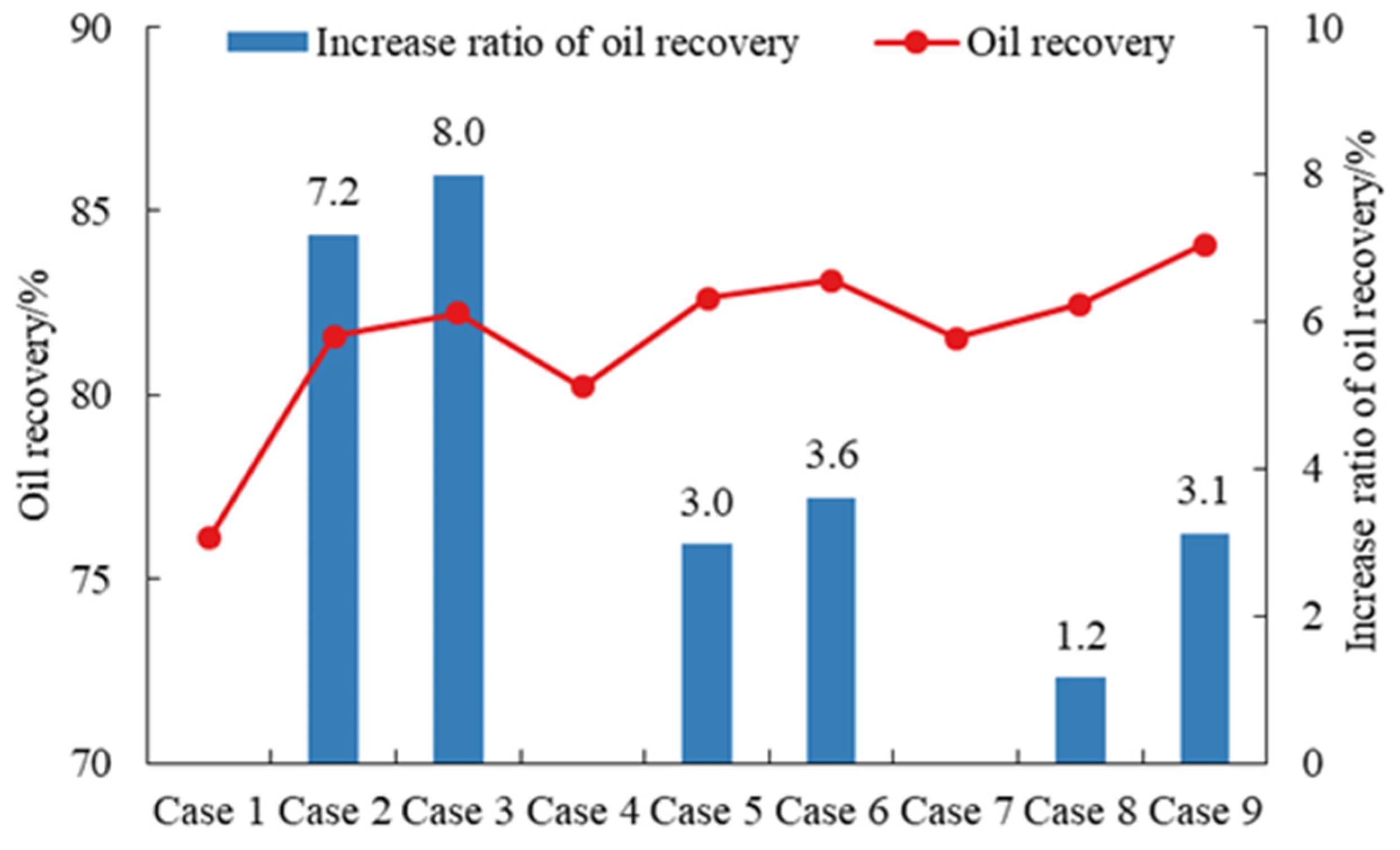
4. Experimental Data Analysis
5. Conclusions
- (1)
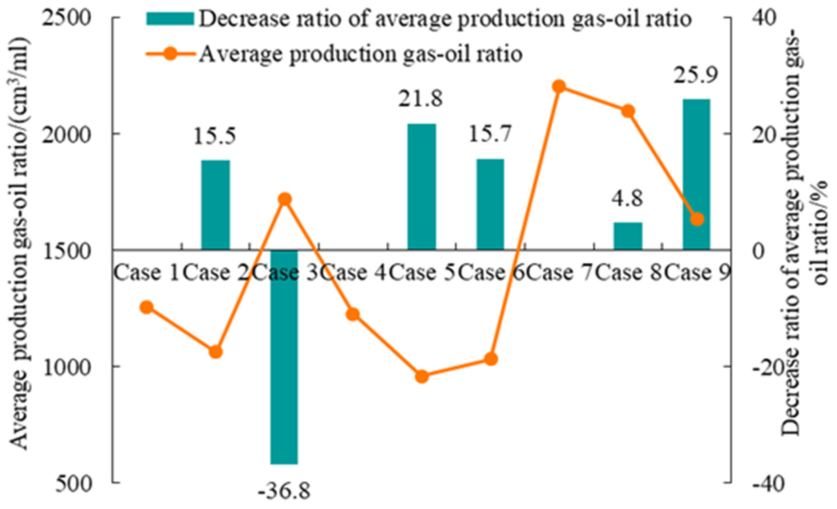
- WAG (alternating water and gas injection) flooding is a CO2-enhanced oil recovery (EOR) displacement technology that has been intensively developed in terms of research and application nationally and internationally in recent years. In this study, the development effect of different displacement methods was investigated through long-core displacement experiments in low-permeability reservoirs. Using the oil recovery and average production gas–oil ratio in the development stage as the main evaluation indexes, we compared the development effects of different subsequent developments (WAG flooding with a dynamic water–gas ratio, WAG flooding with a fixed water–gas ratio, continuous gas flooding), with the early development methods such as elastic development, water flooding, and gas flooding. The experimental results show that WAG flooding is better than continuous gas flooding, but the effect of the WAG flooding development depends on the early development method.
- (2)
- The feasibility and applicability of the dynamic design of WAG flooding were clarified based on the results of an experimental analysis. The recommendations for the water–gas ratio design of WAG flooding are as follows: when the early stage is elastic development, the dynamic water–gas ratio is not conducive to the control of the rise in the water cut and gas channeling, so it is more suitable to use the fixed water–gas ratio. When the early stage is water flooding, the oil recovery of the dynamic water–gas ratio is higher, so the use of the dynamic water–gas ratio is recommended. When the early stage is gas flooding, the development effect of the dynamic water–gas ratio is significantly better than that with the fixed water–gas ratio; therefore, the use of the dynamic water–gas ratio is recommended. This has important practical significance for further improving the development effect of WAG flooding in low-permeability reservoirs.
Author Contributions
Funding
Data Availability Statement
Conflicts of Interest
References
- Afzali, S.; Rezaei, N.; Zendehboudi, S. A comprehensive review on enhanced oil recovery by water alternating gas (WAG) injection. Fuel 2018, 227, 218–246. [Google Scholar] [CrossRef]
- Massarweh, O.; Abushaikha, A.S. A review of recent developments in CO2 mobility control in enhanced oil recovery. Petroleum 2022, 8, 291–317. [Google Scholar] [CrossRef]
- Kang, W.-L.; Zhou, B.-B.; Issakhov, M.; Gabdullin, M. Advances in enhanced oil recovery technologies for low permeability reservoirs. Pet. Sci. 2022, 19, 1622–1640. [Google Scholar] [CrossRef]
- Cao, C.; Song, Z.; Su, S.; Tang, Z.; Xie, Z.; Chang, X.; Shen, P. Water-based nanofluid-alternating-CO2 injection for enhancing heavy oil recovery: Considering oil-nanofluid emulsification. J. Pet. Sci. Eng. 2021, 205, 108934. [Google Scholar] [CrossRef]
- dos Santos Bastos, L.; da Silva Lins, I.E.; e Rosa, P.D.T.V.; Costa, G.M.N.; de Melo, S.A.B.V. An experimental assessment of seawater alternating near-miscible CO2 for EOR in pre-salt carbonate reservoirs. Geoenergy Sci. Eng. 2023, 230, 212227. [Google Scholar] [CrossRef]
- Kumar, N.; Sampaio, M.A.; Ojha, K.; Hoteit, H.; Mandal, A. Fundamental aspects, mechanisms and emerging possibilities of CO2 miscible flooding in enhanced oil recovery: A review. Fuel 2022, 330, 125633. [Google Scholar] [CrossRef]
- Wang, L.; He, Y.; Wang, Q.; Liu, M.; Jin, X. Multiphase flow characteristics and EOR mechanism of immiscible CO2 water-alternating-gas injection after continuous CO2 injection: A micro-scale visual investigation. Fuel 2020, 282, 118689. [Google Scholar] [CrossRef]
- Jafarian, K.; Kayhani, M.H.; Nazari, M.; Ghorbanbakhsh, B.; Shokri, N. WAG injection in porous media: A microfluidic analysis. Chem. Eng. Res. Des. 2023, 193, 649–659. [Google Scholar] [CrossRef]
- Kumar, S.; Mandal, A. A comprehensive review on chemically enhanced water alternating gas/CO2 (CEWAG) injection for enhanced oil recovery. J. Pet. Sci. Eng. 2017, 157, 696–715. [Google Scholar] [CrossRef]
- Rahman, A.; Happy, F.A.; Ahmed, S.; Hossain, M.E. Development of scaling criteria for enhanced oil recovery: A review. J. Pet. Sci. Eng. 2017, 158, 66–79. [Google Scholar] [CrossRef]
- Khan, M.Y.; Mandal, A. Analytical model of incremental oil recovery as a function of WAG ratio and tapered WAG ratio benefits over uniform WAG ratio for heterogeneous reservoir. J. Pet. Sci. Eng. 2022, 209, 109955. [Google Scholar] [CrossRef]
- Olabode, O.A.; Orodu, O.D.; Isehunwa, S.O.; Mamudu, A.; Rotimi, T. Effect of foam and WAG (water alternating gas) injection on performance of thin oil rim reservoirs. J. Pet. Sci. Eng. 2018, 171, 1443–1454. [Google Scholar] [CrossRef]
- Wang, G.; Pickup, G.; Sorbie, K.; Mackay, E.; Skauge, A. Numerical study of CO2 injection and the role of viscous crossflow in near-miscible CO2-WAG. J. Nat. Gas Sci. Eng. 2020, 74, 103112. [Google Scholar] [CrossRef]
- Ji, M.; Kwon, S.; Choi, S.; Kim, M.; Choi, B.; Min, B. Numerical investigation of CO2-carbonated water-alternating-gas on enhanced oil recovery and geological carbon storage. J. CO2 Util. 2023, 74, 102544. [Google Scholar] [CrossRef]
- Fatemi, M.; Sohrabi, M. Mechanistic study of enhanced oil recovery by gas, WAG and SWAG injections in mixed-wet rocks: Effect of gas/oil IFT. Exp. Therm. Fluid Sci. 2018, 98, 454–471. [Google Scholar] [CrossRef]
- Al-Bayati, D.; Saeedi, A.; Myers, M.; White, C.; Xie, Q.; Clennell, B. Insight investigation of miscible SCCO2 Water Alternating Gas (WAG) injection performance in heterogeneous sandstone reservoirs. J. CO2 Util. 2018, 28, 255–263. [Google Scholar] [CrossRef]
- Cui, M.; Wang, R.; Lun, Z.; Lv, C. Characteristics of water alternating CO2 injection in low-permeability beach-bar sand reservoirs. Energy Geosci. 2024, 5, 100119. [Google Scholar] [CrossRef]
- Ahmadi, Y.; Eshraghi, S.E.; Bahrami, P.; Hasanbeygi, M.; Kazemzadeh, Y.; Vahedian, A. Comprehensive Water–Alternating-Gas (WAG) injection study to evaluate the most effective method based on heavy oil recovery and asphaltene precipitation tests. J. Pet. Sci. Eng. 2015, 133, 123–129. [Google Scholar] [CrossRef]
- Gandomkar, A.; Sheykhneshin, M.G.; Nasriani, H.R.; Yazdkhasti, P.; Safavi, M.S. Enhanced oil recovery through synergy of the interfacial mechanisms by low salinity water alternating carbon dioxide injection. Chem. Eng. Res. Des. 2022, 188, 462–472. [Google Scholar] [CrossRef]
- Luo, X.J.; Wei, B.; Gao, K.; Jing, B.; Huang, B.; Guo, P.; Yin, H.Y.; Feng, Y.J.; Zhang, X. Gas channeling control with an in-situ smart surfactant gel during water-alternating-CO2 enhanced oil recovery. Pet. Sci. 2023, 20, 2835–2851. [Google Scholar] [CrossRef]
- Torabi, F.; Jamaloei, B.Y.; Zarivnyy, O.; Paquin, B.A.; Rumpel, N.J. The evaluation of variable-injection rate waterflooding, immiscible CO2 flooding, and water-alternating-CO2 injection for heavy oil recovery. Pet. Sci. Technol. 2012, 30, 1656–1669. [Google Scholar] [CrossRef]
- Ma, S.; James, L.A. Literature review of hybrid CO2 low salinity water-alternating-gas injection and investigation on hysteresis effect. Energies 2022, 15, 7891. [Google Scholar] [CrossRef]
- Rahimi, V.; Bidarigh, M.; Bahrami, P. Experimental study and performance investigation of miscible water-alternating-CO2 Flooding for enhancing oil recovery in the Sarvak formation. Oil Gas Sci. Technol.-Rev. D IFP Energ. Nouv. 2017, 72, 35. [Google Scholar] [CrossRef]
- Wang, Z.; Yang, S.; Lei, H.; Yang, M.; Li, L.; Yang, S. Oil recovery performance and permeability reduction mechanisms in miscible CO2 water-alternative-gas (WAG) injection after continuous CO2 injection: An experimental investigation and modeling approach. J. Pet. Sci. Eng. 2017, 150, 376–385. [Google Scholar] [CrossRef]
- Pancholi, S.; Negi, G.S.; Agarwal, J.R.; Bera, A.; Shah, M. Experimental and simulation studies for optimization of water–alternating-gas (CO2) flooding for enhanced oil recovery. Pet. Res. 2020, 5, 227–234. [Google Scholar] [CrossRef]


| Core Number | Length/cm | Diameter/cm | Porosity/% | Permeability/mD |
|---|---|---|---|---|
| 1 | 90 | 3.8 | 9.56 | 3.67 |
| 2 | 90 | 3.8 | 8.31 | 3.33 |
| 3 | 90 | 3.8 | 7.24 | 3.53 |
| 4 | 90 | 3.8 | 9.76 | 3.48 |
| 5 | 90 | 3.8 | 8.46 | 4.24 |
| 6 | 90 | 3.8 | 9.63 | 3.73 |
| 7 | 90 | 3.8 | 9.70 | 3.75 |
| 8 | 90 | 3.8 | 9.56 | 4.34 |
| 9 | 90 | 3.8 | 9.23 | 3.38 |
| Parameter | Saturation Pressure /MPa | Crude Oil Density /(kg/m3) | Crude Oil Viscosity /(mPa.s) | Solution Gas–Oil Ratio (GOR) /(m3/m3) | Oil Stratum Volume Factor /(m3/m3) |
|---|---|---|---|---|---|
| Value | 11.23 | 751.50 | 2.02 | 48.10 | 1.24 |
| Core Number | Displacement Experiment | Water–Gas Ratio Design of WAG |
|---|---|---|
| 1 | Continuous gas flooding after elastic development | / |
| 2 | WAG flooding with fixed water–gas ratio after elastic development | 1:1 |
| 3 | WAG flooding with dynamic water–gas ratio after elastic development | 1:2 for the first 3 cycles, 2:1 for the last 3 cycles |
| 4 | Continuous gas flooding after 30% water cut of water flooding | / |
| 5 | WAG flooding with fixed water–gas ratio after 30% water cut of water flooding | 1:1 |
| 6 | WAG flooding with dynamic water–gas ratio after 30% water cut of water flooding | 1:2 for the first 3 cycles, 2:1 for the last 3 cycles |
| 7 | Continuous gas flooding after gas channeling of gas flooding | / |
| 8 | WAG flooding with fixed water–gas ratio after gas channeling of gas flooding | 1:1 |
| 9 | WAG flooding with dynamic water–gas ratio after gas channeling of gas flooding | 1:2 for the first 3 cycles, 2:1 for the last 3 cycles |
| Case Number | Oil Recovery/% | Increased Ratio of Oil Recovery/% | Average Production Gas–Oil Ratio/(cm3/mL) | Decreased Ratio of Average Production Gas–Oil Ratio/% |
|---|---|---|---|---|
| Case 1 | 76.1 | 1257.7 | ||
| Case 2 | 81.6 | 7.2 | 1063.4 | 15.5 |
| Case 3 | 82.2 | 8.0 | 1721.1 | −36.8 |
| Case 4 | 80.2 | 1226.8 | ||
| Case 5 | 82.6 | 3.0 | 959.0 | 21.8 |
| Case 6 | 83.1 | 3.6 | 1034.0 | 15.7 |
| Case 7 | 81.5 | 2204.2 | ||
| Case 8 | 82.5 | 1.2 | 2099.4 | 4.8 |
| Case 9 | 84.1 | 3.1 | 1633.6 | 25.9 |
Disclaimer/Publisher’s Note: The statements, opinions and data contained in all publications are solely those of the individual author(s) and contributor(s) and not of MDPI and/or the editor(s). MDPI and/or the editor(s) disclaim responsibility for any injury to people or property resulting from any ideas, methods, instructions or products referred to in the content. |
© 2024 by the authors. Licensee MDPI, Basel, Switzerland. This article is an open access article distributed under the terms and conditions of the Creative Commons Attribution (CC BY) license (https://creativecommons.org/licenses/by/4.0/).
Share and Cite
Cao, X.; Liu, T.; Feng, Q.; Zhao, L.; Sun, J.; Jiang, L.; Liu, J.; Fu, B. Experimental Study of the Dynamic Water–Gas Ratio of Water and Gas Flooding in Low-Permeability Reservoirs. Energies 2024, 17, 1108. https://doi.org/10.3390/en17051108
Cao X, Liu T, Feng Q, Zhao L, Sun J, Jiang L, Liu J, Fu B. Experimental Study of the Dynamic Water–Gas Ratio of Water and Gas Flooding in Low-Permeability Reservoirs. Energies. 2024; 17(5):1108. https://doi.org/10.3390/en17051108
Chicago/Turabian StyleCao, Xiaopeng, Tongjing Liu, Qihong Feng, Lekun Zhao, Jiangfei Sun, Liwu Jiang, Jinju Liu, and Baochen Fu. 2024. "Experimental Study of the Dynamic Water–Gas Ratio of Water and Gas Flooding in Low-Permeability Reservoirs" Energies 17, no. 5: 1108. https://doi.org/10.3390/en17051108
APA StyleCao, X., Liu, T., Feng, Q., Zhao, L., Sun, J., Jiang, L., Liu, J., & Fu, B. (2024). Experimental Study of the Dynamic Water–Gas Ratio of Water and Gas Flooding in Low-Permeability Reservoirs. Energies, 17(5), 1108. https://doi.org/10.3390/en17051108