Article

Power Compatibility of Induction Motors in Industrial Grids Containing Synchronous Generators

1
Department of Energy and Fuels, AGH University of Kraków, 30-059 Kraków, Poland
2
Department of Power Engineering and Control Systems, Lviv Polytechnic National University, 79013 Lviv, Ukraine
*
Author to whom correspondence should be addressed.
Energies 2024, 17(5), 1066; https://doi.org/10.3390/en17051066
Submission received: 17 January 2024 / Revised: 15 February 2024 / Accepted: 21 February 2024 / Published: 23 February 2024

Abstract

:
Starting an induction motor causes voltage sag in the industrial grid that may disturb the operation of grid equipment. Direct-on-line starting is the simplest and most cost-effective method for starting induction motors, but also the most problematic. Large industries often use internal power plants with synchronous generators and starting powerful motors may impact the generator operations. The synchronous generators could be operated with the automatic or manual mode of voltage control. As the operation experience proves, the generator voltage control mode has a significant impact on the transient behaviours in the industrial power grid when starting a large induction motor. This article presents a case study of the synchronous generator tripping within a true medium-voltage industrial grid during the direct-on-line starting of a large induction motor driving the feed water pump. An analysis of the generator protection logs after the tripping showed that the synchronous generator was controlled in manual mode and its protection relay settings were exceeded. The transients initiated by induction motor starts were studied for possible configurations and operating conditions of the grid using a model developed on the Matlab/Simulink Software platform. The simulations have shown that concern about starting large motors in industrial grids containing internal synchronous generators needs to be solved considering the grid configurations and the coordination of generator protection and control devices.

1. Introduction

Generally, large industries are supplied from the bulk power system, as well as use their power plants with medium-voltage (MV) synchronous generators [1,2]. The most important issue for such a power supply system, which feeds powerful responsible industrial loads, is the reliability and resilience of the system. Energizing powerful motors and transformers within industrial grids can impact the power supply system quality, causing industrial grid equipment operation disturbances. Switching on the transformer is accompanied by a voltage sag in the grid and significant transient current harmonics, which can cause damage to the compensating devices used in such systems [3,4]. In many applications, large MV induction motors operate the main devices and systems of power plant auxiliaries, such as coal mills, air and exhaust fans, blowers, compressors, pumps, and conveyors. Hence, it is important to properly design the adequate drive and select the motor capacity and its starting methods specially dedicated to the operational characteristic of the device and load type. To solve this task, it is also necessary to have an accurate knowledge of electromagnetic phenomena occurring in transient conditions, such as the behaviour of the inrush current due to the starting and control of the asynchronous motor, and due to the operation of the Automatic Transfer Switch (ATS), which leads to a voltage sag on the supplying bus and the related bus. The resulting voltage sags on the auxiliary bus cause two serious problems. Firstly, they disturb the operation of sensitive control devices such as computer network servers and Programmable Logic Controllers (PLC). Secondly, they disrupt the motor drive mechanical torque corresponding to the manufacturing process [5].
It is assumed in the calculations and designing of the industrial grids without internal power plants that the overall capacity of all installed MV motors powered by auxiliary buses is equal to approximately 10% of the installed capacity of the industrial power grid loads. In the case of industrial grids that are operated with synchronous generators, the overall capacity of the motors shall be between 30% and 50% of the total capacity of operated production units [6]. Otherwise, the industrial grid does not have enough stiffness and some voltage disturbances on the supplying bus may cause tripping of the boilers or turbines, which consequently could lead to serious failure or tripping of other industrial installations or devices fed by the industrial power plant, such as the coking plant, rolling mill, compressor units, gas reduction stations, etc. Thus, the protection and control systems of synchronous generators operating in the industrial power grid have been designed to be able to ensure the operation of the generators under voltage variations caused by different manufacturing or fault events in the industrial grid. The next industrial power system characteristics impact the voltage variations [7,8,9]:
  • Topology of the industrial grid;
  • Topology and ratings of the power plant auxiliaries;
  • Ability to generate reactive power of each synchronous generator;
  • Applications of excitation unit and voltage control systems of synchronous generators;
  • The starting methods of powerful MV induction motors.
Exploring specialized articles and technical publications, one can note significant practical interest in the issue of starting powerful motors in industrial grids [10,11,12,13,14]. The described studies analyse the features of the induction motor starting behaviour in auxiliaries of utility power plants and in grids of cogeneration plants that are part of industrial facilities. The purpose of these studies is the analysis of optimal conditions, as well as economically feasible methods of starting motors. However, when the motors are started in the industrial grid under a limited system capacity at the bus, the concerns about the operation of the excitation and protection systems of the industrial grid generators are also significant, which were not reflected in the above studies.
The article presents studies prompted by an event of tripping a synchronous generator in a true MV industrial grid while starting a powerful induction motor. The study intends to analyse the incident and causes of the emergency tripping of a synchronous generator with a capacity of 31 MVA in a 6 kV industrial power grid that occurred due to a Direct On Line (DOL) starting 2 MW induction motor. Owing to the motor starting, significant transient currents caused deep voltage sags on the supply bus, resulting in the synchronous generator protection activation and its tripping from the industrial power grid.
The content of the article consists of two substantive parts. The first part of the article, including Chapters 2 and 3, discusses some operating issues in starting large MV induction motors and concerns about synchronous generators in industrial grids. The presented detailed analysis aims to describe the peculiarity of steady-state and transient conditions of synchronous generators operating within an industrial power grid where induction motors are frequently started. The technical concerns devoted to the control and protection of synchronous generators and the distinctions between the operating conditions of generators in industrial grids and grids of typical Power Plants have been discussed in this part of the article. Based on their practical experience, the authors have presented the most significant technical issues relating to the interaction of protection devices and excitation control of synchronous generators under conditions of starting induction motors of comparable capacity.
The second part, including Section 4, presents the experimental studies of transients caused by induction motors starting in the examined MV industrial power grid carried out by a computer simulating the events. Here, a thorough analysis of the behaviour of the protection and excitation systems of the generator during its emergency tripping caused by the start of a large induction motor in a true industrial grid is carried out. Matlab/Simulink Software was chosen as a proven platform for transient analysis because there are known constraints in field testing concerning the examined issues.

2. Concerns about Starting Induction Motors in Industrial Grids

2.1. Induction Motors in Industrial Plants

In many heavy industries, internal Combined Heat and Power (CHP) plants containing synchronous generators are used to ensure the reliability and power efficiency of production processes. High-capacity medium-voltage induction motors in such industrial grids are an integral part of the technological process of these CHPs. MV high-capacity induction motors are used to perform two main tasks [1,5,6,9,15]:
  • Cooperation with boilers and synchronous generators to support the operation of devices and equipment installed in the boiler room, engine room, and flue gas desulphurisation installations, which are called auxiliaries of the power plant;
  • Supporting the manufacturing processes of the main production.
Taking into consideration the reliability of operation, the equipment and devices shall be divided into three categories. The first category is the feeders with the highest level of importance, which includes the motors of which even a few seconds of immobilization could lead to the shutdown of the boiler and turbine set. These kinds of motors are covered by the ATS units installed in the MV switchgear. They include, for example, mills and boiler fans, feed and cooling water pumps, heating oil pumps, and others. The second category includes motors which cooperate with auxiliary devices and equipment, which can be switched off for a short time. These types of motors should also be provided with a backup power source. They include, for example, water condensate pumps and transformer oil cooling pumps, air heater fans, heaters, and transformer tank blast fans. The third category belongs to the motors which shall be switched off for a long time without any interruption of the manufacturing process of the unit. These devices are not protected by ATS units and are operated by the staff. They include the other auxiliary drives which supply pumps, fans, conveyors, etc.

2.2. Starting Induction Motors in Industrial Grids

During the motor starting, the terminal voltage should be maintained at approximately 80% of the rated voltage and have a standard 150% starting torque at the rated voltage with a constant torque load applied [16,17,18]. Moreover, under a large motor starting, other normally operated motors in the industrial grid will slow down as a response to the voltage sag. The results of the disturbances and transients in the industrial power grid can cause a short-term overrun of these motors. Applicable technical rules indicate the highest value of motor power that can be installed and powered from auxiliary MV switchgear in the power units strictly depends on the level of short circuit capacity of the system:
P n   m a x = 0.09 × S S C K I   ; U m s U n   ,
where:
  • P n   m a x —the rated power of the largest motor in the industrial grid;
  • S S C —the total value of the short circuit capacity of the industrial power grid;
  • K I —the motor starting coefficient;
  • U m s —the voltage on motor terminals before the starting;
  • U n —the rated voltage of the motor.
Fulfilment of Condition (1) guarantees an acceptable decrease in voltage on the auxiliary bus by no more than 10% for the remaining operating motors. It can be noted that reducing the power grid short circuit capacity leads to worse starting conditions for the high-capacity motors and, as a consequence, to significant disturbances in the operation of other motors [19,20,21].
The large induction motors installed in industrial facilities or power plants are generally made as deep-slot or two-cage induction machines; more than 90% are powered by MV switchgear. The power supply of large motors from the medium voltage of 6 or 10 kV allows the reduction in operating and short circuit currents by up to 40%. In addition, the higher voltage level improves starting conditions and lowers power grid disturbances caused by the high magnitude of inrush currents, especially for DOL motors starting. Hence, a motor-starting study should be made if the motor rating exceeds approximately 30% of the supply transformer rating in case of no generators. While in-facility generation is installed, and no other sources are involved in the total short circuit capacity, the study should be considered whenever the motor capacity exceeds 10 to 15% of the synchronous generator kVA rating depending on their operating conditions. As a rule, induction motors with a rated voltage of 10 kV are from 20% to 25% more expensive than 6 kV motors, and their efficiency is slightly lower. The ratings of such machines shall not be less than 630 kW to avoid poor utilization of the active conductor and core materials. For comparison, the lower power limit of motors with a rated voltage of 6 kV is 200 kW [3,5,6,7]. In addition, the large induction motors operated in industrial grids should fulfil some specific technical requirements. This is due to the extreme conditions which occur during automatic switching on of the ATS units or during the starting process. The important issue is the value of the starting torque and related inrush current [22,23]. According to the standard requirements, MV induction motors shall withstand the starting process for up to 15 s without stalling or sudden change of rotational speed (with a gradual increase in the load torque) and torque overload by a factor of 1.6 of the rated torque at rated voltage and rated frequency [24,25,26]. Higher torque overloads are required for some motors manufactured for the needs of the power industry. The motors of the highest ratings from 3150 kW to 6300 kW are used to drive water pumps within auxiliaries of power plants of 120 MW and 360 MW, and 2000 kW for industrial power grids operated with 6 kV synchronous generators of about 25 MW, respectively.

2.3. The Starting Methods of MV Induction Motors

All starting methods aim to reduce the voltage drop on the industrial grid to ensure the smooth starting of the driven equipment while maintaining sufficient acceleration torque. There are several methods used in the practice of induction motor starting [27,28,29,30,31]. Two are most often used. The first of them is a DOL start of the asynchronous machine with a rated power supply voltage. This type of starting method is the most cost effective for industrial induction motors. The inrush currents typically range from 5 to 10 times full load amperes depending upon the construction of the machine. The inrush current lasts until the motor and driven load have reached the rated speed. The duration of the starting behaviour is also called the motor starting time and typically should be less than the maximum allowable locked rotor time. A highly reactive starting current flows through the impedance of the industrial power grid supply circuit and could impact the grid voltage by creating a significant voltage sag across the busbars of MV switchgear, causing disturbance in the auxiliary drive operations [32].
The second method uses semiconductor devices such as thyristors and transistors which are characterised by high power ratings and used for composing units such as soft start units or variable frequency drives (VFDs). The soft starting devices are typical and commonly used for low voltage (LV) induction motors in industries. Still, VFDs are implemented for MV high-capacity machines due to their better functionality during the starting behaviour and reasonable maintenance cost. A variable frequency drive converts fixed voltage and fixed frequency input to variable voltage and variable frequency output; hence the decoupling between the induction motor and AC grid by the frequency converter unit provides the optimal starting method. The typical MV VFD unit is based on the primary phase-shifting transformer, diode rectifier, and insulated-gate bipolar transistor (IGBT) inverter cells. The input current to the drive is proportional to the motor load and the drive’s active power losses. The typical voltage or current source inverter (VSI or CSI) produces a pulse width modulated (PWM) output to synthesize a sinusoidal waveform of variable voltage and frequency. Hence, the VFD provides a fixed or programmable Volt per Hertz (V/Hz) curve to the induction motor. The constant ratio allows the induction motor to provide 100% torque throughout the motor-rated speed range while keeping the constant motor flux [33]. That starting method is characterised by full-rated torque at a standstill and low speeds up through rated speed, which is a significant advantage of the presented starting method. The second advantage is energy saving due to variable speed operation. However, the frequency variable start is the most expensive method, unlike the direct start.

3. Synchronous Generator under Starting Large Induction Motor

The control of a synchronous generator is provided by an excitation system composed of an exciter and voltage governor. The exciter function is to supply direct current (DC) to the excitation winding of the synchronous generator to generate the magnetic field required under given operating conditions. The excitation system should ensure synchronous operation of the generator both in a steady state as well as in transient conditions or even during emergency conditions. To ensure the proper operation of the synchronous generator in a power system or industrial grid, certain technical requirements must be met for the excitation system, such as ensuring appropriate power capacity of the generator rotor windings and operating reliability, fast-acting the voltage regulator and excitation system aiming to fast-boost the field current and fast-extinguish the excitation field in transient states [34].
Under steady-state conditions, the excitation system should ensure continuous proper operation of the synchronous machine in the power grid at rated load, as well as transient conditions that significantly deviate from its rated and normal operating states. In most standards, the secure generator currents and voltages under overload conditions are defined as I = 1.25 I n o m under the rated voltage and U = 1.05 U n o m under the rated current. The overload current for synchronous generators is given to design and adapt control and protection devices for these machines. The higher current amplitude than the rated current causes an increase in the temperature of the machine windings, which is approximately directly proportional to the ratio of the overload duration and the square of the current. Thus, in the case of the 37.5 MVA synchronous generator operated in an industrial heat and power plant, the exciter unit shall withstand an overload of 1.5 I n o m for at least 3.0 s. In the case of the power plant where the higher capacity synchronous generator can be up to 1200 MVA, the ability to withstand overload with a 1.5 I n o m current should last in less than 15 s.
Due to a swell in voltage in the excitation system, when the excitation unit is designed to cooperate with the power grid with a specific nominal frequency, the change in voltage value is related to the change in frequency. Moreover, the excitation system must have an adequate power reserve value, which ensures the proper operation of the exciter under normally applied overcurrent or overvoltage. Typically, the value of the excitation power rated for steady-state conditions is (0.4–0.6)% of the rated power of the synchronous generator. Thus, for a 30 MW turbogenerator, the rated power of the excitation unit is equal to 150 kW.
In transient operating conditions, which are caused by external disturbances in the power system, short circuits, switching operations, or switching on synchronous or induction motors of high capacity, the excitation system should ensure an increased value of field winding direct current in the shortest possible time [35,36]. Thus, the ideal excitation system under disturbance states is when the unit is able to maintain a constant voltage at the generator terminals during variations of steady-state operating conditions. Nevertheless, during rapidly changing loads or in emergency conditions, it is not possible to avoid voltage variations. Therefore, the excitation system of the synchronous generator should be analysed from the possibility of fast voltage stabilization to ensure its lower variability and adapt to frequent excitation changes. The voltage governor is also used to control the rotational speed of the generator rotor. So, the requirements of synchronous generator voltage regulation by an excitation system include fast-stabilising the voltage at the generator terminals and fulfilling many other functions to ensure optimal performance conditions of cooperation between the generator and the power grid. The following requirements should be described under exciter system analysis: maintaining the generator voltage at the rated value, ensuring proportional distribution of reactive power between operating synchronous units, boosting the excitation to support the operation of protections and cooperation during transient conditions caused by short circuits and voltage sags, limitation of the maximum generator stator voltage by de-excitation, maintaining a constant ratio of voltage to frequency U / f at frequency sags, keeping the generator load parameters within what is allowed by the producer and the power system limits, and suppression of swings after disturbances in the power grid [37,38,39,40].
The synchronous generators, depending on the technical requirement and applications, operate in the bulk power grid as electricity production or are connected to the main switchgear in an internal MV industrial power grid, where they stabilize the voltage on the main busbars, limit disturbances, and raise the level of short-circuit capacity of the grid. In addition, the synchronous units decrease voltage sags within the grid during the frequent starting of high-capacity induction motors, especially with DOL starting as well as switching on the other unconventional loads and devices.
When the industrial grid is powered only from the high-voltage (HV) bulk grid, without operated synchronous generators, starting high-capacity induction motors becomes more complicated [41,42,43]. Synchronous generators installed in industrial power grids are equipped with the appropriate control and regulation systems. Control systems can be operated in two modes: automatic and manual (emergency). In the first case, the control system runs in the feedback loop, and the generator voltage and reactive power are controlled by the PID controllers which track the actual grid operating condition parameters. Lack of generator reactive power and voltage control results in deeper voltage sags and longer-lasting transients that can activate the operation of protective devices, causing signalization of under-voltage events and even circuit tripping. For these reasons, to maintain proper operating conditions of equipment and devices, synchronous generators of the industrial grid have to be equipped with adequate automatic control. In the automatic mode, the control system introduces compensation of measured deviation of controlled parameters resulting from the operating changes and transients by adequately impacting the generator field current in the automatic mode.
In the case of manual mode, the value of the grid parameter is set manually by the operator, and the power grid is not immune to transients caused by internal switching operations and disturbances such as starting motors, short circuits, and transient over- and under-voltages. The proper solution for operating conditions of a synchronous generator without automatic control and keeping acceptable voltage sags when starting motors and switching loads is to manually set up the reactive power level of the generator at the time of starting. Considering the above operating limitations, the manual control system can only be used in emergency modes of synchronous generator units. Thus, proper maintenance and regular inspection of the control system and generator components is such an important issue.

4. Case Study

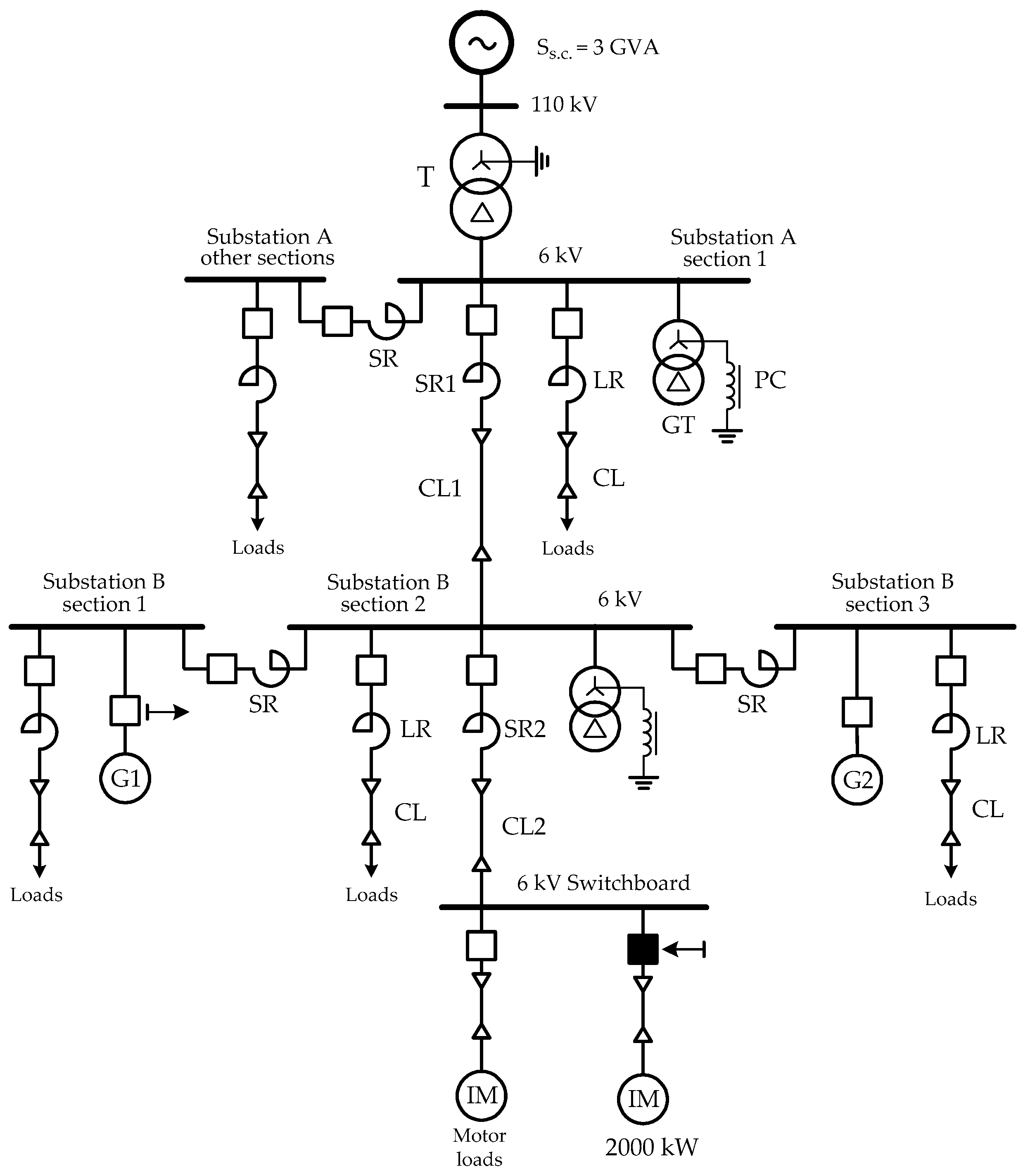
4.1. The Analysed Industrial Grid

The analysis of inrush currents when starting a powerful induction motor and their impact on operating an internal generator has been carried out on the example of a 6 kV industrial grid fragment shown in Figure 1. The power industrial grid contains two substations, A and B, which supply industrial loads and are connected by cable CL1 and reactor SR1. Main Substation B consists of three sections connected via SR reactors. The industrial grid is powered by an external 110/6 kV substation and 2.6 kV synchronous generators, G1 and G2, with a capacity of 25 MW each.
The industrial grid is a highly extensive cable industrial system with various possible operating configurations. Therefore, to compensate for capacitive currents, the industrial grid is equipped with two Petersen coils (PC), one for each main 6 kV switchgear. The units are connected to the busbars of Substations A and B by grounding transformers (GT). The fundamental power supply for all industrial loads such as the coking plant, rolling mill, compressor plant, etc., and MV auxiliaries of the industrial heat and power plant connected to Substation B is provided by internal synchronous generators and, in case of emergency conditions, Substation A as well.
The examined industrial grid is characterised by several topologies which are strictly dedicated to the emergency operation of the power system or applied during the technical inspection or routine maintenance of the electrical equipment and substation cell devices. Table 1 includes the main catalogue data of electrical equipment of the analysed industrial grid.
The synchronous generators are directly connected to the grid’s Substation B busbars and provide the appropriate active and reactive power as well as voltage stabilisation in the industrial grid. Each synchronous generator is equipped with a static-type exciter specifically dedicated to that type of synchronous machine. Table 2 presents the catalogue data of the synchronous generators installed and operating in the industrial heat and power plant.
The microprocessor control system ETW 30 [34] provides the ability of automatic and manual control modes of the generator exciter. The control system unit is responsible for stabilising the generator voltage and level of reactive power (if needed). The control system generates the output signal, which controls the transistor amplifier circuit and carries out all necessary functions for control, regulation, and protection of the generator excitation system [7,34]. The excitation systems were specially designed and have the settings calculated especially dedicated for synchronous generators which are operated in the examined industrial grid. Some of these values and criteria for manual and automatic control system modes are shown in Table 3.
The functional block of the ETW 30 control system with the static excitation system of the examined synchronous generator is presented below in Figure 2.
The automatic regulation system is equipped with the following software functions:
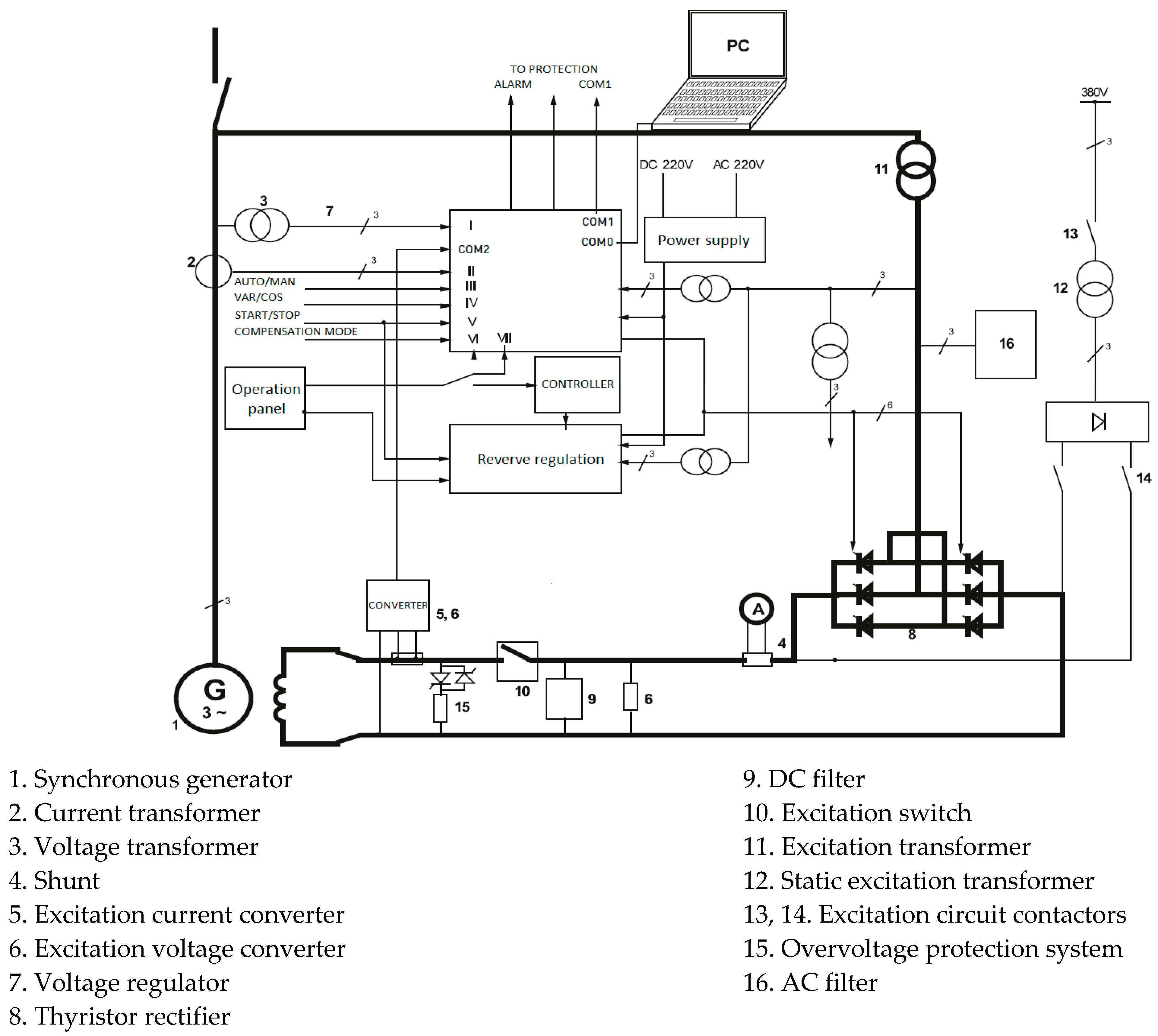
  • Voltage regulator, which ensures the generator voltage with an accuracy of ±0.5% of the rated voltage;
  • Excitation current limiter, which protects the unit against overload;
  • Excitation current limiter, which limits the generator’s reactive capacitive power to avoid overheat of stator iron packages and prevents trip off the generator due to failure of synchronization;
  • Induction current limiter, which reduces the generator voltage by lowering the frequency and protects the unit and power transformers from exceeding the permissible flux value in iron;
  • Tracking system, which ensures the proper excitation operation during changing modes between automatic and manual mode;
  • System stabilizer, which reduces the low-frequency oscillations of the rotor generator and allows its stabilization during operation at large loads.
Moreover, the voltage regulator provides two types of operation:
(a) Automatic (digital) control—with options to maintain the settings of generator voltage (the voltage control criterion), generator reactive power (the reactive power control criterion) or maintaining the power factor (the power factor criterion), and excitation current value (the excitation current criterion).
(b) Reserve (analogue) control—stabilizes the excitation current of the generator during malfunction of automatic digital (automatic) control and is used for checking and setting the generator protection.
The automatic control system is also equipped with a microprocessor unit with the protection mode, which constitutes a reserve concerning the basic, Digital Protection of the Synchronous Generator (DPSG) unit. The DPSG is a multifunctional digital relay that provides highly reliable protection for synchronous generators. Moreover, the microprocessor voltage regulator of the synchronous generator contains all necessary functions for control, regulation, and protection of the generator excitation system. It is equipped with RS-232 and RS-485 ports and the Modbus™ protocol for PC programming, measurement, and communication between the device and unit. The DPSG unit has been designed and programmed with specially calculated values and configured to prevent damage to the synchronous machine as well as failures and transient conditions that may affect the proper operation of the examined industrial grid equipment [37,38,39]. Table 4 shows some basic protection parameters of the synchronous generator digital protection.
In the industrial network under consideration, the studies are focused on starting the induction motor with a rated power of 2000 kW, which is powered by a 6 kV switchboard connected in series with the cable line CL2 and the current limiting reactor SR2 to Substation B. The 6 kV switchboard supplies the eleven MV induction motors with ratings from 320 kW to 2000 kW. As shown in studies [44], the current-limiting reactor SR2 has to be selected to limit the inrush current amplitudes under the frequent starts of MV induction motors and withstand significant repeated mechanical stresses. The catalogue data of the induction motor of 2000 kW, which drives the feed water pump of the industrial heat and power plant, are presented in Table 5.
As the induction motor starts the feed water pump, the motor inrush current amplitude increases approximately 5–6 times the nominal current amplitude depending on the industrial grid configuration. The transient current of the feeder is a sum of the starting motor current and currents of the MV motors connected to the switchboard and increased as a result of the busbar voltage sag. Ultimately though, despite the rotors’ slowdown of the motors, Ultimately though, despite the rotors’ slowdown of the motors, the impact of these currents on the feeder transient current during the starting motor of the feed water pump is insignificant. is insignificant. The technological procedure of the starting water pump begins with a closed stamping valve and an opened suction valve on of pipeline and the motor can be switched on only after checking the abovementioned conditions and venting the feed water pump. While the feed water pump reaches the running speed (after stabilization of rotational speed), the suction valve is opened, and the load of the feed water pump slowly increases to full load: the pump efficiency and its power increase. The procedure ends with a full opening of the stamping valve. In the case of the water pump shutting down, a technological procedure begins by closing the stamping valve and turning off the operated motor.
The 6 kV switchboard powering the feed water pump motor is implemented as 14 bays, which supply the auxiliaries of the CHP plant and are equipped with an ATS unit with digital protections on each feeder. The automatic switching on of the reserve power supply of the switchboard is realized between two sections of Substation B. The switchboard busbars feed 8 boiler induction motors, 4 with a power rating of 320 kW and the remaining 4 with a power of 500 kW, as well as 3 induction pump motors with power ratings of 630 kW, 900 kW, and 2000 kW.

4.2. Emergency Synchronous Generator Trip Analysis

An emergency event was registered within the analysed true industrial grid caused by starting a powerful induction motor when the grid’s synchronous generator was under manual control conditions. The deep analysis of the synchronous generator G1 tripping during the starting of the induction motor of the feed water pump has proved that the event was a result of the voltage sag caused by the motor starting current lasting about 5 s. During the motor starting, the voltage regulator of synchronous generator G1 was operated in manual mode (instead of automatic mode) due to the failure of the automatic voltage governor circuit. At the time of the synchronous generator G1 tripping, the industrial grid was operated with two synchronous generators, G1 and G2, each with active power equal to 25 MW and with an additional power supply from Substation A (see Figure 2). In normal conditions, the voltage governor of each synchronous generator is set to automatic mode. Thus, the voltage on the busbars of Switchboard B is kept between 6.20 to 6.36 kV, thus ensuring the reactive power demand of Substation B loads. The 6 kV switchboard load before the starting of the feed water pump induction motor was registered at about 3 MW and 1.70 MVAr. During the starting of the feed water pump induction motor, the voltage values on the operated synchronous generators and 6 kV switchboard were recorded by the protection system and are presented in Table 6.
During the starting of the feed water pump motor, the voltages on sections of the main Substation B were dropped and that caused an emergency tripping of the synchronous generator G1. Within the DPSG device of the synchronous generator G1, the protection relays had activated, which act as the trip of the machine by switching off the GCB (Generator Circuit Breaker), ECB (Exciter Circuit Breaker), and, in consequence, closing TV (Turbine Valve). After the time delay of ∆t > 2 s, the protections of overcurrent (OCP), undervoltage (UVP), and generator loss of excitation (ELP) were initiated. In addition, the signal relay of the unbalanced generator current (UCP) and stator fault protection (SFP) were active. In the cabinet of the DPSG device of synchronous generator G2, the signalisation from the undervoltage (UVP) was activated too. Still, it did not cause the tripping of the operated synchronous generator G2. To identify the reasons for the emergency tripping of the synchronous unit, the power plant staff carried out the necessary visual inspection and review of the G1 unit with measurement devices. The main event logs from digital protection devices and their time delays for synchronous generator G1 are presented in Table 7.
After inspection, the staff of the industrial heat and power plant decided to resynchronize generator G1 with the industrial grid in the manual control mode function of the voltage governor. At that time, the staff obtained information that the feeders and devices supplied by the other motors from the 6 kV switchboard were operated and none of them had switched off despite voltage sag. Nevertheless, the signal of undervoltage protection relay activation (UVP) had registered on the protection devices of the motor. The induction motor, which was being started, was switched off by undervoltage (UVP) and overcurrent protection (OCP).

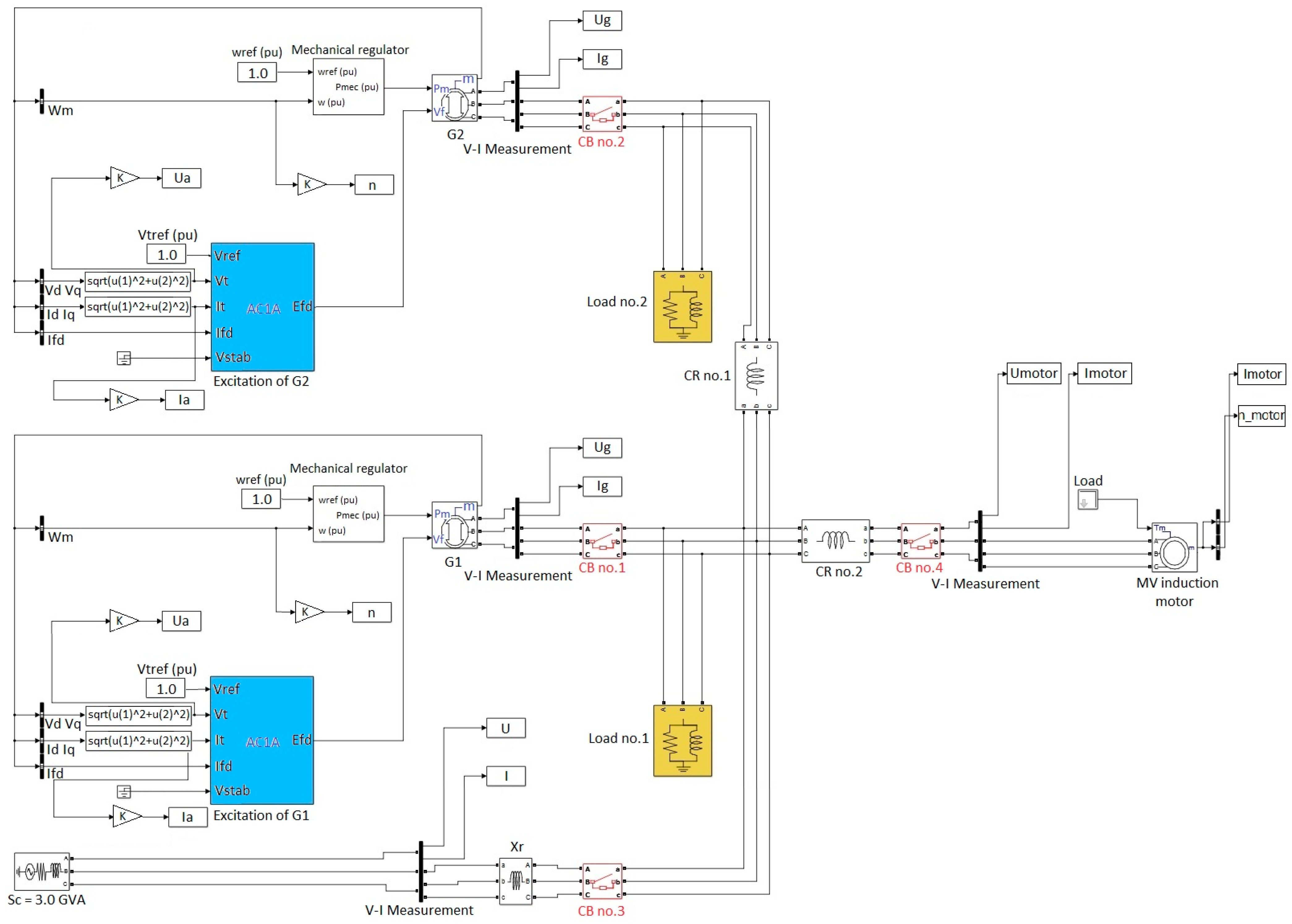
4.3. Modelling the Industrial Grid

Figure 3 presents a block diagram of the examined industrial grid model developed by the Sim Power System and Electric Drives libraries of the Matlab R2017b Simulink Software package. The following electrical equipment, devices, and motors from Figure 1 of the power grid single-line diagram were modelled with appropriate equivalent circuits and blocks and calculated by equipment catalogue data from Table 1, Table 2, and Table 5.
The synchronous generator equivalent was implemented as a three-phase machine block, modelled in the d-q rotor reference frame. The generator exciter and voltage control system are modelled by the AC1A Excitation System block. It models an AC unit with a diode rectifier to produce the field voltage U f required by the Synchronous Machine block. The implemented block is an adaptation of the AC1A excitation system of the IEEE 421 Standard Definitions for Excitation Systems for Synchronous Machines and exhibits good stability when starting the motor. The AC1A excitation system block was used instead of the AC4A and DC2A control systems because it provides better stability in less than 3 s and the field voltage U f reaches its limit without saturating in the distinction of the other models. Moreover, the results obtained with the AC4A and DC2A models are less efficient: the system takes more time to stabilize, and the stabilization of terminal voltage U t is obtained after 6 s.
The external power supply system is the equivalent of a bulk power system and Substation 110/6 kV operated with a direct grounded neutral point of the HV winding. The examined industrial grid operates with an ungrounded one. The grid reactors are modelled as equivalent R-L elements. The three-phase induction motor in the discussion was implemented by a three-phase induction machine model with a squirrel cage and was loaded by mechanical torque modelled by a Step block. The remaining three-phase induction motors were implemented as one block with appropriate equivalent parameters [45]. The 3-phase loads supplied from the 6 kV grid busses were implemented by 3-phase equivalent blocks from the Sim Power System library, which is characterised by active P and reactive Q powers and by nominal phase-to-phase voltage U n o m = 6000 V and nominal frequency f n o m = 50 Hz.
Transients caused by motors starting in the examined industrial power grid under study are characterized by significant variations in the time constants and natural frequencies of the equivalent circuit loops. Hence, automatic step recalculation using the ode23t solver was implemented to solve the model differential equations. The initial value of the step was taken as 0.5 ms. Applying that kind of solver provides the required accuracy and optimizes the time for solving model equations.

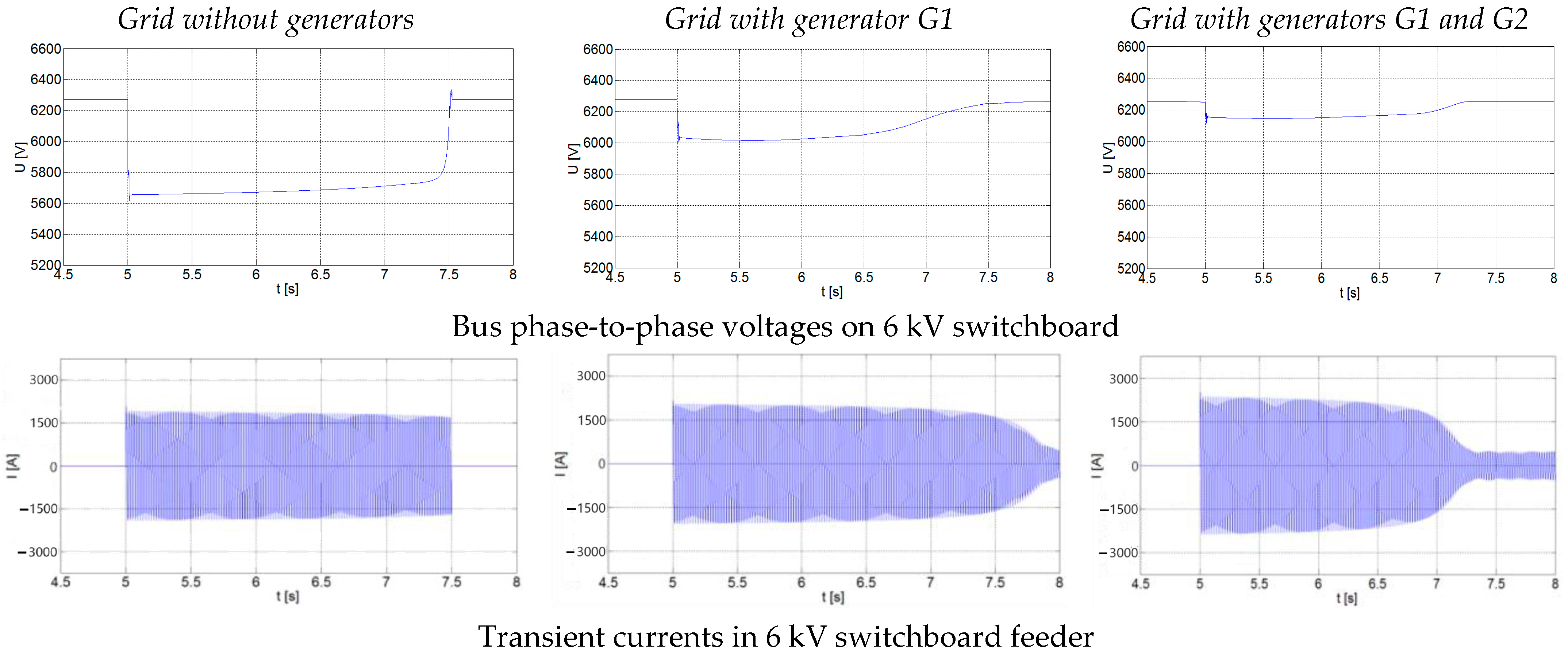
4.4. Results of Simulations and Discussion

The transient simulations during the starting water pump induction motor in the examined power industrial grid were modelled for two types of control modes of the synchronous generator G1 voltage regulator: automatic and manual. They were carried out under the same load conditions as the grid. All of the feeders are treated as feeders supplying the static loads and induction motors. Thus, starting the water pump induction motor affects the synchronous generators’ behaviours and the grid’s voltage stability.
At the first step of the research, the simulation transients when starting the grid induction motors were carried out. During the simulations, the impact of the resulting grid capacity on the voltage sags when starting induction motors of various ratings was analysed. The induction motor of each capacity was modelled on the base of the appropriate catalogue parameters and the load of the centrifugal pump.
The resulting grid capacity depends on the operating configuration of the industrial grid, which can include 3 possible options, where supplying the 6 kV switchboard is carried out by the following:
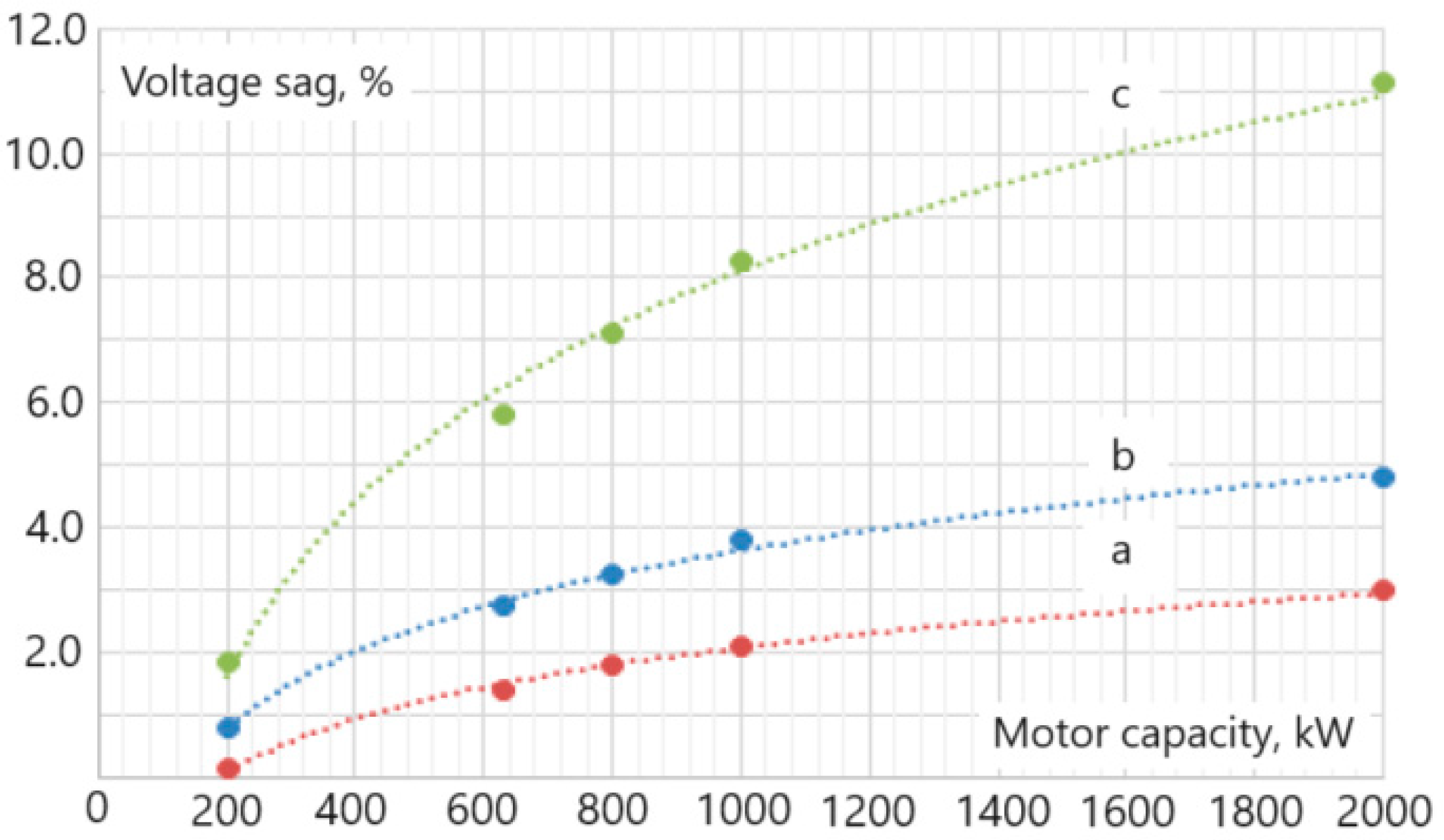
  • External bulk grid transformer 110/6 kV;
  • External bulk grid transformer 110/6 kV and generator G1;
  • External bulk grid transformer 110/6 kV and generators G1 and G2. Both generators G1 and G2 are operated with the automatic control of the excitation system.
Figure 4 shows an example of a simulation of starting the 2.0 MW feed water pump induction motor at the described grid configuration options. It has been proven through the simulations that power supplying auxiliaries of the industrial CHP only by the external bulk grid results in considerable voltage sag on the 6 kV switchgear bus of equal to 5.6 kV when starting the water pomp induction motor. That makes it impossible to start the induction motor for 2.5 s because of tripping the machine due to the undervoltage protection relay action. The presented situation also causes the risk of stoppage for the operating devices and other motors supplied from the 6 kV switchboard because of the decline in the bus voltage.
Operation of synchronous generators G1 and G2 within the industrial grid configuration which are controlled in automatic mode considerably improves the voltage profile on the 6 kV substation bus when starting the DOL motor. The residual voltage on the bus increases to 6.0 kV when starting the motor when generator G1 is operated within the grid configuration. In the case of generators G1 and G2, which are connected to the Substation B bus, the residual voltage increases to 6.1 kV. The starting time reduces and the motor requires approximately 2.3–2.6 s to achieve a rated speed condition.
Further, in the simulations, the analysis of transients has been carried out when starting other motors used within the industrial grid and having the following ratings: 2000 kW, 1000 kW, 800 kW, 630 kW, and 200 kW. The trials were conducted for the described previous grid configurations. The results of the simulations are summarised by dependencies in Figure 5. According to the requirements of Norms and Standards, for example, IEC 61000-2-12, PN EN 50160, UIE, and CENELEC [46], the meanings of per unit voltage sags in Figure 5 are calculated as the minimum RMS values of the sags during the disturbances and related to the rated voltage.
As the diagram presents, an increase in the induction motor rating results in the magnification of the voltage sag on the industrial grid buses. Moreover, the presence of synchronous generators operating in the industrial grid under study significantly reduces voltage sags on the grid busses when starting induction motors and alleviates an adverse impact on other devices and equipment of the industrial grid.
The next part of the research captures the study of the impact of the generator voltage control methods on the transients during the motor starting. In the first experiment, the motor starting was realised within the industrial grid configuration comprising the bulk power system supply and generators G1 and G2 with automatic control of the exciter voltage. In Figure 6a,b, one can see transient graphs of the experiment, where starting the induction motor in the fifth second causes voltage sags on the buses of synchronous generators G1 and G2, and their voltage controllers force the changes in field current to support voltages on the generator buses (Figure 6c). With automatic voltage control of the generators, the current from starting the induction motor does not cause significant voltage sags on the buses where the synchronous generators are connected. The voltages on the buses of generator G1 and generator G2 drop to 6.20 kV and 6.25 kV, respectively. In the shown example, the voltage regulator of generator G1 increases the field current during the sag to support the voltage on the generator bus. The voltage sags during the starting of the induction motor do not cause activation of DPSG protection relays of synchronous generators G1 and G2.
In the case of manual voltage control of synchronous generator G1, the motor starting causes the synchronous generator to trip after acting the DPSG relays. When transient, the generator G1 voltage drops to 5.02 kV and the generator G2 to 6.16 kV, as presented in Figure 6a,b. Exceeding the protection time settings of 2 s as well as the settings of overcurrent and undervoltage relays with values of 1.2 I n o m and 0.83 U n o m , respectively, causes the tripping of synchronous generator G1. The field current value set under manual voltage control of generator G1 for the pre-transient state does not allow supporting the generator G1 voltage at the required level during the motor starting. Thus, the motor starting cannot be carried due to the lower voltage in the 6 kV switchgear.
Comparing the simulation results with the event log data for the emergency tripping of the generator when starting the 2 MW induction motor in the industrial grid under study from Table 6 and Table 7, one can note satisfactory agreement with the registered values.

5. Conclusions

The presented article focuses on the problem of power compatibility of powerful induction motors in medium-voltage industrial grids with internal synchronous generators. The problem of starting induction motors is widely known and always of practical interest since the influence of the transients on the surrounding electrical equipment operation in the grid during the start of the motors depends on many factors that are related to the grid design and protection and control of the equipment. The analysis of the operational experience showed distinctive features of the transients when starting motors in real industrial grids containing internal synchronous generators, which can cause deep voltage sags, which negatively affect the operation of other equipment in the industrial grid. The excitation current variation rate of the industrial grid generator, as well as the depth and duration of the voltage sag on the bus during motor starting, depend not only on the technical data of the motor but also on the grid configuration and the type of generator control.
The operation of real industrial grids is accompanied by technological changes in their configuration and the operating conditions of individual generators, which causes different transient behaviours when the same motor is started. Incorrect selection and setting of the generator control and protection systems can cause the generator to be tripped. The real case of emergency tripping the industrial grid generator presented in the text of the article was carefully analysed and studied by the authors through the simulation and comparison with the registered log data of the event.
During the research, the authors developed a novel mathematical model based on Matlab/Simulink Software that ensures the possibility of studying features of transients in such industrial grids, considering the true characteristics of generator control and protection systems. In the framework of the model, a designer can analyse how the control modes of generators in such grids impact the nature of transients and the operation of generator protection systems when starting induction motors comparable with the industrial grid generator capacity. As shown by the comparison of simulation results with the logged grid operating values and generator protection activation events during one of the starts of a powerful motor in the true industrial grid, the developed model ensures high adequacy of the results in the field of the considered studies.
The main findings of the conducted research can be summarized as follows:
  • The availability of synchronous generators within the industrial grid supports better motor-starting conditions and lower voltage sags on the grid busses;
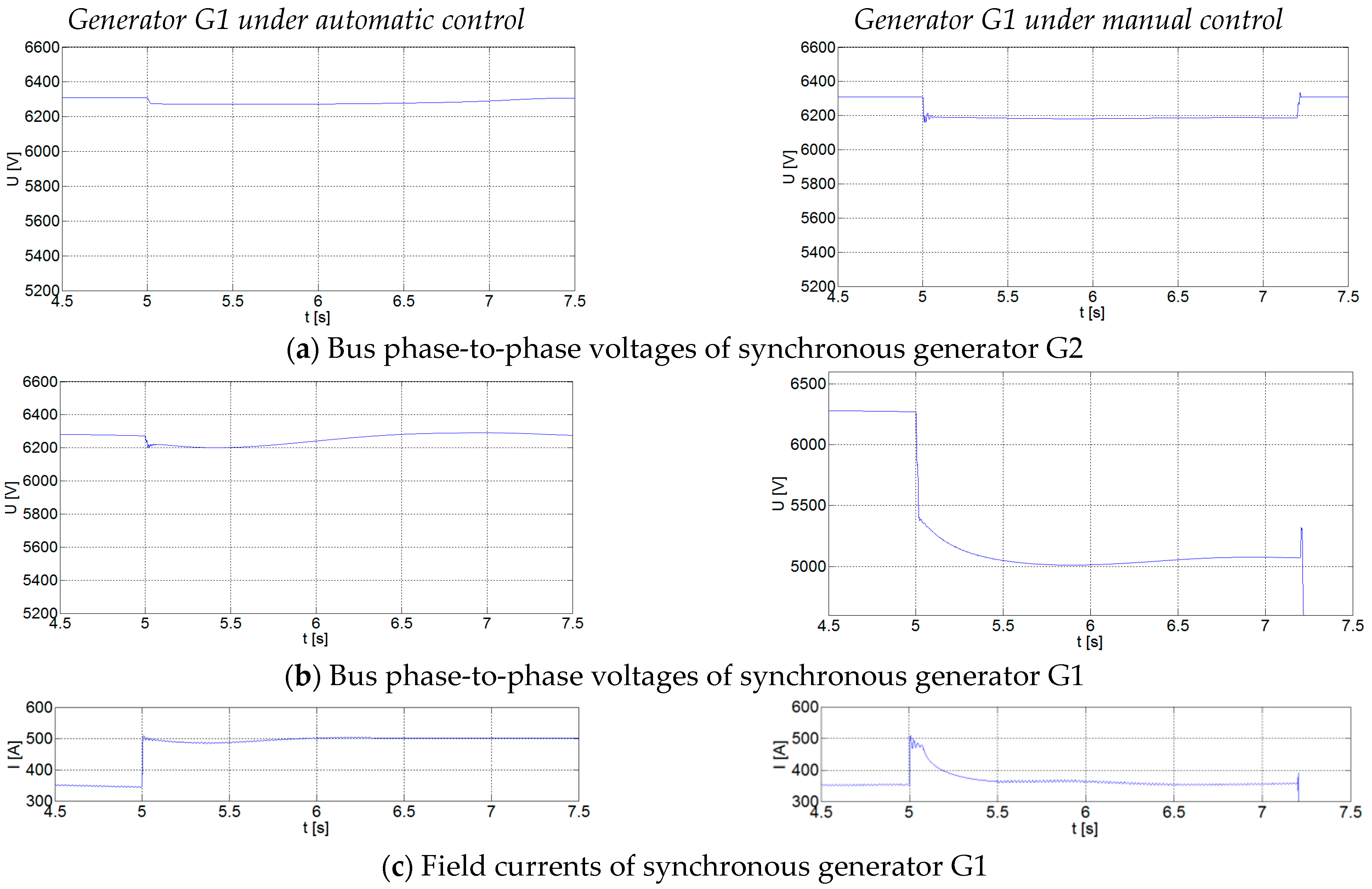
  • To start the large motors in an industrial grid containing synchronous generators, their control has to be set to automatic mode to prevent emergency tripping the grid equipment or generators;
  • The low excitation current in the manual control mode of the synchronous generator during the long-lasting starting of large motors may provoke significant disturbances in the grid operation when protections of grid units are not properly coordinated;
  • Settings of the generator protection system under-voltage and over-current relays have to be selected after a thorough analysis of the possible starting transients within the grid;
  • Voltage control of an internal synchronous generator in normal operating conditions of the industrial grid must be carried out in automatic control mode; manual voltage control mode shall be only used during the generator synchronizing to a bulk power grid or just for the generator testing or inspection;
  • Proper simulations of motor-starting transients in industrial grids containing internal generators can only be provided by adequate consideration of generator excitation control and protection systems, as well as the inertia characteristics of the grid motors and generators;
  • Careful analysis of transients when starting large induction motors allows for developing requirements for configurations and operating conditions of industrial electrical grids aiming to ensure a smooth and trouble-free operation of the facility, where such motors are usually used to drive critical processes and equipment.

Author Contributions

Conceptualization, Y.V. and M.G.; methodology, Y.V. and M.G.; investigation, Y.V. and M.G.; validation, Y.V. and M.G.; writing—original draft, Y.V. and M.G.; writing—review and editing, Y.V. and M.G.; supervision, Y.V.; project administration, Y.V.; funding acquisition, Y.V. All authors have read and agreed to the published version of the manuscript.

Funding

The present study was financially supported by AGH University of Krakow (grant AGH No. 16.16.210.476) and by the program “Excellence Initiative—Research University” for the AGH University of Krakow.

Data Availability Statement

Data are contained within the article.

Conflicts of Interest

The authors declare no conflicts of interest.

References

  1. Pawlik, M.; Strzelczyk, F. Power Plants; Scientific Publishing of PWN: Warsaw, Poland, 2012. [Google Scholar]
  2. Paska, J. Electricity Production; Scientific Publishing of the Warsaw University of Technology: Warsaw, Poland, 2020. [Google Scholar]
  3. Warecki, J.; Gajdzica, M. Energizing arc furnace transformer in power grid involving harmonic filter installation. Prz. Elektrotechniczny 2015, 4, 64–69. [Google Scholar] [CrossRef]
  4. Varetsky, Y.; Gajdzica, M. The procedure for selecting the ratings of capacitor banks and reactors of the filtering systems. Prz. Elektrotechniczny 2020, 3, 77–81. [Google Scholar] [CrossRef]
  5. Kotlicki, T. Improvement of energy efficiency in auxiliaries system of a power station. Energetyka 2013, 8, 627–630. [Google Scholar]
  6. Pawlik, M.; Skierski, J. Systems and Devices for Power Plant Auxiliaries; Scientific Publishing of WNT: Warsaw, Poland, 1986. [Google Scholar]
  7. Kotlicki, T. Energy efficiency of power plant auxiliaries. Prz. Elektrotechniczny 2021, 11, 154–158. [Google Scholar] [CrossRef]
  8. Latek, W. Turbogenerators; Scientific Publishing of WNT: Warsaw, Poland, 1973. [Google Scholar]
  9. Machowski, J.; Bialek, J.S.; Bumby, J.R. Power System Dynamics and Stability; John Wiley and Sons: Hoboken, NJ, USA, 1997. [Google Scholar]
  10. LeDoux, K.; Visser, P.W.; Hulin, J.D.; Nguyen, H. Starting large synchronous motors in weak power systems. In Proceedings of the Industry Applications Society 60th Annual Petroleum and Chemical Industry Conference, Chicago, IL, USA, 23–25 September 2013. [Google Scholar] [CrossRef]
  11. Yang, C.; Lee, B.S.; Jang, G.; Kim, S.; Jung, G.; Lee, J.; Shim, S.; Lim, Y.K.; Kim, J.; Park, S. Starting Current Analysis for Condition Monitoring of Medium Voltage Induction Motors in the Steel Industry. In Proceedings of the 2017 IEEE Industry Applications Society Annual Meeting, Cincinnati, OH, USA, 1–5 October 2017. [Google Scholar] [CrossRef]
  12. IEEE Std 3002.7-2018; IEEE Recommended Practice for Conducting Motor-Starting Studies and Analysis of Industrial and Commercial Power Systems. IEEE-SA Standards Board. IEEE: Piscataway, NJ, USA. [CrossRef]
  13. Hsu, C. Transient stability study of the large synchronous motors starting and operating for the isolated integrated steel-making facility. IEEE Trans. Ind. App. 2003, 39, 1436–1441. [Google Scholar] [CrossRef]
  14. Matanov, N. Study of the impact of induction motors starting on the supply voltage. In Proceedings of the 16th International Conference on Electrical Machines, Drives and Power Systems ELMA 2019, Varna, Bulgaria, 6–8 June 2019. [Google Scholar] [CrossRef]
  15. Matulewicz, W. Electrical Machines for Power Engineers; Scientific Publishing of the Gdańsk University of Technology: Warsaw, Poland, 1990. [Google Scholar]
  16. Paszek, W. Transient States of Alternating Current Electrical Machines; Scientific Publishing of WNT: Warsaw, Poland, 1986. [Google Scholar]
  17. Paszek, W. Dynamics of Alternating Current Electric Machines; Scientific Publishing of Helion: Gliwice, Poland, 1998. [Google Scholar]
  18. Sliwinski, T.; Głowacki, A. Starting Parameters of Induction Motors; Scientific Publishing of PWN: Warsaw, Poland, 1982. [Google Scholar]
  19. Fan, Z.; Shuqin, S.; Lei, Z.; Wenping, L.; Jian, W.; Liang, H. Study on Large Asynchronous Motor Starting Check for Auxiliary Power System. In Proceedings of the 2010 Asia-Pacific Power and Energy Engineering Conference, Chengdu, China, 28–31 March 2010. [Google Scholar] [CrossRef]
  20. Aree, P. Starting Time Calculation of Large Induction Motors Using their Manufacturer Technical Data. In Proceedings of the 2016 19th International Conference on Electrical Machines and Systems (ICEMS), Chiba, Japan, 13–16 November 2016. [Google Scholar]
  21. Gumilar, L.; Afandi, A.N.; Sujito; Faiz, M.R. Starting Induction Motor at Different Voltage Levels in the Electrical Power System. In Proceedings of the 2021 International Conference on Electrical and Information Technology (IEIT), Malang, Indonesia, 14–15 September 2021; pp. 269–273. [Google Scholar] [CrossRef]
  22. Xiangang, Y.; Qinchang, G.; Yingjie, T.; Aiqiang, P. Research on Calculation Model of Voltage Sags due to High Voltage and Great Power Motor Starting. In Proceedings of the China International Conference on Electricity Distribution, Nanjing, China, 1–7 September 2010. [Google Scholar]
  23. Dabbousi, R.; Refai, J.; Persson, H. Motor Starting Requirements and Their Effect on Motor Design. In Proceedings of the 4th European Conference on Electrical and Instrumentation Applications in the Petroleum & Chemical Industry, Paryż, France, 13–15 June 2007. [Google Scholar] [CrossRef]
  24. Rahamani, R.; Akbarzadeh Niaki, A.; Sadeghi, S.H.H. Large Induction Motor Starting Time Determination for the Purpose of Protection Coordination. In Proceedings of the 27th Iranian Conference on Electrical Engineering (ICEE2019), Yazd, Iran, 30 April–2 May 2019; pp. 475–480. [Google Scholar] [CrossRef]
  25. Silva, L.; Giancotti, K.; Amaro, F.; Pires, I. Analysis of Burn Out and Random Trips at Starting of a 2984 kW Induction Motor Driving a Main Blower. In Proceedings of the 2014 IEEE Industry Application Society Annual Meeting, Vancouver, BC, Canada, 5–9 October 2014; pp. 1–5. [Google Scholar] [CrossRef]
  26. Melfi, M.J.; Umans, S.D. Transients During Line-Starting of Squirrel-Cage Induction Motors. In Proceedings of the 2010 Record of Conference Papers Industry Applications Society 57th Annual Petroleum and Chemical Industry Conference (PCIC), San Antonio, TX, USA, 20–22 September 2010; pp. 1–8. [Google Scholar] [CrossRef]
  27. Liang, X.; Ilochonwu, O. Induction motor starting in practical industrial applications. IEEE Trans. Ind. App. 2011, 47, 271–280. [Google Scholar] [CrossRef]
  28. Wan-ting, H.; Ya-Jie, Y.; Si-ming, R.; Hai-yan, Z. A New Starting Method for Asynchronous Induction Motor. In Proceedings of the 2011 IEEE 2nd International Conference on Computing, Control and Industrial Engineering, Wuhan, China, 20–21 August 2011; pp. 341–344. [Google Scholar] [CrossRef]
  29. Blair, T.H. 3 Phase AC Motor Starting Methods: An Analysis of Reduced Voltage Starting Characteristics. In Proceedings of the IEEE SoutheastCon 2002 (Cat. No.02CH37283), Columbia, SC, USA, 5–7 April 2002; pp. 181–186. [Google Scholar] [CrossRef]
  30. VanderMeulen, A.H.; Natali, T.J.; Dionise, T.J.; Paradiso, G.; Ameele, K. Exploring new and conventional starting methods of large medium voltage induction motors on limited kVA sources. IEEE Trans. Ind. App. 2019, 55, 4474–4482. [Google Scholar] [CrossRef]
  31. Nevelsteen, J.; Aragon, H. Starting of Large Motors—Methods and Economics. IEEE Trans. Ind. App. 1989, 25, 1012–1018. [Google Scholar] [CrossRef]
  32. Simba, K.G.; Quilumba, F.L.; Granda, N.V. Parameter Estimation of a Three-Phase Induction Motor from Direct Starting Stator Transient Measurements. In Proceedings of the 2020 IEEE ANDESCON, Quito, Ecuador, 13–16 October 2020; pp. 1–5. [Google Scholar] [CrossRef]
  33. Li, X.; Xu, J.; Zhang, H. Research on Torque Ramp Current Limit Starting of Induction Motor Based on Dspic30f6014. In Proceedings of the 2017 IEEE 2nd Information Technology, Networking, Electronic and Automation Control Conference (ITNEC), Chengdu, China, 15–17 December 2017; pp. 1627–1630. [Google Scholar] [CrossRef]
  34. Cholewa, S.; Janson, Z. Modern excitation and voltage control systems for synchronous generators. Wiadomości Elektrotechniczne 2000, 4, 197–201. [Google Scholar]
  35. Hartmann, W. Advanced Generator Ground Fault Protections. In Proceedings of the 2015 68th Annual Conference for Protective Relay Engineers, College Station, TX, USA, 30 March–2 April 2015; pp. 345–360. [Google Scholar] [CrossRef]
  36. Gumilar, L.; Nugroho, W.S.; Sholeh, M. Power Quality of Synchronous Generator under Conditions of Starting Large Induction Motors Simultaneously and Sequentially. In Proceedings of the 7th International Conference on Electrical, Electronics and Information Engineering (ICEEIE), Malang, Indonesia, 2 October 2021; pp. 66–71. [Google Scholar] [CrossRef]
  37. IEEE Std C37.101-2006 (Revision of IEEE Std C37.101-1993); IEEE Guide for Generator Ground Protection. IEEE: Piscataway, NJ, USA, 2007. [CrossRef]
  38. IEEE Std C37.102-2006 (Revision of IEEE Std C37.102-1995); IEEE Guide for AC Generator Protection. IEEE: Piscataway, NJ, USA, 2007.
  39. IEEE Tutorial on the Protection of Synchronous Generators, 2nd ed.; Special Publication of the IEEE Power System Relaying Committee (PSRC); IEEE: Piscataway, NJ, USA, 2011.
  40. IEEE Std 142-2007 (Revision of IEEE Std 142-1991); IEEE Recommended Practice for Grounding of Industrial and Commercial Power Systems. IEEE: Piscataway, NJ, USA, 2007. [CrossRef]
  41. Bonnet, A.H.; Albers, T. Squirrel-cage rotor options for AC induction motors. IEEE Trans. Ind. App. 2001, 37, 1197–1209. [Google Scholar] [CrossRef]
  42. Bredthauer, J.; Struck, N. Starting of large medium voltage motors: Design, protection, and safety aspects. IEEE Trans. Ind. App. 1995, 31, 1167–1176. [Google Scholar] [CrossRef]
  43. Xia, Y.; Hu, Y.; Ai, M.; Liu, J. Temperature calculation of an induction motor in the starting process. IEEE Trans. App. Supercond. 2019, 29, 1–4. [Google Scholar] [CrossRef]
  44. Varetsky, Y.; Gajdzica, M. Study of short circuit and inrush current impact on the current-limiting reactor operation in an industrial grid. Energies 2023, 16, 811. [Google Scholar] [CrossRef]
  45. Sobczyk, T.J. Methodological Aspects of Mathematical Modelling of Induction Machines; Scientific Publishing of WNT: Warsaw, Poland, 2004. [Google Scholar]
  46. Hanzelka, Z. Voltage dips and short interruptions in power supply. Autom. Electrotech. Disturb. 2010, 1, 55–70. [Google Scholar]
Figure 1. Fragment of single-line diagram of the examined industrial grid.
Energies 17 01066 g001
Figure 2. The ETW 30 control system with excitation units for synchronous generators.
Energies 17 01066 g002
Figure 3. Block diagram of the industrial grid model.
Energies 17 01066 g003
Figure 4. Transients at starting 2.0 MW feed water pump induction motor under various grid configurations.
Energies 17 01066 g004
Figure 5. Voltage sags when starting induction motors of various ratings in the examined industrial grid configurations: (a) added generators G1 and G2 (red curve); (b) added generator G1 (blue curve); (c) without generators (green curve).
Energies 17 01066 g005
Figure 6. The transients in the grid generators under automatic and manual controls of generator G1.
Energies 17 01066 g006
Table 1. Catalogue data of the industrial grid equipment.
Grid ComponentParameterUnitValue
Supply systemTransformer rated voltage, U n kV/kV110/6
Transformer capacity, S n MVA31.50
Short circuit power, S s c GVA3.00
Cable lines CL1 and CL2Rated voltage, U n kV6.00
Specific resistance, R 0 Ω/km0.16
Specific inductance, L 0 mH/km0.34
Specific capacitance, C 0 µF/km0.44
Section reactor SRRated current, I n kA0.60
Resistance, R Ω0.35
Inductance, L mH0.45
Rated SC current peak, I p kA32.00
Section reactors SR1 and SR2Rated current, I n kA1.60
Resistance, R Ω0.13
Inductance, L mH0.22
Rated SC current peak, I p kA52.00
Table 2. Catalogue data of the synchronous generator.
Component RatingsParameterUnitValue
Synchronous generators G1, G2Rated active power, P g n MW25.00
Rated voltage, U g n kV6.30
Rated current, I g n kA2.25
Rated speed, n g n r.p.m.3000.00
Power factor, cosφ-0.80
Stator resistance, R s 5.22
Subtransient reactance, X d %14.30
Transient reactance, X d %24.00
Synchronous reactance, X d %245.00
Winding time constant, T d s1.20
Mechanical time constant, T m s9.32
Inertia moment, J T·m21.35
Excitation unitRated power, P a n kW150.00
Rated voltage, U a n V250.00
Rated current, I a n A600.00
Table 3. Excitation system settings.
ParameterAccuracy and Range of RegulationUnitValue
Voltage limiter±0.5 U g n
U g = ( 0.85 1.1 ) U g n
U a   m a x = 1.6 U a n
%
kV
V
-
5.35–6.93
400
Current limiter±1.0 I a
I a   = ( 0.5 1.1 ) I a n
I a   m a x = 1.1 I a n
%
A
A
-
420–660
660
Table 4. Protection settings of DPSG relays for synchronous generators.
Protection TypeUnitSetting Value
Overcurrent protectionIr [kA]
tmax [s]
1.20In
2.00
Differential protection Ir [kA]
tmax [s]
0.20I
0.02
Overvoltage protection Ur [kV]
tmax [s]
1.23U
2.00
Undervoltage protection Ur [kV]
tmax [s]
0.83U
2.00
Frequency protectionUr [kV]
fr [Hz]
tmax [s]
0.40U
0.95f
10.00
Impedance Ir [kA]
Zr [Ω]
tmax [s]
0.10In
6.00
3.00
Stator ground fault protection Ir [kA]1.20In
Unbalance protectionIr [kA]
tmin [s]
tmax [s]
0.05In
10.00
300.00
Reverse powerPr [kW]0.01Pn
Table 5. Catalogue data of the feed water pump induction motor.
ParameterUnitValue
Rated power, P n MW2.0
Rated voltage, U n kV6.0
Rated current, I n A240.0
Starting coefficient, K I -6.5
Rated speed, n n r.p.m.2975.0
Efficiency, η %95.0
Inertia moment, J kg·m238.5
Power factor, cos φ -0.85
Table 6. The values of voltages during the starting of the feed water pump induction motor.
The Measurement PointU [kV]
Before StartingDuring Starting
Synchronous generator G16.285.02
Synchronous generator G26.256.15
6 kV switchboard6.224.96
Table 7. The event logs from DPSG of synchronous generator G1.
Time Delay of Relay ProtectionProtection Relay TypeProtection Relay Event
∆t [s]: 00:00–01:00OCPactivation
ELPactivation
UCPactivation
∆t [s]: 01:00–02:00OCPactivation
ELPactivation
UCPactivation
UVPactivation
SFPactivation
∆t [s]: > 02:00OCPaction
UVPaction
ELPaction
UCPactivation
SFPactivation
GCBswitching off the GCB
ECBswitching off the ECB
TVclosing the TV
Disclaimer/Publisher’s Note: The statements, opinions and data contained in all publications are solely those of the individual author(s) and contributor(s) and not of MDPI and/or the editor(s). MDPI and/or the editor(s) disclaim responsibility for any injury to people or property resulting from any ideas, methods, instructions or products referred to in the content.

