Article

Development of Dual Intake Port Technology in ORC-Based Power Unit Driven by Solar-Assisted Reservoir

Department of Industrial and Information Engineering and Economics, University of L’Aquila, Piazzale Ernesto Pontieri, Monteluco di Roio, 67100 L’Aquila, Italy
*
Author to whom correspondence should be addressed.
Energies 2024, 17(5), 1021; https://doi.org/10.3390/en17051021
Submission received: 3 January 2024 / Revised: 31 January 2024 / Accepted: 1 February 2024 / Published: 22 February 2024

Abstract

:
The ORC-based micro-cogeneration systems exploiting a solar source to generate electricity and domestic hot water (DHW) simultaneously are a promising solution to reduce CO2 emissions in the residential sector. In recent years, a huge amount of attention was focused on the development of a technological solution allowing improved performance of solar ORC-based systems frequently working under off-design conditions due to the intermittence of the solar source availability and to the variability in domestic hot water demand. The optimization efforts are focused on the improvement of component technology and plant architecture. The expander is retained as the key component of such micro-cogeneration units. Generally, volumetric machines are adopted thanks to their better capability to deal with severe off-design conditions. Among the volumetric expanders, scroll machines are one of the best candidates thanks to their reliability and to their flexibility in managing two-phase working fluid. Their good efficiency adds further interest to place them among the best candidate machines to be considered. Nevertheless, similarly to other volumetric expanders, an additional research effort is needed toward efficiency improvement. The fixed built-in volume ratio, in fact, could produce an unsteady under- or over-expansion during vane filling and emptying, mainly when the operating conditions depart from the designed ones. To overcome this phenomenon, a dual intake port (DIP) technology was also introduced for the scroll expander. Such technology allows widening the angular extension of the intake phase, thus adapting the ratio between the intake and exhaust volume (so called built-in volume ratio) to the operating condition. Moreover, DIP technology allows increasing the permeability of the machine, ensuring a resulting higher mass flow rate for a given pressure difference at the expander side. On the other hand, for a given mass flow rate, the expander intake pressure diminishes with a positive benefit on scroll efficiency. DIP benefits were already proven experimentally and theoretically in previous works by the authors for Sliding Rotary Vane Expanders (SVRE). In the present paper, the impact of the DIP technology was assessed in a solar-assisted ORC-based micro-cogeneration system operating with scroll expanders and being characterized by reduced power (hundreds of W). It was found that the DIP Scroll allows elaboration of a 32% higher mass flow rate for a given pressure difference between intake and expander sides for the application at hand. This leads to an average power increase of 10% and to an improvement of up to 5% of the expander mechanical efficiency. Such results are particularly interesting for micro-cogeneration ORC-based units that are solar-assisted. Indeed, the high variability of hot source and DHW demand makes the operation of the DIP expander at a wide range of operating conditions. The experimental activity conducted confirms the suitability of the DIP expander to exploit as much as possible the thermal power available from a hot source even when at variable temperatures during operation.

1. Introduction

One of the most important technological solutions to exploit low-temperature hot sources is the power unit based on Organic Rankine Cycle (ORC) [1]. These, indeed, allow production of mechanical power recovered from the thermal power of waste heat in internal combustion engines [2,3,4] and the industrial sector [5,6]. Moreover, ORC-based power units can recover low- and medium-grade thermal energy of renewable hot sources like solar [7,8,9], geothermal [10,11] and biomasses after combustion [12]. To maximize the performance of the unit, the proper design and selection of the plant components is fundamental. The key component is certainly the expander, which in small- and medium-scale applications is usually a volumetric machine. Indeed, volumetric expanders are chosen for their low rotational speed often favoring a direct connection with the conventional electrical machines, the capability to elaborate two-phase working fluids and small mass flow rates with respect to the design value and pressure ratios different from the rated value [13]. The selection of the expander depends on many factors and on the application under consideration, hence, it is not possible to define an optimal technological solution for every situation [14]. The scroll expander presents high efficiency, simple manufacture and light weight but it shows low capacity and a more complex geometry with respect to the other volumetric machines [14]. Another advantage is the rolling motion of the contact point which provides less resistance than the sliding friction which is typical of sliding rotary vanes. Moreover, the rolling contact acts as a seal, thus reducing the oil amount for sealing purposes. Hence, both mechanical and volumetric losses are the subject of further studies aimed at real reductions being these losses the main limit to increase the overall efficiency [15]. The resulting efficiency improvements produce an increase in the overall efficiency of the unit, particularly expected considering the intrinsic low efficiency due to the low-grade hot source thermal energy.
The screw expander ensures achieving a high efficiency in off-design conditions and tolerates low speed and two-phases fluid. On the other hand, the manufacture of the machine has some complexity. The sealing behavior, as well, represents a critical aspect which still deserves attention. A deep analysis of screw machines was provided in [16,17,18]. In [17], an advanced design environment was developed for screw machines allowing a reduced design time, thus achieving a high quality of final design. Moreover, the model requires few inputs and allows communication with commercial 3D software packages, thus providing a parametric model and manufacturing drawing of the screw machine [17]. Piston expanders are suitable for those applications characterized by a huge expansion ratio thanks to their large built-in volume ratio [19]. Nevertheless, cons are the presence of intake and exhaust valves and the torque pulsation [13]. A novel radial piston prototype was developed and widely experimentally characterized in [20]. Sliding Rotary Vane Expanders (SVRE) are capable with dealing with high pressure [20] and present a high expansion ratio [21]. Moreover, they are characterized by simple manufacture and lower cost [22]. Nevertheless, volumetric losses are recognized as the main source of efficiency penalization for this device [23,24].
The Dual Intake Port (DIP) is one of the most interesting technologies allowing introduction of significant benefits [24,25]. It consists of introducing an auxiliary secondary inlet port after the closure of the main one, able to refill a vane which has an increased volume with respect to that it had when the first port was closed. In this way, additional fluid is entered inside the machine, the vane pressure is increased as well up to the inlet expander pressure. The authors experimentally and theoretically proved in their previous works the significant performance benefit when DIP technology was introduced in the Sliding Rotary Vane Expander. In fact, as expected, a mechanical power increase was observed due to a higher fluid flow rate elaborated for a given pressure difference between expander intake and exhaust side [24]. The authors introduced theoretically and experimentally the concept of permeability which synthetizes the two effects. In fact, permeability represents the attitude of the machine to be crossed by working fluid. The higher the permeability, the greater the mass flow rate elaborated by the machine for a given pressure difference between intake and exhaust sides. DIP enhances permeability as it consists, as already observed, in the introduction of a further intake port placed after the main intake one in correspondence of the expansion phase when the chamber is enlarging. In this way, the additional mass flow rate entering the expander chamber boosts the pressure, thus producing more power. DIP technology also provides an efficiency improvement with a proper design and angular position of auxiliary ports [24]. As demonstrated in authors previous works [24], DIP technology can be used in SVRE design, allowing a downsizing of the expander with benefits in terms of machine weight and efficiency. In [25], the authors provided a feasibility analysis of DIP technology when it was applied to a scroll expander.
Up to date, DIP adoption was not considered for a scroll expander operating in micro-cogeneration ORC-based units. The reduced dimensions of the expander, in fact, makes difficult the construction of a second port, which would require space inside the vane, and the respecting of some design rules. The micro-cogeneration units require, as well, the capability to deal with a high variability of hot source which reflects on the superheating degree of the fluid which, under particular severe situations, can remain at a wet saturated state. The hot source, in fact, is represented by the hot water heated by solar power usually stored in a Thermal Energy Storage (TES) tank. The same hot water is employed to produce domestic hot water (DHW) whose demand is highly variable and not predictable. It must be observed that also small performance increases are particularly suitable in the specific application which is characterized by small overall conversion efficiency from thermal to mechanical and definitively electrical energy. Any improvement due to the DIP technology in the expander’s performance is particularly interesting considering the intrinsic low efficiency of the units fed by solar energy. The low-grade thermal energy of the hot source, in fact, and the proximity to the cold source represented by the environmental conditions limit the theoretical efficiency of a Carnot’s cycle to a few percentage points. So, any improvement is significantly suitable.
In order to assess the effectiveness of DIP technology in scroll expanders of very reduced size (power level of few hundreds of kW), a fully instrumented ORC-based unit developed to be integrated to 15 m2 of solar flat plate thermal collectors was experimentally characterized. For experimental convenience, the solar power was simulated by two electrical resistances (12 kW each) whose modulation reproduced closely the effects of the solar irradiation on the flat panels. Experimental data were used to validate the model of the scroll expander having only a single intake port, as that is conventional. Once validated, the scroll expander was modified, manufacturing inside it a second intake port, and a comparative analysis with the OEM version (Single Port Technology, SIP) was provided over a wide range of operating conditions. A wider software platform built in GT-Suite™ 2022 of the overall micro-ORC-based unit was developed which is the base of a future model-based control strategy.

2. Materials and Methods

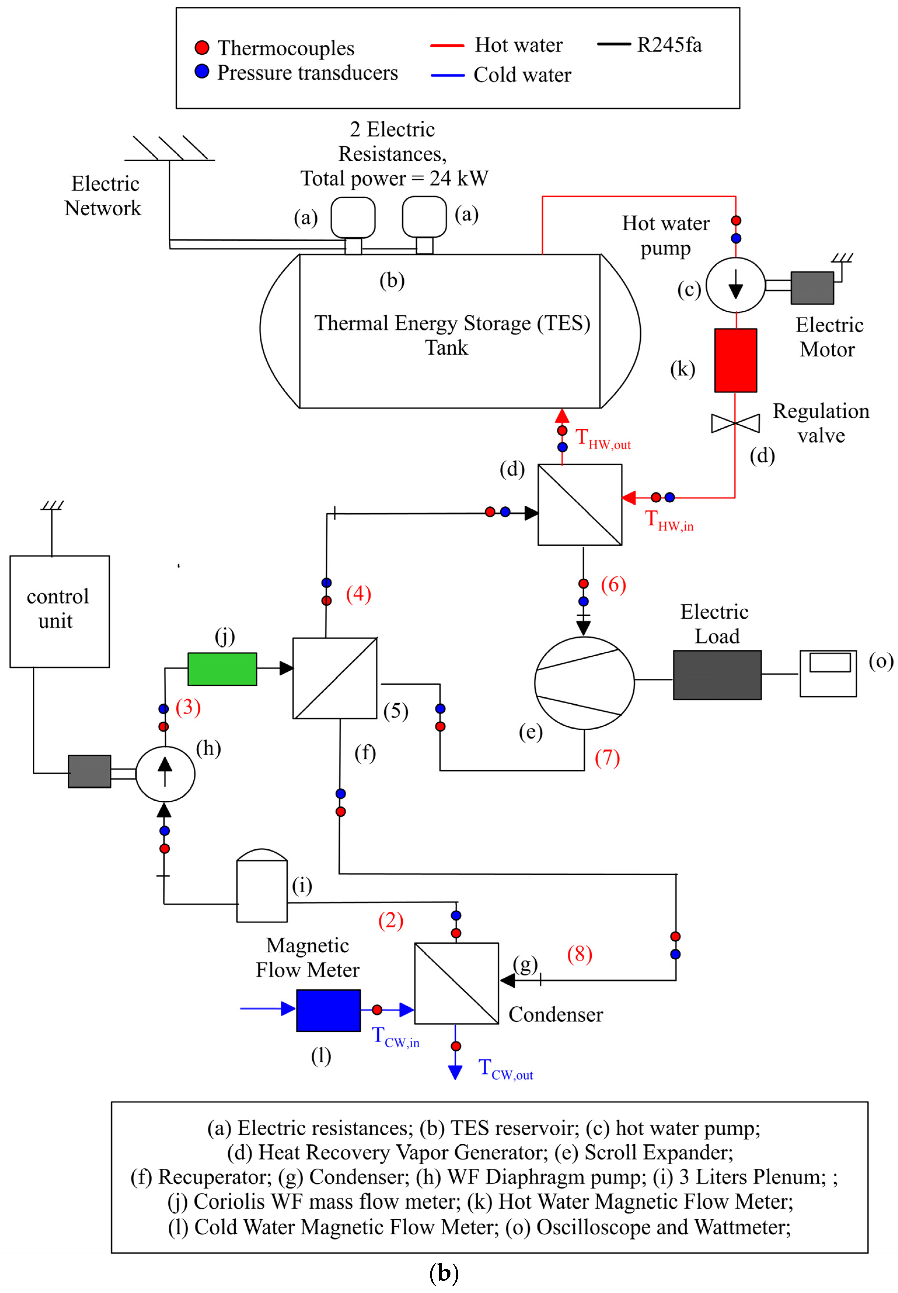
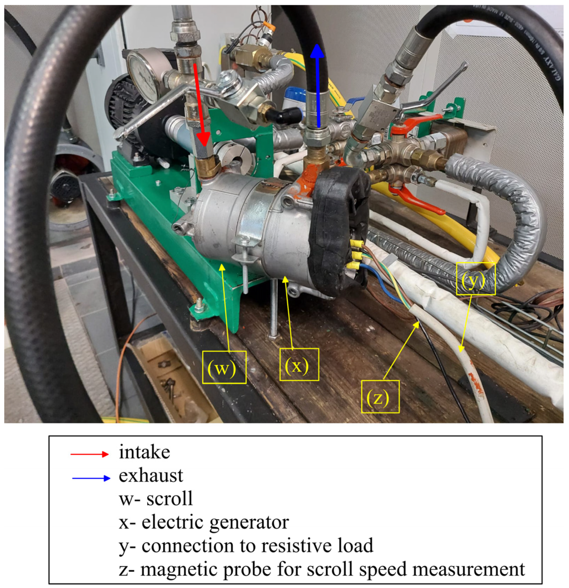
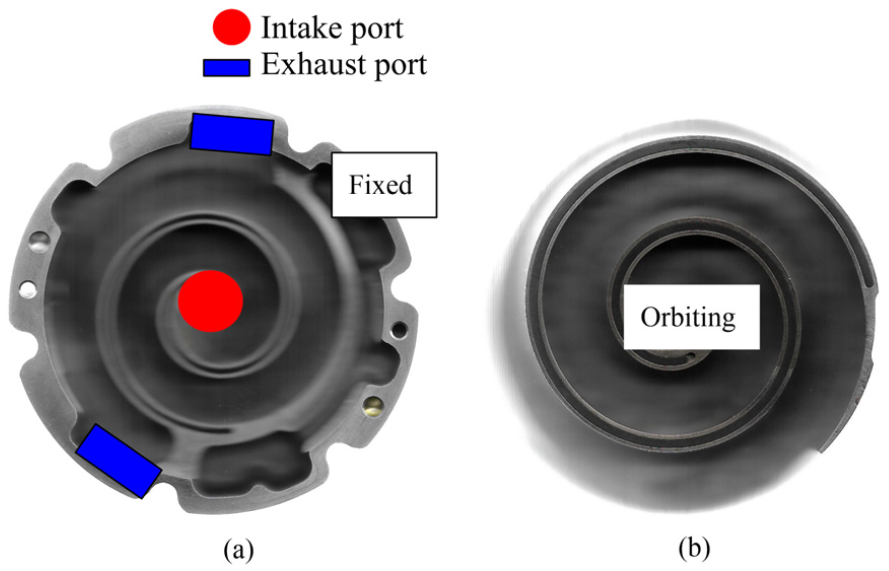
2.1. Experimental Test Bench

A wide experimental characterization was carried out on a scroll expander introduced on a fully instrumented ORC-based power unit (Figure 1) where the working fluid is R245 fa. The working fluid is mixed with a POE oil whose amount is equal to 5% of the working fluid charge. The lubrication oil mixed inside the working fluid allows to lubricate the moving parts of the expander and pump, also performing a sealing effect.
The ORC-based unit was developed for micro-cogeneration purposes. Indeed, it was conceived to be integrated to flat solar thermal collector for the simultaneous production of heat and electric power. In the experimental facility, the integration of the ORC-based power unit with the flat plate solar thermal collector was reproduced thanks to two electric resistances (12 kW each). The resistances heat up 150 L of hot water stored in the TES, which behaves as the hot source of the recovery unit modulated by a dedicated hot water pump (c). The same hot water allows to fulfil the thermal demand requested by domestic uses (domestic hot water, DHW) which usually is the main goal of flat plate solar collectors.
The hot water was sent to a Heat Recovery Vapor Generator (d) where the thermal power was provided to the working fluid which enters the HRVG as subcooled liquid (4) and exits the heat exchanger as slight superheated vapor (5). Then, working fluid enters the scroll expander (e) (Figure 2) which produces electric power dissipated on a resistive load in the test bench.
A further heat exchanger (RHX) is placed at the expander outlet to perform a recuperative stage. Indeed, the hot working fluid exiting the expander enters the RHX (f) prior to entering the condenser (g). In this way, the working fluid pumped by a diaphragm pump (h) enters the cold side of RHX and it is pre-heated before entering the HRVG. A small reservoir with a capacity of 3 L (i) was placed upstream of the pump of the working fluid and downstream of the condenser (g) to dampen eventual pressure pulsation and sustain a sudden request of working fluid. Upstream and downstream, component, pressure and temperature transducers were placed to fully characterize the plant from a thermodynamic point of view. The working fluid mass flow rate was measured thanks to a Coriolis mass flow meter (j), whereas the hot water at HRVG and cold water at condenser were assessed though magnetic flow meter (k and l, respectively). The power produced by the expander and of that absorbed by the pump were also measured by Wattmeter (o). The scroll speed was measured through a magnetic probe introduced inside the chamber (o). The measurement uncertainties are reported in Table 1.
Figure 1. (a) Solar-driven ORC-based power unit. (b) Solar-driven ORC-based power unit.
Energies 17 01021 g001aEnergies 17 01021 g001b
The system was designed to be integrated with 15 m2 flat solar collector mounted on a rooftop in the center of Italy. A Thermal Energy Storage (TES) tank of 150 L was integrated into the system to face the daily fluctuation of solar source and domestic hot water (DHW) demand. In this study, the situation in which the ORC-based power unit is driven exclusively by the TES tank is considered. In this way, the extra thermal power stored is exploited to produce electric power once the heat demand is fulfilled.
The electricity production cools the water inside the TES, so allowing a continuous solar energy recuperation which would be interrupted when the maximum temperature of the hot water inside the tank is reached. Based on the analysis performed in previous studies, in a day the unit can be operated driven by TES tank thermal discharge aimed at the electricity production. Considering the heat demand to fulfill (main objective of the co-generative unit) and the dynamics of the unit and of the TES, up to seven activations of the ORC-based power unit can be performed in a day. Six activations last 15 min and produce a useful partial thermal energy discharge of TES whose temperature decreases in the range 110–90 °C. When a temperature of 90 °C is reached, the solar energy recuperation can be re-switched on, allowing an additional recovery which could not have occurred if the tank had not been cooled by the ORC-based unit during electricity production, At the end of the day once the DWH demand is satisfied, a last activation of the unit can be performed exploiting a complete thermal discharge of TES. A residual thermal energy is kept inside the tank to fulfill the thermal demand of the day after before solar energy would be available. To experimentally analyze this operating strategy, the integration of the ORC unit with flat solar collector is reproduced through the adoption of the two electric resistances (12 kW each). This ensures to shorten the recharge time of the TES tank, thus increasing the number of tests that can be performed in a day. Existing flat plate solar collectors could be retrofitted with the recovery unit, which definitively behaves as micro-cogeneration system.
Figure 2. Scroll Expander configuration.
Energies 17 01021 g002

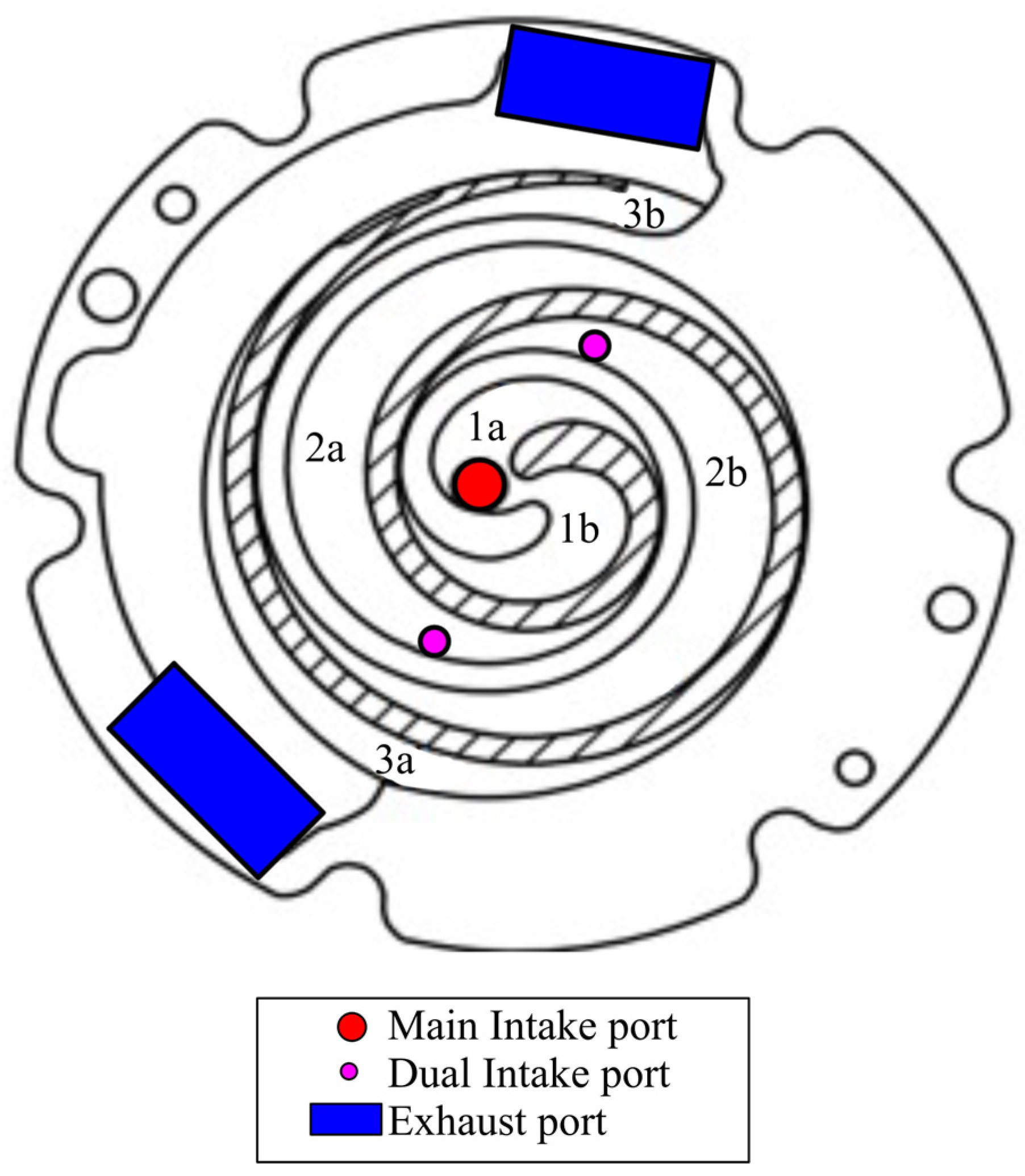
2.2. Theoretical Model

The fixed and orbiting scrolls of the adopted expander are shown in Figure 3a and Figure 3b, respectively. The two scrolls define six chambers as reported in Figure 4. According to the figure, chambers 1a and 1b are performing the intake phase whose duration lasts from 0 up to 360°. Hence, after a complete rotation, the intake phase is completed and chambers 2a and 2b expand. The expansion proceeds for a rotation of 277° after the end of the intake phase. Hence, considering the start of the cycle (0°) corresponding to the start of the intake phase, the expansion phase ends at 637°, given by the sum of 360° (duration of the intake phase) and 277° (duration of the expansion). Discharge phase starts immediately after the end of expansion (637°), and, after a complete rotation (360°) it is completed. Therefore, adding the angular extension of the different phases (intake, expansion and discharge), the angle duration of a cycle can be evaluated (360° + 277° + 360° = 997°). Therefore, such behavior suggests a symmetric structure for the model as can be seen in Figure 5. Such a model was developed in [25] and refined here to adapt it to the considered machine.
Elements (a) and (e) are plenum of infinite capacity representing the intake and exhaust environments, respectively. Here, boundary conditions can be introduced: working fluid mass flow rate and temperature of working fluid at expander intake in (a) and expander exhaust temperature in (e). Elements (b) and (d) represent the intake and the exhaust pipes, respectively. They are discretized into multiple sub-elements; for each of them the mass, momentum and energy conservation equations are solved through an explicit integration method [25]. Hence, a mono-dimensional (1D) thermo-fluid-dynamic analysis was applied to reproduce the intake and exhaust phases.
The transformations inside the chambers were instead evaluated through a zero-dimensional approach. Element (c) represents the i-chamber defined by orbiting and rotating scroll. It is important to notice that chambers 1a and 1b, 2a and 2b, and 3a and 3b present a symmetrical variation during rotation (Figure 5, Figure 6 and Figure 7). Therefore, the model can be subdivided in two parts: one referred to the chambers 1a, 2a and 3a, and the other referred to chambers 1b, 2b and 3b (Figure 5). Hence, each chamber is treated as a lumped volume capacity whose angular variation is ruled by elements (m). It is worth noticing that chambers 2a and 3a present a phase displacement of 360° and 720° with respect to chamber 1a. The same phase displacement applies for chambers 2b and 3b with respect to 1b. In other words, due its symmetrical operation, the scroll volume variations are reproduced by two equivalent shafts which drive chambers 1a, 2a, 3a (h); and 1b, 2b, 3b (i).
Hence, it is possible to reproduce in an equivalent mode the variation in the chambers caused by the relative motion between the rotating and fixed spirals. The revolution speed at which the expander rotates is set trough elements (j and k).
Adopting this approach, the same volume variation in the real case can be reproduced. Indeed, from a 0D point of view, it is important the volume variation in each chamber focuses on the fluid volume variation. This makes it possible to use the equivalent procedure adopted. Shaft (h) and (i) are connected respectively to elements j and k which provide the boundary conditions of speed rotation.
The considered scroll being a hermetic machine, the electric generator is internally connected to the same shaft and the produced power is dissipated on a resistive electric load. Due to this arrangement, the revolution speed of the integrated scroll is not externally controlled but it depends on the dynamic equilibrium between the generator and the expander. As the experimental analysis shows a linear dependence of revolution speed as function of mass flow rate, such linear relation was considered as a boundary condition. The mass flow rates expanding inside the machine or the electric load are the main variables responsible for different speeds of rotation.
Concerning the modeling of the losses (volumetric and mechanical), it follows again a 0D approach. The volumetric losses refer to the leakage paths reported in Figure 4. In Figure 4, radial (a) and flank (b) leakages are reported, which are the main source of volumetric losses. The radial leakages (a) take place in the gap between the orbiting spirals and the base of the fixed scroll and vice versa, whereas the flank ones (b) are across the clearance between the spirals. They have been represented by flow rates which move following a negative pressure gradient across a cross section given by the gaps. Flank leakages are modelled through elements (f) in Figure 5, whereas radial ones are taken into account by elements (g).
Figure 3. Fixed (a) and orbiting (b) scroll expanders.
Energies 17 01021 g003
Figure 4. Modeling of scroll expander.
Energies 17 01021 g004
The evaluation of the chamber volume variation and of the volumetric losses allows to represent the pressure value inside each chamber as function of angular rotation. Thus, it is possible to evaluate the indicated power as reported in Equation (1). Indicated power represents the work provided by the working fluid to the machine mobile components. For the symmetric configurations adopted, on each shaft is gathered half of the total indicated power. Hence, the sum of the indicated power on the two shaft represents the total power exchanged by the working fluid and the mobile components Pind.
P i n d = i = 1 N v p i d V i t c y c l e
Once the indicated power is evaluated, to assess the mechanical power produced by the expander, from Pind the mechanical losses should be subtracted as in Equation (2).
P m e c h = P i n d P l o s s e s
The mechanical losses have been modelled making reference to a mechanical efficiency map, following the approach in [25]. Once the model of the expander was validated according to its real geometry which considered a conventional SIP solution, a second intake port was introduced in the model (DIP) and the performances predicted. The introduction of DIP port involved only slight modifications considering that the scroll structure leads to pairs of chambers (1a and 1b, 2a and 2b, 3a and 3b) whose volume symmetrically varies during rotation. Hence, the two intake ports must be symmetrically placed to overcome the unavoidable disequilibrium which would have been produced according to a different positioning [25].
Figure 5. Scroll theoretical model.
Energies 17 01021 g005
Figure 6. DIP Scroll expander.
Energies 17 01021 g006
This meant that the second ports were placed on the fixed scroll where the main intake port is also located (Figure 6). So, no adduction pipes are required, with the intake phase being axial and performed through the same intake manifold (Figure 3 and Figure 6).
As claimed above, for the considered scroll expander, a rotation of 997° is needed to complete the whole cycle. For the adopted angular convention, the intake phase is performed between 0° and 360°; once the intake phase is performed, the expansion phase takes place up to 637° and, finally, the discharge phase happens, ending at 997°. The DIP ports represented in Figure 6 were installed to feed the machine during the expansion phase. So, the DIP starts at 360° (after the SIP phase) and ends at 637° in order to avoid DIP ports and discharge ports being open simultaneously [24]. As was observed in [25], the DIP port must have a diameter lower than the spiral thickness to prevent the DIP port feeding simultaneously two consecutive chambers (i.e., 2a and 3a). Hence, the spiral thickness being equal to 3.5 mm, the diameter of the two ports equal to 1.5 mm was chosen.

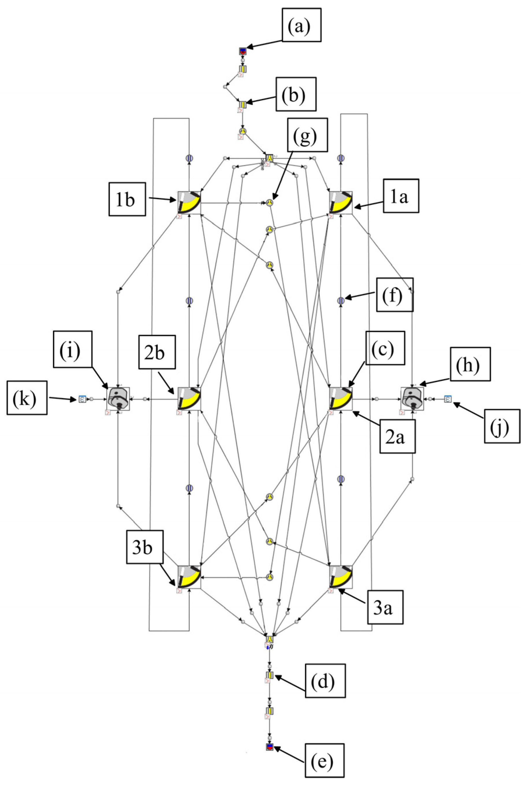
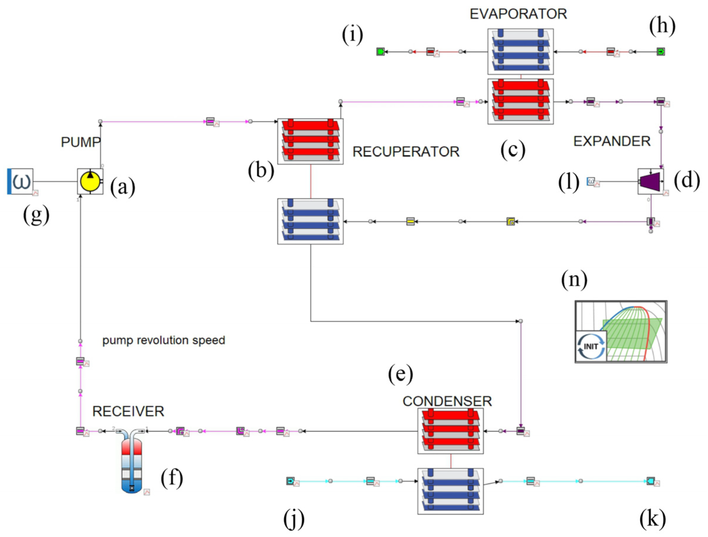
2.3. ORC-Based Power Unit Model

Once the Single Intake Port (SIP) Scroll expander model was validated, it was used as a software platform GT-Suite™ 2022 to assess the expander performance when Dual Intake Port (DIP) was introduced. Subsequently, an operating map has been derived for a wide operating range and introduced in the comprehensive model of the ORC-based power unit according to the approach presented in [25]. The model was developed in [26] where more details can be found. In this paper, only the main properties were reported focusing on the novel aspect related to the integration of the SIP Scroll expander model with that of the main ORC-based power unit.
The structure of the ORC-based power unit model is reported in Figure 7. The pump (a) was modeled through a look-up table, similarly to that of the expander (d) [26]. The Heat Recovery Vapor Generator (HRVG) (c), the recuperator (b) and the condenser (e) have been modeled through physical model solving the conservation equations following the same approach presented in [26].
Figure 7. ORC-based unit model.
Energies 17 01021 g007
One of the most important aspects for the heat exchanger modeling concerns the heat transfer correlations used which fix the heat transferred from one fluid to the other [27]. Dittus–Boelter [28] correlations are used in the case of fluids having a single phase (subcritical or supercritical). For two-phase fluids, Plate, Yan, Lio, Lin correlation [29] was used for the condensation, whereas Plate Kandlikar [30] was used for evaporation. Friedel correlation was used for pressure drop assessment [31]. A zero-dimensional approach for element (f) representing the 3 L plenum upstream of the pump while element (n), allows to consider the working fluid mass charge, initial conditions and a database to evaluate the thermodynamic properties of the fluids. The boundary conditions required by model are the following:
Pump speed. It is introduced through element (g) of Figure 7 and allows to set the desired mass flow rate with the pump being a volumetric machine.
The temperature and mass flow rate of the hot water at HRVG inlet (hot side). The data can be introduced through the element (h).
Pressure at HRVG outlet of the hot water. It can be introduced through element (i).
The temperature and the mass flow rate of the cold water at condenser inlet (cold side). The values can be introduced through element (j).
Pressure at condenser outlet (cold side). It can be set via element (k).
Similarly to what was done for the scroll expander, the relation between expander speed and working fluid mass flow rate was considered as boundary condition (through l element) also in this case.

3. Results

3.1. Experimental Validation

An experimental validation was performed based on data as reported in Table 2. As aforementioned, for the adopted layout, the expander speed cannot be externally controlled but it depends on the dynamic equilibrium of the machine shaft. Nevertheless, in accordance with authors’ previous work [26], the revolution speed linearly varies with mass flow rate, which is the main regulation quantity.
Mass flow rate varies from 32 g/s up to 54 g/s with intake pressure from 7.6 bar up to 10.7 bar. Despite the revolution speed being raised from 4590 RPM up to 5520 RPM, the expander permeability α, evaluated according to Equation (3), changes slightly around 0.06 kgMPa−1 s−1, so a constant value can be assumed. Permeability is defined as:
α = W F Δ p e x p
and represents the attitude of the expander (and consequently of the plant) to be crossed by working fluid. The higher is the permeability α, the larger is the working fluid mass flow rate ṁWF elaborated for a given pressure difference between expander intake and exhaust pressure Δpexp.
Thus, even if the expander speed is not externally fixed, the expander intake pressure follows a linear increase with mass flow rate growth. So, as the permeability results constant even if the scroll is free to rotate (0.06 kgMPa−1s−1), when the mass flow rate increases the pressure difference across the expander grows, boosting the power produced from 398 W at 4590 RPM up to 545 W at 5520 RPM.
The experimental validation shows that the model is satisfactorily able to reproduce the experimental behavior (Table 3), despite the simplifications that have been made in order to get a very reduced computational time, and so is usable for control purposes. As already observed, an operating map of the expander was derived and introduced for the whole ORC-based plant model-element (d) of Figure 7. The dataset reported in Table 4 is referred to the performance of the overall unit. In Figure 8a–c, the Ts diagrams of case 1, 3 and 5 are reported, respectively. Case 1 (Figure 8a) represents the situation in which the plant presents the highest maximum temperature and pressure leading to the maximum expander power production. Anyway, due to the high-power consumption of the pump, this case does not correspond to the maximum ORC power production which is achieved in case 3, reported in Figure 8b. In Figure 8c, case 5 is reported instead, where the lowest values of maximum cycle temperature and pressure are reached. In each cycle, 2 corresponds to condenser outlet/pump inlet, 3 to pump outlet/recuperator (cold side) inlet, 4 to recuperator (cold side) outlet/HRVG inlet, 5 to saturated liquid state, 5′ to saturated vapor state, 6 to HRVG outlet/expander inlet, 7 expander outlet/recuperator (hot side) inlet, 8 recuperator (hot side) outlet/condenser inlet, 9 saturated vapor state, and 1 saturated liquid state.
In Table 5, the errors between the experimental and theoretical data are reported. Concerning the working fluid mass flow rate, the maximum relative error is equal to −1.8% whereas for the maximum and minimum pressures, maximum relative errors are, respectively, equal to −2.7% and 10.5%. Maximum and minimum temperature are represented with an absolute error, respectively, equal to −5 °C and 9.6 °C. Hot side inlet and outlet temperatures at the regenerator are represented with an error equal to 5.7 °C and 4.5 °C, while the cold side outlet temperature presents a difference of 6.1 °C. As a conclusion, the overall model of the plant satisfactorily represents the main variables, which produce power and efficiency predictions with a maximum relative error of −14.7% and 10.7%, respectively. Starting from these modeling performances, the model was used to analyze the impact of the plant when two intake ports replaced the single one (Figure 6).
Figure 8. Temperature-specific entropy (T-s) diagram for case 1 (a), case 3 (b) and case 5 (c) of Table 4.
Energies 17 01021 g008

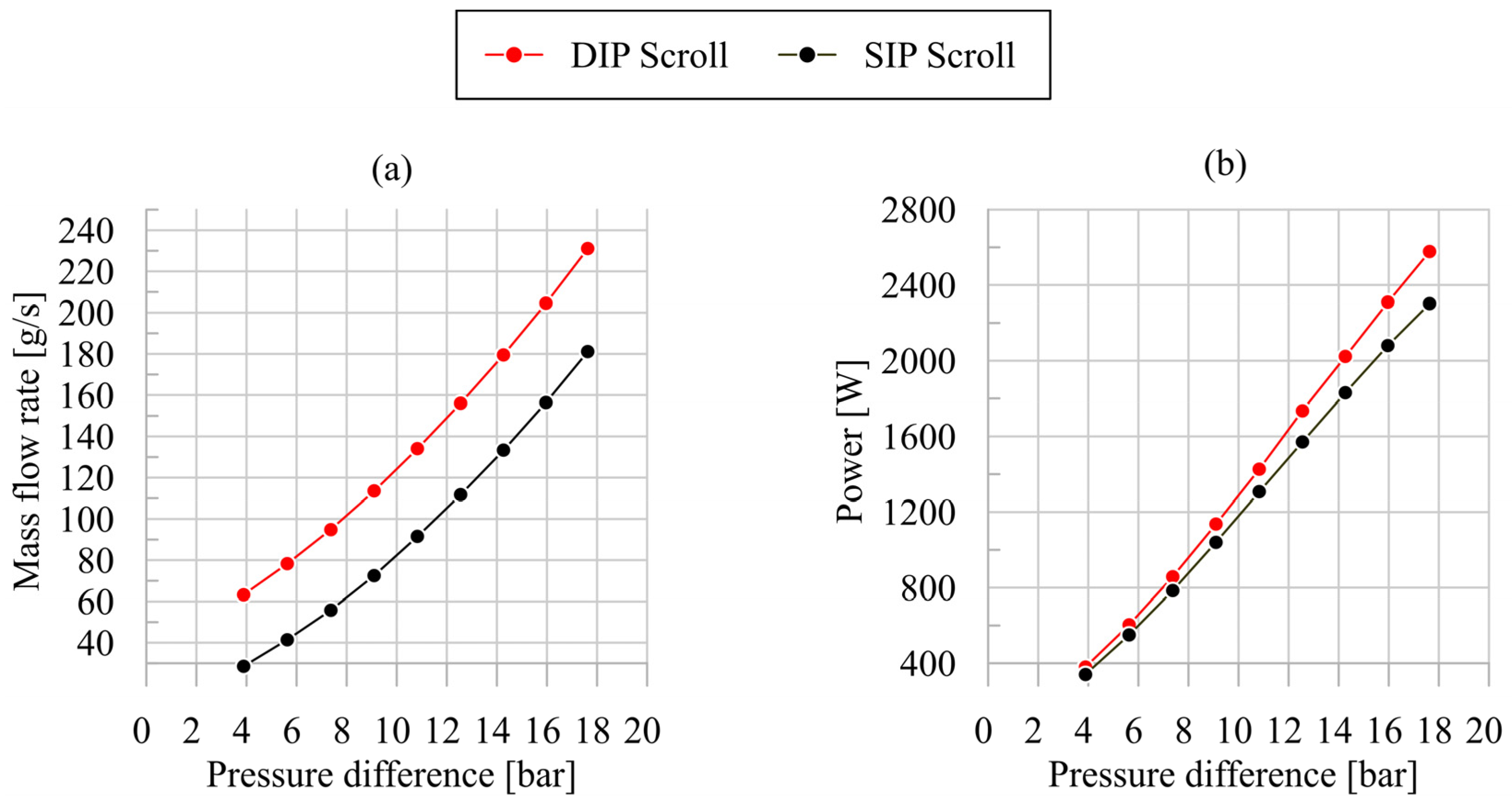
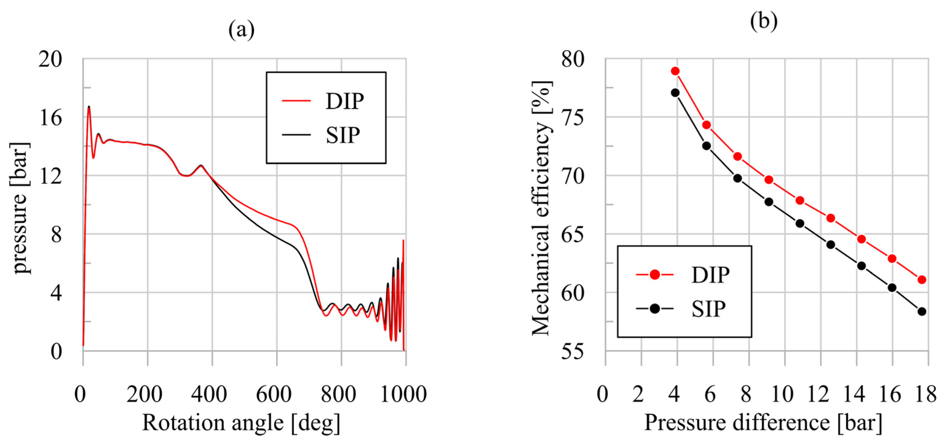
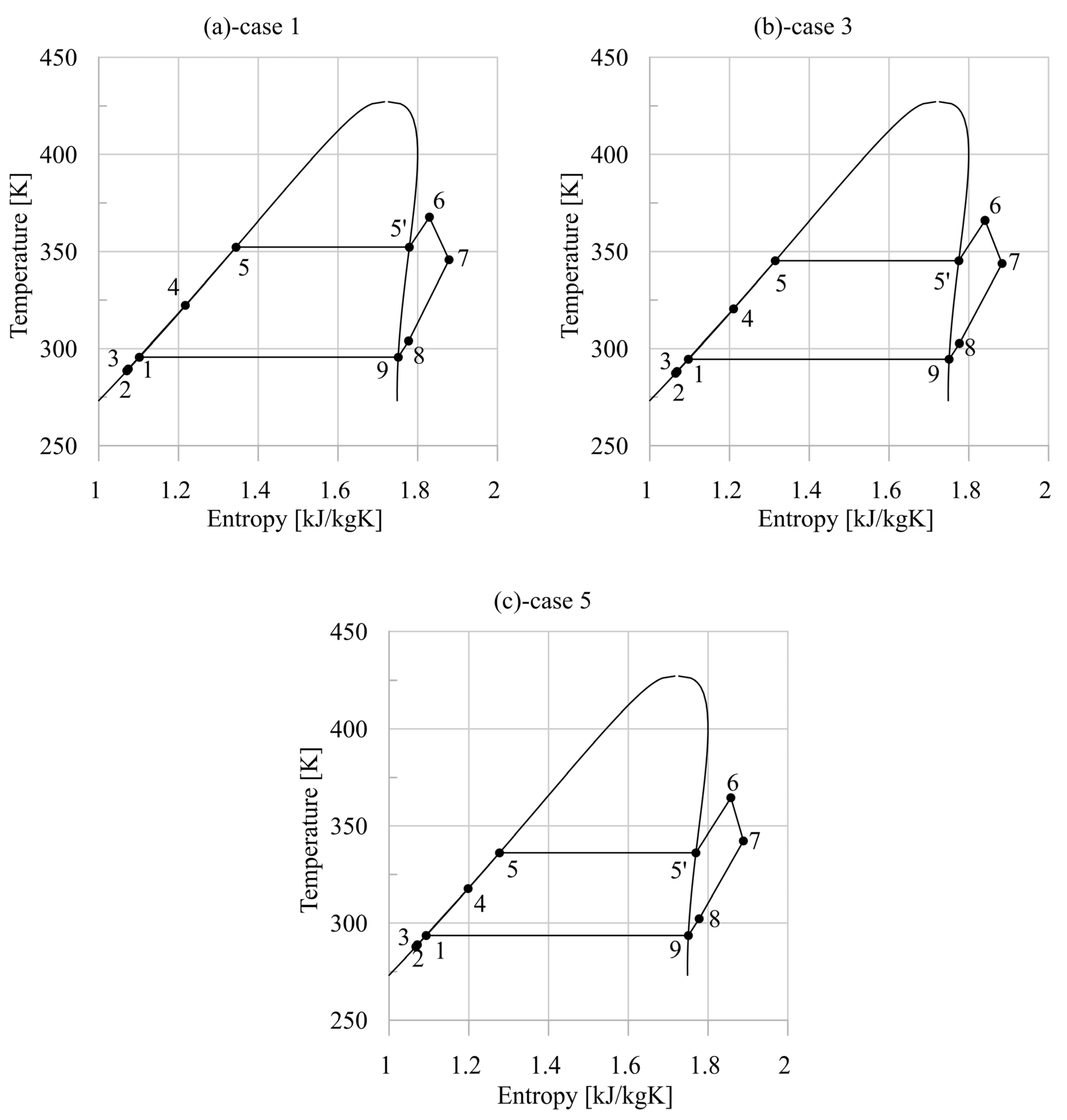
3.2. Impact of DIP Introduction on Expander and Plant Performance

Authors widely demonstrated experimentally and theoretically the benefits of the DIP technology when it is applied to SVRE [24]. In [24], they theoretically observed how for a scroll machine, the DIP introduction leads to an increase in performance, even though reduced with respect to SVRE, but the results were referred to a Waste Heat Recovery application characterized by a larger thermal power recovery [24]. The novel aspect treated by the present research is the suitability assessment of DIP when it is applied in an expander employed in a micro-scale (rated power of 500 W) power unit for domestic micro-cogeneration. These applications are characterized, as it is known, by a very low efficiency due to the low-grade thermal source (90–100 °C). Therefore, a small improvement is also particularly appreciated, resulting in the production of some additional electrical energy. The small dimensions of the expander, moreover, cast some doubts on the effectiveness of the double port. The effect on chamber filling, for instance, is not easily predictable considering that a bigger port could be more efficient than two smaller ports whose overall area is limited by the constraints previously observed. The passage of the spiral, moreover, should guarantee the sealing, considering that its thickness is greater than the diameter of the two ports, but some squeezing effect of the working fluid could be present and part of the mass inside the chamber can escape from it. For these reasons, a specific investigation has been performed.
The first analysis concerns the assessment of DIP impact on mass flow rate (Figure 9a) and scroll mechanical power increase (Figure 9b). As evident in Figure 9a, when the pressure difference across the expander increases, the mass flow rate aspirated by the expander increases too. This ensures the production of a higher power, as was expected (Figure 9b). For a pressure difference equal to 8, for instance, the mass flow rate increase is 32%, leading to a power gain of 9.4%. The higher permeability achieved (0.1 kg/(s·MPa)) with respect to a single intake port (0.06 kg/(s·MPa)) justifies the results. It is interesting to observe the high operational flexibility of the expander, which is able to deliver up to 2.5 kW (so a power level much greater than the rated one) when the pressure difference between inlet and outlet sections would be 18 bar. So, this performance reinforces the concept that for the power range of a few kW and in the presence of high off-design conditions (like, for instance, the thermal power available at the hot source), the best choice for the expander is a volumetric machine.
Figure 9. Mass flow rate (a) and mechanical power (b) of DIP and SIP scroll expanders as function of pressure difference.
Energies 17 01021 g009
Thanks to the higher mass flow rate introduced inside the machine, the indicated power (Equation (1)) increases, as is evident in Figure 10a. The pressure inside the vane as a function of rotation angle always remains greater in the case of a double intake port and, therefore, a greater work is transferred to the shaft. As claimed above, the real mechanical power Pmech of the scroll available for the electric generator depends on mechanical losses evaluated using the friction torque during the experimental validation. A linear dependence of the friction torque increase with pressure difference at the expander sides was seen. In Figure 10b, the mechanical efficiency has been reported (Equation (4)) where the benefits provided by DIP adoption can be seen.
η m e c = P m e c P i n d
This is since, in the case of a DIP technology, for a given pressure difference, the produced power is higher than in the SIP case (Figure 9b), whereas the power lost due to friction is about the same in the two cases (as it depends, basically, on the pressure difference). Hence, the impact of mechanical losses diminishes, leading to a growth of mechanical efficiency (Figure 10b). Therefore, the DIP technology not only allows to widen the operability range but also to improve the machine’s mechanical performance.
Figure 10. Indicated cycles (a) and mechanical efficiency as function of pressure difference (b) of DIP and SIP scroll expanders.
Energies 17 01021 g010
The comparison between the two intake technologies was performed considering the same intake and exhaust pressure which reports about the same mechanical stress for the expander. In the figures which follow, the intake temperature was the same at 10 °C as the superheating degree. It is evident how the power produced by the scroll (Figure 9b) increases along the whole range of inlet temperatures and pressures when a double intake port is considered, thanks to the larger mass flow rate elaborated (Figure 11a). The higher scroll performance leads to a higher net plant power production as shown in Figure 11b. It is evident how the net power differs from the previous results as, with the SIP scroll expander, the whole ORC unit power ranges from 250 W up to 550 W, whereas adopting the DIP machine, the whole power varies between 350 W and 650 W in the same operating range interval. So, an improvement of the order of 20–40% is achievable simply by doubling the suitably angularly placed intake port.
Therefore, the results show that for a given plant maximum pressure, the DIP expander can elaborate a higher working fluid mass flow rate (Figure 11a), thus leading to a greater output power (Figure 11b). Therefore, DIP Scrolls allow to enhance the energy recovery, keeping constant the maximum plant pressure. Indeed, to produce the same net power with a conventional scroll (SIP technology), the maximum plant pressure must be greater (and, consequently, the expander pressure difference being the downstream plant pressure fixed by the condenser conditions). To produce, for instance, a net power of 500 W, the DIP technology requires a maximum plant pressure equal to 8.8 bar, whereas a conventional scroll needs a value of 10 bar. A lower maximum plant pressure also ensures increased mechanical efficiency (Figure 10b).
Figure 11. Mass flow rate (a) and net ORC power as function of pressure difference (b) of DIP and SIP Scroll expanders.
Energies 17 01021 g011
Hence, DIP technology allows to produce high power for a given maximum pressure at the expander inlet. This is mainly due to the indicated efficiency improvement produced by the pV diagram (Figure 10a). But a not negligible further benefit is produced. Considering the unit tested, if, for instance, a threshold of 11 bar is considered as the maximum operating pressure, adopting the SIP machine, this limit is reached when 40 g/s of the working fluid is circulated. If the DIP technology is used, the same pressure threshold (11 bar) is reached with a working fluid mass flow rate higher than 60 g/s. This means that, besides the power gain achieved and shown in Figure 11, the DIP solution allows to keep the efficiency of the recovery unit close to a value of 5% (Figure 12), which is in line with the best literature results. Indeed, it is clear from Figure 12, having on the same expander the two possibilities (one port and two ports), the DIP “activation” allows to break the linear decrease in the efficiency when a SIP solution is considered (black line) occurring at 35 g/s. A flatter trend (red line) resulted if a DIP solution was switched on. Therefore, properly activating the DIP, the expander and, consequently, the plant can operate close to the design condition for a wider operating range.
Figure 12. ORC maximum pressure and efficiency as function of WF mass flow rate.
Energies 17 01021 g012

4. Conclusions

In the present paper, the feasibility assessment of the introduction of a double intake port (DIP technology) in a scroll expander for a micro-cogeneration power unit was performed. The advantages were quantified via a theoretical comparison made on a model experimentally validated in order to be sure that physical processes were correctly represented. The ORC-based unit was operated having, as hot source, the water inside a 150 L reservoir heated by two electrical resistances whose power delivered reproduced during a day the solar irradiation on 15 m2 flat plate solar collectors on a rooftop of a house in the center of Italy. The water inside the reservoir also acts as hot source for domestic hot water (DHW) production. A physically consistent model of the ORC-based unit which operates almost always in off-design conditions was properly simplified in order to behave as a model-based tool to set up a control strategy of the unit, optimizing thermal discharge of the reservoir and daily solar availability to recharge it. Special attention has been focused on the scroll behavior.
Once experimentally validated, the model of the scroll was used to evaluate its performance when the DIP technology is considered. The introduction of two ports, suitably located where the chambers perform the expansion phase, was performed and compared with those referred to the conventional solution with a unique port. The DIP technology allows to increase the machine’s permeability. So, for a given pressure difference at the expander sides, the DIP technology elaborates a higher mass flow rate (+32%), thus producing more power (+10%). A further improvement has been observed on the mechanical efficiency of the expander which increases in a share of 5% with respect to the conventional intake single port, due to the reduction in the impact of mechanical losses on the whole power that the DIP technology realizes. These features have the effect that the ORC-based power unit, for a given inlet pressure expander, boosts the power production. This is particularly suitable considering that these units have small overall efficiency due to the low-grade thermal energy (90–110 °C) which behaves as hot source.
Such results demonstrate how the adoption of DIP leads to an improvement of the performance even if the unit is fed by a low-temperature hot source. These results were not straightforward as the DIP was originally conceived by the authors for a Waste Heat Recovery application characterized by a higher grade of thermal power of the hot source. So, the advantages of the DIP technology (never studied) are also kept for very low temperatures of the hot sources, which are typical of different renewable applications. A key aspect of the success of DIP technology is the capability of it to elaborate a higher mass flow rate for a given pressure difference (with respect to the SIP technology) leading to a significant useful power gain. For the same mass flow rate crossing the expander, the maximum pressure of the unit (which depends on the permeability of the overall unit) is reduced when the DIP technology is adopted, with consequent benefits on the efficiency of the components, on their reliability, and also on their costs. Indeed, if the thermal power available for the unit grows (due, for instance, to a sudden reduction in DHW), the unit can increase the power produced via an increase in the working fluid flow rate (increasing the pump speed). A SIP configuration of the expander would produce unfeasible increases in the maximum pressure at the expander inlet while a DIP solution keeps a much lower value, due to the higher permeability of the plant it realizes with respect to the SIP solution.

Author Contributions

Conceptualization, F.F. and R.C.; methodology, F.F. and R.C.; software, F.F.; validation, F.F. and R.C.; formal analysis, F.F. and R.C.; investigation, F.F.; resources, R.C.; data curation, F.F. and R.C.; writing—original draft preparation, F.F. and R.C.; writing—review and editing, F.F. and R.C.; visualization, F.F. and R.C.; supervision, R.C. and F.F.; project administration, R.C.; All authors have read and agreed to the published version of the manuscript.

Funding

This research received no external funding.

Data Availability Statement

Data available on request.

Acknowledgments

The authors are grateful to SIVAM S.p.A and Sanden S.p.A for the support given for this activity.

Conflicts of Interest

The authors declare no conflict of interest.

Nomenclature

Symbols
dViinfinitesimal increase in i-chamber volume [m3]
mass flow rate [kg/s]
PPower [W]
ppressure [Pa]-[bar]
T Temperature [°C], [K]
tcycletime of a complete cycle [s]
Greek letters
α permeability [kg/(s·MPa)]
Δppressure difference [bar]
ηefficiency
ωexpander speed [rps]-[rpm]
Subscripts
expexpander
iinternal pressure i-chamber
in intake/inlet
ind indicated power
lossespower losses
mech mechanical
out exhaust/outlet
WFworking fluid
Acronyms
DHW Domestic Hot Water
DIP Dual Intake Port
ORCOrganic Rankine Cycle
HRVGHeat Recovery Vapor Generator
RHX Recuperative Heat Exchanger
SIP Single Intake Port
TES Thermal Energy Storage
WFWorking fluid

References

  1. Chatzopoulou, M.A.; Lecompte, S.; De Paepe, M.; Markides, C.N. Off-design optimisation of organic Rankine cycle (ORC) engines with different heat exchangers and volumetric expanders in waste heat recovery applications. Appl. Energy 2019, 253, 113442. [Google Scholar] [CrossRef]
  2. Manfredi, M.; Spinelli, A.; Astolfi, M. Definition of a general performance map for single stage radial inflow turbines and analysis of the impact of expander performance on the optimal ORC design in on-board waste heat recovery applications. Appl. Therm. Eng. 2023, 224, 119857. [Google Scholar] [CrossRef]
  3. de Oliveira Neto, R.; Sotomonte, C.A.R.; Coronado, C.J.R. Off-design model of an ORC system for waste heat recovery of an internal combustion engine. Appl. Therm. Eng. 2021, 195, 117188. [Google Scholar] [CrossRef]
  4. Cipollone, R.; Di Battista, D.; Bettoja, F. Performances of an ORC power unit for Waste Heat Recovery on Heavy Duty Engine. Energy Procedia 2017, 129, 770–777. [Google Scholar] [CrossRef]
  5. Aryanfar, Y.; Mohtaram, S.; Alcaraz, J.L.G.; Sun, H. Energy and exergy assessment and a competitive study of a two-stage ORC for recovering SFGC waste heat and LNG cold energy. Energy 2023, 264, 126191. [Google Scholar] [CrossRef]
  6. Mateu-Royo, C.; Mota-Babiloni, A.; Navarro-Esbrí, J.; Peris, B.; Molés, F.; Amat-Albuixech, M. Multi-objective optimization of a novel reversible High-Temperature Heat Pump-Organic Rankine Cycle (HTHP-ORC) for industrial low-grade waste heat recovery. Energy Convers. Manag. 2019, 197, 111908. [Google Scholar] [CrossRef]
  7. Rodriguez-Pastor, D.A.; Becerra, J.A.; Chacartegui, R. Adaptation of residential solar systems for domestic hot water (DHW) to hybrid organic Rankine Cycle (ORC) distributed generation. Energy 2023, 263, 125901. [Google Scholar] [CrossRef]
  8. Petrollese, M.; Cocco, D. A multi-scenario approach for a robust design of solar-based ORC systems. Renew. Energy 2020, 161, 1184–1194. [Google Scholar] [CrossRef]
  9. Ancona, M.A.; Bianchi, M.; Branchini, L.; De Pascale, A.; Melino, F.; Peretto, A.; Poletto, C.; Torricelli, N. Solar driven micro-ORC system assessment for residential application. Renew. Energy 2022, 195, 167–181. [Google Scholar] [CrossRef]
  10. Hasani, M.R.; Nedaei, N.; Assareh, E.; Alirahmi, S.M. Thermo-economic appraisal and operating fluid selection of geothermal-driven ORC configurations integrated with PEM electrolyzer. Energy 2023, 262, 125550. [Google Scholar] [CrossRef]
  11. Song, J.; Wang, Y.; Wang, K.; Wang, J.; Markides, C.N. Combined supercritical CO2 (SCO2) cycle and organic Rankine cycle (ORC) system for hybrid solar and geothermal power generation: Thermoeconomic assessment of various configurations. Renew. Energy 2021, 174, 1020–1035. [Google Scholar] [CrossRef]
  12. Braimakis, K.; Charalampidis, A.; Karellas, S. Techno-economic assessment of a small-scale biomass ORC-CHP for district heating. Energy Convers. Manag. 2021, 247, 114705. [Google Scholar] [CrossRef]
  13. Bao, J.; Zhao, L. A review of working fluid and expander selections for organic Rankine cycle. Renew. Sustain. Energy Rev. 2013, 24, 325–342. [Google Scholar] [CrossRef]
  14. Dumont, O.; Parthoens, A.; Dickes, R.; Lemort, V. Experimental investigation and optimal performance assessment of four volumetric expanders (scroll, screw, piston and roots) tested in a small-scale organic Rankine cycle system. Energy 2018, 165, 1119–1127. [Google Scholar] [CrossRef]
  15. Lemort, V.; Quoilin, S.; Cuevas, C.; Lebrun, J. Testing and modeling a scroll expander integrated into an Organic Rankine Cycle. Appl. Therm. Eng. 2009, 29, 3094–3102. [Google Scholar] [CrossRef]
  16. Mujic, E.; Kovacevic, A.; Stosic, N.; Smith, I. Advanced Design Environment for Screw Machines. In Proceedings of the International Compressor Engineering Conference, Purdue, IN, USA, 12–15 July 2010; p. 1971. Available online: https://docs.lib.purdue.edu/icec/1971 (accessed on 4 February 2024).
  17. Kovacevic, A.; Stosic, N.; Smith, I.K.; Mujic, E. Advances in Numerical Modelling of Helical Screw Machines. In Proceedings of the International Compressor Engineering Conference, Purdue, IN, USA, 12–15 July 2010; p. 1953. Available online: https://docs.lib.purdue.edu/icec/1953 (accessed on 4 February 2024).
  18. Leibowitz, H.; Smith, I.K.; Stosic, N. Cost Effective Small Scale ORC Systems for Power Recovery From Low Grade Heat Sources. In Proceedings of the ASME 2006 International Mechanical Engineering Congress and Exposition. Advanced Energy Systems, Chicago, IL, USA, 5–10 November 2006; pp. 521–527. [Google Scholar] [CrossRef]
  19. Bianchi, M.; Branchini, L.; Casari, N.; De Pascale, A.; Melino, F.; Ottaviano, S.; Pinelli, M.; Spina, P.R.; Suman, A. Experimental analysis of a micro-ORC driven by piston expander for low-grade heat recovery. Appl. Therm. Eng. 2019, 148, 1278–1291. [Google Scholar] [CrossRef]
  20. Mohd, M.; Tahir, N.Y.; Hoshino, T. Efficiency of compact organic Rankine cycle system with rotary-vanetype expander for low-temperature waste heat recovery. Int. J. Environ. Sci. Eng. 2010, 2, 11–16. [Google Scholar]
  21. Badr, O.; Naik, S.; O’Callaghan, P.W.; Probert, S.D. Expansion machine for a low power-output steam Rankine-cycle engine. Appl. Energy 1991, 39, 93–116. [Google Scholar] [CrossRef]
  22. Musthafah, M.T.; Yamada, N. Thermodynamic analysis of expansion profile for displacement-type expander in low-temperature Rankine cycle. J. Therm. Sci. Technol. 2010, 5, 61–74. [Google Scholar] [CrossRef]
  23. Vodicka, V.; Novotny, V.; Zeleny, Z.; Mascuch, J.; Kolovratnik, M. Theoretical and experimental investigations on the radial and axial leakages within a rotary vane expander. Energy 2019, 189, 116097. [Google Scholar] [CrossRef]
  24. Fatigati, F.; Di Bartolomeo, M.; Cipollone, R. Dual intake rotary vane expander technology: Experimental and theoretical assessment. Energy Convers. Manag. 2019, 186, 156–167. [Google Scholar] [CrossRef]
  25. Fatigati, F.; Di Giovine, G.; Cipollone, R. Feasibility Assessment of a Dual Intake-Port Scroll Expander Operating in an ORC-Based Power Unit. Energies 2022, 15, 770. [Google Scholar] [CrossRef]
  26. Marchionni, M.; Fatigati, F.; Di Bartolomeo, M.; Di Battista, D.; Petrollese, M. Experimental and Numerical Dynamic Investigation of an ORC System for Waste Heat Recovery Applications in Transportation Sector. Energies 2022, 15, 9339. [Google Scholar] [CrossRef]
  27. GT-SUITE-Flow Theory Manual; T Gamma—Gamma Technologies Inc.: Westmont, IL, USA, 2020; Available online: https://www.gtisoft.com/ (accessed on 1 December 2023).
  28. Dittus, F.W.; Boelter, L.M. Heat transfer in automobile radiators of the tubular type. Int. Commun. Heat Mass Transf. 1985, 12, 3–22. [Google Scholar] [CrossRef]
  29. Yan, Y.-Y.; Lio, H.-C.; Lin, T.-F. Condensation heat transfer and pressure drop of refrigerant R-134a in a plate heat exchanger. Int. J. Heat Mass Transf. 1999, 42, 993–1006. [Google Scholar] [CrossRef]
  30. Kandlikar, S.G. A General Correlation for Saturated Two-Phase Flow Boiling Heat Transfer Inside Horizontal and Vertical Tubes. J. Heat Transf. 1990, 112, 219–228. [Google Scholar] [CrossRef]
  31. Friedel, L. Improved Friction Pressure Drop Correlation for Horizontal and Vertical Two-Phase Pipe Flow. Available online: https://www.semanticscholar.org/paper/Improved-Friction-Pressure-Drop-Correlation-for-and-Friedel/5e65d566aaeff9037a4918d6f60d742787ce0d4a (accessed on 1 December 2023).
Table 1. Uncertainty of the measurement instruments.
VariableSensor TypeMeasurement Uncertainty
TemperatureThermocouple±0.75 °C
PressurePressure transducers±1.5% of full-scale
Mass flow rate (R245fa)Coriolis Flow meter±0.15% measured value
Mass flow rate (water)Magnetic Flowmeter±0.5% measured value
PowerWattmeter±1% measured value
Table 2. Experimental performance of the scroll expander.
123456
pexp,in [bar]7.68.39.29.410.110.7
pexp,out [bar]2.12.32.42.52.62.8
Texp,in [°C]93981029599101
Texp,out [°C]717576667275
wf [g/s]32.036.040.745.049.054.0
Pexp [W]398447499486525545
ωexp [rpm]459049505250510054005520
Table 3. Errors between experimental and predicted data of the scroll expander.
123456
Relative errors [%]
WF mass flow rate ṁwf 7.506.067.542.903.451.09
Expander intake pressure pin, exp 0.53−2.91−0.251.622.642.01
Absolute errors [°C]
Expander exhaust temperature Texp,out 3.42.70.8−0.22.44.0
Table 4. Experimental quantities.
Experimental
Quantities
Units123456
Mass flow rateg/s50.745.941.449.317.823.0
ORC maximum pressurebar10.49.79.010.15.05.9
ORC maximum temperature°C108.0104.3105.9104.391.490.5
ORC minimum pressurebar1.51.51.41.51.21.3
ORC minimum temperature°C2020.217.82314.613.7
Temperature at RHX inlet (hot side)°C8265.676.778.369.267.7
Temperature at RHX outlet (hot side)°C3330.331.134.82928.4
Temperature at RHX outlet (cold side)°C53.344.250.353.044.642.9
Expander powerW583565546563271347
Pump powerW2231791422091533
ORC unit powerW360386404354256314
Table 5. Errors between experimental and theoretical data.
Errors123456
Mass flow rate [%]−1.0−0.9−1.3−0.4−1.6−1.8
ORC maximum pressure [%]−1.9−0.1−0.2−2.7−2.1−1.8
ORC maximum temperature [°C]−1.62.51.6−5.00.80.7
ORC minimum pressure [%]1.5−1.20.6−4.99.310.5
ORC minimum temperature [°C]5.34.56.62.18.29.6
Temperature at RHX inlet (hot side) [°C]−1.85.72.0−5.32.92.3
Temperature at RHX outlet (hot side) [°C]4.24.24.50.52.53.3
Temperature at RHX outlet (cold side) [°C]2.06.14.3−1.86.97.3
ORC unit power [%]−5.4−3.8−10.0−11.7−12.7−14.7
ORC efficiency [%]4.42.59.211.49.010.7
Disclaimer/Publisher’s Note: The statements, opinions and data contained in all publications are solely those of the individual author(s) and contributor(s) and not of MDPI and/or the editor(s). MDPI and/or the editor(s) disclaim responsibility for any injury to people or property resulting from any ideas, methods, instructions or products referred to in the content.

