1. Introduction
The expansion of Renewable Energy Sources (RESs) such as Wind Turbines (WTs) and Photovoltaic (PV) is essential in response to the implementation of energy policies worldwide to address climate change. Some advanced nations are intensifying their reliance on RESs and are actively promoting these initiatives through their energy policies [
1]. In 2021, 195 countries signed the Paris Agreement and updated their Nationally Determined Contributions (NDCs). Nations such as the United States, Canada, the United Kingdom, and South Korea have set ambitious NDC goals of 52%, 45%, 68%, and 40%, respectively [
2]. These commitments are pivotal in augmenting the role of RESs in each country’s energy composition. Emphasizing its goal for carbon neutrality by 2050, South Korea is particularly focused on expanding its RES utilization [
1]. Moreover, many countries are implementing Renewable Portfolio Standards (RPS) and issuing Renewable Energy Certificates (RECs) to foster investment in renewable energy from the private sector.
Typically, RES installations encompass PV and WT systems, which convert natural, clean energy sources into electrical power [
3]. Policymakers, especially those targeting carbon neutrality, face the challenge of increasing the contribution of RESs in energy generation while reducing dependency on thermal power. One of the main difficulties is the precision control of the output from PV and WT systems, as they do not rely on conventional, controlled fuel inputs. This aspect can potentially lead to the destabilization of the power grid when RES generation exceeds immediate energy demand, leading to complications such as the Duck curve phenomenon, negative pricing, and the curtailment of RES output [
4,
5,
6]. This underscores the notion that surpassing certain levels of RES generation not only presents investment challenges but also technical hurdles.
Various technologies have been applied to prevent power imbalances caused by the output control of RESs. One of the methods to supplement the uncertain RES output proposed herein is to link the RESs to a battery energy storage system (BESS). The output of RESs is intermittent, which can lead to power imbalances. Therefore, in the event of an unexpected excess power supply, it is possible to alleviate the surplus power supply of RESs by storing electricity using the BESS. As a result, linking BESS can significantly improve the utilization rate and stability of renewable energy. In the reference [
7], the degree of curtailment for WT was analyzed using a BESS based on a two-stage optimization technique. Battery Energy Storage Systems (BESSs) are widely used not only for alleviating curtailment but also for frequency regulation. Therefore, the utilization of BESSs in the output control of Renewable Energy Sources (RESs) is considered to be a very important factor that will continue to play a significant role. However, due to the clear technical and economic limitations of BESS, there are difficulties in securing large-scale energy flexibility. A major issue is that BESSs cannot charge and discharge simultaneously, so if it continuously remains in charging mode during periods of concentrated RES output, it may require excessively large BESS capacity beyond what is necessary, leading to overinvestment. To solve these problems, the Power to Gas (P2G) technology is recently gaining attention. P2G is an energy management system consisting of an Electrolyzer (ELZ), a Hydrogen Energy Storage System (HESS), and a Fuel Cell (FC). When a power imbalance due to the sudden output fluctuations of RES is anticipated, the ELZ utilizes surplus electricity to produce hydrogen energy through water electrolysis, which is then stored in the HESS [
8]. The hydrogen stored in the HESS is supplied to the FC, where it is converted back into usable electrical and thermal energy. The power generation using FC contributes to carbon neutrality as it falls under clean hydrogen production [
9]. P2G technology has been validated through extensive research, and in South Korea, the use of hydrogen energy is being actively adopted due to laws and policies. Currently, the P2G technology, specifically the hydrogen produced from ELZ, tends to have a high amount of energy that cannot be utilized efficiently as it passes through HESS and FC due to efficiency losses. However, as mentioned earlier, if all excess power supply is mitigated using BESS, it would require a high capacity of BESS, which, despite the normal operation of RES, could lead to economic losses. Therefore, this paper considers the introduction of P2G technology to have significant advantages from this perspective.
The enactment of the “Hydrogen Law” by the South Korean government, alongside the initiation of the Clean Hydrogen Portfolio Standard (CHPS), has been pivotal in promoting the generation of clean hydrogen and fostering investments from the private sector in this field [
10]. There has been significant research into refining operational methods and enhancing the grid integration of P2G technology. For instance, Reference [
11] delves into how the operational capacity of P2G facilities influences the power loss and capacity factor in PV systems, thereby underlining the essential role of P2G in augmenting PV integration. Within the Swiss context, Reference [
12] illustrates the reduction in PV system curtailment when P2G is integrated, depending on the operational mode of the system. In a related study, Reference [
13] explores the integration of PV systems with P2G, aiming to avert the output saturation in PV and enhance the overall generation efficiency. Additionally, Reference [
14] demonstrates that utilizing a P2G-based Integrated Energy System can lead to a substantial reduction in curtailment for both WT and PV systems. Reference [
15] is focused on identifying the ideal capacity of P2G facilities for the deployment of RESs, offering a model to adjust the capacity of P2G facilities accordingly. The advancements and further studies in the field of P2G technology are documented in References [
16,
17].
The energy coupling system proposed in this paper includes both BESS and P2G technologies. This paper reduces economic and energy operational losses caused by RES through the combination of BESS and P2G technologies. Many studies analyze the impact of integrating P2G and BESS from the perspective of grid operators. However, the actual operators of RESs are Renewable Energy Providers (REPs), and therefore, this paper considers REPs as the investing entities in BESSs and P2G. By analyzing the benefits that REPs can gain with the increasing penetration of RES, this paper can propose the expected effects of BESS and P2G technologies.
This paper employs Stochastic Programming (SP) with empirical data to account for the uncertainty in RES output. The optimization programming is based on Mixed Integer Linear Programming (MILP). SP is applied as a method to address uncertainties, and numerous studies have been conducted to deal with uncertainty. Reference [
18] proposes a novel robust decentralized charging strategy for large-scale EV fleets and applies uncertainty set-based robust optimization based on Second-Order Cone Programming (SOCP) as a measure to cope with uncertainty. Reference [
19] applies multi-stage robust optimization for the optimization of a multi-energy coupled system.
The main contributions of this paper are as follows:
Integrated Energy Management: By combining BESS and P2G technologies, this paper proposes a holistic approach to mitigate the adverse effects of surplus RES generation. This integrated system not only enhances the stability of the power grid but also optimizes the energy utilization rate, showcasing a viable solution to the challenge of intermittent Renewable Energy Sources.
Economic and Operational Efficiency: The simulation results presented herein offer a detailed analysis of the economic and operational benefits of the proposed energy coupling system. By reducing the curtailment of RESs and improving the benefit structure for REPs, the paper underscores the potential for significant advancements in renewable energy management.
Stochastic and MILP-based Optimization: Employing Stochastic Programming (SP) alongside Mixed Integer Linear Programming (MILP), the paper addresses the output uncertainty of RESs, presenting a robust framework for energy system optimization. This methodological approach contributes to the precision and reliability of the discussed energy management strategies.
Policy and Technological Implications: The paper discusses the current legislative and policy frameworks that support the adoption of clean energy technologies, particularly highlighting South Korea’s initiative through the “Hydrogen Law” and the Clean Hydrogen Portfolio Standard (CHPS). The analysis of P2G’s role within this context provides valuable insights into the policy-driven adoption of renewable energy technologies.
Future Research Directions: Recognizing the limitations of current models, particularly in terms of temperature control and real-time operation optimization, the paper lays the groundwork for future studies. It emphasizes the need to explore sophisticated modeling techniques, such as the joint estimation of state of charge and temperature, and to consider the implications of multi-objective problems when additional actors like ISOs or facility investors are involved.
2. System Composition
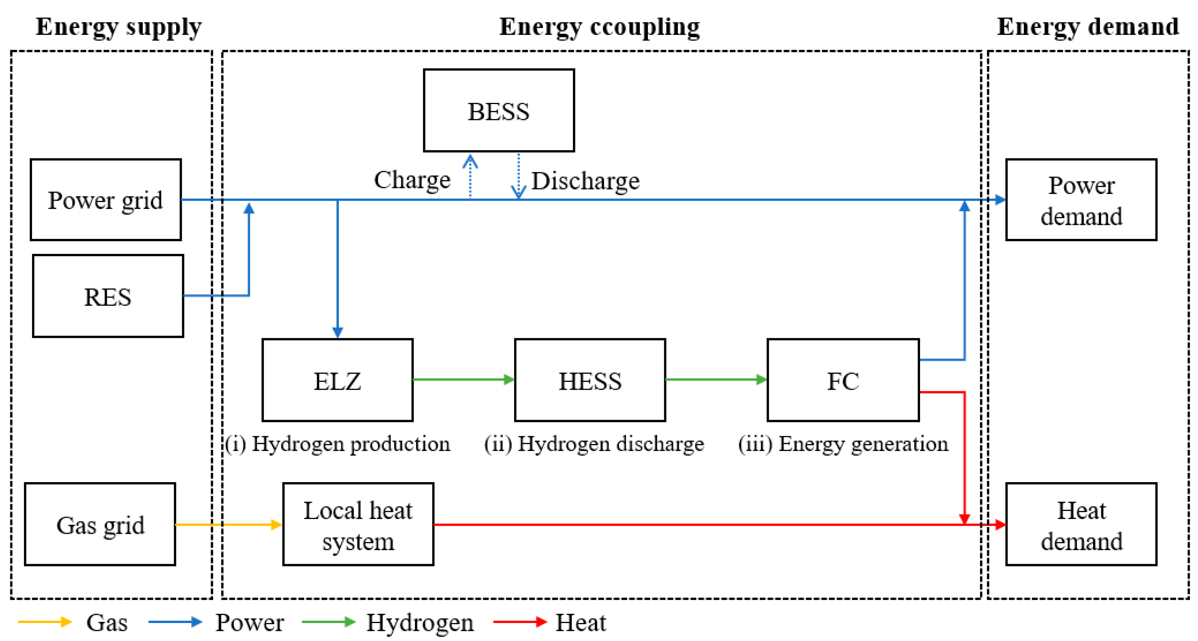
Figure 1 illustrates the topology of the P2G-linked energy system.
Figure 1, in this paper, displays the diagram of the proposed energy coupling system. The power supply is sourced from the power grid and RES, and in a single energy system, where there are no facilities for storing or converting electricity, excessive power supply compared to demand can lead to curtailment orders for the RES, with certain RES facilities being shut down. In contrast, in an energy coupling system, when the power supply exceeds demand, BESS and P2G technologies can be used to store electricity or convert it into hydrogen for efficient energy management. The operation of BESS and P2G technologies requires the application of optimization techniques. As shown in
Figure 1, the P2G technology involves storing hydrogen produced by ELZ in a HESS, and the stored hydrogen is then re-supplied as a controllable energy source through FC.
Given the numerous facilities discussed in this paper, additional heat supply through heat exchangers is possible; however, this requires the establishment of additional heat storage and supply devices. As this paper focuses on methods to compensate for the output uncertainty of RES, it is assumed that the sources of thermal energy supply are limited to local heat systems and FCs.
2.1. Modeling of RES
In this paper, RESs refer to WT and PV systems, and their equations are represented by Equations (1) and (2), as described in reference [
20].
In this paper, the representation of WT is as shown in Equation (1), which is a linear equation that takes into account realistic output ranges using parameters such as cut-in rate and cut-off wind speeds. refers to the rate power of WT, and and refer to cut-in wind speed and rate wind speed. In the Equation (2), refers to the capacity of PV, and refers to the standard temperature of the PV cell. The outputs of both WT and PV are derived based on empirical data related to wind speed and solar radiation.
2.2. Modeling of ELZ
ELZ can be classified into various modules depending on the catalyst, and we utilize a Proton Exchange Membrane (PEM)-based ELZ due to its high flexibility in output variation. In this paper, we additionally apply switch control constraints to the ELZ to prevent equipment lifespan reduction caused by frequent switching operations and ensure stable hydrogen production [
21,
22].
In Equations (4) and (5), represents a binary variable indicating the operational status of the ELZ, applied for the switch control mode constraint. When bELZ is 0, ELZ is non-operational, and when it is 1, the ELZ usually operates. M denotes a huge arbitrary number. The M refers to the big M, and T refers to the total time step.
2.3. Modeling of FC
The FC employs a Solid Oxide Fuel Cell (SOFC) module, known for its superior power efficiency, and is formalized as Equations (8)–(11) [
22].
In these equations, and refer to the power and the heat efficiency of FC.
2.4. Modeling of HESS
In this paper, HESS is modeled as described in Equations (12) and (13) [
14]. HESS applies Type 4 modules capable of storing hydrogen on a large scale at an atmospheric pressure of 700 bar. Type 4 tanks for HESS are justified by their high-pressure storage capabilities, lightweight, safety features, durability, environmental benefits, and compliance with regulatory standards. These characteristics make them ideally suited for modern hydrogen storage applications, supporting the transition towards cleaner energy solutions and the efficient utilization of Renewable Energy Sources.
Equations (12) and (13) describe the P2G operation process and are connected to the models of ELZ and FC. The charging and discharging logic of HESS is deeply associated with ELZ and FC. The hydrogen generated in Equation (3) acts as the hydrogen energy being charged in Equation (12), and conversely, the hydrogen energy discharged in Equation (12) serves as the hydrogen fuel used for power generation in FC, as described in Equations (8) and (9). Through this process, the hydrogen conversion logic among ELZ–HESS–FC is established.
2.5. Modeling of BESS
In this paper, BESS is modeled as described in Equations (14)–(20) [
14]. BESS is easy to charge and discharge, and it is assumed to use lithium-ion batteries, which are commonly utilized as power BESS. Lithium-ion batteries are favored for BESS due to their high energy density, allowing compact storage, high efficiency with minimal energy loss, long lifespan with thousands of charge-discharge cycles, quick charging and discharging capabilities crucial for grid stability, scalability, and environmental improvements through recycling advancements, all supported by their market maturity and cost-effectiveness.
Equation (14) defines the state of charge (SOC) for the BESS, considering its charging and discharging activities. To prevent the BESS from exceeding its capacity, Equations (16) and (17) are employed to restrict the immediate charging and discharging quantities. It is important to note that a BESS cannot charge and discharge simultaneously. This necessitates using binary variables to signify the operational status for each activity, which are incorporated into the charging and discharging variables. However, directly applying binary variables to Equation (14) would complicate the equation, making it non-linear. To maintain linearity and comply with MILP standards, Equations (18)–(20) are utilized.
3. Energy Flow
The energy coupling system proposed in this paper applies both power flow and gas flow. The power flow analysis of the electricity system is approached through Distflow, and the formulation of nonlinear equations is presented succinctly as depicted in Equations (21)–(25) [
23]
In Equations (21) and (22), the indices and respectively refer to the previous bus, the reference bus, and the next bus concerning bus . and represent active and reactive power consumption at each bus. The refers to the set of each bus. Equations (21) and (22) denote the power balance equations for active and reactive power, respectively. Since this paper focuses on the energy flow analysis of steady-state radial distribution systems without additional equipment, the backward transmission of , and is assumed to be 0. In the Equation (23), represents the voltage variation equation, and Equation (24) signifies the voltage drop formula due to voltage fluctuations. The and refer to the resistance and the reactance, respectively. Regarding Equation (25), it is inherently nonlinear and necessitates linearization within the optimization equation. However, due to the relatively straightforward nature of nonlinear equations in electricity systems, a simple linear approximation is adequate to attain swift and dependable outcomes.
Gas flow encompasses a multitude of equations employed in commercial applications, yet the interpretation of flow based on the square of pressure remains uniform. For this study, the extensively acknowledged Weymouth equation is adopted as the reference technique [
24]. Equation (26) encapsulates the nonlinear Weymouth equation.
In Equation (27),
and
respectively, represent the pressures of natural gas, while w0 to w4 stand for the constants utilized within the Weymouth equation.
and
denote the efficiency factor and the inside diameter of the pipe, respectively.
and
correspond to the absolute temperature and absolute pressure,
and
refer to the specific gravity of gas in the pipeline, the pipeline length between points m and n, temperature, and compressibility factor. For a more comprehensive understanding of the parameters within the Weymouth equation, refer to [
24]. Equation (13) presents the equation for pressure drop derived by substituting the parameter
.
3.1. Optimization Methodology
3.1.1. Logic of Energy Coupling System
Equations (28)–(30) describe the operational logic of the P2G-linked energy system from a power balance perspective.
Equations (28) and (29) aggregate the outputs of each WT and PV facility, denoted by
and
, respectively. The variables
and
indicate the operational states of each facility. A value of 0 for these variables signifies that the corresponding facility is curtailed, whereas a value of 1 denotes normal operation. Equation (30) represents a power balance formulation that incorporates the storage and conversion equations for power based on BESS and P2G technologies.
Equation (31) accounts for the heat demand by representing the heat supplied by the FC to meet local heat requirements. In other words, the operation of the FC depends on the constraint of heat demand. The refers to the supplied heat from the local heat system.
3.1.2. Objective Function
Equation (32) represents the objective function of the optimization model proposed in this paper.
In Equation (32),
,
, and
and
and
represent the benefit and cost of each facility, respectively, and the detailed formulas can be found in Equations (33)–(37).
In Equations (33)–(37), Equation (33) pertains to the total benefit of the RES. The benefit of RES signifies the settlement money received by trading the outputs of WT and PV, which is ultimately determined by the REC received for each output and the System Marginal Price (SMP) applied in aggregate. Thus, the decision variables are the outputs of WT and PV, with REC and SMP acting as parameters. Equation (34) refers to the total benefit of P2G. The benefit of P2G denotes the settlement money received by trading the electricity and thermal energy generated through the FC, expressed by adding the benefit received through the REC and integrated SMP for the FC’s electricity to the benefit from selling the FC’s thermal energy. Hence, the decision variables are the electric and thermal outputs of the FC, with REC, SMP, and the cost of selling thermal energy serving as parameters. Equation (35) relates to the total benefit of the BESS. The benefit of the BESS signifies the settlement money received by trading the electricity supplied through the BESS, settled through the discharged output and the BESS’s REC and integrated SMP. Thus, the decision variable is the discharge output of the BESS, with REC and SMP acting as parameters. Equation (36) represents the capital cost information of the BESS. In Equation (37), represents the set of facilities related to P2G, which includes the ELZ, the FC, and the HESS, as described in this paper. In the cost calculation formula, the decision variables are the capacities of each facility, with installation and operational costs acting as parameters.
3.1.3. Stochastic Programming
In this paper, we address the uncertainty in RES output by integrating SP into the optimization model. The SP approach proposed in this paper is grounded in statistical analysis using empirical data from WT and PV systems. We derive data distributions tailored to different seasons and times, encompassing ranges that account for the potential data inaccuracies. Subsequently, we implement Monte Carlo Simulation (MCS) through repeated iterations. MCS applies to data generated based on the upper and lower bounds of data that have a 15% standard error based on the expectation value of each probability distribution generated through empirical data. Through this process, it is possible to consider the output errors of PV and WT, which deviate from deterministic data, and since the uncertainty model is based on the MCS, it is possible to derive both the minimum and maximum results according to the uncertainty of PV and WT outputs. The numerical results of this paper are based on the average values derived through the MCS. Equations (38)–(40) formulate the power balance, incorporate RES output data into the simulation, and account for the principles of SP.
Figure 2 illustrates examples of the lower and upper bounds for the 24 h outputs of PV and WT systems.
In Equations (38)–(40),
represents random data within the error from each data distribution. As a result, the proposed optimization model in this paper is formalized with the application of SP, while maintaining the objective function, as shown in Equation (41).
Since Equation (41) includes random data, we obtain the optimal solution by using the MCS to derive the expected value.
4. Simulation Results
4.1. Basic Data and Scenarios
Table 1 presents the economic parameters and efficiency of each facility applied in this paper.
The demand information applied in the simulation of this paper is shown in
Table 2.
In this paper, the RES discussed are limited to WT and PV. The total capacity of the WT is 2700 kW and that of the PV is 5400 kW. The capacity information for each facility is shown in
Table 3.
The scenarios in this paper are classified as follows: single energy system and energy coupling system.
The results for each scenario in this paper are augmented with outcomes based on variations in the proportion of renewable energy. The capacity in
Table 3 is taken as a 100% baseline, and by considering an increase of up to 150%, the paper suggests that the expected effectiveness of the energy coupling system is superior in anticipation of the increasing capacity of the RES over time. Additionally, the simulation time step is reconfigured to 876 h, considering the seasonal characteristics of each energy demand and RES output based on statistical data. The simulation utilizes the DOCPLEX solver, which is based on Python. This paper focuses on improving the uncertain benefit structure of the REP as the penetration of the RES increases through the energy coupling system. Accordingly, the consideration of uncertainty is limited to the output of RES, and electricity demand is assumed as deterministic data.
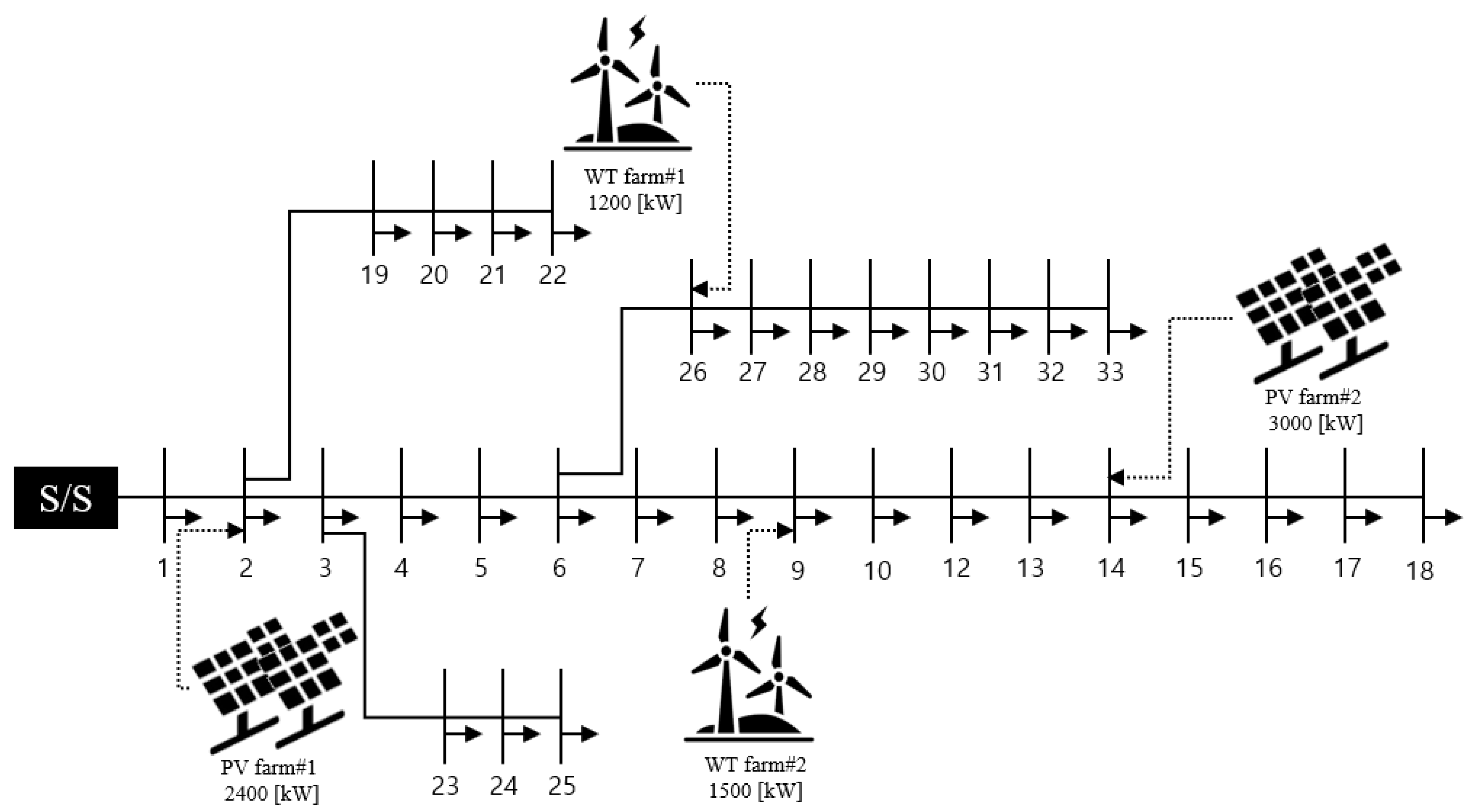
The research area is based on the IEEE 33-bus system, and the distribution of renewable energy is shown in
Figure 2. In the
Figure 2, dotted line represent the interconnection of RES.
4.2. Scenario 1: Single Energy System
The single energy system is a system where BESS and P2G technologies are not applied. In cases where a high output occurs compared to the electricity demand, the curtailment of RES happens, leading to a reduction in the economic benefits as the REP does not receive settlement payments.
Table 4 numerically presents the results of Scenario 1.
The results in
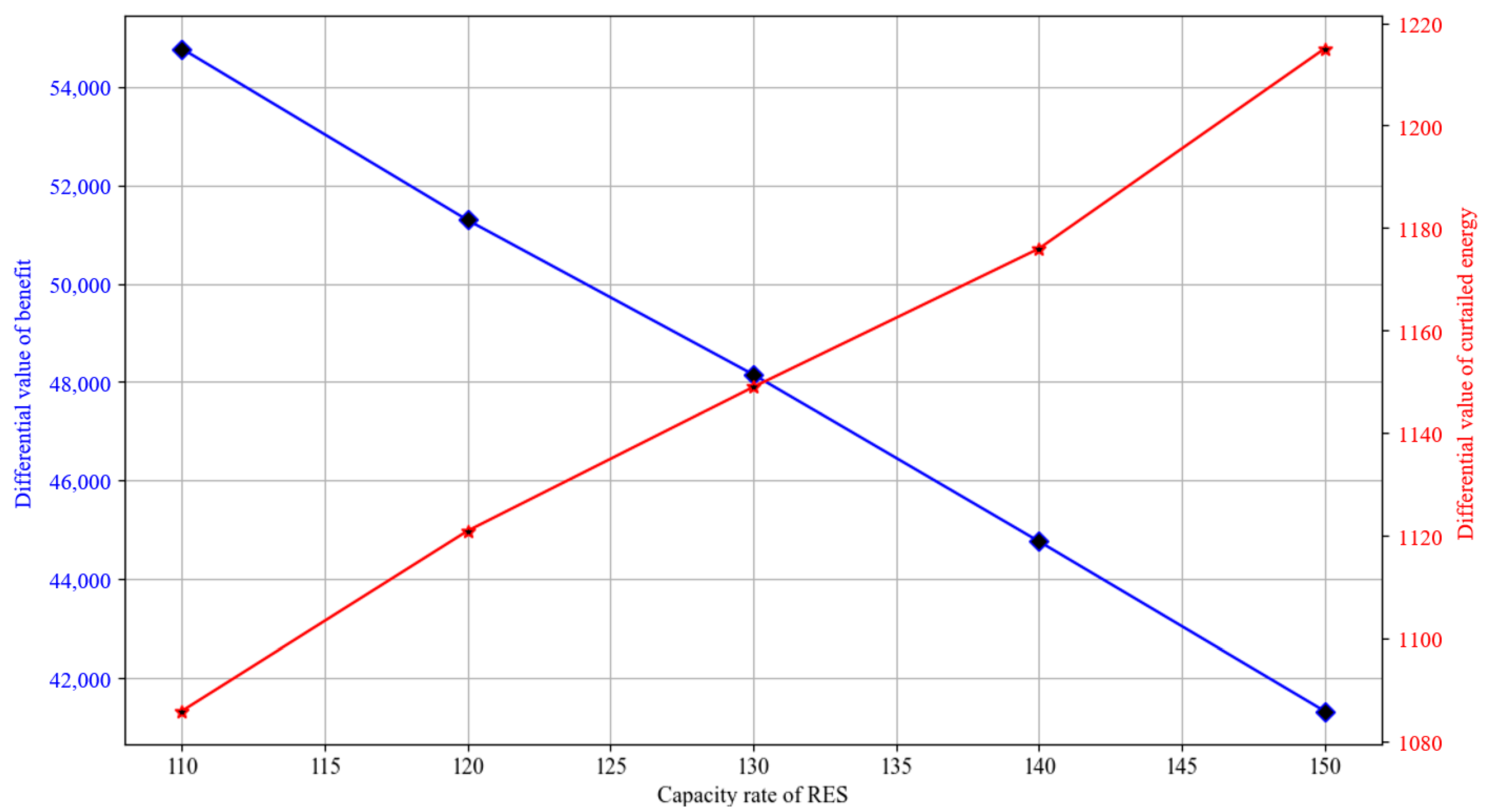
Table 4 show a trend where both the benefit and curtailed energy increase as the proportion of RES increases. However, the consistent increase in total curtailed energy implies that the benefit is not sufficient relative to the capacity owned by the REP. To illustrate this,
Figure 3 presents the differentiated values of the results, according to the RES proportion in Scenario 1.
As shown in
Figure 3, as the proportion of RES increases, the differentiated value of total curtailed energy increases, while the differentiated value of benefit decreases. This indicates that as the proportion of RES increases, the benefit that the REP can receive becomes less reasonable, ultimately leading to investment losses.
Figure 3 ultimately signifies that a single energy system cannot accommodate the expanding generation capacity of RES, necessitating continuous maintenance. As the capacity of RES increases, the differential value of curtailed energy rises, and the differential value of benefits decreases. This implies that continuously operating RES within a single energy system could lead to losses from both economic and energy operation perspectives in the long run. Through
Figure 3, we can validate the need for an energy coupling system.
4.3. Scenario 2: Energy Coupling System
The energy coupling system utilizes BESS and P2G technologies to flexibly utilize energy when the supplied power exceeds demand. Consequently, it reduces the curtailment of RES, thereby increasing the annual benefits of REP and improving the operational efficiency of RES.
Table 5 numerically presents the results of applying the energy coupling system with the increased proportion of RES.
In the case of Scenario 2, as shown in
Table 5, even including the costs of the facilities, it demonstrates the ability to secure high benefits for the REP, while drastically reducing the curtailed energy of RES.
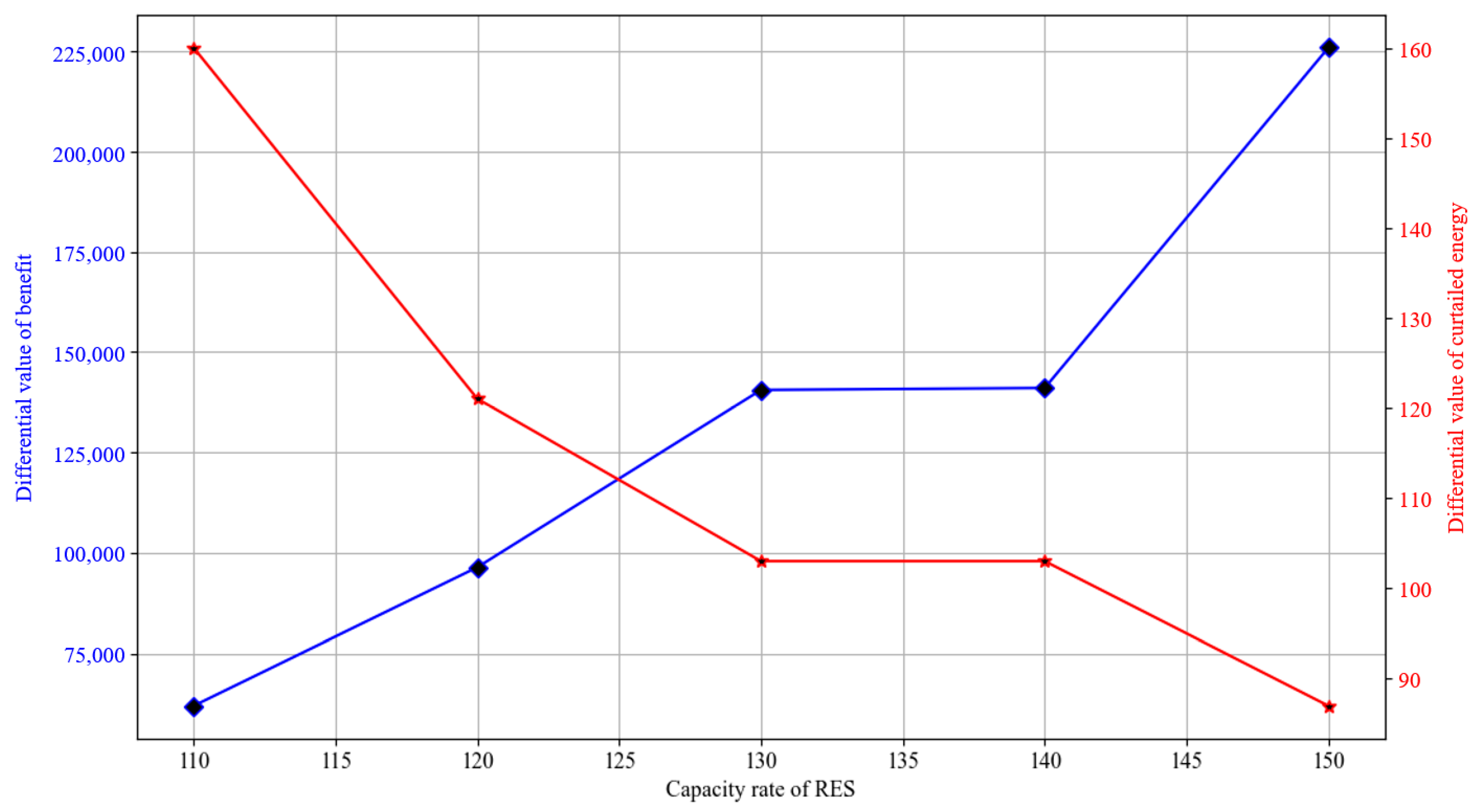
Figure 4 illustrates the trend of the derivative values of the benefits and curtailed energy in Scenario 2.
Contrary to Scenario 1, the derivative value of the benefit increases with the increasing proportion of RES, and the derivative value of curtailed energy decreases as the proportion of RES increases. This indicates that the energy coupling system performs better with a higher proportion of RES. Considering the mandatory expansion of RES facility proportion due to energy policies, the energy coupling system is proven to be economically and energy operationally efficient from a future-oriented perspective. The increase in the differential value of benefit and the reduction in the differential value of curtailed energy mean that the expected effects of the energy coupling system improve as the capacity of RES expands. This implies not only an immediate analysis of the current situation but also that, from a future-oriented perspective, the differential values can have a decisive impact on REP’s decision making regarding investments in the energy coupling system.
From these results, we can verify that it is reasonable to adopt the energy coupling system when considering the increasing proportion of the RES. Additionally, the optimal capacities of each facility derived from the optimization system allow us to determine the proportion of BESS and P2G facilities relative to the capacity of the RES. This can be applied as an economic analysis factor for investing in the energy coupling system project from the perspective of the REP.
Table 6 shows the proportion of the optimal capacity applied to each facility in the energy coupling system relative to the capacity of the RES. Among the P2G facilities, only the ELZ facility, which directly converts the output of RES, is applied.
As shown in
Table 6, the ELZ is selected as the optimal capacity at an average of 32.9% relative to the capacity of the RES, and the BESS is selected at an average of 38.5% relative to the capacity of the RES.
Table 6 can be used as an investment indicator for investing in the energy coupling system from the perspective of the REP. Using this, the REP can analyze the approximate scale of the required facilities and the investment cost of these facilities, thereby conducting an economic analysis.
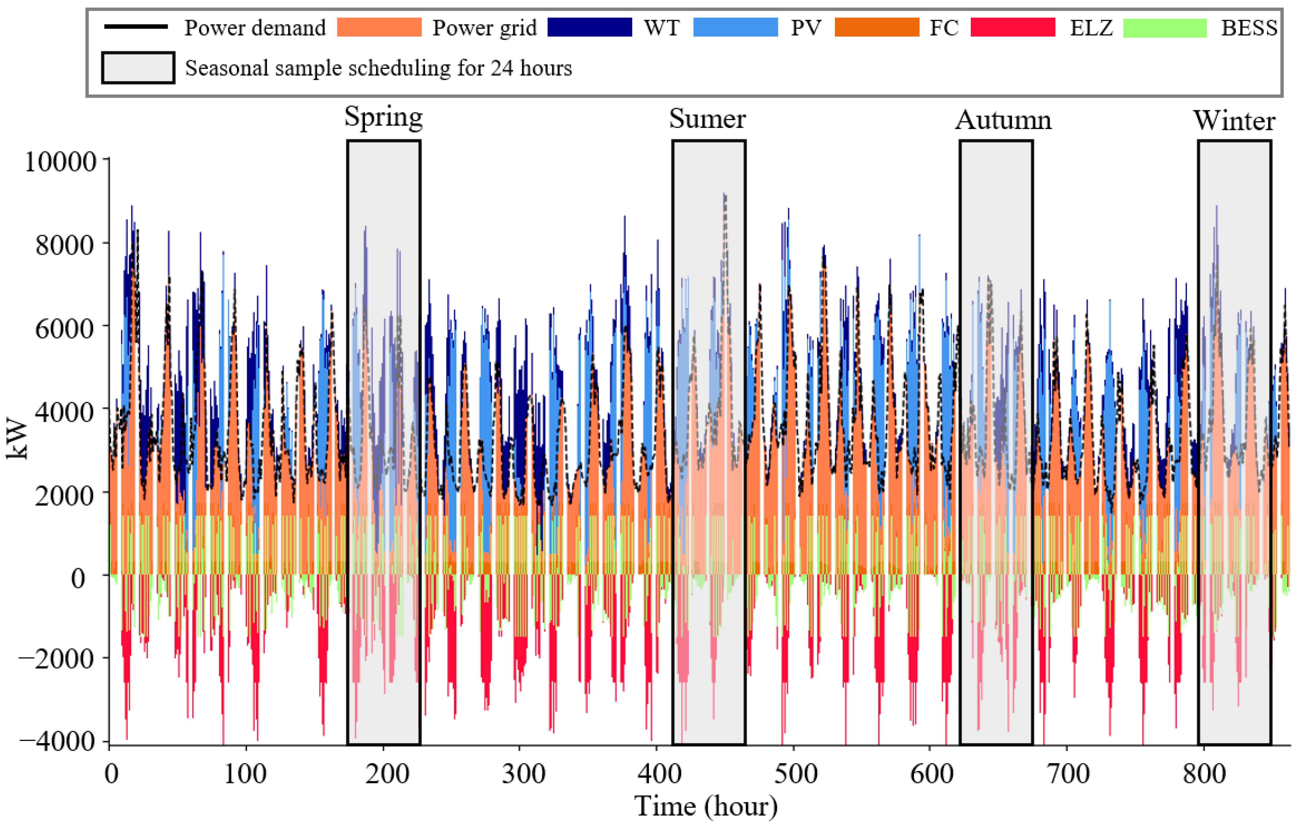
Figure 5 shows the optimal scheduling of the energy coupling system when the reference RES capacity is applied.
Figure 5 shows that the ELZ and the BESS operate intensively during times of high RES output and are less active during periods of high demand or low RES output. However, since it is difficult to analyze the detailed operational characteristics of the facilities from
Figure 5, this paper presents sample scheduling for 24 h in each season through
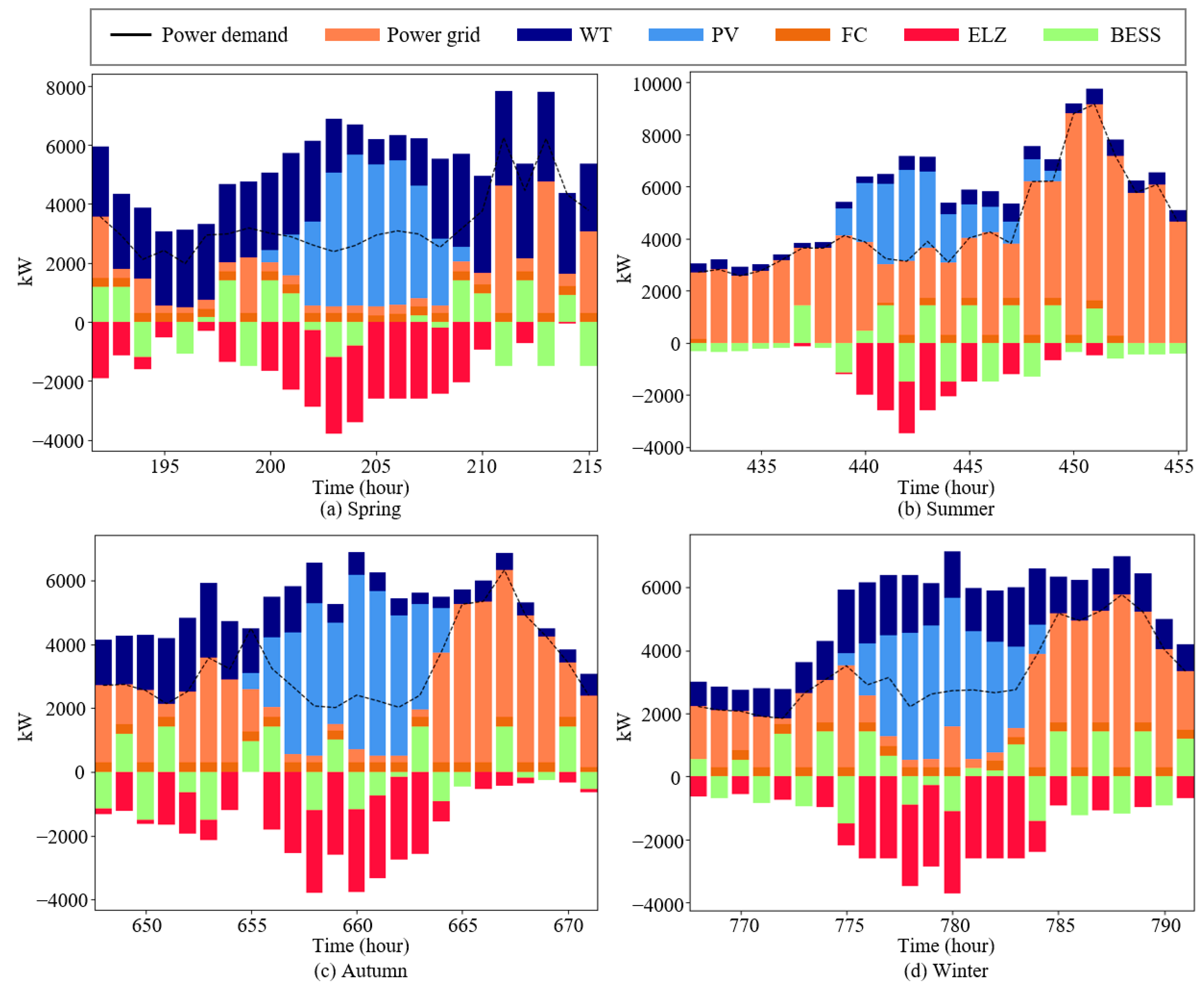
Figure 6.
As shown in
Figure 6, during specific times when the RES output is concentrated, the power supplied from the power grid is reduced, and the active operation of the ELZ can be observed. While the BESS cannot charge and discharge simultaneously and thus does not play a primary role in reducing curtailed energy, it assists in preventing the excessive operation of the ELZ through auxiliary actions, helping to reduce the optimal capacity. Consequently, with the simultaneous application of the BESS and the ELZ, the REP can avoid overinvestment in the energy coupling system facilities and efficiently operate the equipment.
Figure 6 also reflects the characteristics of different seasons. In spring and autumn, when the output of the RES is severely concentrated, especially during periods of high PV output, it can be observed that the electricity supplied from the power grid is extremely low compared to that in summer and winter. Therefore, during these times, the BESS operates in charging mode to maintain power balance or may not discharge if not charged by the ELZ. The ELZ mitigates most of the surplus electricity during the times of concentrated RES output, and without the ELZ, operating solely with the BESS would require continuous charging mode during these peak RES output times. This would lead to a rapid increase in the SOC, potentially causing overinvestment due to unnecessary high capacity, hence the operation of the ELZ is crucial.
In summer, while demand is high, the output of the RES is not, so the operation of the ELZ is minimal. Additionally, it can be seen that the BESS operates very flexibly due to the maximum SOC set during other times of the day. In contrast to that in spring, the BESS helps control the extremely high output of the ELZ.
In winter, a similar pattern to spring and autumn can be observed, but with PV output dropping to zero relatively quickly compared to other seasons, the charging and discharging operations of the BESS during the evening hours without sunlight are found to be very stable.
As a result, this paper demonstrates the feasibility of the REP simultaneously operating BESS and P2G technologies when investing in the energy coupling system. The implementation of the energy coupling system can significantly contribute economically by providing a new business structure from the perspective of the REP, especially considering the increasing proportion of RESs in the future. Moreover, from the perspective of power system operators, it is proven to offer substantial policy contributions by achieving self-sufficiency and the stable integration of RES.
5. Conclusions
This paper advocates for the adoption of an energy coupling system to counterbalance the negative repercussions of an escalating share of RESs on the power grid, and to enrich the benefit structure for REPs amid the increasing electricity market volatility. Through simulation, we scrutinize the system’s advantages for REPs and the reduction in curtailed energy as RES integration grows. Our analysis, differentiating each contributing factor, underscores that operating a single energy system persistently incurs detrimental effects on both RES curtailment and economic benefits. In contrast, deploying the energy coupling system yields favorable outcomes for reducing RES curtailment and enhancing benefits, correlating positively with the rising share of RESs.
While the current study integrates BESS and P2G technologies within the energy coupling framework, the existing literature frequently incorporates Electric Heat Pumps (EHP) within an Integrated Energy System. Thus, future endeavors will explore the amalgamation of various additional technologies. Moreover, considering the paper’s approach to hourly scheduling, a more granular analysis, ideally with 15 min intervals or less, would more accurately reflect the energy coupling system’s operational dynamics; future research will develop optimization strategies for real-time functionality.
This investigation initially focuses on REPs as a singular operative entity within the energy coupling system. However, introducing Independent System Operators (ISOs) or facility investors as new participants could transform the system’s objective function into a multi-objective dilemma, necessitating an optimal equilibrium. Consequently, forthcoming research will construct a more intricate energy coupling system structure and strive to fine-tune the balance across diverse objective functions.
Acknowledging the foundational BESS model employed in this study, we anticipate to address the intricate interplay between the SOC and temperature on the BESS’s performance and safety in future research. We plan to investigate advanced modeling approaches, such as the joint estimation of SOC and temperature using ultrasonic reflection waves, enabling the concurrent acquisition of crucial operational data. This enhanced focus is poised to substantially refine the accuracy and safety of the BESS operations, permitting a thorough comprehension of temperature dynamics’ impact on battery efficiency and longevity. With these sophisticated modeling efforts, we aim to establish a more comprehensive and dependable BESS management framework.


