
Two-Way Coupling Simulation of Fluid-Multibody Dynamics for Estimating Power Generation Performance of Point Absorber Wave Energy Converters


Abstract
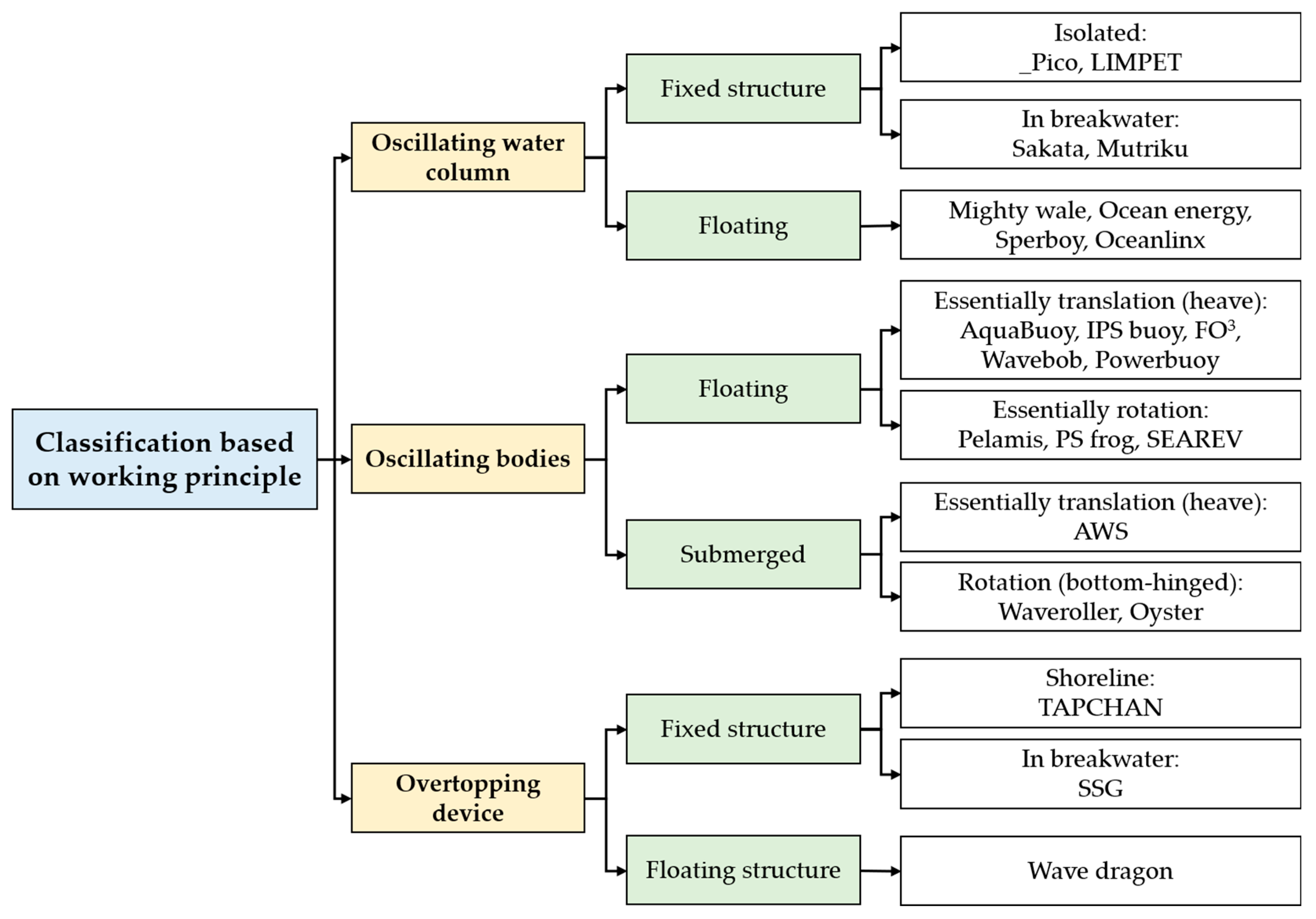
1. Introduction
2. Numerical Method
2.1. Fluid Dynamics (DualSPHysics)
2.1.1. Governing Equations
2.1.2. Discretization in DualSPHysics
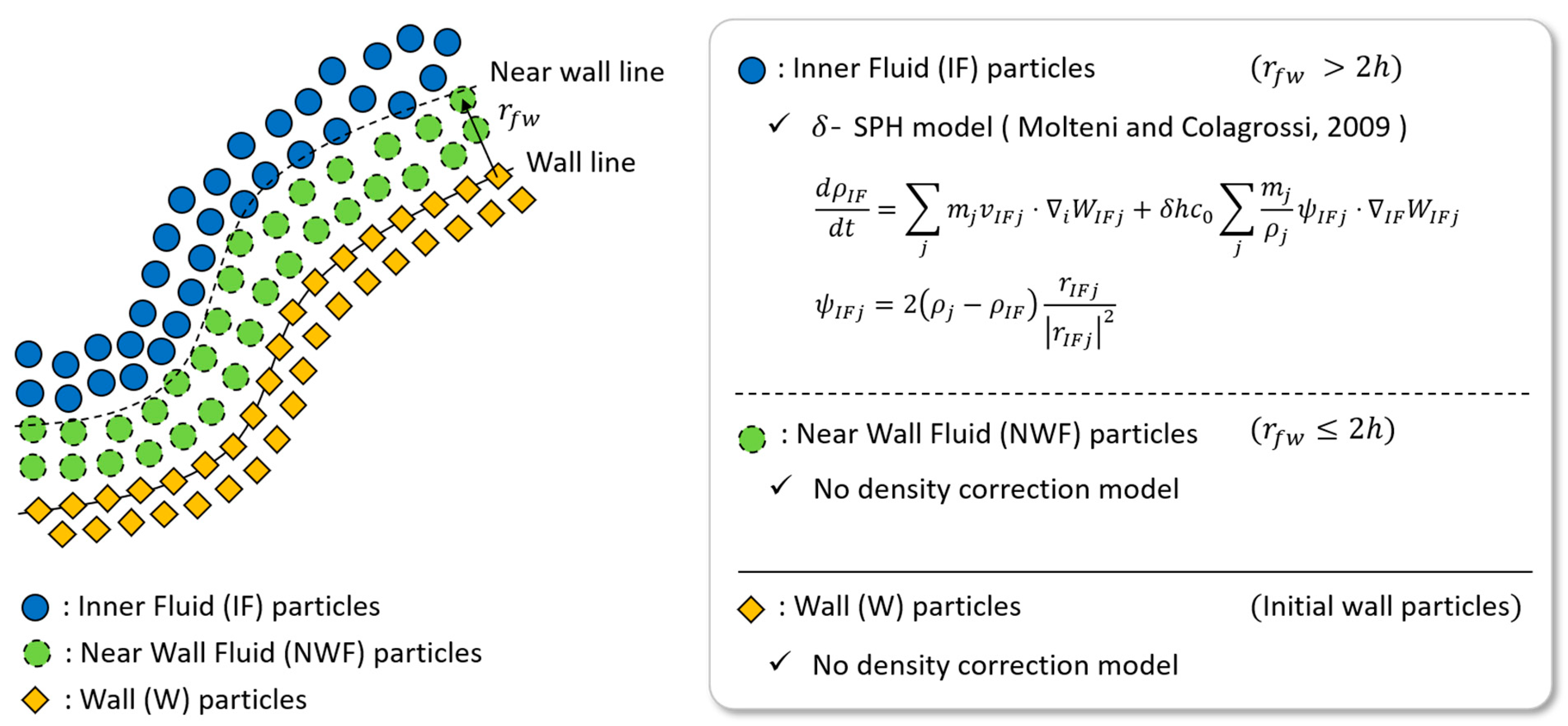
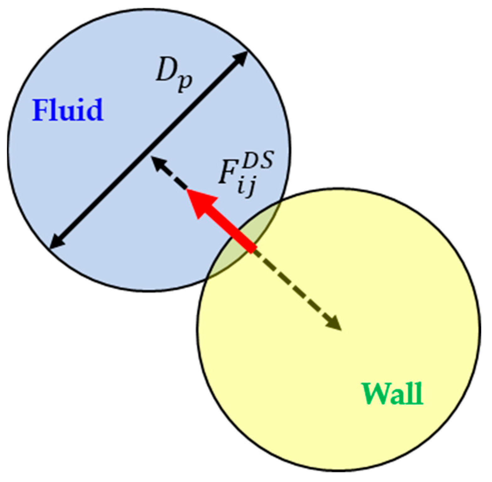
2.1.3. Enhancement of DualSPHysics
2.2. Multibody Dynamics (RecurDyn)
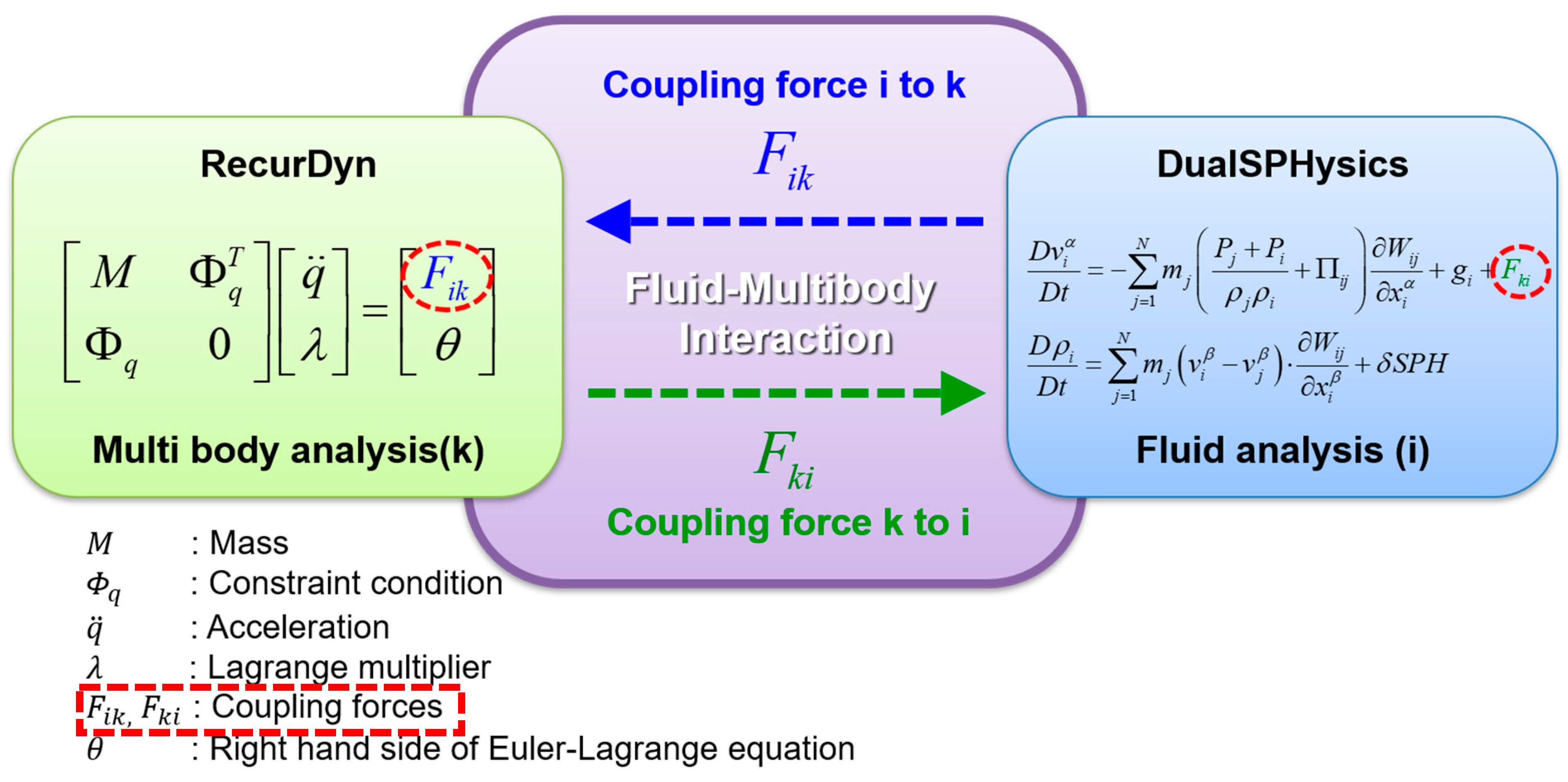
2.3. Two-Way Coupling Simulation between Fluid and Multibody Dynamics
3. Numerical Simulation
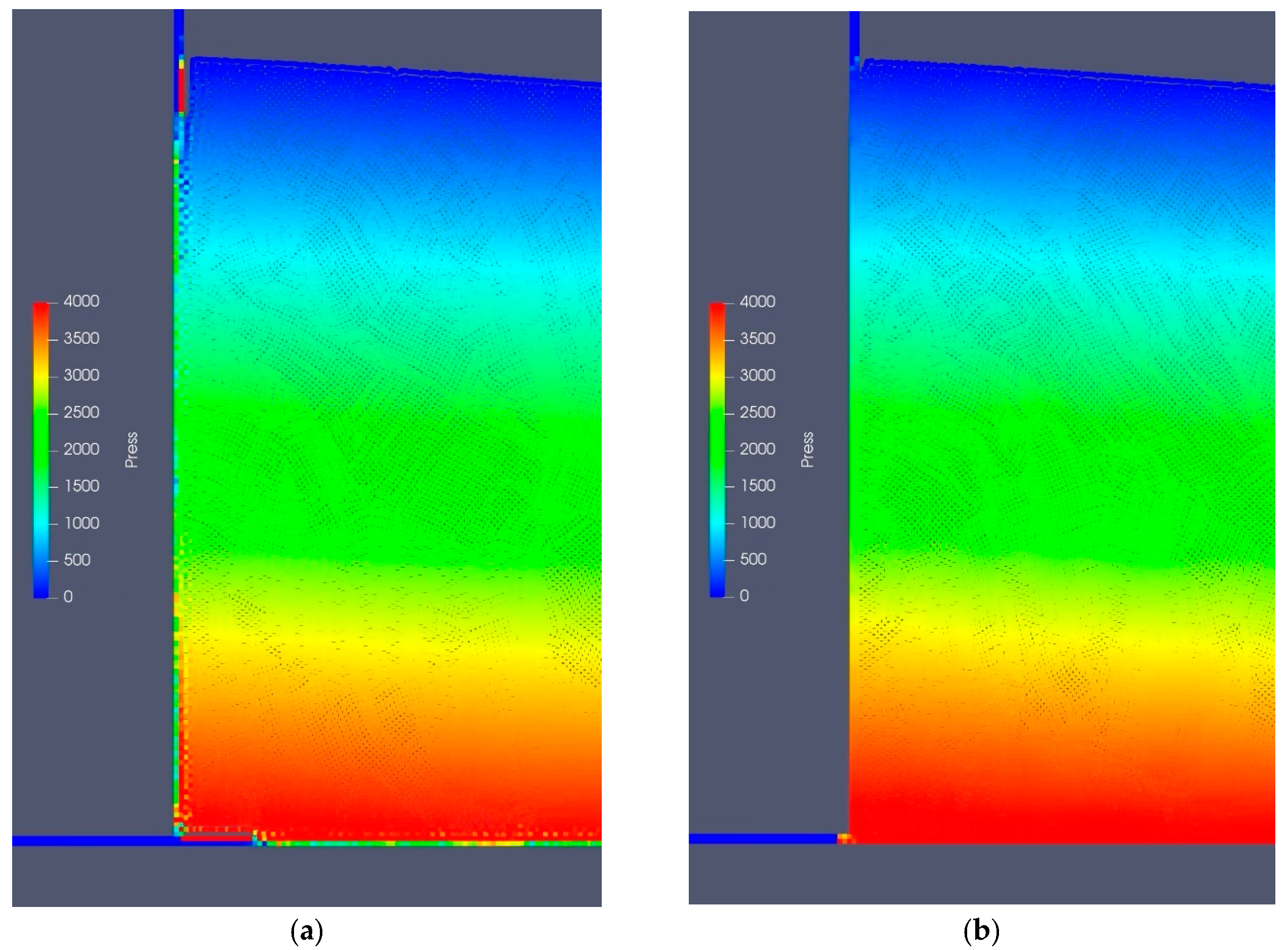
3.1. Verification of Improvement of Flow Analysis Method
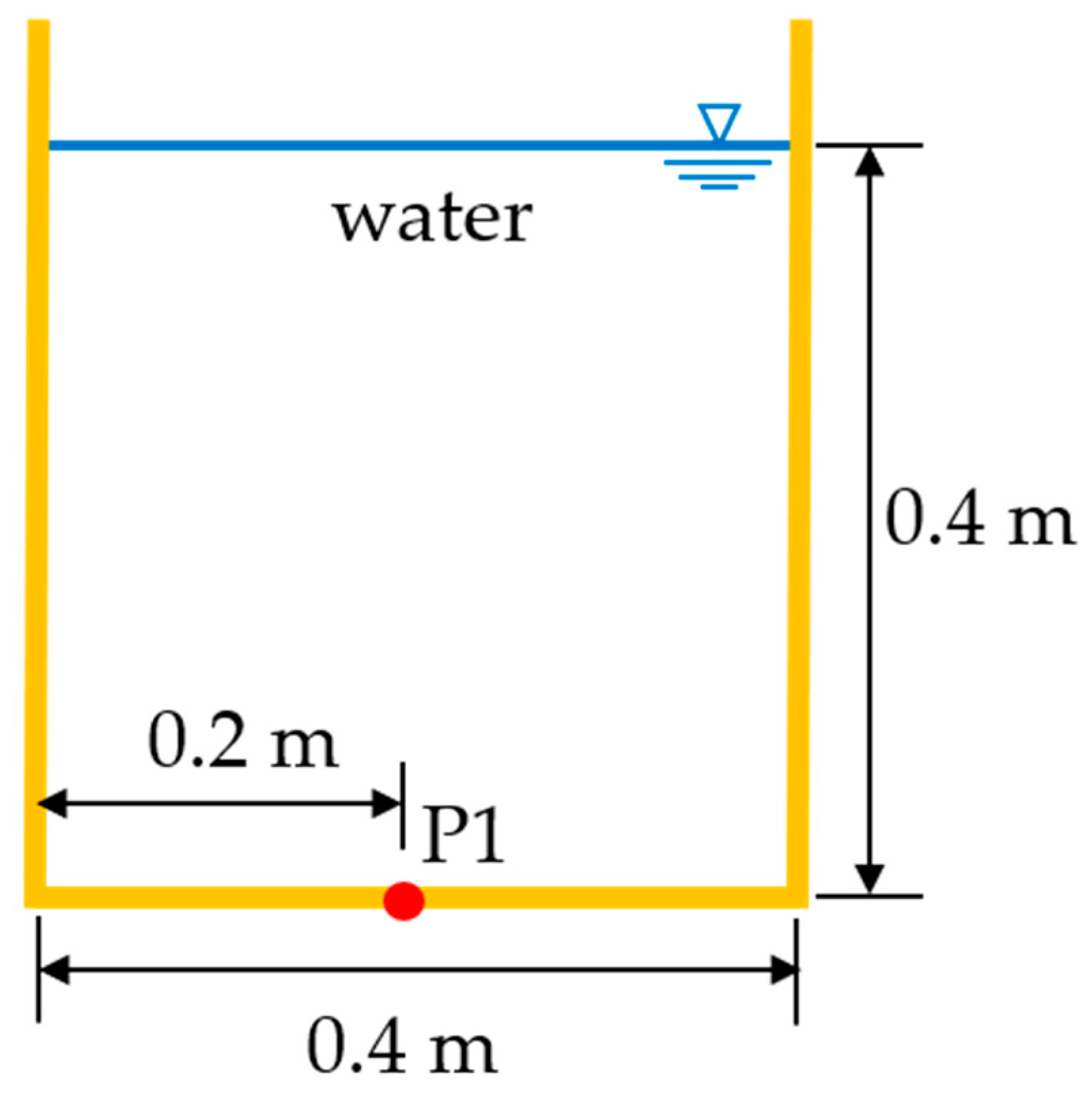
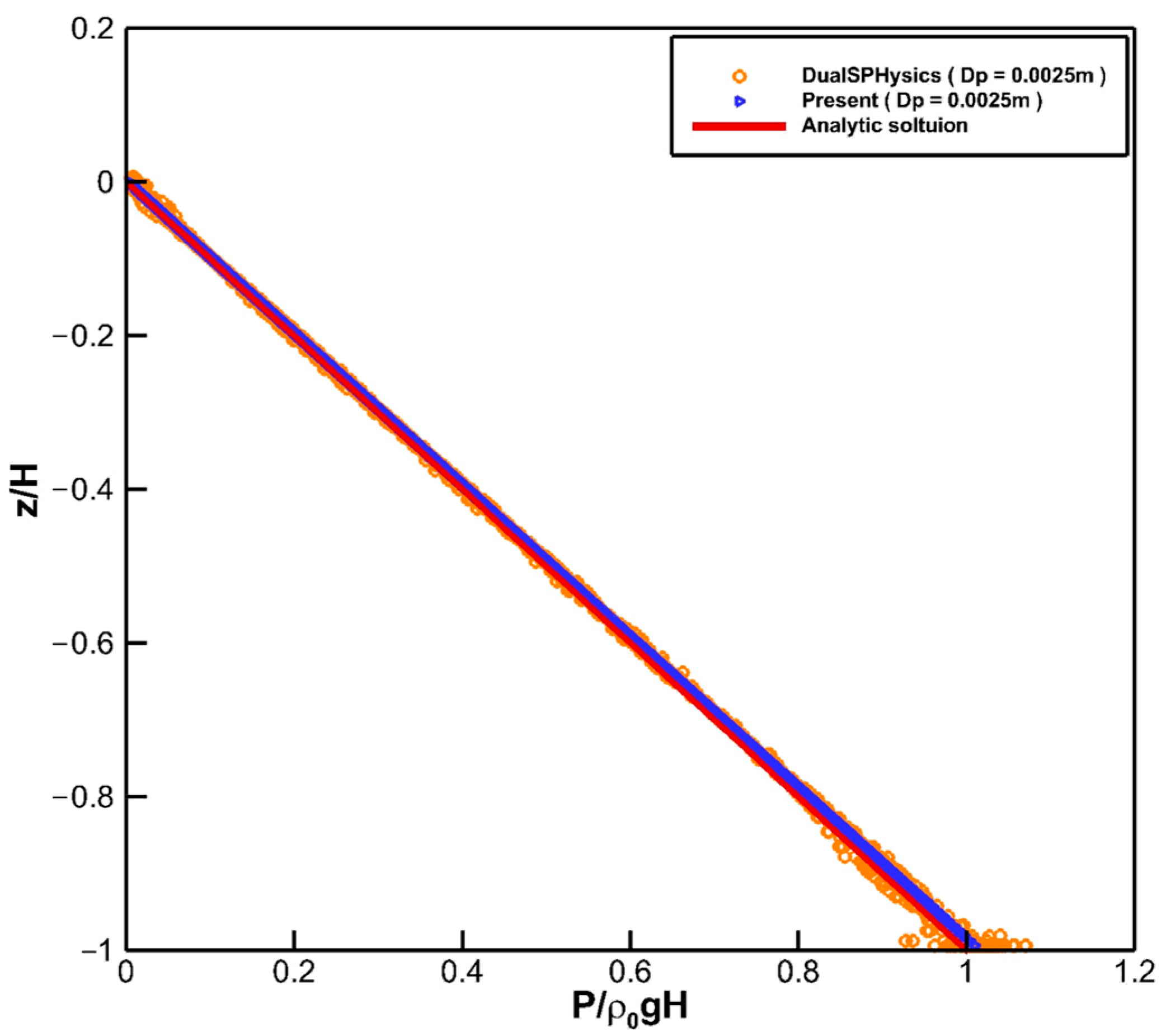
3.1.1. 2D Hydrostatic Problem
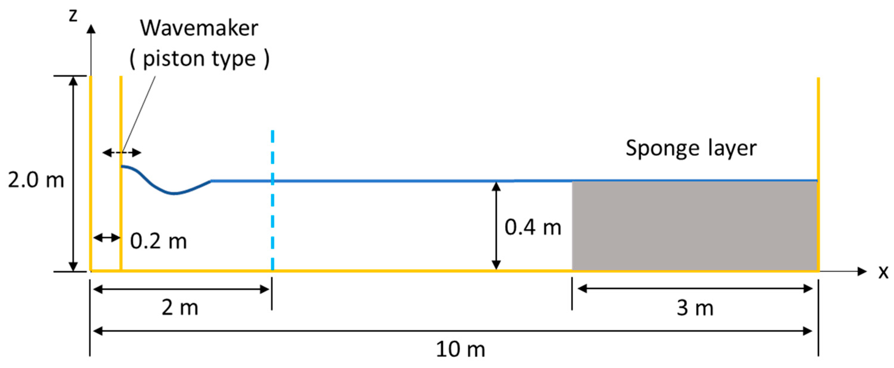
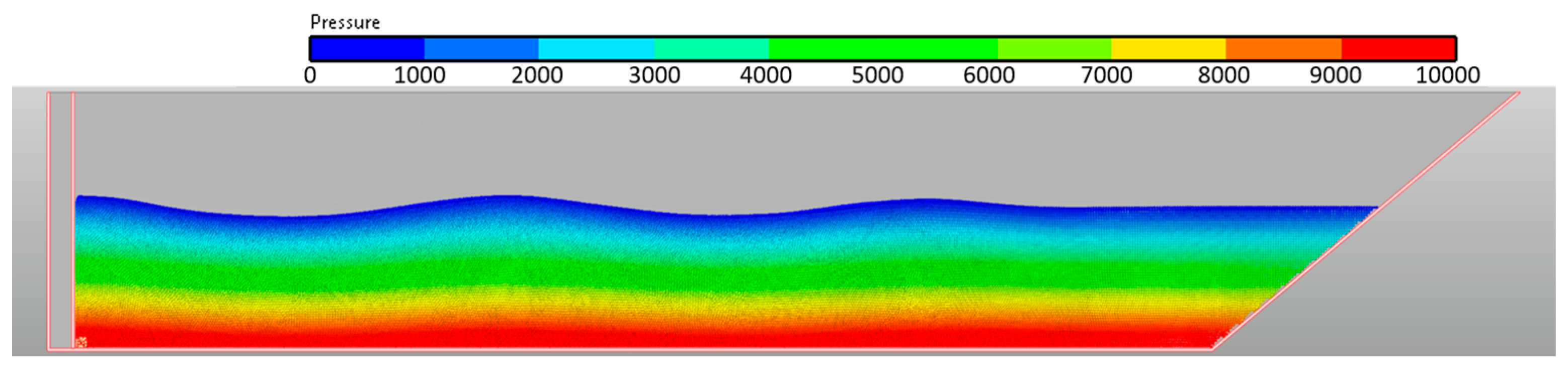
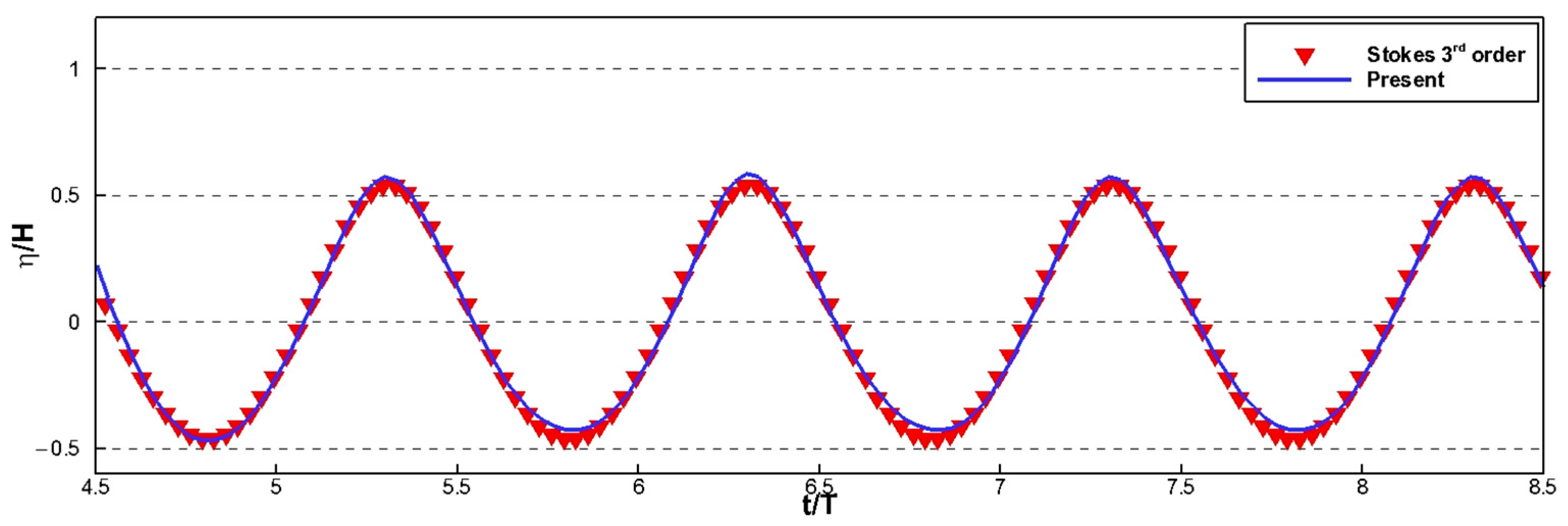
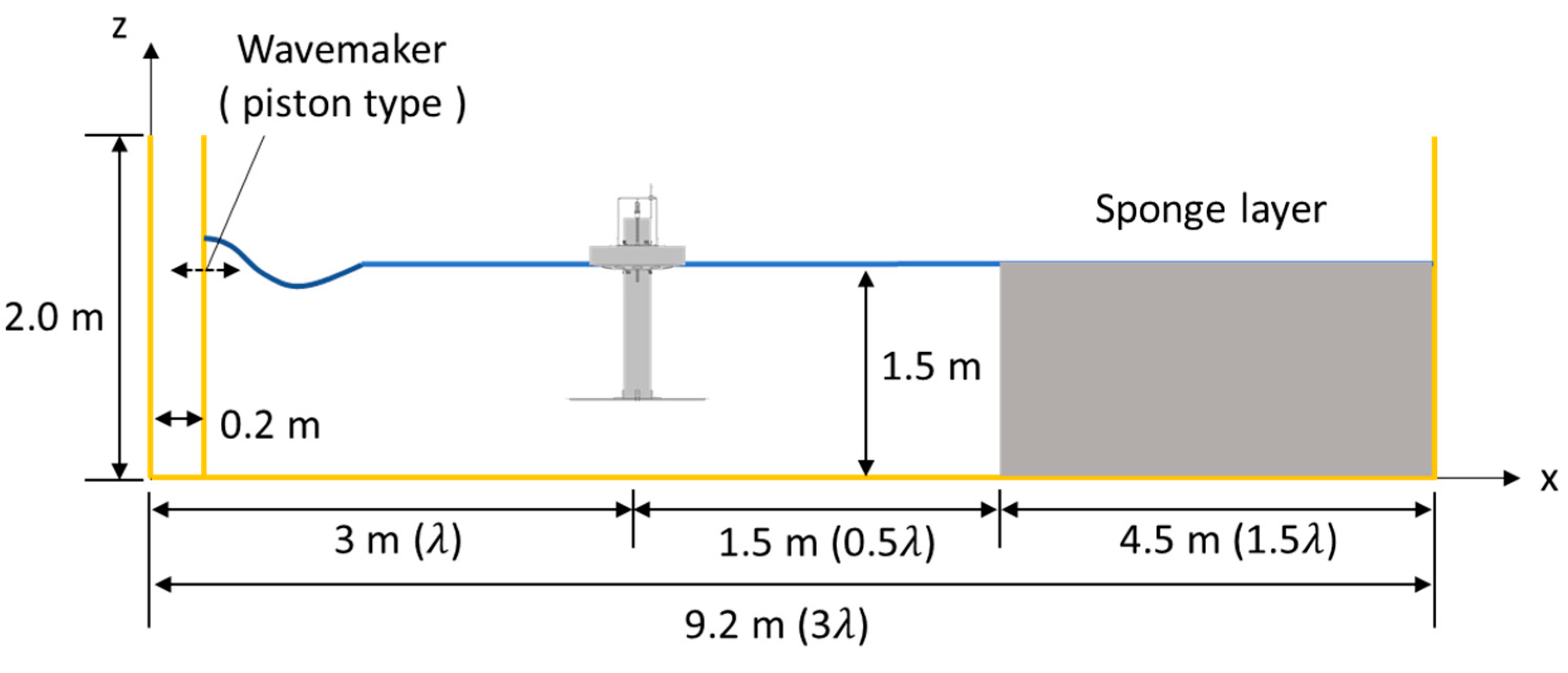
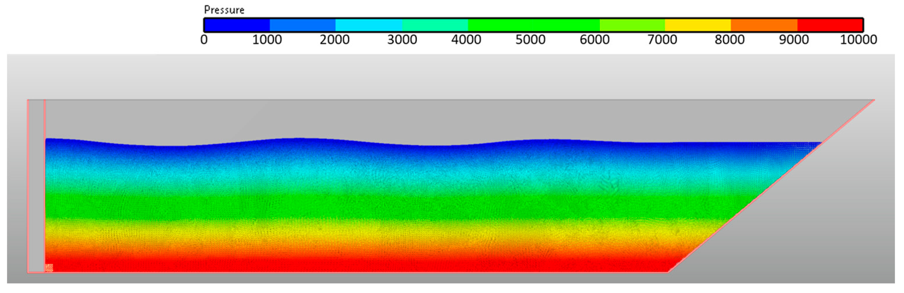
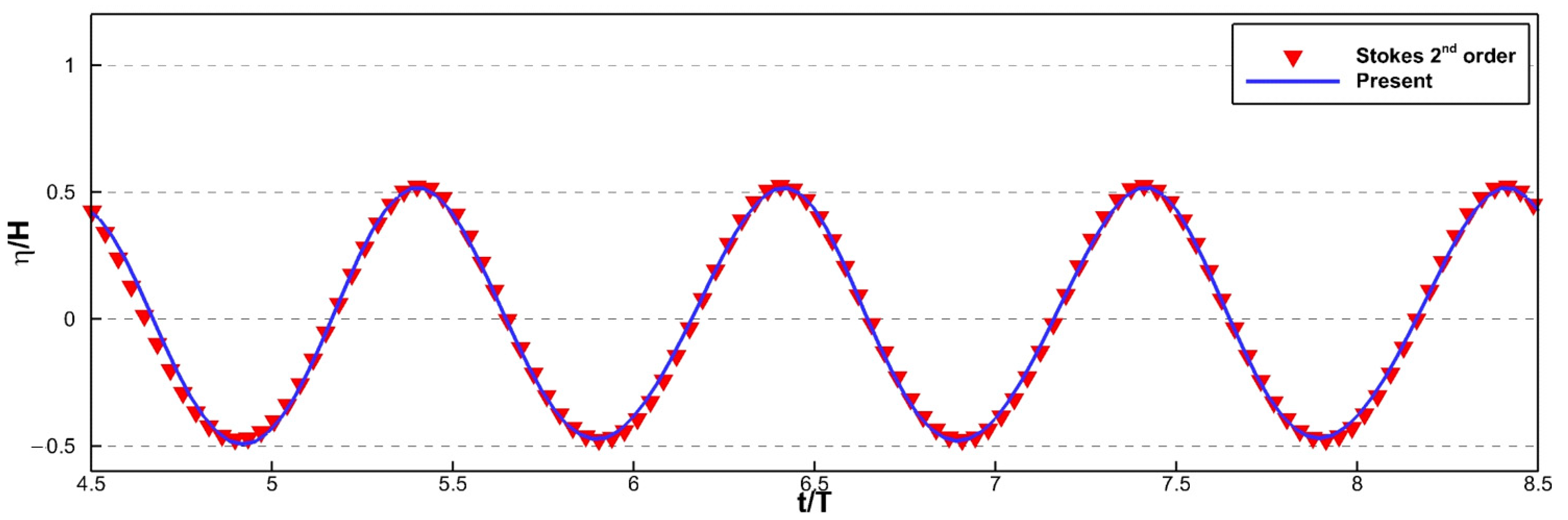
3.1.2. 2D Wave Generation Problem
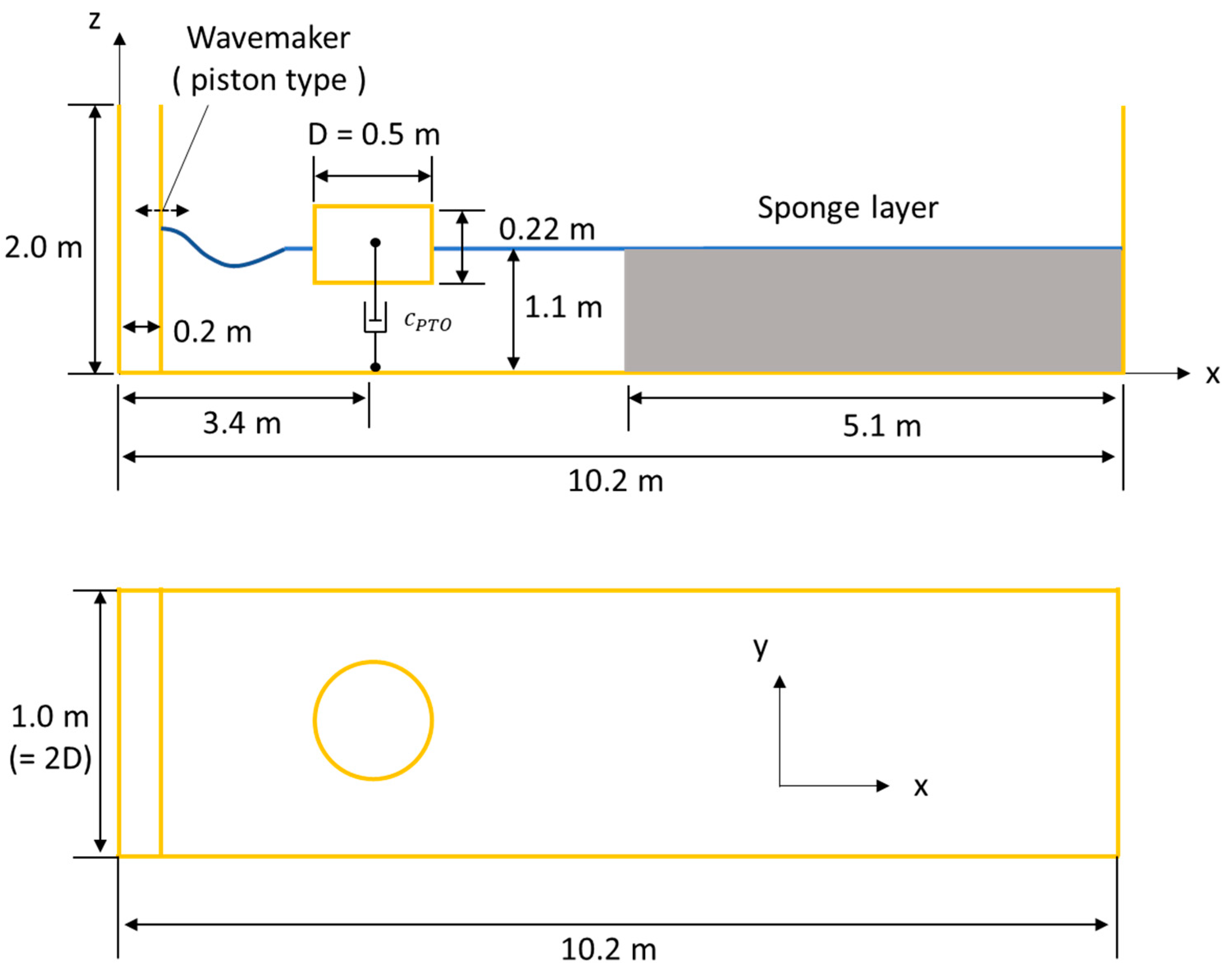
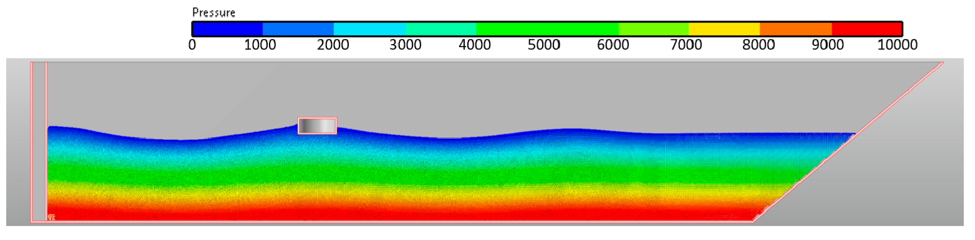
3.2. Verification of Heave Motion of Single-Body Cylinder with PTO under Regular Waves
3.2.1. Definition of Problem and Grid Convergence Tests
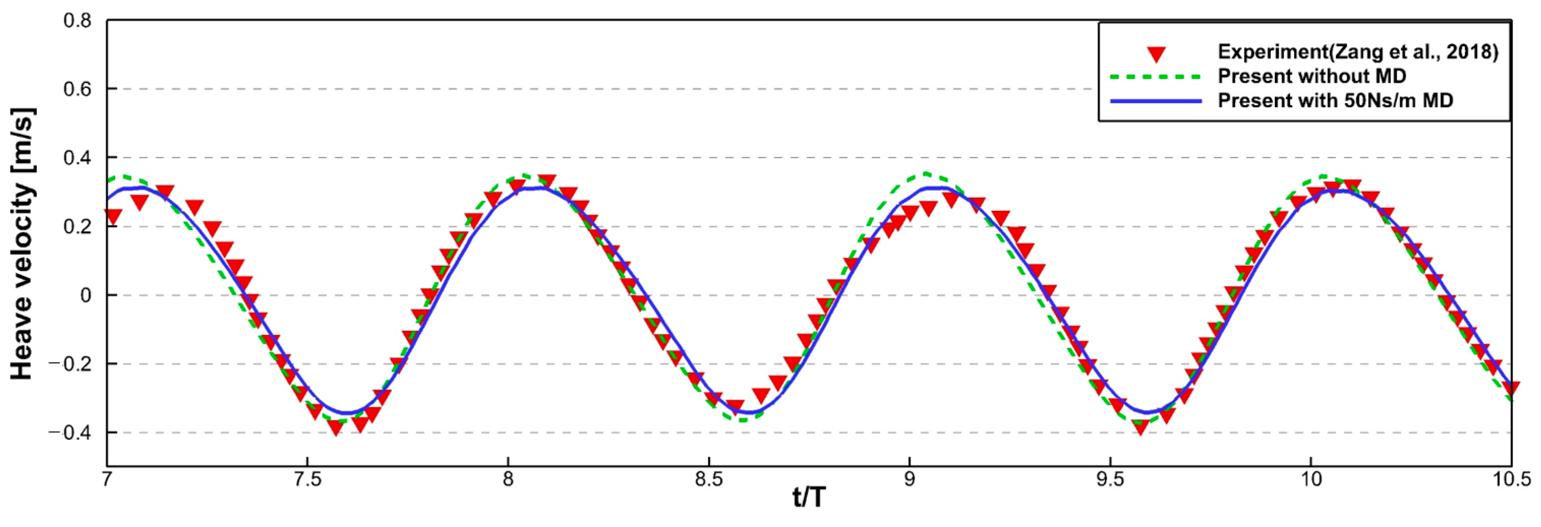
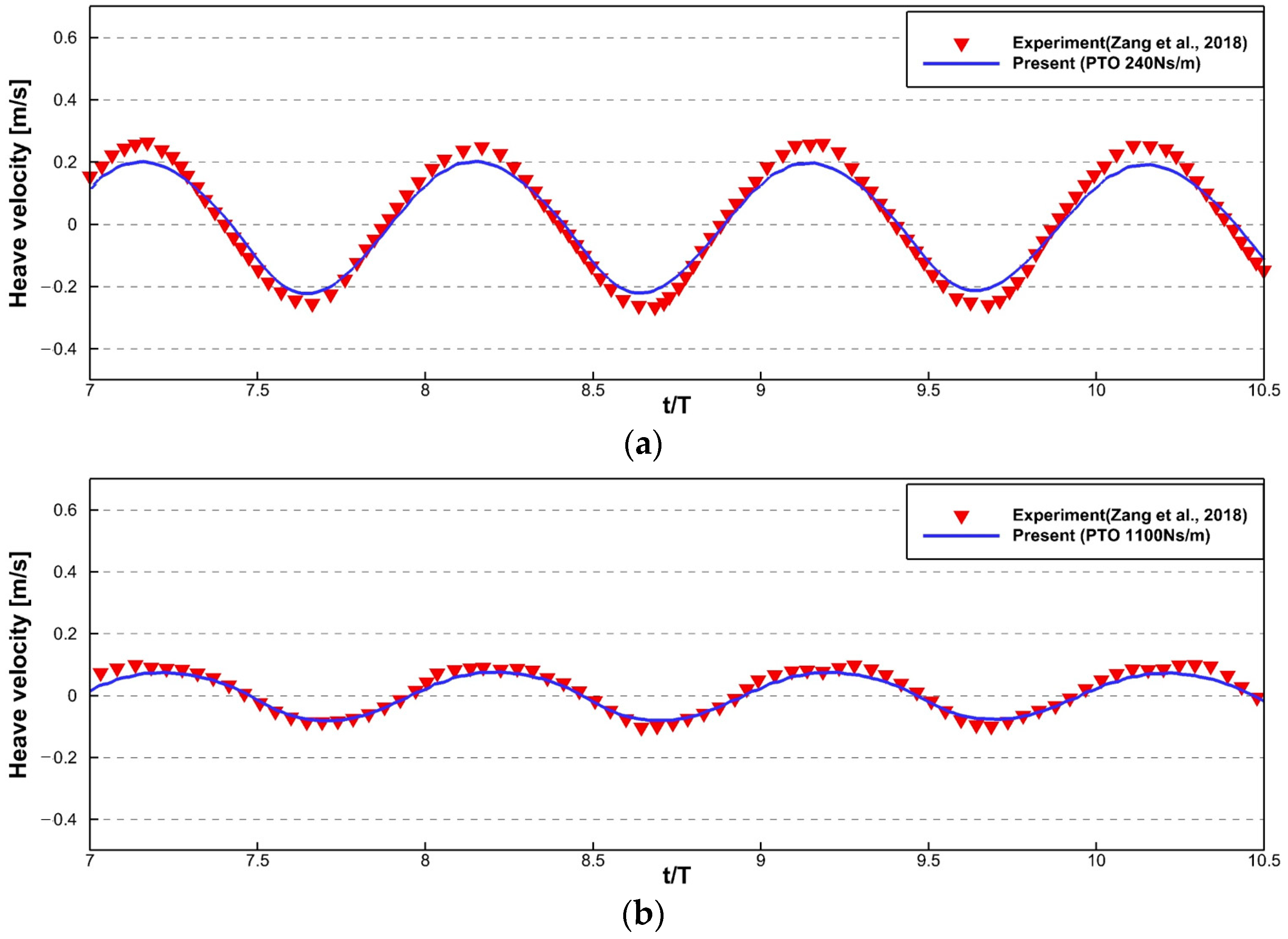
3.2.2. Heave Motion of Single-Body Cylinder with and without PTO in Regular Waves
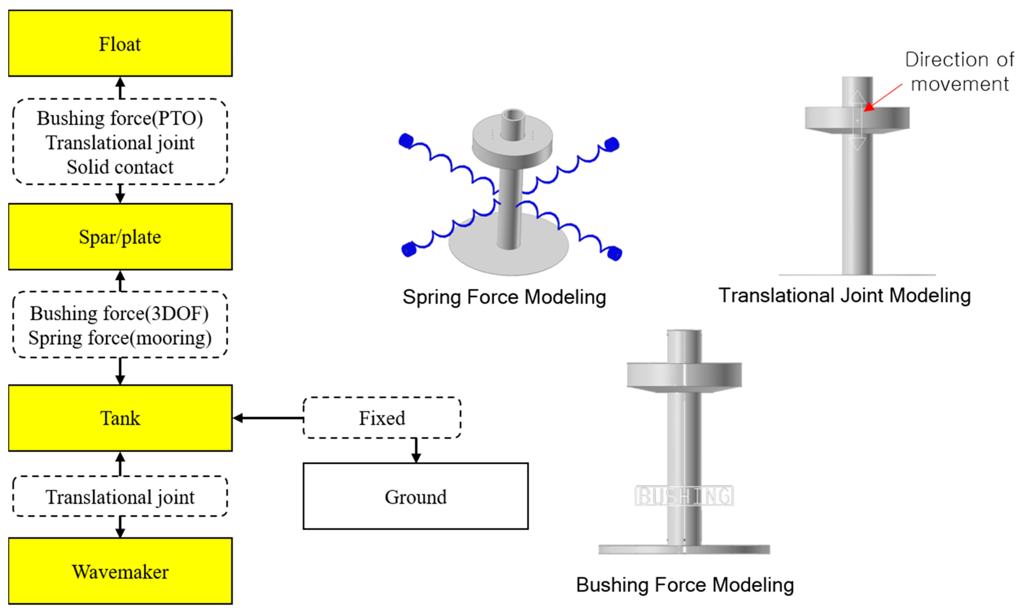
3.3. Verification of 3-DOF Motion of 3D Two-Body WEC with PTO under Regular Waves
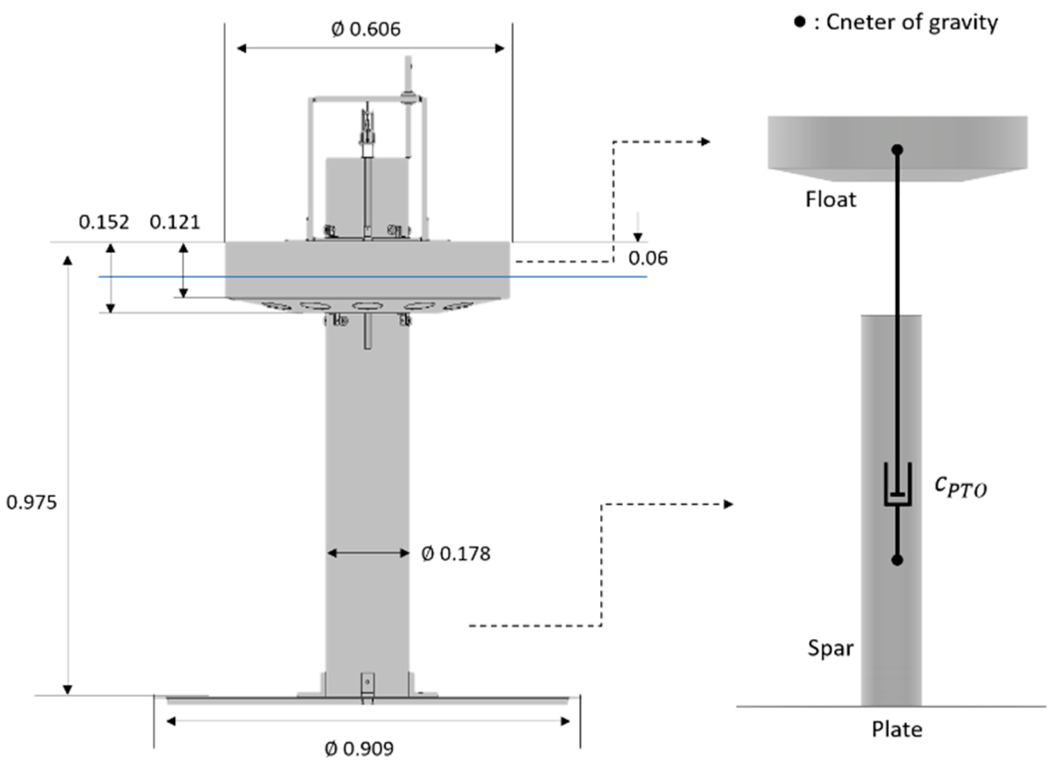
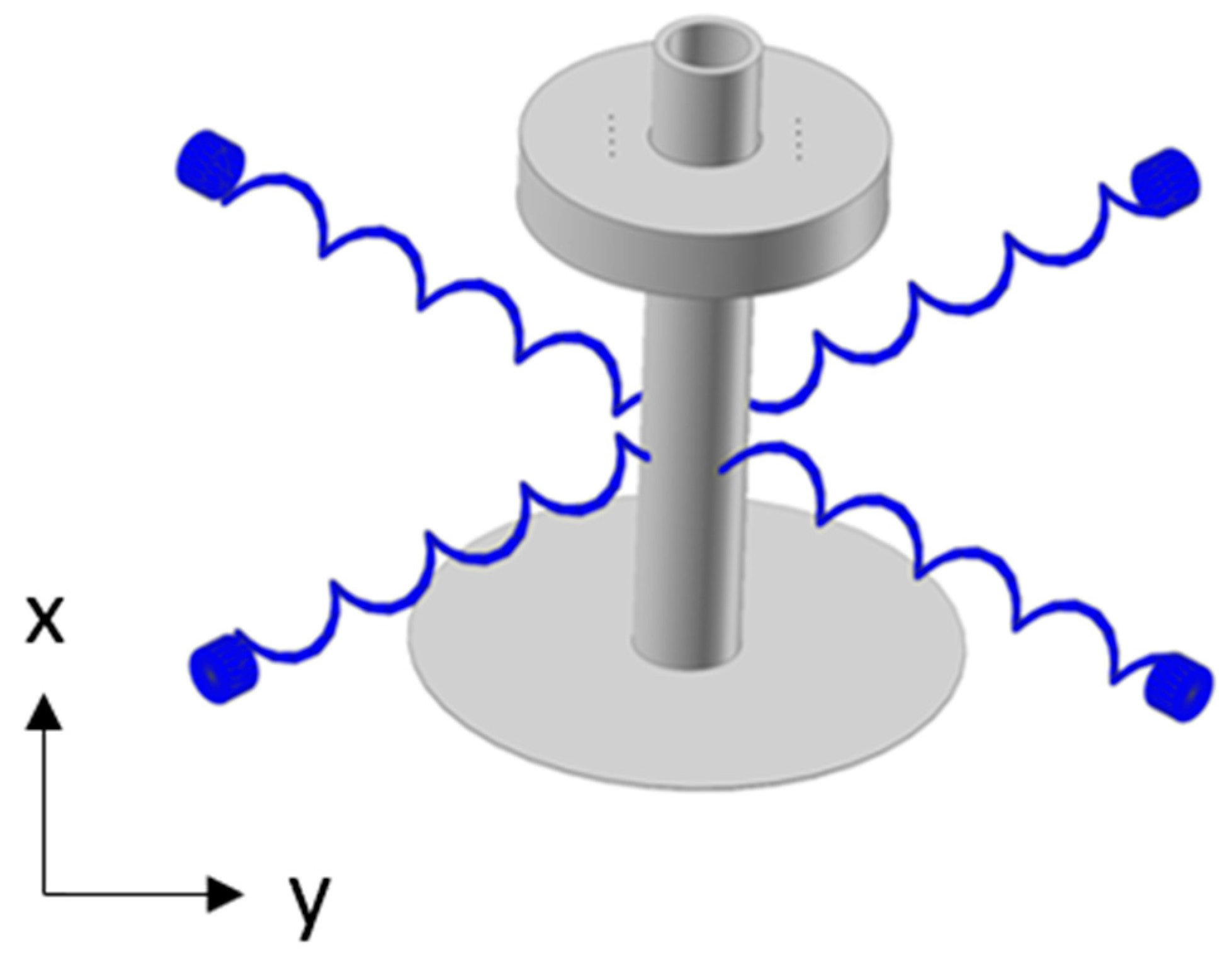
3.3.1. Definition of Problem
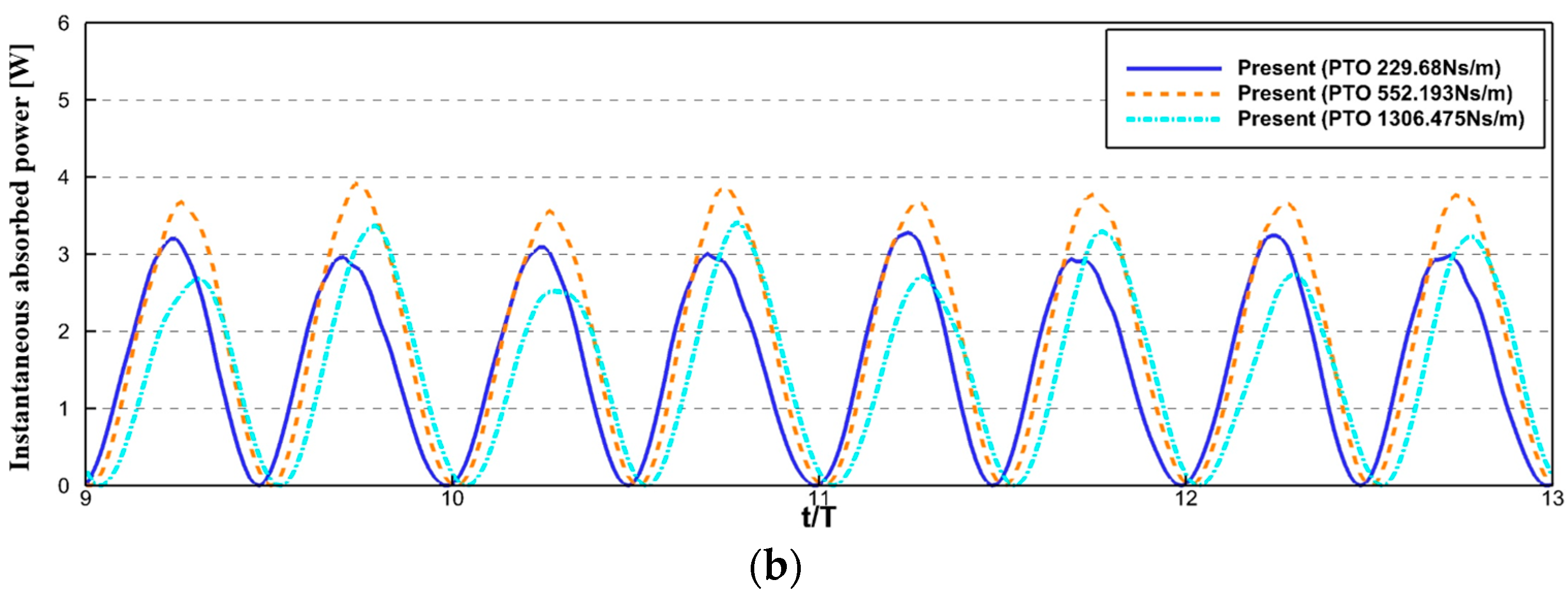
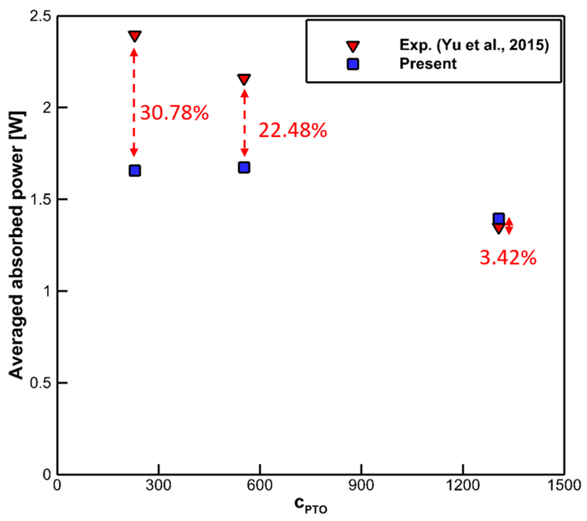
3.3.2. Simulation Results
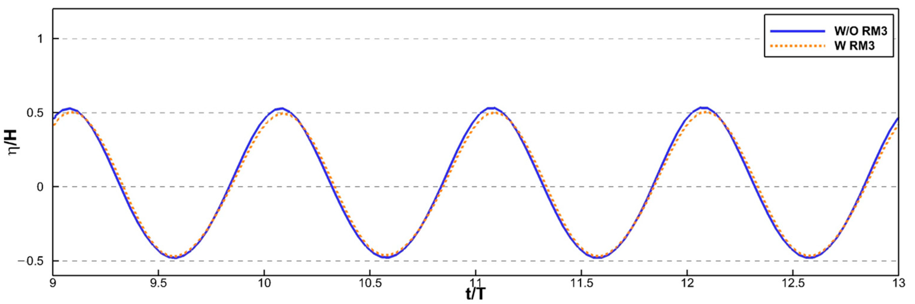
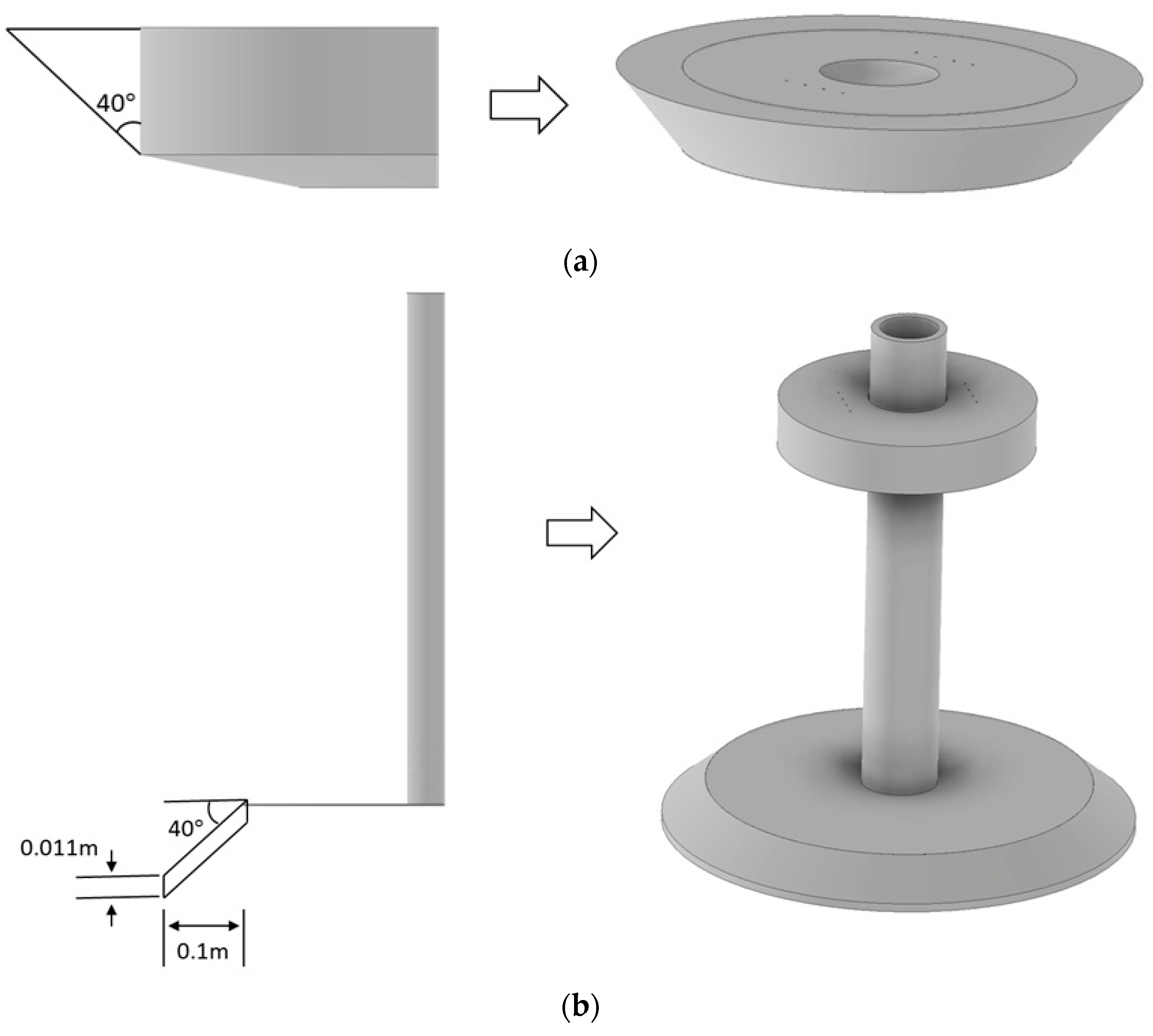
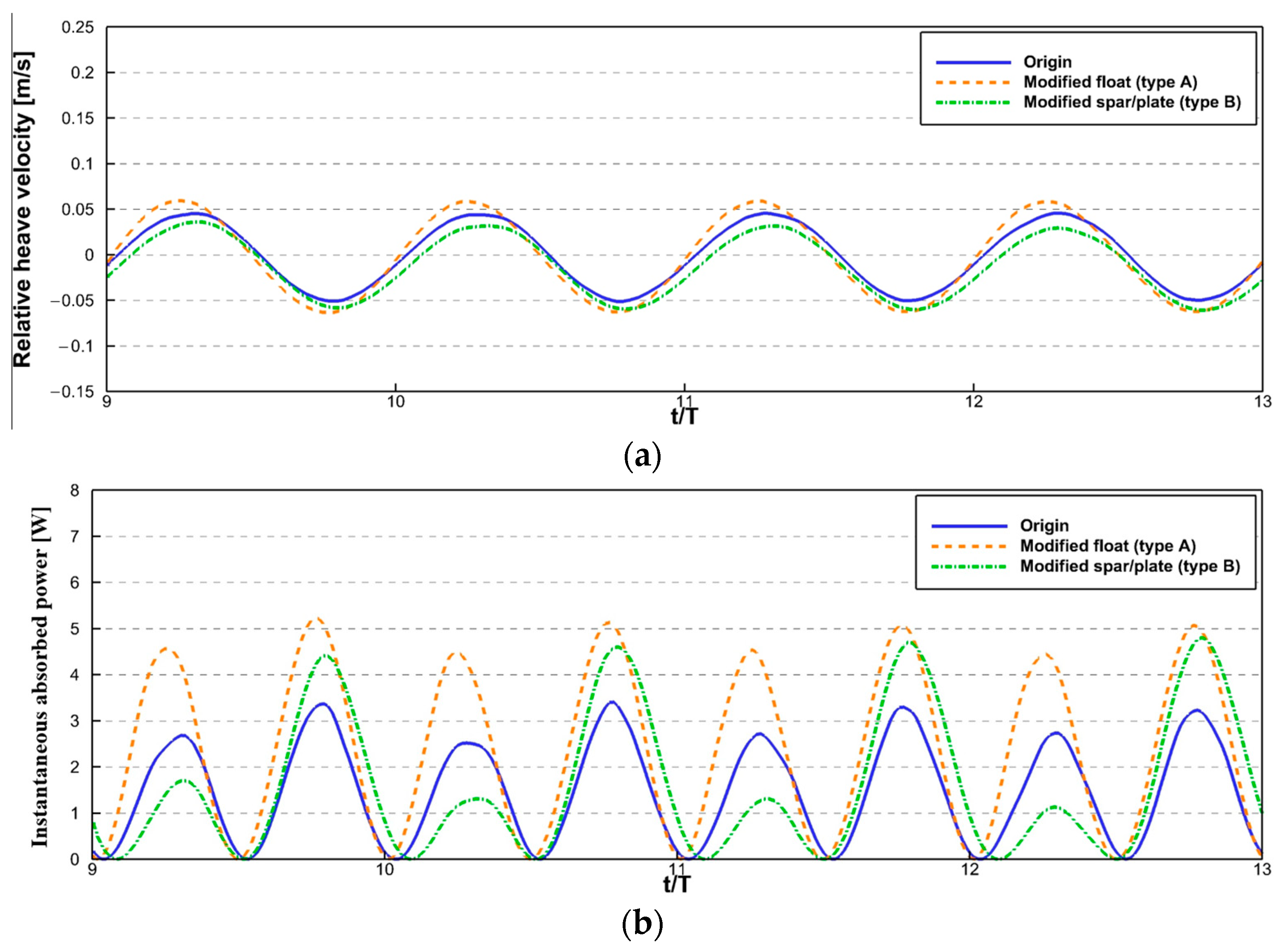
3.4. Application on Shape Change for Improving Power Generation Efficiency of Two-Body WEC
4. Results
5. Discussion
Author Contributions
Funding
Data Availability Statement
Conflicts of Interest
References
- Greenhouse Gas Emissions. Global Greenhouse Gas Emissions Data. Available online: https://www.epa.gov/ghgemissions/global-greenhouse-gas-emissions-data (accessed on 7 July 2021).
- Our World in Data. Available online: https://ourworldindata.org/grapher/modern-renewable-energy-consumption?country=~OWID_WRL (accessed on 7 July 2021).
- Energy Institute. Statistical Review of World Energy. 2023. Available online: https://www.energyinst.org/statistical-review (accessed on 8 February 2023).
- Salter, S. Wave power. Nature 1974, 249, 720–724. [Google Scholar] [CrossRef]
- Li, G.; Weiss, G.; Mueller, M.; Townley, S.; Belmont, M.R. Wave energy converter control by wave prediction and dynamic programming. Renew. Energy 2012, 48, 392–403. [Google Scholar] [CrossRef]
- Alves, I.F. Hydrodynamical Analysis of Bottom-Hinged Oscillating Wave Surge Converters. Master’s Thesis, Tecnico Lisboa, Lisbon, Portugal, July 2016. [Google Scholar]
- Abdelkhalik, O.; Zou, S.; Robinett, R.; Bacelli, G.; Wilson, D.; Coe, R. Control of three degrees-of-freedom wave energy converters using pseudo-spectral methods. J. Dyn. Syst. Meas. Control 2018, 140, 074501. [Google Scholar] [CrossRef]
- Haider, A.S.; Brekken, T.K.; McCall, A. Real-time nonlinear model predictive controller for multiple degrees of freedom wave energy converters with non-ideal power take-off. J. Mar. Sci. Eng. 2021, 9, 890. [Google Scholar] [CrossRef]
- Kim, S.J.; Koo, W.C.; Min, E.H.; Jang, H.; Youn, D.; Lee, B. Experimental study on hydrodynamic performance and wave power takeoff for heaving wave energy converter. J. Ocean Eng. Technol. 2016, 30, 361–366. [Google Scholar] [CrossRef]
- Kim, K.H.; Lee, K.; Sohn, J.M.; Park, S.; Choi, J.S.; Hong, K. Conceptual design of large semi-submersible platform for wave-offshore wind hybrid power generation. J. Korean Soc. Mar. Environ. 2015, 18, 223–232. [Google Scholar] [CrossRef]
- Lee, H.; Poguluri, S.K.; Bae, Y.H. Performance analysis of multiple wave energy converters placed on a floating platform in the frequency domain. Energies 2018, 11, 406. [Google Scholar] [CrossRef]
- Poguluri, S.K.; Kim, D.; Ko, H.S.; Bae, Y.H. Performance analysis of multiple wave energy converters due to rotor spacing. J. Ocean Eng. Technol. 2021, 35, 229–237. [Google Scholar] [CrossRef]
- Jeong, H.J.; Koo, W.C.; Kim, S.J. Numerical study on wave run-up of a circular cylinder with various diffraction parameters and body drafts. J. Ocean Eng. Technol. 2020, 34, 245–252. [Google Scholar] [CrossRef]
- Bozzi, S.; Miquel, A.M.; Antonini, A.; Passoni, G.; Archetti, R. Modeling of point absorber for energy conversion in Italian seas. Energies 2013, 6, 3033–3051. [Google Scholar] [CrossRef]
- Babarit, A.; Hals, J.; Muliawan, M.J.; Kurniawan, A.; Moan, T.; Krokstad, J. Numerical benchmarking study of a selection of wave energy converters. Renew. Energy 2012, 41, 44–63. [Google Scholar] [CrossRef]
- Pastor, J.; Liu, Y. Frequency and time domain modeling and power output for a heaving point absorber wave energy converter. Int. J. Energy Environ. Eng. 2014, 5, 101. [Google Scholar] [CrossRef]
- Li, Y.; Yu, Y.H. A synthesis of numerical methods for modeling wave energy converter-point absorbers. Renew. Sustain. Energy Rev. 2012, 16, 4352–4364. [Google Scholar] [CrossRef]
- Gao, J.L.; He, Z.W.; Huang, X.H.; Liu, Q.; Zang, J.; Wang, G. Effects of free heave motion on wave resonance inside a narrow gap between two boxes under wave actions. Ocean Eng. 2021, 224, 108753. [Google Scholar] [CrossRef]
- Gao, J.L.; Lyu, J.; Wang, J.H.; Zhang, J.; Liu, Q.; Zang, J.; Zou, T. Study on transient gap resonance with consideration of the motion of floating body. China Ocean Eng. 2022, 36, 994–1006. [Google Scholar] [CrossRef]
- Gong, S.K.; Gao, J.L.; Mao, H.F. Investigations on fluid resonance within a narrow gap formed by two fixed bodies with varying breadth ratios. China Ocean Eng. 2023, 37, 962–974. [Google Scholar] [CrossRef]
- Yeylaghi, S.; Moa, B.; Oshkai, P.; Buckham, B.; Crawford, C. ISPH modelling of an oscillating wave surge converter using an OpenMP-based parallel approach. J. Ocean Eng. Mar. Energy 2016, 2, 301–312. [Google Scholar] [CrossRef]
- Hirt, C.W.; Nichols, B.D. Volume of fluid (VOF) method for the dynamics of free boundaries. J. Comput. Phys. 1981, 39, 201–225. [Google Scholar] [CrossRef]
- Sussman, M.; Smereka, P.; Osher, S. A level set approach for computing solutions to incompressible two-phase flow. J. Comput. Phys. 1994, 114, 146–159. [Google Scholar] [CrossRef]
- Brito, M.; Canelas, R.B.; Garcia-Feal, O.; Dominguez, J.M.; Crespo, A.J.C.; Ferreira, R.M.L.; Neves, M.G.; Teixeira, L. A numerical tool for modelllng oscillating wave surge converter with nonlinear mechanical constraints. Renew. Energy 2020, 146, 2024–2043. [Google Scholar] [CrossRef]
- Yeylaghi, S.; Moa, B.; Beatty, S.; Buckham, B.; Oshkai, P.; Crawford, C. SPH modeling of hydrodynamic loads on a point absorber wave energy converter hull. In Proceedings of the 11th European Wave and Tidal Energy Conference, Nantes, France, 6–11 September 2015. [Google Scholar]
- Zhang, D.H.; Shi, Y.X.; Huang, C.; Si, Y.L.; Huang, B.; Li, W. SPH method with applications of oscillating wave surge converter. Ocean Eng. 2018, 156, 273–285. [Google Scholar] [CrossRef]
- Monaghan, J.J. An introduction to SPH. Comput. Phys. Commun. 1988, 48, 89–96. [Google Scholar] [CrossRef]
- Koshizuka, S.; Oka, Y. Moving-particle semi-implicit method for fragmentation of incompressible fluid. Nucl. Sci. Eng. 1996, 123, 421–434. [Google Scholar] [CrossRef]
- Crespo, A.J.C.; Dominguez, J.M.; Rogers, B.D.; Gomez-Gesteira, M.; Longshaw, S.; Canelas, R.; Vacondia, R.; Barreiro, A.; Garcia-Feal, O. DualSPHysics: Open-source parallel CFD solver based on smoothed particle hydrodynamics (SPH). Comput. Phys. Commun. 2015, 184, 204–216. [Google Scholar] [CrossRef]
- Molteni, D.; Colagrossi, A. A simple procedure to improve the pressure evaluation in hydrodynamic context using the SPH. Comput. Phys. Commun. 2009, 180, 861–872. [Google Scholar] [CrossRef]
- Antuono, M.; Colagrossi, A.; Marrone, S.; Molteni, D. Free-surface flows solved by means of sph schemes with numerical diffusive terms. Comput. Phys. Commun. 2010, 181, 532–549. [Google Scholar] [CrossRef]
- Shepard, D. A two-dimensional interpolation function for irregularly-spaced data. In Proceedings of the 1968 ACM National Conference, New York, NY, USA, 27–29 August 1968. [Google Scholar]
- Dalrymple, R.A.; Rogers, B.D. Numerical modeling of water waves with the SPH method. Coast. Eng. 2006, 53, 141–147. [Google Scholar] [CrossRef]
- Ren, B.; He, M.; Dong, P.; Wen, H. Nonlinear simulations of wave-induced motions of a freely floating body using WCSPH method. Appl. Ocean Res. 2015, 50, 1–12. [Google Scholar] [CrossRef]
- Yun, S.M.; Kim, S.P.; Chung, S.M.; Shin, W.J.; Cho, D.S.; Park, J.C. Structural safety assessment of connection between sloshing tank and 6-DOF platform using co-simulation of fluid and multi-flexible-body dynamics. Water 2020, 12, 2108. [Google Scholar] [CrossRef]
- FunctionBay. RecurDyn Manual, Version V9R3; FunctionBay: Seongnam, Republic of Korea, 2021. [Google Scholar]
- Zang, Z.; Zhang, Q.; Qi, Y.; Fu, X. Hydrodynamic responses and efficiency analyses of a heaving-buoy wave energy converter with PTO damping in regular and irregular waves. Renew. Energy 2018, 116, 527–542. [Google Scholar] [CrossRef]
- Yu, Y.H.; Lawson, M.; Li, Y.; Previsic, M.; Epler, J.; Lou, J. Experimental Wave Tank Test for Reference Model 3 Floating-Point Absorber Wave Energy Converter Project; National Renewable Energy Laboratory: Golden, CO, USA, 2015.
- Monaghan, J.J. Smoothed particle hydrodynamics. Annu. Rev. Astron. Astrophys. 1992, 30, 543–574. [Google Scholar] [CrossRef]
- Wendland, H. Piecewise polynomial, positive definite and compactly supported radial functions of minimal degree. Adv. Comput. Math. 1995, 4, 389–396. [Google Scholar] [CrossRef]
- Tsuruta, N.; Khayyer, A.; Gotoh, H. A short note on dynamic stabilization of moving particle semi-implicit method. Comput. Fluids 2013, 82, 158–164. [Google Scholar] [CrossRef]
- FunctionBay. Theoretical_Manual, Version V9R3; FunctionBay: Seongnam, Republic of Korea, 2021. [Google Scholar]
- Crespo, A.J.C.; Gomez-Gesteira, M.; Dalymple, R.A. Boundary conditions generated by dynamic particles in SPH methods. CMC-Comput. Mater. Contin. 2007, 5, 173–184. [Google Scholar]
- Roache, P.J. Perspective: A method for uniform reporting of grid refinement studies. J. Fluids Eng. 1994, 166, 405–413. [Google Scholar] [CrossRef]
- Misume, N.; Yoshimura, S.; Murotani, K.; Yamada, T. Explicitly represented polygon wall boundary model for the explicit MPS method. Comput. Part. Mech. 2015, 2, 73–89. [Google Scholar] [CrossRef]
- Zhang, T.; Koshizuka, S.; Murotani, K.; Shibata, K.; Ishii, E. Improvment of pressure distribution to arbitrary geometry with boundary condition represented by polygons in particle method. Int. J. Numer. Methods Eng. 2017, 112, 685–710. [Google Scholar] [CrossRef]
- Altomare, C.; Dominguez, J.M.; Crespo, A.J.C.; Gonzalez-Cao, J.; Suzuki, T.; Gomez-Gesteira, M.; Troch, P. Long-crested wave generation and absorption for SPH-based DualSPHysis model. Coast. Eng. 2017, 127, 37–54. [Google Scholar] [CrossRef]
- Berenjkoob, M.N.; Ghiasi, M.; Soares, C.G. Influence of the shape of a buoy on the efficiency of its dual-motion wave energy conversion. Energy 2021, 214, 118998. [Google Scholar] [CrossRef]
- Liu, Z.; Frigaard, P. Generation and Analysis of Random Waves; Aalborg Universitet: Aalborg, Denmark, 1999; pp. 39–79. [Google Scholar]


| Parameter | Value | |||
|---|---|---|---|---|
| Particle size (m) | 0.02 | 0.01 | 0.005 | 0.0025 |
| Time integration | Symplectic scheme | |||
| SPH Kernel | Wendland | |||
| Density diffusion | Present | |||
| Courant number | 0.1 | |||
| Viscosity model | = 0.01) | |||
| ) | 1000 | |||
| Parameter | Value | ||
|---|---|---|---|
| Particle size (m) | 0.08 | 0.04 | 0.02 |
| Time integration | Symplectic scheme | ||
| SPH Kernel | Wendland | ||
| Density diffusion | Present | ||
| Courant number | 0.1 | ||
| Viscosity model | = 0.01) | ||
| ) | 1000 | ||
| Component | Mass (kg) | Center of Gravity (m) | ) |
|---|---|---|---|
| Float | 20.23 | [0, 0, −0.022] | [0.53, 0.54, 0.95] |
| Spar/plate | 25.4 + 12.3 (modified) | [0, 0, −0.65] | [3.5, 3.5, 0.73] |
| Parameter | Value | ||
|---|---|---|---|
| ) | 229.68 | 552.193 | 1306.475 |
| ) | 0.011 (about 15,580,000 particles) | ||
| H/Dp | 8.3 | ||
| ) | 20 | ||
| Courant number | 0.1 | ||
| Numerical method | Present | ||
| ) | 1000 | ||
Disclaimer/Publisher’s Note: The statements, opinions and data contained in all publications are solely those of the individual author(s) and contributor(s) and not of MDPI and/or the editor(s). MDPI and/or the editor(s) disclaim responsibility for any injury to people or property resulting from any ideas, methods, instructions or products referred to in the content. |
© 2024 by the authors. Licensee MDPI, Basel, Switzerland. This article is an open access article distributed under the terms and conditions of the Creative Commons Attribution (CC BY) license (https://creativecommons.org/licenses/by/4.0/).
Share and Cite
Yun, S.-M.; Shin, H.-S.; Park, J.-C. Two-Way Coupling Simulation of Fluid-Multibody Dynamics for Estimating Power Generation Performance of Point Absorber Wave Energy Converters. Energies 2024, 17, 930. https://doi.org/10.3390/en17040930
Yun S-M, Shin H-S, Park J-C. Two-Way Coupling Simulation of Fluid-Multibody Dynamics for Estimating Power Generation Performance of Point Absorber Wave Energy Converters. Energies. 2024; 17(4):930. https://doi.org/10.3390/en17040930
Chicago/Turabian StyleYun, Sang-Moon, Hee-Sung Shin, and Jong-Chun Park. 2024. "Two-Way Coupling Simulation of Fluid-Multibody Dynamics for Estimating Power Generation Performance of Point Absorber Wave Energy Converters" Energies 17, no. 4: 930. https://doi.org/10.3390/en17040930
APA StyleYun, S.-M., Shin, H.-S., & Park, J.-C. (2024). Two-Way Coupling Simulation of Fluid-Multibody Dynamics for Estimating Power Generation Performance of Point Absorber Wave Energy Converters. Energies, 17(4), 930. https://doi.org/10.3390/en17040930