Article

LCA of Recycled (NdDy)FeB Permanent Magnets through Hydrogen Decrepitation

by
Antonella Accardo
*,
Trentalessandro Costantino
and
Ezio Spessa
*
Department of Energetics, Interdepartmental Center for Automotive Research and Sustainable Mobility—CARS@PoliTO, Politecnico di Torino, Corso Duca degli Abruzzi 24, 10129 Turin, Italy
*
Authors to whom correspondence should be addressed.
Energies 2024, 17(4), 908; https://doi.org/10.3390/en17040908
Submission received: 28 December 2023 / Revised: 7 February 2024 / Accepted: 12 February 2024 / Published: 15 February 2024
(This article belongs to the Special Issue Life Cycle Assessment (LCA) of Renewable Energy Technologies)

Abstract

:
Compared to conventional fossil-fueled vehicles, electric vehicles offer several environmental benefits. However, even electric vehicles are not completely environmentally friendly because many of their parts are not recycled today. These parts, especially the magnets that power them, end up in landfills at the end of the vehicle’s life cycle. This study aims to evaluate the environmental impacts of recycled (NdDy)FeB permanent magnets obtained by means of a novel hydrogen-decrepitation-based, magnet-to-magnet recycling technique. The Life Cycle Assessment methodology was used to compare, on a like-to-like basis, recycled and virgin permanent magnets. The core data provided by an industry partner served as the foundation for modelling the recycling process. Three different functional units were investigated based on three parameters, namely the magnet mass, magnetization coercivity, and energy product. Results revealed that the recycled magnet outperformed the virgin magnet in most impact categories. In terms of carbon footprint, recycling permanent magnets through hydrogen decrepitation would allow for an 18─33% reduction with respect to their production from virgin materials, depending on the assumed functional unit.

1. Introduction

Countries all over the world have set ambitious environmental goals to combat climate change and reduce greenhouse gas emissions [1,2]. Permanent Magnet Synchronous electric Motors (PMSMs) are among the European priorities. PMSMs are the most energy-efficient electric motors [3]. According to [3], 95% of electric vehicles (EVs) use permanent magnet traction motors [4]. Permanent magnets composed of Neodymium–Iron–Boron (NdFeB) are extensively used in vehicle applications, and they are regarded as the highest-performing magnets on the market owing to their high energy product [4]. Furthermore, the technological aspect of REE extraction from ores is complex because these elements are usually present in deposits in low concentrations [5]. Also, from the environmental and human health sides, their mining activities give rise to relevant environmental hazards [6,7,8,9,10].
Current research is focused on developing a feasible, sustainable, and economically viable process for recycling permanent magnets to reduce dependence on the importation of virgin REEs [11,12]. Despite the considerable potential for recycling, current end products embedding REEs have not been designed to be dismantled at End-of-Life (EoL) [8,12,13,14]. As a consequence, once the end product and REEs are shredded and melted together, the separation of REEs from the other materials becomes a challenging and expensive process [8,12]. The complexity in recycling REEs stems from the fact that they are used in small quantities and are widely spread throughout many products. As a result, a commercial process for recycling permanent magnets does not exist at the moment [4,6,7,12,15,16], while the recycling of REEs is limited to pre-consumer scrap [12,15].
There are several techniques reported in the literature to recycle the REEs in NdFeB magnets [4,6]. Traditional permanent magnet recycling techniques fall into two categories: pyrometallurgical and hydrometallurgical. Pyrometallurgical techniques are characterized by high process temperatures ranging from 700 to 1500 °C, low purity of the recycled output, and depletion of REEs as a result of their oxygen affinity [4,6]. Instead, although hydrometallurgical techniques are characterized by lower process temperatures, they necessitate the use of large quantities of chemical agents (e.g., sulfuric and hydrochloric acid) and produce a considerable amount of wastewater [4,6].
This paper does not focus on pyrometallurgical or hydrometallurgical recycling routes; instead, it focuses on the hydrogen-decrepitation-based recycling route. In contrast to traditional recycling techniques, this route offers the possibility of a cheaper and greener recycling process [8]. In fact, this method may be used for direct recycling of permanent magnets (i.e., magnet-to-magnet recycling) [17]. This is because it allows for direct recycling of the REE alloy without the need to recycle REEs or REE oxides [18]. Also, it enables a large degree of control over the magnetic characteristics of recycled magnets, thereby establishing the foundation for closed-loop recycling [16]. Hydrogen decrepitation takes place at the very early stages of the recycling process, but it is a well-established size reduction technique already used in the production of permanent magnets [4,17]. The material absorbs hydrogen gas in its interstitial sites, causing volumetric expansion [19]. Hydrogen decrepitation results in the reduction of magnets to a powder [17]. Experimental trials of the method were conducted in [8,17,19,20,21], in which recycled magnets were produced via hydrogen decrepitation.
The Life Cycle Assessment (LCA) methodology has been applied in this field to assess the environmental impacts of the NdFeB manufacturing process [5,22,23] and to compare recycling and virgin manufacturing processes [11,16,24]. In particular, in [16,24], LCA is applied to assess the environmental burdens and benefits of permanent magnets used in computer hard drives and recycled through the hydrogen decrepitation process. In [25], an ex-ante LCA is conducted to compare a molten salt electrolysis REE recycling process with virgin REE production. Similarly, in [26], an ex-ante LCA is conducted to identify the potential environmental impacts of a REE hydrometallurgical recycling process using weak acid. In [27], the Life Cycle Inventory (LCI) for the production of virgin Neodymium–Dysprosium–Iron–Boron (NdDy)FeB magnets is built. In [28], LCA is applied to assess the environmental impacts of recycling scrap coming from the production of NdFeB magnets. The application of the LCA methodology to traditional techniques for recycling permanent magnets is investigated in [6,29,30].
This study is part of the research project “Recycled magnet-based motor digitalized virtual production test bed” (eMOTOR-VTB) funded by the European Institute of Technology (EIT). The aim is to assess the environmental impacts of recycled (NdDy)FeB permanent magnets using the LCA methodology and calculate the potential burdens and benefits in comparison to their virgin production. Two (NdDy)FeB magnets, intended to be used in the same electric motor, were compared in terms of environmental impacts: the former was entirely manufactured from virgin materials, while the latter was composed of 60% recycled and 40% virgin material. Recycled material was obtained through a novel magnet-to-magnet recycling process based on hydrogen decrepitation. The results rely on primary data collected during the experimental trial of the recycling process, which has been proven to work on a laboratory scale.

2. Materials and Methods

2.1. Goal and Scope

An attributional LCA methodology is applied in this study in compliance with international standards [31,32] and relevant reports [33,34]. The goals of the study are as follows:
  • To assess the potential environmental impacts of a novel magnet-to-magnet recycling process based on hydrogen decrepitation.
  • To compare the environmental impacts of a recycled (NdDy)FeB magnet with those of a (NdDy)FeB magnet entirely produced from virgin materials.

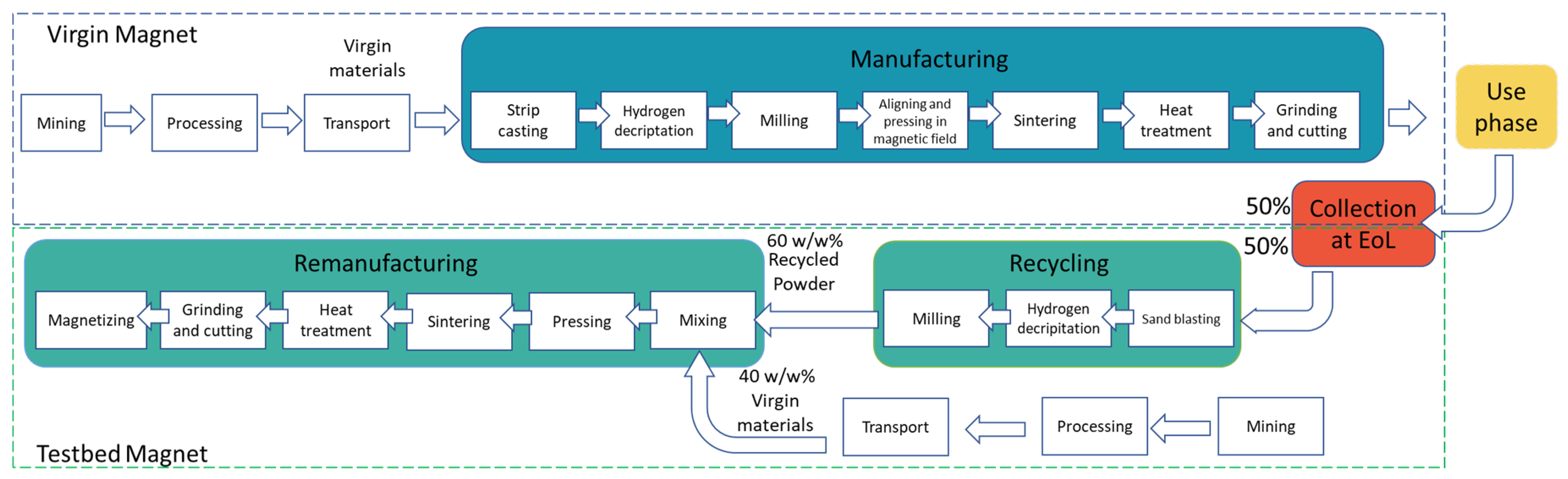
2.1.1. Product Systems under Study

This study compares the environmental impacts of two (NdDy)FeB magnets from a life cycle perspective. The former is called “virgin magnet” afterwards, and it is produced 100% from virgin materials, while the latter is called “testbed magnet” afterwards, and it is produced 60% from recycled and 40% from virgin material through a novel hydrogen decrepitation recycling process. The magnetic properties of the two magnets under study are reported in Table 1, while the material compositions are reported in Table 2.

2.1.2. Functional Unit

The function and functional unit are central elements of an LCA [35]. Without them, a meaningful and valid comparison is not possible. In the sense of an LCA, “function” means to quantitatively and qualitatively specify the analyzed object. This is generally achieved by using the functional unit that names and quantifies the qualitative and quantitative aspects of the function(s) along with the questions “what”, “how much”, “how well”, and “for how long” [33].
This study is focused on permanent magnets, so their function should be clearly stated and taken into account when choosing the functional unit [31,32]. The functional unit mainly used in the literature is the mass of the magnet. In this study, the two magnets considered for comparison share the same type of material, size, and shape because they are assumed to be used in the same electric motor. For these reasons, adopting the mass of the magnets as the functional unit would be meaningless for this study. Moreover, the functional unit should be based on the main function of the magnet.
The primary function of a magnet is to produce a magnetic field around itself. In the case of automotive applications, which are high-temperature applications, the main magnetic parameters are the magnetization coercivity Hc and the maximum energy product BHmax. The magnetization coercivity is particularly vital for motor applications because demagnetization can occur during motor operation at elevated temperatures (e.g., above 100 °C) [36]. Their high values of magnetization coercivity make REEs ideal for permanent magnet alloys [37].
Moreover, using a recycled magnet instead of a virgin one may reduce the magnet’s performance and the motor’s efficiency, and the adoption of the mass as the functional unit would not allow for the detection of this effect. In fact, to be applied again in electric motors (i.e., closed-loop recycling), the recovery of REE alloys must occur with minimum loss of properties [8,9]. Especially for high-temperature applications, such as electric motors, permanent magnets with high magnetization coercivity are required [36].
As reported in Table 3, three different functional units were investigated based on three different parameters: the mass (to compare results with the literature), the magnetization coercivity, and the maximum energy product.

2.1.3. System Boundary

LCA is conducted by defining product systems as models that describe the key elements of physical systems. After identifying the product system or systems, the system boundary must be set in order to specify which unit processes will be covered or excluded from the study.
As depicted in Figure 1, the system boundaries of both the virgin and testbed magnets include all the most relevant life cycle stages, excluding the use phase. The use phase is excluded because magnets do not constitute end products. They are generally assembled into electric motors, which are subsequently assembled into electric vehicles, which actually represent the end products.
Instead, the system boundary covers the following life cycle stages:
  • Raw material acquisition and preprocessing;
  • Manufacturing;
  • Collection at EoL;
  • Recycling of used magnets;
  • Remanufacturing.
The so-called raw material acquisition and preprocessing stage of the virgin and testbed magnets comprises the environmental burdens caused by the acquisition of virgin materials (i.e., mining, processing, and transportation). The manufacturing process is fed the virgin materials coming from the raw material acquisition and preprocessing stage, and it comprises the sub-processes in the blue box in Figure 1. Collection at the EoL refers to the transportation of the used magnet from the final user to the recycling facility. The recycling and remanufacturing processes comprise the subprocesses in the green boxes in Figure 1. The recycling process is fed used magnets and comprises sand blasting, hydrogen decrepitation, and milling. Instead, the so-called remanufacturing process is fed both recycled powder (coming from the recycling process) and virgin powder and comprises a set of sub-processes (mixing, pressing, sintering, heat treatment, grinding, and cutting and magnetizing) needed to produce the testbed magnet.

2.1.4. Allocation and Multifunctionality

According to [31], allocation is defined as the partitioning of input and output flows between the product system under study and one or more other product systems produced simultaneously. Moreover, according to [32], allocation also applies to recycling situations in which one or more unit processes are shared between the product system under study and the subsequent product system (which, for example, may benefit from recycled materials coming from the product system under study). According to [38], the allocation procedures provided by the international standards [31,32] define how to assign impacts from virgin production processes to material that is recycled and used in subsequent product systems, or, in other words, define how to model the EoL phase.
The modelling of the EoL phase has been broadly discussed methodologically within the LCA community in recent years, but there is no consensus on the single best approach [39,40]. Among the two most commonly used EoL approaches (i.e., the so-called “avoided burden” and “cut-off”), the one used in this study is the “cut-off”, or sometimes referred to as the “100:0, no credit” [41] or “recycled content” approach [38]. The general formula of the 100:0, no credit approach is reported in Equation (1). According to [38,41], this approach is characterized by the full allocation of the recycling burdens ( E r e c y c l e d ) to the product using recycled material (i.e., the testbed magnet), with no burdens from recycling operations allocated to the primary product (i.e., the virgin magnet). Also, full allocation of burdens arising from the primary manufacturing operations is given to the primary product and not to the secondary product.
Equation (2) reports the formulation applied to the virgin magnet, in which R 1 is set to zero because no recycled material is used as an input to the manufacturing process (blue box in Figure 1). Instead, Equation (3) reports the formulation applied to the testbed magnet, in which both recycled and virgin materials are used, and R1 is equal to 0.60. The cut-off approach was slightly modified in Equations (2) and (3) adding the term 0.5 × E t r a n s . Using this term, the emissions from the collection at EoL are assumed to be equally shared between the two products under study, hypothesizing closed-loop recycling in which the testbed magnet is directly recycled from the virgin magnet under study.
E F c u t o f f = 1 R 1 × E V + R 1 × E r e c y c l e d + 1 R 2 × E D
E F v i r g i n = E V + 0.5 × E t r a n s + 1 R 2 × E D
E F t e s t b e d = 0.5 × E t r a n s + 1 R 1 × E V + R 1 × E r e c y c l e d
EF = emissions and resources consumed (per unit of analysis) arising from the acquisition, pre-processing, and EoL stages of the product life cycle.
EV = emissions and resources consumed (per unit of analysis) arising from the acquisition and pre-processing of virgin material.
Erecycled = emissions and resources consumed (per unit of analysis) arising from the recycling process of the material, excluding collection, sorting, and transportation processes.
Etrans = emissions and resources consumed (per unit of analysis) arising from the collection, sorting, and transport of the EoL magnets.
ED = emissions and resources consumed (per unit of analysis) arising from disposal of waste material (e.g., landfilling, incineration).
R1 (dimensionless) = recycled fraction of material, which is the proportion of the material in the secondary product that has been recycled in a previous system.
R2 (dimensionless) = recycling fraction of material, which is the proportion of the material in the primary product that will be recycled in a subsequent system.
Equations (1)–(3) cover the raw material acquisition, pre-processing, and EoL stages. The total impact of the virgin magnet is given by the sum of E F v i r g i n and the environmental impact of the manufacturing stage, depicted using a blue box in Figure 1. Similarly, the total impact of the testbed magnet is given by the sum of E F t e s t b e d and the environmental impact of the remanufacturing stage, depicted using a green box in Figure 1.

2.1.5. Impact Assessment Method

The impact assessment method used in this study is the Environmental Footprint (EF) 3.0 method, which is the Life Cycle Impact Assessment (LCIA) method recommended in the framework of the Product Environmental Footprint (PEF) method developed by the European Commission [42]. The software used in this study is SimaPro v9.4.0.3. The complete set of impact categories included in this method is reported in Table 4.

2.2. Life Cycle Inventories

2.2.1. Virgin Magnet Manufacturing Process

The virgin magnet manufacturing process was modelled based on [43], in which transparent data representative of high-volume production in a factory in an industrialized country are reported. Some modifications were made to the dataset of [43] to align the material composition of the magnet with the one considered in this study and reported in Table 2. The entire manufacturing process is assumed to occur in China (Table S6). For Rare Earth Oxides (REOs) mining, neodymium oxide is assumed to be mined from rare earth carbonate concentrate in the Fujian region of China. After mining, dysprosium enters the magnet manufacturing process directly as dysprosium oxide, while neodymium oxide is reduced to its pure metal form by means of fused salt electrolysis [43]. During this process (Table S4), neodymium oxide is fed to and dissolved in a fluoride electrolyte, graphite is consumed from the anode, and pure metal deposits occur at the cathode [43]. Boron, instead, is added as boron carbide, while electrolytic iron of high purity is used (Table S5) [43]. After the processing of REOs, metal ingots or powders are melted together to form an alloy of neodymium, iron, and boron by means of strip casting [36,43]. At the end of strip casting, the molten alloy ends in the form of flakes [36,43]. After strip casting, the process goes on with hydrogen decrepitation and jet milling, where the flakes are pulverized into the form of a fine powder [36,43]. Then, the powder is aligned and pressed in a magnetic field [36,43]. The compacted material is vacuum sintered, and the magnet is obtained via grinding, slicing, and drilling [36,43]. Lastly, dysprosium is added using grain boundary diffusion, a final coating is applied via electroplating, and the magnet is magnetized. All the LCIs and the adopted background datasets are reported in Tables S4–S6 and S17.

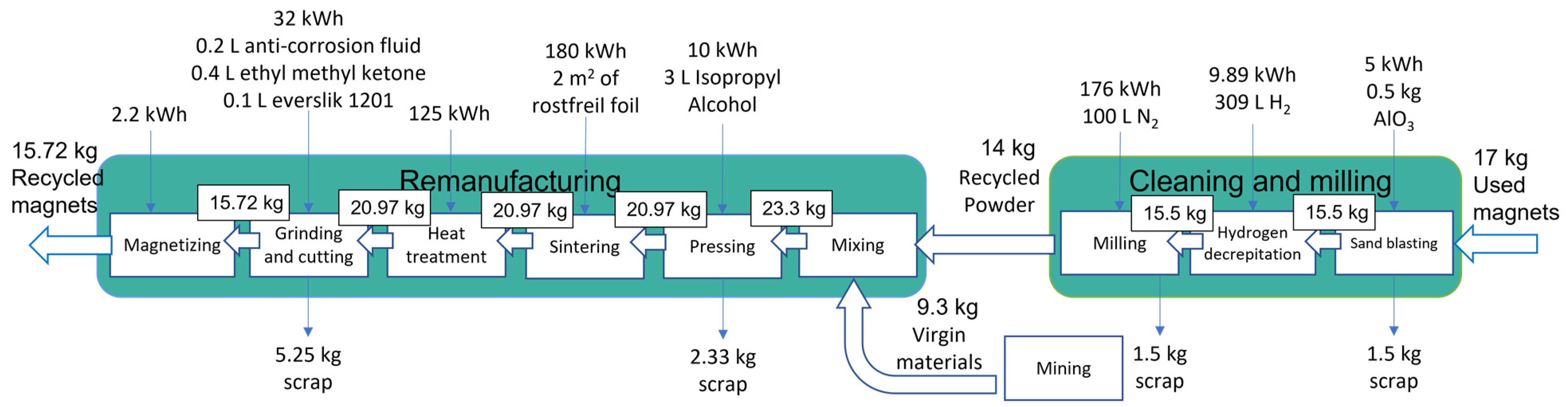
2.2.2. Testbed Magnet and Novel Recycling Process
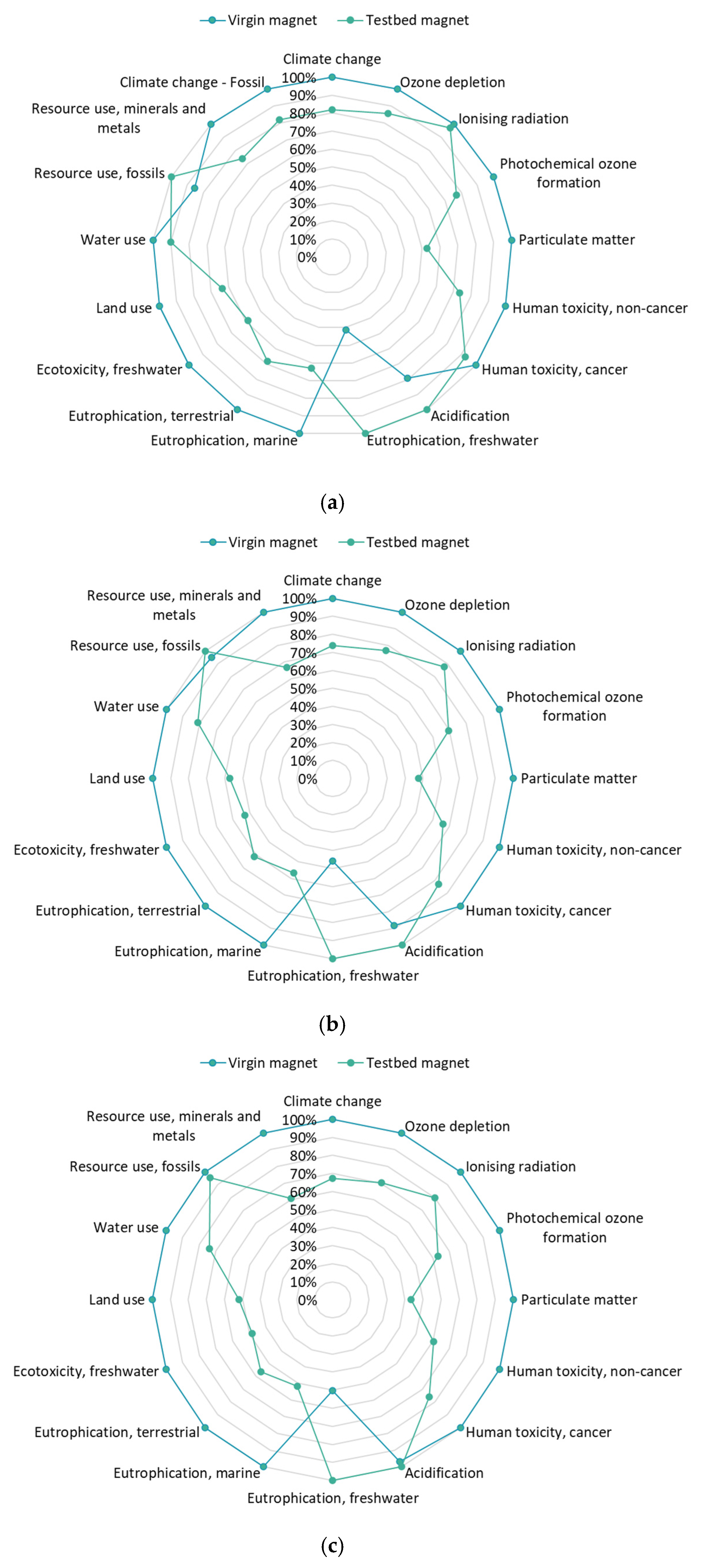
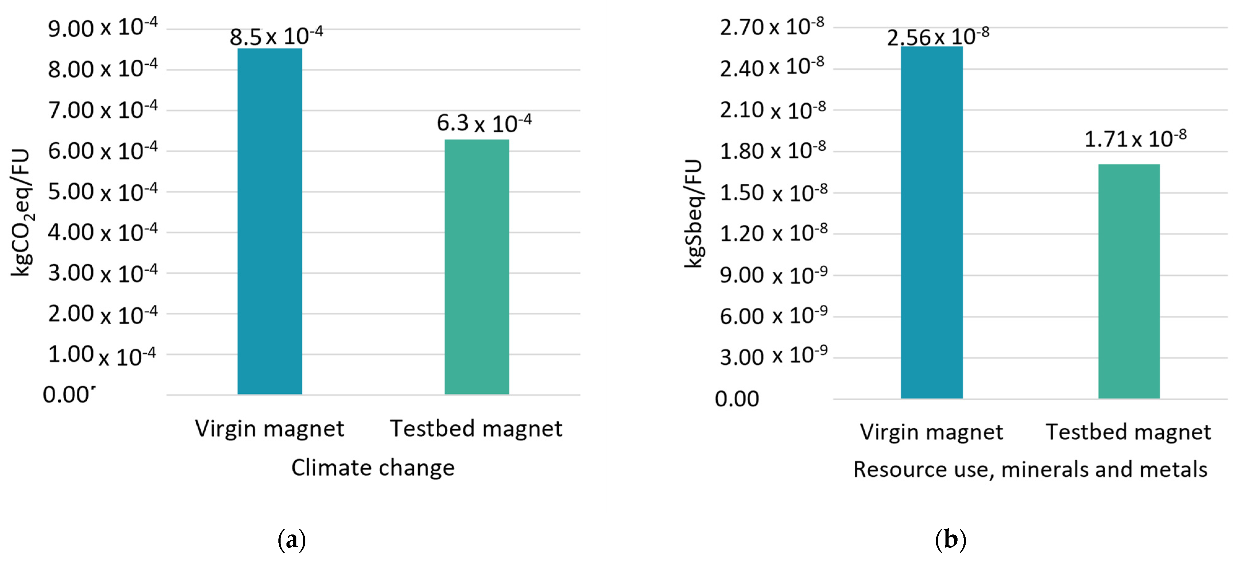
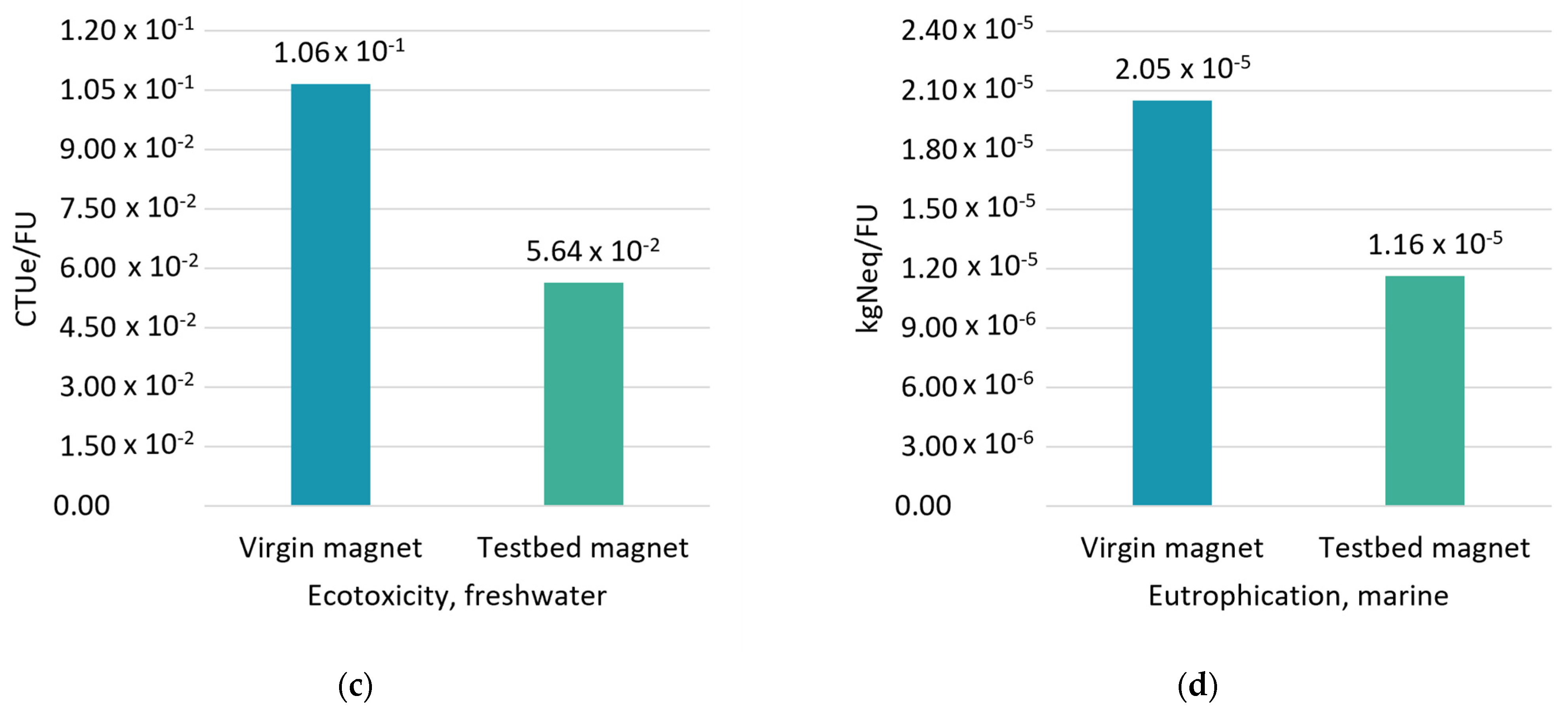
The experimental demonstration of the novel hydrogen-decrepitation-based recycling process was developed on a laboratory scale in Slovenia (SI). The process began with the transportation of 17 kg of EoL permanent magnets from China to Slovenia. Then, sandblasting was used to remove the oxidation layer and other contaminants from the surface of the magnets. To provide a comprehensive cleaning of the EoL magnets’ surfaces, the sandblaster was operated twice at half its capacity (i.e., 8.5 kg each time). Aluminum oxide was utilized in the sandblasting process. Following sandblasting, the procedure resembles that which is applied to virgin alloys. First, the magnets were subjected to a hydrogen decrepitation reactor utilizing hydrogen to crush the material. Many variables influence the hydrogen decrepitation process, such as magnet chemical composition, microstructure, particle size, and pressure cycling [17]. Then, the pulverized material was further milled in 100 L of nitrogen gas. The milled powder was combined with a certain amount of virgin materials, i.e., a milled alloy of pure neodymium, dysprosium, and other elements. The powder was subsequently pressed and sintered. In order to achieve the desired magnetic characteristics, magnets were subjected to a heat treatment to obtain a suitable microstructure. Following this, the magnets were fabricated and shaped using grinding and cutting. After magnetizing, an epoxy coating was applied. The magnet material flows, ancillary material flows, and energy flows associated with the recycling process are depicted in Figure 2. The recycled sample exhibited a coercivity of 922.5 kA/m, a remanence value of 1190 T and an energy product of 273 kJ/m3.
When using EoL magnets as an input material for the recycling process, permanent magnets must first be extracted from their end products, such as electric motors. The extraction process of permanent magnets was assumed to occur successfully, and no burden was given for this process because, despite some trials made in the literature [18,25], this is an open research point and its effectiveness, energy consumption, and material losses would depend on the extraction process.
All the life cycle inventories related to the testbed magnet are reported in the Supplementary Material in Tables S7–S16 and S18.
Because the recycling process has been conducted at laboratory scale in this project, the focus has been on proving process feasibility rather than optimizing energy and material utilization. Therefore, the margins of process optimization and, consequently, additional reductions in the environmental impacts with respect to virgin magnet production are very wide. Reducing material losses and energy consumption during the recycling process would significantly increase the environmental benefit of recycled magnets. To have a first estimation of the reduction in environmental performance thanks to the optimization of the recycling process, certain assumptions have been made, as reported in Tables S1–S3.

3. Results

Table 5 and Figure 3 show the comparison of the characterization results of climate change between the two magnets under study, varying the functional units (i.e., mass, magnetization coercivity, and maximum energy product). Results for the virgin magnet are reported in blue, while results for the testbed magnet are reported in green.
When a mass-based functional unit is adopted, results reveal that recycling permanent magnets through hydrogen decrepitation (i.e., testbed magnet) allows for a reduction in climate change of around 18%, as depicted in Figure 3. Nevertheless, given that the two magnets have identical masses, employing a mass-based functional unit for the comparison is meaningless as it equally reduces both results. In spite of this, the results obtained utilizing the mass-based functional unit were computed and reported to compare them with the existing literature, with the mass-based functional unit being the most used in other studies. In [44], a comparison between magnet recycling and production using virgin materials reveals a saving in terms of CO2eq of 55%, while [11] reports a CO2eq saving ranging from 18 to 76%.
When a magnetization coercivity-based functional unit is adopted, results reveal that recycling permanent magnets through hydrogen decrepitation allows for a reduction in climate change of around 26% (Figure 3). The saving is higher than in the previous case because the virgin magnet is characterized by a magnetization coercivity Hc of 830 kA/m, while the testbed magnet has 922.5 kA/m.
Lastly, adopting a maximum energy product-based functional unit and recycling permanent magnets through hydrogen decrepitation allows for a reduction in climate change of around 33% (Figure 3). The saving is the highest with respect to the previous cases because the virgin magnet is characterized by a maximum energy product BHmax of 224 kJ/m, while the testbed magnet has 273 kJ/m.
The radar diagrams in Figure 4 show the comparison of the environmental performances between the two magnets under study for a broad range of environmental impacts and varying functional units. Results for the virgin magnet are reported in blue, while results for the testbed magnet are reported in green. The testbed magnet performs significantly better than the virgin magnet in almost all the impact categories under study. In the categories “ionizing radiation” and “human toxicity, cancer” the difference between the two magnets is not significant when the mass-based functional unit is applied (Figure 4a). In the category “use of fossil resources”, the virgin magnet significantly outperforms the testbed magnet when the mass-based functional unit is applied (Figure 4a), while the difference is not significant for the other functional units. In the category “acidification”, the virgin magnet significantly outperforms the testbed magnet for all the functional units, except for the coercivity-based functional unit where the difference is not significant (Figure 4c). Lastly, in the categories “freshwater eutrophication” and “water use”, the virgin magnet significantly outperforms the testbed magnet for all the functional units (Figure 4a–c).
Figure 5 and Table 6 show the environmental impacts of the six most relevant impact categories identified through the process of normalization and weighting of the EF method. Listing the categories in descending order of impact, the ones that constitute at least 80% of the total score were considered. According to Figure 5, the testbed magnet performs significantly better than the virgin magnet in the majority of the most relevant impact categories, namely climate change, use of mineral and metal resources, freshwater ecotoxicity, and marine eutrophication.
For climate change, the saving is mainly due to electricity consumption during the production of the virgin magnet in China and to the production of pure neodymium, which is present in the virgin magnet in a higher amount with respect to the testbed magnet.
For the use of mineral and metal resources, freshwater ecotoxicity, and marine eutrophication, the saving is mainly due to the avoided mining process of neodymium oxide in the testbed magnet.
For the use of fossil resources, the higher impact of the testbed magnet is related to hydrogen production.
When it comes to freshwater eutrophication, the testbed magnet has the highest impact because of the mining process of lignite involved in the Slovenian electricity production mix.

4. Conclusions

The LCA methodology is applied in this study to compare the environmental impacts of two (NdDy)FeB magnets. The former is produced entirely from virgin materials, while the latter is produced 60% from recycled and 40% from virgin material through a novel hydrogen decrepitation recycling process.
Furthermore, three different functional units based on three different parameters were investigated: mass (the most commonly used one in other studies), magnetization coercivity, and maximum energy product. By adopting the magnet mass as a functional unit, recycling permanent magnets allows for a reduction in climate change of around 18%. Nevertheless, the two magnets have the same mass, so the adoption of the mass-based functional unit is meaningless in this context. By adopting the magnetization coercivity as a functional unit, recycling permanent magnets allows for a reduction in climate change of around 26%, while by adopting the maximum energy product as a functional unit, recycling permanent magnets allows for a reduction in climate change of around 33%. Lastly, by adopting the magnetization coercivity as a functional unit, the testbed magnet performed significantly better than the virgin magnet in four out of the six most relevant impact categories.
Also, it must be pointed out that the recycling process is still at a laboratory scale, and it can be further optimized, and the environmental impacts can be further reduced. This LCA study was carried out to identify potential environmental hotspots in the early stages of research and development and to provide a rough indication of the comparison between the environmental impacts of the virgin permanent magnet production route and those of the hydrogen decrepitation recycling route. This paper’s conclusions should be interpreted as an initial assessment of the potential impacts of the process under development, which may serve as the groundwork for future research.
Future research should focus on improving the applicability of the whole technique in the electric vehicle industry. In fact, to be recycled, permanent magnets must first be extracted from electric motors. Nowadays, magnets are not pre-dismantled from electric motors, and they are sent to the shredder, where they are lost to ferrous or nonferrous scrap. In the present study, the extraction process of permanent magnets was assumed to occur successfully, and no burden was given for this process. However, this is an open research point. The effectiveness of the extraction process depends on how the motor is designed to enhance the magnet extraction and energy consumption and material losses would depend on the extraction procedure. If successfully put in place, the dismantling-before-shredding technique and then recycling technique for permanent magnets can be beneficial for the electric vehicle industry but also for other sectors (i.e., generators of wind turbines where permanent magnets are found as well as consumer electronics and household appliances).

Supplementary Materials

The following supporting information can be downloaded at: https://www.mdpi.com/article/10.3390/en17040908/s1. Table S1. Assumptions made to optimize the recycling process in terms of material losses; Table S2. Assumptions made to optimize the recycling process in terms of energy consumption; Table S3. Assumptions made to optimize the recycling process in terms of ancillary material consumption; Table S4. LCI of the production of 1 kg of pure Neodymium; Table S5. LCI of the production of 1 kg of electrolytic Iron; Table S6. LCI of the production of 1 kg of virgin Nd(Dy)FeB magnet; Table S7. LCI of sand blasting process; Table S8. LCI of hydrogen decrepitation treatment; Table S9. LCI for 1 kg of fresh virgin material added during the recycling process; Table S10. LCI of milling treatment; Table S11. LCI of mixing process; Table S12. LCI of pressing process; Table S13. LCI of sintering process; Table S14. LCI of heat-treatment; Table S15. LCI of grinding and cutting process; Table S16. LCI of magnetizing process; Table S17. LCI of the life cycle of the virgin magnet; Table S18. LCI of the production through magnet-to-magnet recycling of 1 testbed Nd(Dy)FeB magnet; Table S19. Normalized and weighted results (the most relevant impact categories for each product system are highlighted in yellow); Table S20. Characterized results w/o FU; Table S21. Characterized results per mass-based FU (Figure 4a); Table S22. Characterized results per coercivity-based FU (Figure 4b); Table S23. Characterized results per energy-product-based FU (Figure 4c); Table S24. Results of the most relevant impact categories per different FU (Figure 5); Figure S1. Probability distributions for the virgin magnet’s characterized results and the six most relevant impact categories: (a) Climate change; (b) Use of fossil resources; (c) Freshwater ecotoxicity; (d) Marine eutrophication; (e) Freshwater eutrophication; (f) Use of mineral and metal resources; Table S25. Monte Carlo analysis results for the virgin magnet and the six most relevant impact categories; Figure S2. Probability distributions for the testbed magnet’s characterized results and the six most relevant impact categories: (a) Climate change; (b) Use of fossil resources; (c) Freshwater ecotoxicity; (d) Marine eutrophication; (e) Freshwater eutrophication; (f) Use of mineral and metal resources; Table S26. Monte Carlo analysis results for the testbed magnet and the six most relevant impact categories. Reference [43] cited in Supplementary Materials.

Author Contributions

Conceptualization, A.A.; methodology, A.A.; formal analysis, A.A. and T.C.; investigation, A.A. and T.C.; software, A.A. and T.C.; writing—original draft preparation, A.A.; writing—review and editing, E.S.; supervision, E.S. All authors have read and agreed to the published version of the manuscript.

Funding

This research was funded by the European Institute of Technology (EIT) under the grant agreement 0074 Politecnico di Torino–Internal Agreement–Grant 2022.

Data Availability Statement

Data are contained within the article and Supplementary Materials.

Acknowledgments

The authors want to acknowledge the Center for Automotive Research and Sustainable mobility (CARS) of Politecnico di Torino.

Conflicts of Interest

The authors declare no conflict of interest.

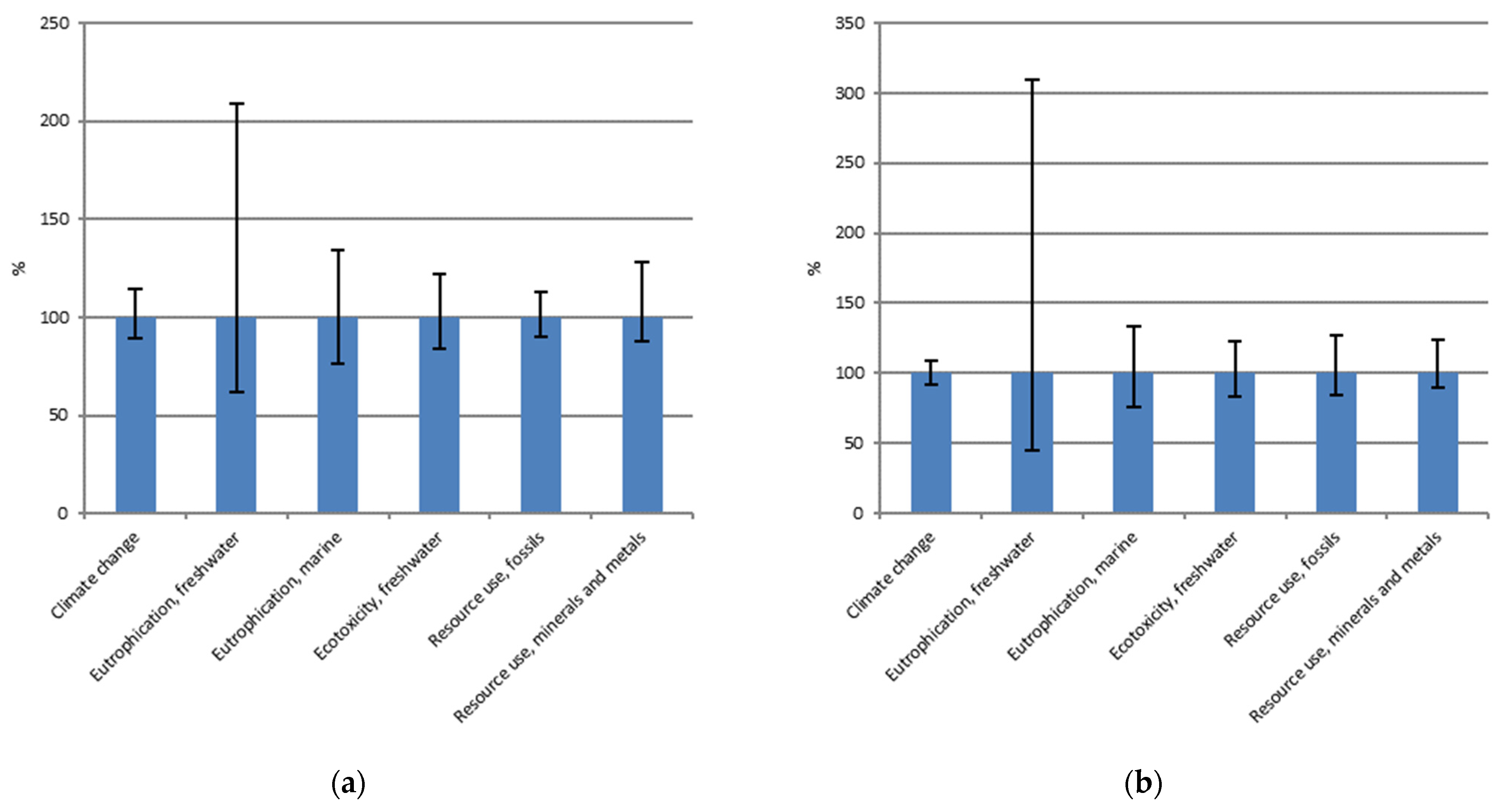
Appendix A. Uncertainty Assessment through Monte Carlo Analysis

A Monte Carlo analysis was conducted to measure LCA result uncertainty and provide more rigorous conclusions. To converge on a mean value, 10,000 iterations were run. The virgin and the testbed magnets were first assessed in stand-alone analyses (Figure A1) and then a comparative analysis was conducted (Table A1). In Figure A1, the vertical lines show the uncertainty ranges for each category, while each range expresses 95% interval confidence.
Figure A1. Uncertainty analysis conducted on the characterized results of the six most relevant impact categories considering the following: (a) The virgin magnet; (b) The testbed magnet.
Energies 17 00908 g0a1
Table A1. Monte Carlo Analysis. Comparison between virgin and testbed magnets considering the six most relevant impact categories. Y = YES; N = NO.
Deterministic LCAMonte Carlo Analysis
Impact CategoryDoes the Testbed Magnet Have a Lower Impact than the Virgin Magnet? Percentage of Runs in Which the Testbed
Magnet Has a Lower
Impact than the Virgin One
Climate changeY99.5%
Resource use, fossilsN-
Eutrophication, freshwaterN-
Ecotoxicity, freshwaterY99.9%
Eutrophication, marineY98.8%
Resource use, minerals, and metalsY98.6%

References

  1. Climate Change: What the EU Is Doing. Available online: https://www.consilium.europa.eu/en/policies/climate-change/ (accessed on 23 January 2024).
  2. The Paris Agreement|UNFCCC. Available online: https://unfccc.int/process-and-meetings/the-paris-agreement (accessed on 23 January 2024).
  3. Gauß, R.; Burkhardt, C.; Carencotte, F.; Gasparon, M.; Gutfleisch, O.; Higgins, I.; Karajić, M.; Klossek, A.; Mäkinen, M.; Schäfer, B.; et al. Rare Earth Magnets and Motors: A European Call for Action; A Report by the Rare Earth Magnets and Motors Cluster of the European Raw Materials Alliance; European Raw Materials Alliance: Berlin, Germany, 2021. [Google Scholar]
  4. Yang, Y.; Walton, A.; Sheridan, R.; Güth, K.; Gauß, R.; Gutfleisch, O.; Buchert, M.; Steenari, B.-M.; Van Gerven, T.; Jones, P.T.; et al. REE Recovery from End-of-Life NdFeB Permanent Magnet Scrap: A Critical Review. J. Sustain. Metall. 2017, 3, 122–149. [Google Scholar] [CrossRef]
  5. Arshi, P.S.; Vahidi, E.; Zhao, F. Behind the scenes of clean energy—The environmental footprint of rare earth products. ACS Sustain. Chem. Eng. 2018, 6, 3311–3320. [Google Scholar] [CrossRef]
  6. Becci, A.; Beolchini, F.; Amato, A. Sustainable Strategies for the Exploitation of End-of-Life Permanent Magnets. Processes 2021, 9, 857. [Google Scholar] [CrossRef]
  7. USEPA. Rare Earth Elements: A Review of Production, Processing, Recycling, and Associated Environmental Issues; USEPA: Washington, DC, USA, 2012. [Google Scholar]
  8. Zakotnik, M.; Tudor, C.O. Commercial-scale recycling of NdFeB-type magnets with grain boundary modification yields products with ‘designer properties’ that exceed those of starting materials. Waste Manag. 2015, 44, 48–54. [Google Scholar] [CrossRef] [PubMed]
  9. Koltun, P.; Tharumarajah, A. Life Cycle Impact of Rare Earth Elements. ISRN Metall. 2014, 2014, 907536. [Google Scholar] [CrossRef]
  10. Bailey, G.; Joyce, P.J.; Schrijvers, D.; Schulze, R.; Sylvestre, A.M.; Sprecher, B.; Vahidi, E.; Dewulf, W.; Van Acker, K. Review and new life cycle assessment for rare earth production from bastnäsite, ion adsorption clays and lateritic monazite. Resour. Conserv. Recycl. 2020, 155, 104675. [Google Scholar] [CrossRef]
  11. Wang, Y.; Sun, B.; Gao, F.; Chen, W.; Nie, Z. Life cycle assessment of regeneration technology routes for sintered NdFeB magnets. Int. J. Life Cycle Assess. 2022, 27, 1044–1057. [Google Scholar] [CrossRef]
  12. Bailey, G.; Mancheri, N.; Van Acker, K. Sustainability of Permanent Rare Earth Magnet Motors in (H)EV Industry. J. Sustain. Metall. 2017, 3, 611–626. [Google Scholar] [CrossRef]
  13. Heim, M.; Wirth, F.; Boschert, L.; Fleischer, J. An Approach for the Disassembly of Permanent Magnet Synchronous Rotors to Recover Rare Earth Materials. Procedia CIRP 2023, 116, 71–76. [Google Scholar] [CrossRef]
  14. Bobba, S.; Eynard, U.; Maury, T.; Ardente, F.; Blengini, G.A.; Mathieux, F. Circular Input Rate: Novel indicator to assess circularity performances of materials in a sector—Application to rare earth elements in e-vehicles motors. Resour. Conserv. Recycl. 2023, 197, 107037. [Google Scholar] [CrossRef]
  15. Alonso, E.; Sherman, A.M.; Wallington, T.J.; Everson, M.P.; Field, F.R.; Roth, R.; Kirchain, R.E. Evaluating Rare Earth Element Availability: A Case with Revolutionary Demand from Clean Technologies. Environ. Sci. Technol. 2012, 46, 3406–3414. [Google Scholar] [CrossRef]
  16. Jin, H.; Frost, K.; Sousa, I.; Ghaderi, H.; Bevan, A.; Zakotnik, M.; Handwerker, C. Life cycle assessment of emerging technologies on value recovery from hard disk drives. Resour. Conserv. Recycl. 2020, 157, 104781. [Google Scholar] [CrossRef]
  17. Eldosouky, A.; Škulj, I. Recycling of SmCo 5 magnets by HD process. J. Magn. Magn. Mater. 2018, 454, 249–253. [Google Scholar] [CrossRef]
  18. Coelho, F.; Abrahami, S.; Yang, Y.; Sprecher, B.; Li, Z.; Menad, N.-E.; Bru, K.; Marcon, T.; Rado, C.; Saje, B.; et al. Upscaling of Permanent Magnet Dismantling and Recycling through VALOMAG Project. Mater. Proc. 2021, 5, 74. [Google Scholar] [CrossRef]
  19. Eldosouky, A.; Ikram, A.; Mehmood, M.F.; Xu, X.; Šturm, S.; Žužek Rožman, K.; Škulj, I. Hydrogen Decrepitation and Spark Plasma Sintering to Produce Recycled SmCo5 Magnets with High Coercivity. IEEE Magn. Lett. 2018, 9, 5503504. [Google Scholar] [CrossRef]
  20. Walton, A.; Yi, H.; Rowson, N.A.; Speight, J.D.; Mann, V.S.J.; Sheridan, R.S.; Bradshaw, A.; Harris, I.R.; Williams, A.J. The use of hydrogen to separate and recycle neodymium–iron–boron-type magnets from electronic waste. J. Clean. Prod. 2015, 104, 236–241. [Google Scholar] [CrossRef]
  21. Zakotnik, M.; Harris, I.R.; Williams, A.J. Multiple recycling of NdFeB-type sintered magnets. J. Alloys Compd. 2009, 469, 314–321. [Google Scholar] [CrossRef]
  22. Wulf, C.; Zapp, P.; Schreiber, A.; Marx, J.; Schlör, H. Lessons Learned from a Life Cycle Sustainability Assessment of Rare Earth Permanent Magnets. J. Ind. Ecol. 2017, 21, 1578–1590. [Google Scholar] [CrossRef]
  23. Bailey, G.; Orefice, M.; Sprecher, B.; Önal, M.A.R.; Herraiz, E.; Dewulf, W.; Van Acker, K. Life cycle inventory of samarium-cobalt permanent magnets, compared to neodymium-iron-boron as used in electric vehicles. J. Clean. Prod. 2021, 286, 125294. [Google Scholar] [CrossRef]
  24. Sprecher, B.; Xiao, Y.; Walton, A.; Speight, J.; Harris, R.; Kleijn, R.; Visser, G.; Kramer, G.J. Life Cycle Inventory of the Production of Rare Earths and the Subsequent Production of NdFeB Rare Earth Permanent Magnets. Environ. Sci. Technol. 2014, 48, 3951–3958. [Google Scholar] [CrossRef] [PubMed]
  25. Schulze, R.; Abbasalizadeh, A.; Bulach, W.; Schebek, L.; Buchert, M. An Ex-ante LCA Study of Rare Earth Extraction from NdFeB Magnet Scrap Using Molten Salt Electrolysis. J. Sustain. Metall. 2018, 4, 493–505. [Google Scholar] [CrossRef]
  26. Tabosa da Silva, A.L. Ex-Ante LCA of a Hydrometallurgical Route using Weak Acid for Recycling of REEs from EOL HDD’s NdFeB Permanent Magnet. Master’s Thesis, Leiden University, Leiden, The Netherlands, 2021. [Google Scholar]
  27. Nordelöf, A.; Alatalo, M. A Scalable Life Cycle Inventory of an Automotive Power Electronic Inverter Unit; Chalmers University of Technology: Gothenburg, Sweden, 2018. [Google Scholar]
  28. Chowdhury, N.A.; Deng, S.; Jin, H.; Prodius, D.; Sutherland, J.W.; Nlebedim, I.C. Sustainable Recycling of Rare-Earth Elements from NdFeB Magnet Swarf: Techno-Economic and Environmental Perspectives. ACS Sustain. Chem. Eng. 2021, 9, 15915–15924. [Google Scholar] [CrossRef]
  29. Buchert, M.; Sutter, J.; Merz, C. Ökobilanz der Recyclingverfahren; Öko-Institut e.V.: Darmstadt, Germany, 2014. [Google Scholar]
  30. Bast, U.; Blank, R.; Buchert, M.; Elwert, T.; Finstelwarder, F.; Hornig, G.; Klier, T.; Langkau, S.; Marscheider-Weidemann, S.; Muller, J.O.; et al. Recycling von Komponenten und Strategischen Metallen aus Elektrischen Fahrantrieben; MORE (Motor Recycling): Munchen, Germany, 2014. [Google Scholar]
  31. ISO 14040:2006; Environmental Management. Life Cycle Assessment. Principles and Framework. ISO: Geneva, Switzerland, 2006; ISBN 978-0-580-48992-1.
  32. ISO 14044:2006; Environmental Management. Life Cycle Assessment. Requirements and Guidelines. ISO: Geneva, Switzerland, 2018; ISBN 978-0-539-00856-2.
  33. Joint Research Centre. International Reference Life Cycle Data System (ILCD) Handbook: General Guide for Life Cycle Assessment: Detailed Guidance; Publications Office: Luxembourg, 2010. [Google Scholar]
  34. Joint Research Centre. International Reference Life Cycle Data System (ILCD) Handbook—Framework and Requirements for Life Cycle Impact Assessment Models and Indicators; EUR 24586 EN; Publications Office of the European Union: Luxembourg, 2010. [Google Scholar]
  35. Vittorio, N.D.; Accardo, A.; Spessa, E.; Viscido, L.; Tam, E. LCA and LCC of a Li-Ion Battery Pack for Automotive Application; SAE International: Warrendale, PA, USA, 2023. [Google Scholar]
  36. Zakotnik, M.; Tudor, C.O.; Peiró, L.T.; Afiuny, P.; Skomski, R.; Hatch, G.P. Analysis of energy usage in Nd–Fe–B magnet to magnet recycling. Environ. Technol. Innov. 2016, 5, 117–126. [Google Scholar] [CrossRef]
  37. Adibi, N.; Lafhaj, Z.; Payet, J. New resource assessment characterization factors for rare earth elements: Applied in NdFeB permanent magnet case study. Int. J. Life Cycle Assess. 2019, 24, 712–724. [Google Scholar] [CrossRef]
  38. Global Battery Alliance. Greenhouse Gas Rulebook; Global Battery Alliance: Brussels, Brussels, 2023. [Google Scholar]
  39. European Commission; DG Climate Action. Determining the Environmental Impacts of Conventional and Alternatively Fuelled Vehicles through LCA; Publications Office: Luxemburg, 2020. [Google Scholar]
  40. Accardo, A.; Dotelli, G.; Miretti, F.; Spessa, E. End-of-Life Impact on the Cradle-to-Grave LCA of Light-Duty Commercial Vehicles in Europe. Appl. Sci. 2023, 13, 1494. [Google Scholar] [CrossRef]
  41. Allacker, K.; Mathieux, F.; Pennington, D.; Pant, R. The search for an appropriate end-of-life formula for the purpose of the European Commission Environmental Footprint initiative. Int. J. Life Cycle Assess. 2017, 22, 1441–1458. [Google Scholar] [CrossRef]
  42. Zampori, L.; Pant, R. Suggestions for Updating the Product Environmental Footprint (PEF) Method; Publications Office of the European Union: Luxembourg, 2019. [Google Scholar]
  43. Nordelöf, A.; Tillman, A.-M. A scalable life cycle inventory of an electrical automotive traction machine—Part II: Manufacturing processes. Int. J. Life Cycle Assess. 2018, 23, 295–313. [Google Scholar] [CrossRef]
  44. Jin, H.; Afiuny, P.; McIntyre, T.; Yih, Y.; Sutherland, J.W. Comparative Life Cycle Assessment of NdFeB Magnets: Virgin Production versus Magnet-to-Magnet Recycling. Procedia CIRP 2016, 48, 45–50. [Google Scholar] [CrossRef]
Figure 1. System boundaries of virgin and testbed magnets.
Energies 17 00908 g001
Figure 2. Raw material, ancillary material, and energy flows during the recycling process.
Energies 17 00908 g002
Figure 3. Comparison between the virgin magnet and the testbed magnet considering the characterized results of the following: (a) Climate change; (b) Use of mineral and metal resources; (c) Freshwater ecotoxicity; (d) Marine eutrophication. Results are shown in percentages and varying the functional unit: 1 kg of mass, 1 kA/m of magnetization coercivity, and 1 kJ/m3 of maximum energy product of a (NdDy)FeB magnet used for EV applications.
Energies 17 00908 g003
Figure 4. Comparison of the environmental performances of the two magnets under study adopting the follows as the functional unit: (a) 1 kg of a (NdDy)FeB magnet used for EV applications; (b) 1 kA/m of magnetization coercivity of a (NdDy)FeB magnet used for EV applications; (c) 1 kJ/m3 of maximum energy product of a (NdDy)FeB magnet used for EV applications.
Energies 17 00908 g004
Figure 5. Comparison of the environmental impacts of the two magnets being studied using 1 kA/m of magnetization coercivity as the functional unit and focusing on the four impact categories in which the testbed magnet outperforms the virgin magnet: (a) Climate change; (b) Use of mineral and metal resources; (c) Freshwater ecotoxicity; (d) Marine eutrophication.
Energies 17 00908 g005aEnergies 17 00908 g005b
Table 1. Magnetic properties of the products under study.
VirginTestbed
Magnetization coercivity Hc (kA/m)830922.5
Remanence Br (T)10761190
Maximum energy product BHmax (KJ/m3)224273
Polarization coercivity Hj (kA/m)23751265
Permeability µr1.031,03
Curie temperature Tc (°C)340340
Oxygen amount (%)0.110.32
Table 2. Material compositions of the products under study.
VirginTestbed
Neodymium16.64%21.37%
Iron67.34%66.33%
Boron0.91%0.92%
Cobalt1.09%1.95%
Dysprosium7.05%4.63%
Praseodymium5.86%3.93%
Aluminum0.46%0.42%
Gallium0.65%0.45%
Table 3. Investigated functional units.
ParameterFunctional Unit
Magnetization coercivity1 kA/m of magnetization coercivity of a (NdDy)FeB magnet used for EV applications
Maximum energy product1 kJ/m3 of maximum energy product of a (NdDy)FeB magnet used for EV applications
Mass1 kg of a (NdDy)FeB magnet used for EV applications
Table 4. Set of impact categories included in the EF3.0 method.
Impact CategoryUnits
AcidificationMole H+ eq.
Climate Change—totalkg CO2 eq.
Ecotoxicity, freshwater—totalCTUe
Eutrophication—freshwater, marinekg P eq., kg N eq.
Eutrophication—terrestrialMole N eq.
Human toxicity, cancer—totalCTUh
Human toxicity, non-cancer—totalCTUh
Ionizing radiation, human healthkBq U235
Land UsePt
Ozone depletionkg CFC-11 eq.
Particulate matterDisease incidences
Photochemical ozone formation, human healthkg NMVOC eq.
Resource use, fossilsMJ
Resource use, minerals, and metalskg Sb eq.
Water Usem3
Table 5. Comparison of the characterization results of climate change in kgCO2eq/FU between the virgin magnet and the testbed magnet varying FU: 1 kg of mass, 1 kA/m of magnetization coercivity, and 1 kJ/m3 of maximum energy product.
Functional UnitVirgin MagnetTestbed Magnet
Mass4.66 × 1013.82 × 101
Magnetization coercivity8.54 × 10−46.29 × 10⁻⁴
Maximum energy product3.16 × 10−32.13 × 10⁻³
Table 6. Comparison of the environmental impacts of the two magnets being studied using 1 kA/m of magnetization coercivity as the functional unit and focusing on the six most relevant impact categories.
Impact CategoryVirgin MagnetTestbed Magnet
Climate change8.54 × 10−46.29 × 10⁻⁴
Resource use, fossils9.33 × 10−39.81 × 10⁻³
Eutrophication, freshwater2.56 × 10−75.57 × 10⁻⁷
Ecotoxicity, freshwater1.06 × 10−15.64 × 10⁻²
Eutrophication, marine2.05 × 10−51.16 × 10⁻⁵
Resource use, minerals, and metals2.56 × 10−81.71 × 10⁻⁸
Disclaimer/Publisher’s Note: The statements, opinions and data contained in all publications are solely those of the individual author(s) and contributor(s) and not of MDPI and/or the editor(s). MDPI and/or the editor(s) disclaim responsibility for any injury to people or property resulting from any ideas, methods, instructions or products referred to in the content.

