Article

Aliasing Suppression Method for a Three-Phase Grid-Connected Photovoltaic Inverter Based on Multi-Sampling and Mean Filtering

1
Sungrow Power Supply Co., Ltd., Hefei 230088, China
2
Department of Electrical Engineering, Shanghai Maritime University, Shanghai 201306, China
*
Author to whom correspondence should be addressed.
Energies 2024, 17(4), 907; https://doi.org/10.3390/en17040907
Submission received: 26 November 2023 / Revised: 15 January 2024 / Accepted: 9 February 2024 / Published: 15 February 2024
(This article belongs to the Section A2: Solar Energy and Photovoltaic Systems)

Abstract

:
In order to reduce the sampling delay and improve bandwidth, sability margin, and the robustness of the active damping in LCL-filtered grid-connected inverters, real-time sampling provides a convenient method. However, aliasing is easily introduced in the control loop because of high-frequency switching harmonics, resulting in a rise in low-order harmonics. To address the challenge of aliasing under real-time sampling, a new method based on multisampling and mean filtering is proposed by combining the proposed harmonic detection and control methods in this paper. This method works by sampling and controlling the fundamental current and selective subharmonic currents separately. The fundamental current control loop without any additional filters maintains real-time sampling, while multisampling and mean filters are applied to the harmonic current control loop. The proposed control method can not only improve the dynamic response performance and control stability of the system but also effectively suppress the selective low-order current harmonics and the aliasing of sampling. Finally, the correctness of the proposed sampling scheme and control strategy is verified by the simulation based on R2018b, MathWorks, Natick, MA, USA and an experimental prototype of a three-phase grid-connected photovoltaic inverter rated at 230 V/50 Hz/40 kW.

1. Introduction

With the rapid development of new energy sources, a large number of power electronic devices are connected to the power grid, so power quality problems (especially grid-connected current harmonics) are becoming a concern for power systems [1]. In the research related to digitally controlled inverters, some advanced control methods have been proposed to reduce the steady state error and improve the total harmonic distortion (THD) of the output current, such as deadbeat control [2], repetitive control [3], proportional resonant [4], state observer [5], hysteresis droop controller [6], and others [7,8,9,10,11,12,13]. However, the high-frequency operation of the switching device interferes with the sampling of the signal, causing the sampled signal to carry high-frequency harmonic components. High-frequency switching harmonics are introduced into the control loop, resulting in low-frequency aliasing in regular-sampling pulse-width modulation (PWM) [14]. Due to sample aliasing, the grid-connected current of the photovoltaic (PV) inverter may be severely distorted [15]. Therefore, the PV grid-connected inverter-based aliasing suppression needs to be further investigated, especially based on engineering applications, in order to improve the PV grid-connected inverter output power quality.
At present, research on aliasing suppression technology mainly focuses on the fields of signal measurement and digital control. The inevitable delay of the digital control inverter will change the phase-frequency characteristics and affect the stability of the system. In [16], the influence of delay time on system stability is studied systematically, and the critical delay time to keep the system stable is analyzed. Although real-time sampling can effectively reduce the sampling delay and improve the robustness of the active damping control for grid-connected LCL-filtered inverters, this method is limited by the aliasing phenomenon in practical applications [17]. Moreover, the phase angle of the aliased signal is closely related to the sampling delay time. In order to clarify the relationship between the aliasing phenomenon and the sampling time, the aliasing analysis model is established in [18]. Several classes of methods have been proposed to suppress aliasing in the past. The first method is to suppress aliasing directly by controlling the sample delay time. In order to reveal the characteristic of the aliasing phenomenon in digitally controlled inverters, the effect of the sample delay mainly caused by the sample filter and the analog-to-digital (AD) transfer time on the alias signal is further researched in [19]. The selective delay sampling method and complementary sampling method are proposed by controlling the sampling delay. However, the selective delay sampling method is not suitable for three-phase inverters. Moreover, since the method depends on the sampling delay information, which is different for different systems, the generality is weak. Another complementary sampling method also does not completely suppress lower harmonics. Second, multiple samplings in one period can make the low-order aliasing harmonics cancel themselves. Multiple sampling control provides an excellent option for reducing computational delays and pulse width modulation (PWM) delays [20,21]. Low odd-order aliasing harmonics can be eliminated by multiple sampling within a control period, and the key is to control the phase difference between the two sampling instants [15]. However, conventional multi-sampling methods introduce current ripples into the control loop and degrade the dynamic performance of the control system [22]. In [18], this paper uses the double-sampling average current to reconstruct the multi-sampling current to remove most of the switching harmonics and suppress the aliasing phenomenon. But this method fails to completely remove high-frequency switching harmonics and has not been verified experimentally. Third, suppressing low-order harmonics through anti-aliasing filters is also a common approach. In [23], it is verified by simulation that the LCL-LC filter produces much lighter sampling aliasing than the LCL filter. However, this method can affect the sampling accuracy and require additional filtering components. In addition, digital filters are the most common method of filtering out switching harmonics, such as low-pass filters or moving average filters [24]. A multiple sampling-based improved repetitive filter was proposed to remove high-frequency switching harmonics in [25]. However, repetitive filtering reduces the advantage of multiple sampling and only removes integer switching harmonics, resulting in the presence of low-frequency harmonics in the control loop. A novel hybrid anti-aliasing filter based on a combination of notch and low-pass analog filters was proposed in [26]. However, the effect of anti-aliasing filters in the control loop to eliminate switching harmonics is in contradiction with the phase lag, so the introduction of anti-aliasing filters in the control loop as mentioned above will reduce the stability margin and affect the transient response [27,28]. Finally, a new harmonic detection and control method is proposed in this paper. Meanwhile, an aliasing suppression method based on oversampling and mean filtering is proposed in conjunction with the proposed harmonic detection and control method. The method works by sampling and controlling harmonic and fundamental currents independently. This method can prevent the collected harmonic current signal from being affected by the high-frequency signal aliasing, which can effectively suppress the low harmonics. At the same time, it can avoid the fundamental current signal delay and improve the stability of the system.
The rest of this article is organized as described further below. Section 2 analyzes the control structure of a three-phase grid-connected photovoltaic inverter, the sampling and aliasing phenomenon of grid-connected inverters based on real-time sampling in a digital control system, and the traditional harmonic extraction and control method. In Section 3, a new method based on multi-sampling and mean filtering is proposed by combining the proposed harmonic detection and control method and independently controlling the fundamental current and selective harmonic currents. Compared with the real-time sampling method, the MATLAB/Simulink-based simulation results are provided to verify the aliasing suppression capability of the proposed method in Section 4. In Section 5, the effectiveness of the proposed method is verified on a 40 KW three-phase grid-tied inverter. Section 6 gives the conclusion.

2. Aliasing and Selective Harmonic Suppression Method

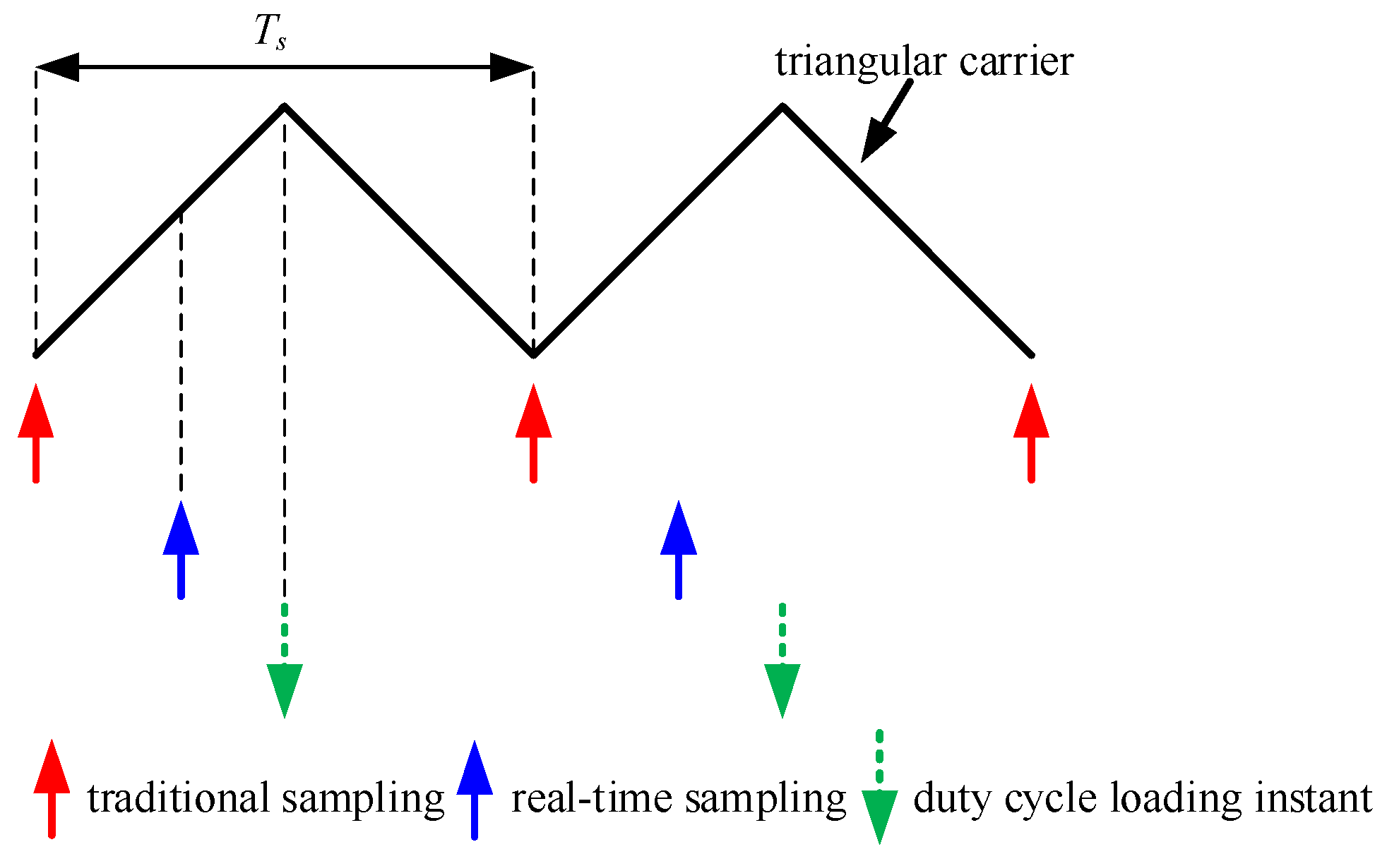
2.1. Aliasing in Digitally Controlled Inverters

The control structure diagram of the three-phase, three-wire grid-connected inverter is shown in Figure 1. The DC power is converted into AC power through the inverter, and then the AC power is transmitted to the grid through the LCL filter. The control system of the inverter consists of a bus voltage loop, a current loop, harmonic detection and control, and a phase-locked loop (PLL).
Here, the bus voltage control loop ensures that the DC bus voltage is stable. In the process of harmonic detection and control, the controlled harmonic components in the grid current are extracted by the coordinate transformation method. Then the control results are sent into the current control loop for tracking control to suppress harmonics. The sampled grid voltage is passed through the phase-locked loop to provide the phase angle for the current control loop. A phase-locked loop is used to keep the inverter output current synchronized with the grid voltage.
For the control system, the higher the crossover frequency, the greater the effect of the delay on the phase margin. The delay reduces the anti-interference ability of the system and, in severe cases, makes the system unstable. Therefore, delays should be minimized in digital control systems. Inherent delays in digitally controlled inverters mainly include computation delays and PWM loading delays [29]. The calculation delay is the time interval from the AD sampling instant to the modulation signal loading instant. Offset sampling time is a commonly used method to reduce the calculation delay so that the sampling instant is close to the loading instant. This sampling method will no longer be the standard carrier zero-crossing sampling or periodic sampling, which is called real-time sampling, as shown in Figure 2. Although the real-time sampling method can greatly reduce the calculation delay of the system, this method causes the two sampling intervals to not be fixed, which will lead to aliasing, affect the sampling accuracy, and deteriorate the power quality. Moreover, when the multiple sampling values are averaged, the stability of the system will be affected. Thus, the significance of real-time sampling is lost.

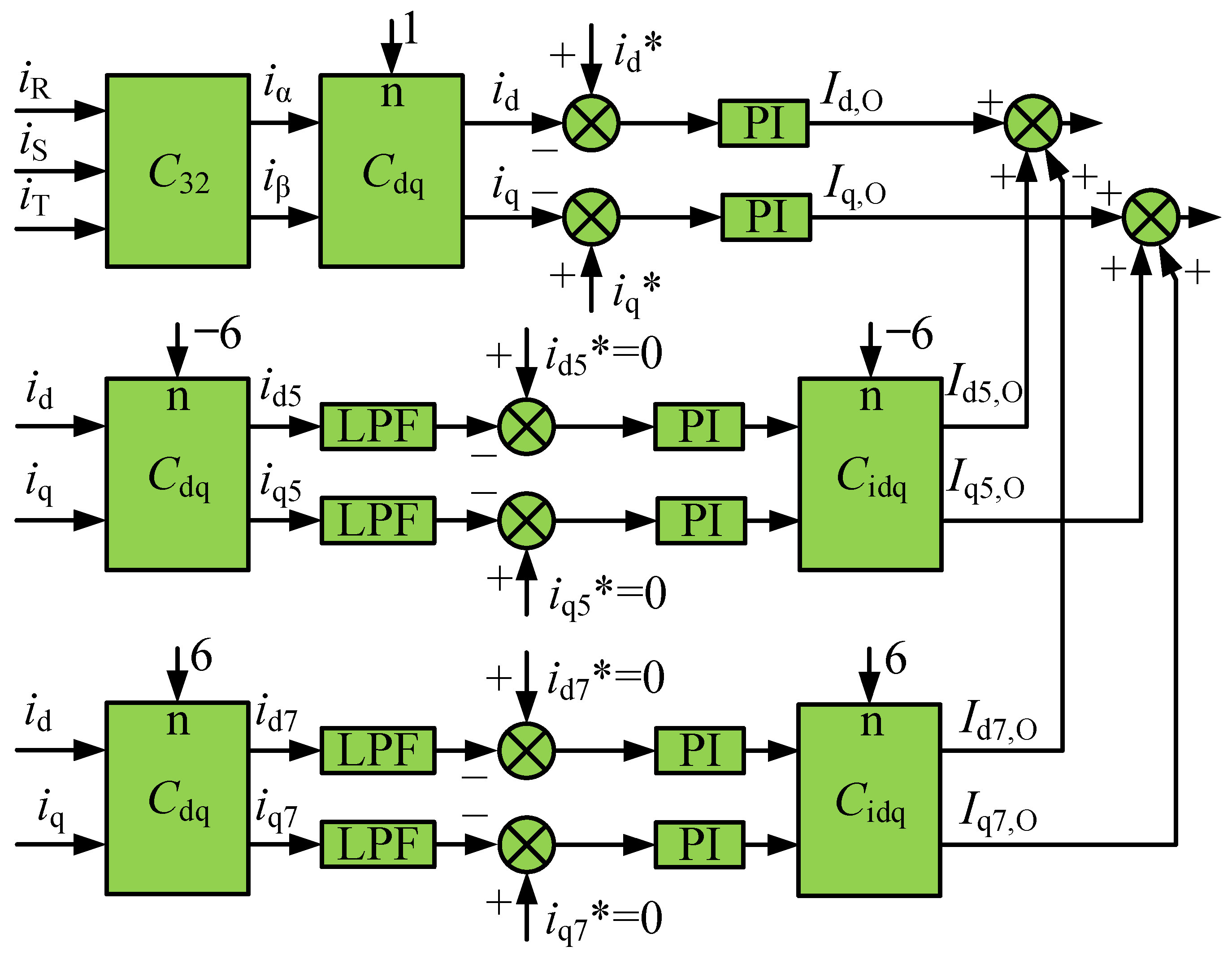
2.2. Selective Harmonic Detection and Control

The extraction of the selective harmonic component adopts the methods of fractional detection and fractional compensation. In order to improve the steady-state and dynamic performance of the control system, separated low-order harmonic current is both transformed into DC components by respective multiple synchronous reference frames (MSRF) [30], which are controlled by proportion-integral (PI) regulators in order to implement zero steady-state error compensation. Based on the above method, the n-th harmonic can be extracted through the n-th synchronous reference frame (SRF).
In a three-phase, three-wire power system, the grid current usually contains various harmonic currents. Therefore, the three-phase currents with harmonics can be expressed as follows:
{ I R ( t ) = n = 1 I n cos ( n ω t + ϕ n ) I S ( t ) = n = 1 I n cos ( n ω t 2 π 3 + ϕ n ) I T ( t ) = n = 1 I n cos ( n ω t 4 π 3 + ϕ n ) .
The current is rotated to the stationary d-q coordinate system, and the following expression is obtained:
[ i d i q ] = C dq × [ i α i β ] .
Here, the selective expressions of each parameter are as follows:
[ i α i β ] = C 32 × [ I R I S I T ] ,
C 32 = 2 3 [ 1 1 2 1 2 0 3 2 3 2 ] ,
C dq = [ cos k ω t sin k ω t sin k ω t cos k ω t ] .
In Equation (5), k is an integer other than 0. For the three-phase system, the harmonic components with high content mainly include the 5th and 7th harmonics, and the harmonics above the 7th order are relatively small and are not considered. Therefore, when k = 1, the fundamental signal can be obtained:
[ i d i q ] = [ I 1 cos ( ϕ 1 ) + I 6 cos ( 6 ω t + ϕ 6 ) I 1 sin ( ϕ 1 ) + I 6 sin ( 6 ω t + ϕ 6 ) ] .
It can be known from Equation (6) that the main components in the expressions of id and iq are the DC component and the 6-fold frequency component, of which the 6-fold frequency component is the harmonic component. It can be known from Equation (6) that the main components in the expressions of id and iq are the DC component and the 6-fold frequency component, of which the 6-fold frequency component is the harmonic component. Therefore, it is considered to adopt a nested coordinate system based on Formula (6). The coordinate systems of the two controllers are rotated by −6ω and 6ω, respectively, corresponding to the 5th negative sequence component and the 7th positive sequence component. Thus, single-harmonic extraction is achieved.
The extraction and control block diagram of a single harmonic is shown in Figure 3. The collected three-phase current is transformed into the two-phase rotating coordinate system through Formula (3) to obtain the iα and iβ components. Then iα and iβ are transformed to the d-q coordinate system by Formula (2) to obtain the id and iq components of the selective harmonics. The id and iq components are rotated at −6ω and 6ω, respectively, to obtain the DC components of the 6th wave with different phase sequences. Because this DC component has ripples, a low-pass filter (LPF) is used to filter out high-frequency components. Finally, the data after the PI regulator and Cidq inverse transformation is sent to the corresponding control loop.
Among them, the frequency domain form of the PI controller is as follows:
H PI ( s ) = K p + K i s .
Here, Kp and Ki are the proportional coefficient and integral coefficient of the PI controller of the selective harmonic in the rotating coordinate system.
The cutoff frequency of the LPF is set to 10 Hz. Therefore, the expression of the transfer function of the LPF can be written as follows:
H LPF ( s ) = ω c s + ω c .

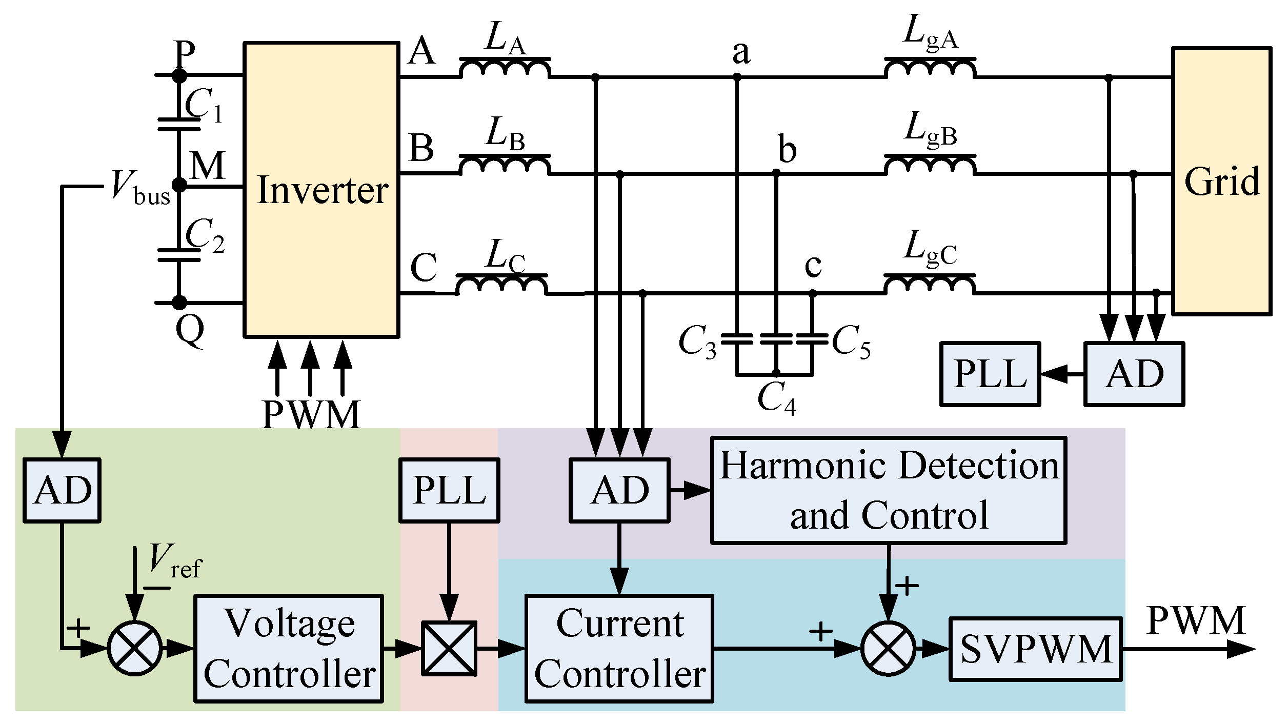
3. Proposed Harmonic and Aliasing Suppression Method

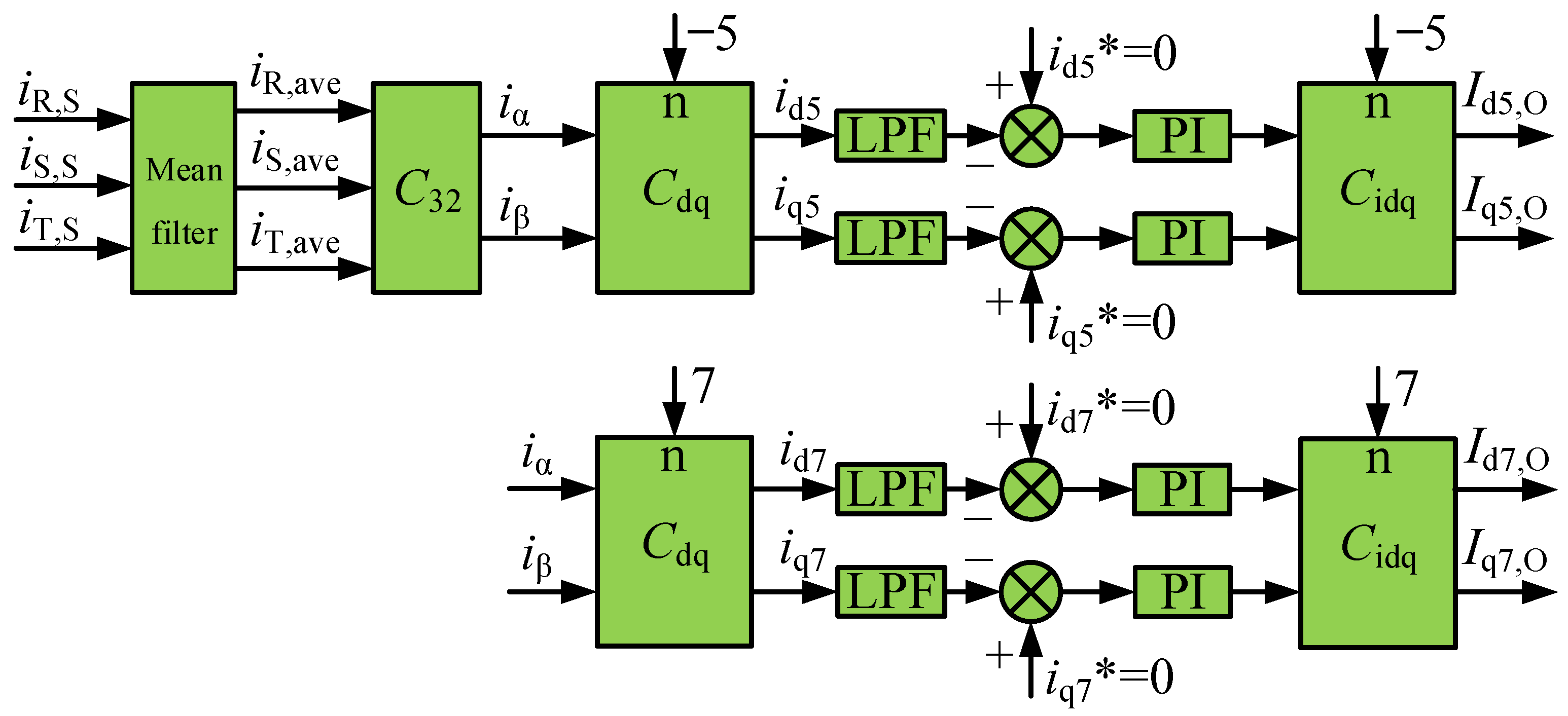
3.1. Reconstruction of the Control Algorithm Based on Multi-Sampling and Mean Filtering

According to the Shannon sampling theorem [31], when the sampling frequency is less than the Nyquist frequency, the aliasing phenomenon will be inevitable in the sampling process. As can be seen from Section 2, when the switching frequency and the sampling frequency are both equal to 16 kHz, the sampling method is called real-time sampling. However, due to factors such as interrupt loading method, sampling signal timing, switching noise, and non-linearity of reactance, real-time sampling will cause signal aliasing, which affects low-frequency sampling signals and deteriorates low-order harmonic suppression. Therefore, the above control method fails to control the single harmonic.
The multi-sampling technique is used to sample the high signal to obtain all the sampled data. The high-frequency components are then filtered out by mean filtering [32]. In this article, the sampling frequency of 128 kHz is used to sample the signal, and the sampling instantaneous value of each switching cycle can be obtained:
I j , S ( s ) = I real × e - k T s s .
where k is an even number greater than 0, Ts is the switching period, Ireal is the sampling instantaneous value, and j is R, S, or T.
Then average multiple instantaneous values sampled by each interrupt to implement mean filtering, and the following can be obtained:
I j , ave ( s ) = n = 0 k ( I real × e k T s s ) 8 .
In order to analyze the influence of different multi-sampling values on the system, the transfer functions based on multi-sampling under different conditions are obtained when k is 4, 8, and 16, respectively. The Bode diagram of Formula (10) as shown in Figure 4 can be obtained when k is 4, 8, and 16, respectively. From the amplitude-frequency characteristics of Bode, it can be known that:
  • Multi-sampling has a large attenuation ability for high-order harmonics, especially the switching frequency harmonics and their multiplier harmonics. Therefore, the influence of high-frequency components, switching frequency harmonics, and multiplied signals on sampling can be better avoided.
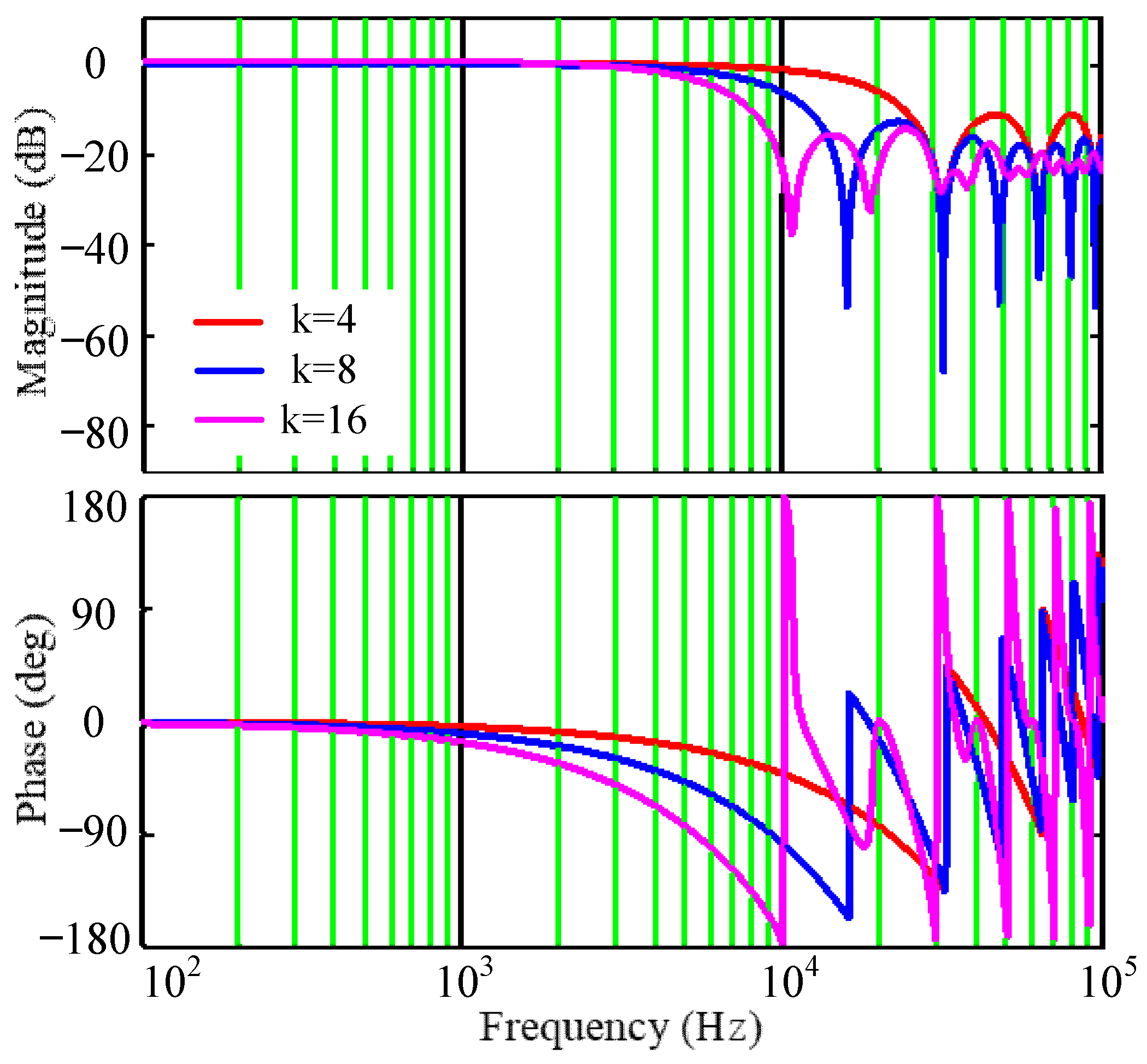
  • The more times of multi-sampling, the lower the cutoff frequency of the filter.
  • The greater the number of multi-sampling, the greater the delay of the system at half the switching frequency.
Combined with the Bode diagram shown in Figure 4, in order to filter out switching frequency harmonics as much as possible and avoid excessive multi-sampling occupying system resources, k is taken as 8. And subsequent simulations and experiments are based on this value.
In this article, the switching frequency is 16 kHz, and the crossover frequency is one tenth of the switching frequency. It can be seen from the phase-frequency characteristics in Figure 4 that the phase angle has a large lag near the crossover frequency due to the mean filter, which reduces the low phase margin of the system and affects the dynamic performance and stability of the grid-connected current. Therefore, it is not appropriate to use the average value for the inner current loop control, and the entire control system needs to be reconstructed.
A new method based on multi-sampling and mean filtering is reconstructed by independently controlling the fundamental current and the harmonic current in inner loop control. The control block diagram of harmonic control is shown in Figure 5. The selective harmonics are sampled based on the multi-sampling technique, and the sampled harmonic currents are averaged. Finally, an independent coordinate system is used to extract the selective harmonic, while the inner current loop control uses the previous sampling signal and control method, which remains unchanged.

3.2. Comparison of Different Harmonic and Aliasing Suppression Methods

Since the fundamental current control loop takes real-time samples and has no additional filters, the control delay is almost equal to zero. Table 1 gives a brief comparison of the different aliasing suppression methods. A large control delay time can degrade the steady and dynamic performance of the system, while the control delay in [16] is related to the duty ratio and the multisampling factor k (the ratio between the sampling frequency and switching frequency). The control delay will increase when the absolute value of the effective duty ratio is greater than 0.875, which will decrease the stability margin [16]. The proposed control method and the method proposed in [25] have almost no delay, while other methods inevitably introduce delay. However, the method proposed in [25] has the highest computational complexity compared with other harmonic and aliasing suppression methods and cannot filter out all switching harmonics (SHs). On the other hand, the improved repetitive filter in [23] reduces the advantage of multiple sampling and only removes integer switching harmonics, resulting in the presence of low-frequency harmonics in the control loop. However, the proposed method in this paper can filter out all switching harmonics. Therefore, the analyses show that the proposed method can not only effectively filter out high-frequency harmonics and avoid aliasing but also does not introduce control delays to affect system stability.

4. Simulation Results

In order to verify the abnormal sampling of low-order harmonics caused by sampling aliasing and to verify the proposed reconstruction algorithm based on multi-sampling and mean filtering, this article performs simulation verification on signal extraction based on the MATLAB/Simulink environment. The input signal consists of a fundamental wave with a peak value of 1 and a triangular wave with a frequency of 16 kHz, and the triangular wave component is 10%. The proposed algorithm is verified by different sampling methods.

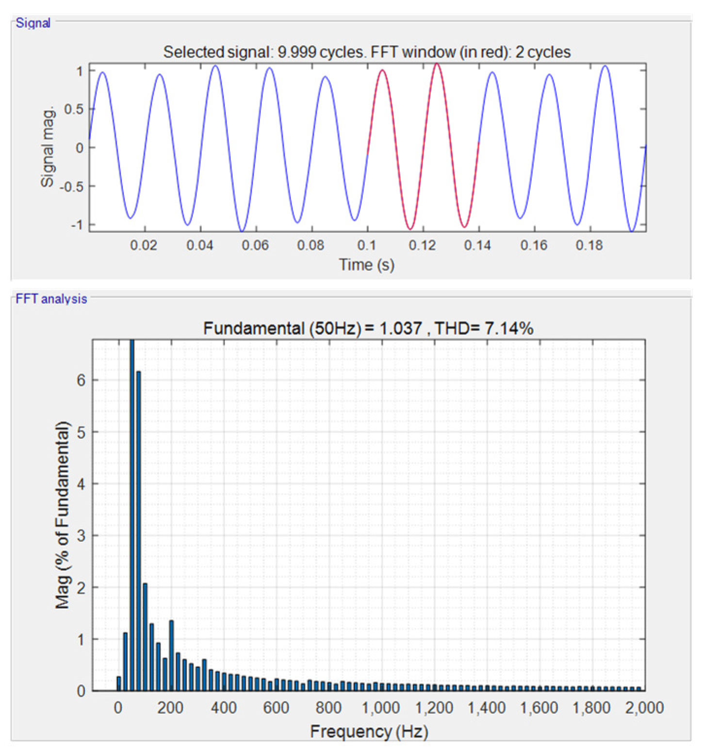
4.1. Simulation Based on Real-Time Sampling

Since the interrupt loading is affected by the content of the interrupt calculation, other interrupts, and the interference of hardware sampling, real-time sampling will cause the time interval of the two sampling periods to be inconsistent. Here, the simulation experiments are carried out with variable sampling frequencies, and sampling is performed at sampling frequencies of 15.87 kHz, 16 kHz, and 16.13 kHz by switching sampling frequencies. Figure 6 is the fast Fourier transform (FFT) analysis result of data obtained by switching sampling frequencies.
From the above simulation results, real-time sampling will cause low-frequency aliasing to affect the sampling of low-frequency harmonics, which in turn affects the control of low-frequency harmonics. There are more low-order harmonic components in the sampling results, of which the 5th harmonic component is 0.6% and the 7th harmonic component is 0.41%.

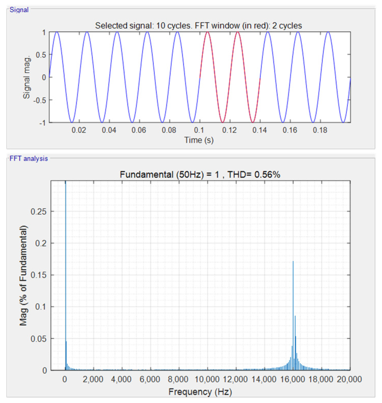
4.2. Simulation Based on Multi-Sampling and Mean Filtering

Figure 7 shows the fast Fourier transform analysis results of data obtained by switching the sampling frequency at sampling frequencies of 126.96 kHz, 128 kHz, and 129.04 kHz. It can be seen from the simulation results that the low-order harmonic components in the sampling results are almost 0, the 5th harmonic component and the 7th harmonic component are both less than 0.01%, and the 16 kHz harmonic component is attenuated from 10% to less than 0.2%. Therefore, the closed-loop control algorithm based on this sampling method can theoretically completely attenuate the low-order harmonics to zero. Moreover, the sampling data obtained based on the above reconstruction algorithm will neither affect the sampling of the low-frequency signal nor the control of the low-frequency signal.

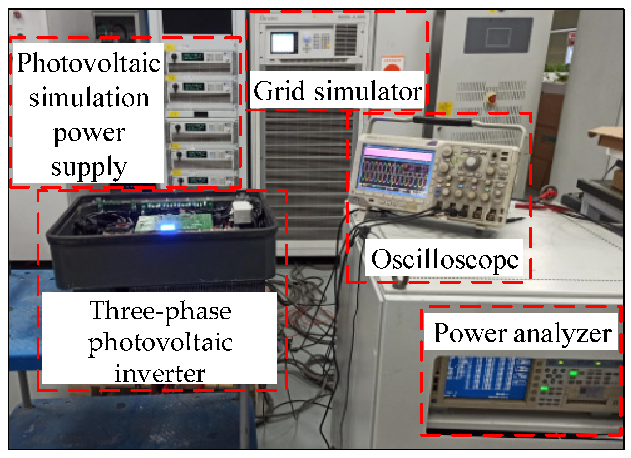
5. Experimental Verification

In order to verify the correctness of the proposed algorithm and the feasibility of the scheme, an experimental prototype of a three-phase grid-connected photovoltaic inverter with a rated power of 40 kW is built and tested, as depicted in Figure 8. A Chroma programmable regenerative grid simulator of model no. 61860 is used to simulate the power grid. Six Chroma programmable photovoltaic simulation power supplies of model no. 62180H-1800S are used to simulate the photovoltaic array input. Experimental results are obtained from an experimental prototype with the detailed parameters as shown in Table 2.

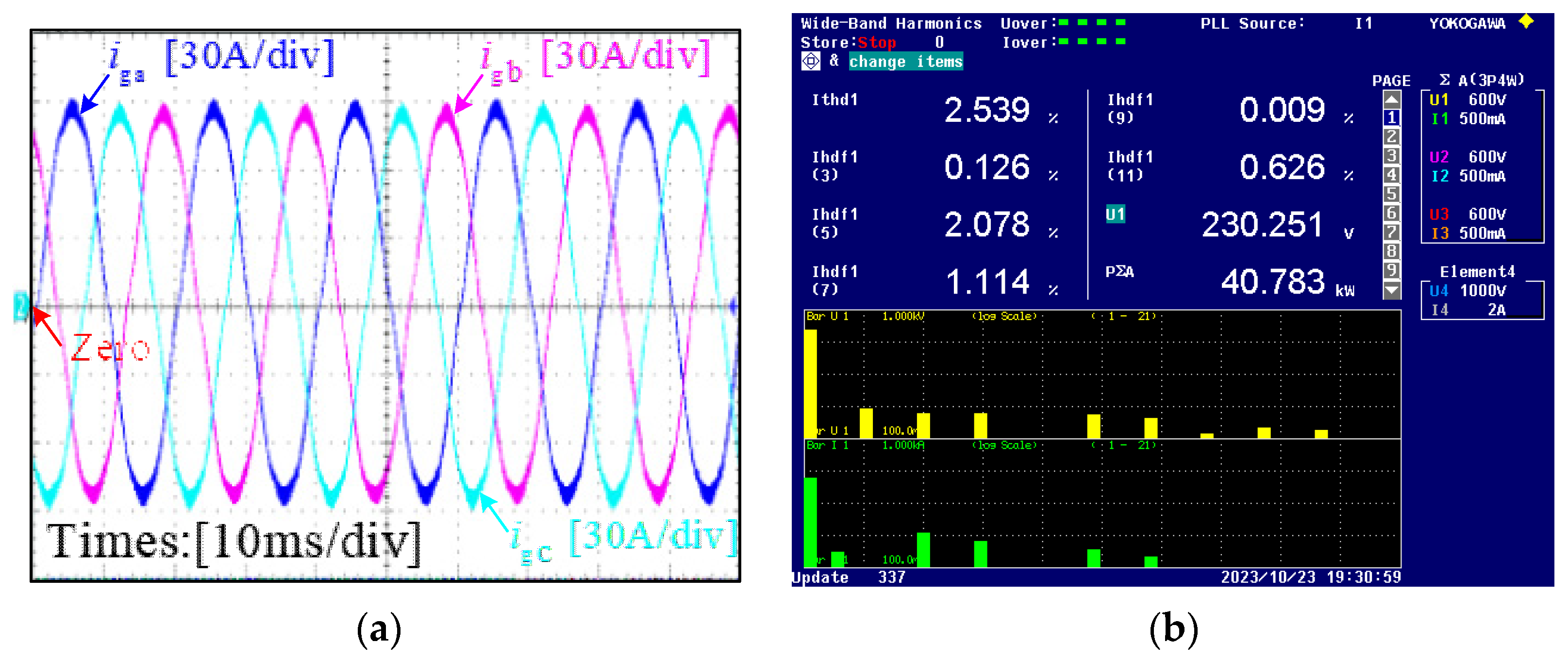
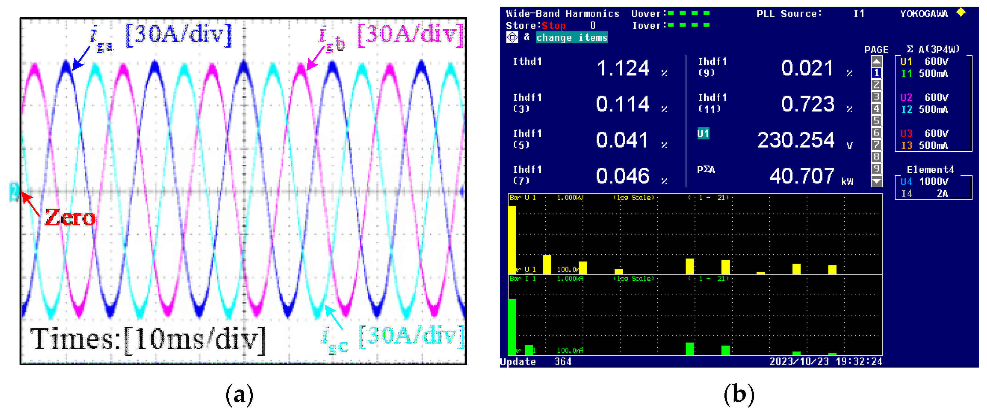
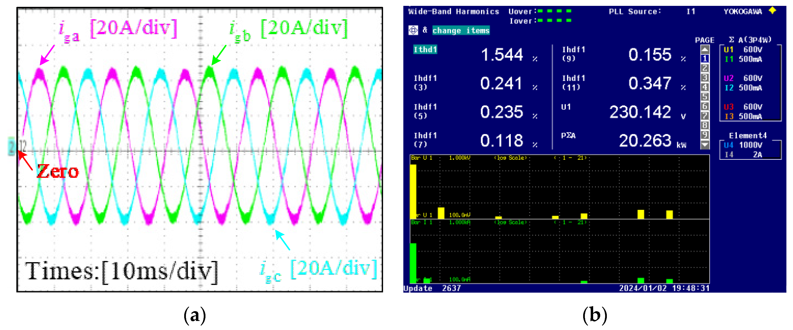
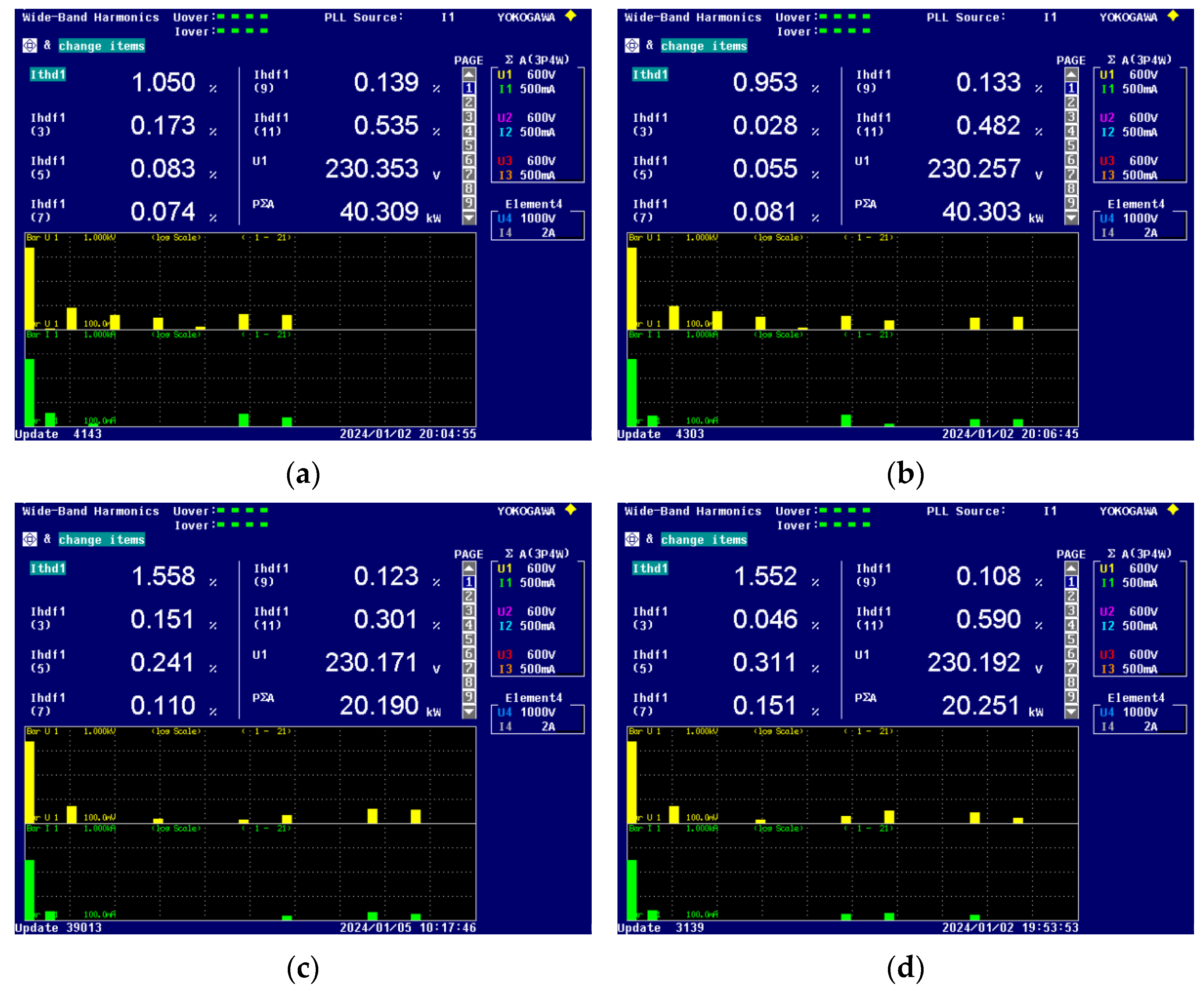
5.1. Experimental Results under Different Operating Conditions

Figure 9 shows the experimental results for 100% rated power without applying the harmonic suppression method. Figure 9a is the output current waveform, and Figure 9b is the FFT analysis result of the output current obtained by the WT3000 power analyzer. It can be seen from Figure 9 that the 5th harmonic component, the 7th harmonic component, and the total harmonic distortion without the harmonic suppression method are 2.078%, 1.114%, and 2.539%, respectively.
Figure 10 shows the experimental results for 100% rated power with the reconstruction algorithm. Figure 10a is the output current waveform. Figure 10b is the FFT analysis result of the output current obtained by the WT3000 power analyzer. It can be seen from the experimental results shown in Figure 10 that the reconstructed control algorithm can attenuate the 5th harmonic component to 0.041%, the 7th harmonic component to 0.046%, and the total harmonic distortion of the grid-connected current to 1.124%.
Figure 11 shows the experimental results for 50% rated power without the harmonic suppression method. Figure 11a is the output current waveform, and Figure 11b is the FFT analysis result of the output current obtained by the WT3000 power analyzer. It can be seen from Figure 11 that the 5th harmonic component, the 7th harmonic component, and the total harmonic distortion without the harmonic suppression method are 2.091%, 1.098%, and 2.857%, respectively.
Figure 12 shows the experimental results for 50% rated power with the reconstruction algorithm. It can be seen from the experimental results shown in Figure 12 that the reconstructed control algorithm can attenuate the 5th harmonic component to 0.235%, the 7th harmonic component to 0.118%, and the total harmonic distortion of the grid-connected current to 1.544%. From Figure 11 and Figure 12, it can be seen that the proposed control method, can also effectively reduce the 5th and 7th harmonics and the total harmonic distortion at 50% rated power.

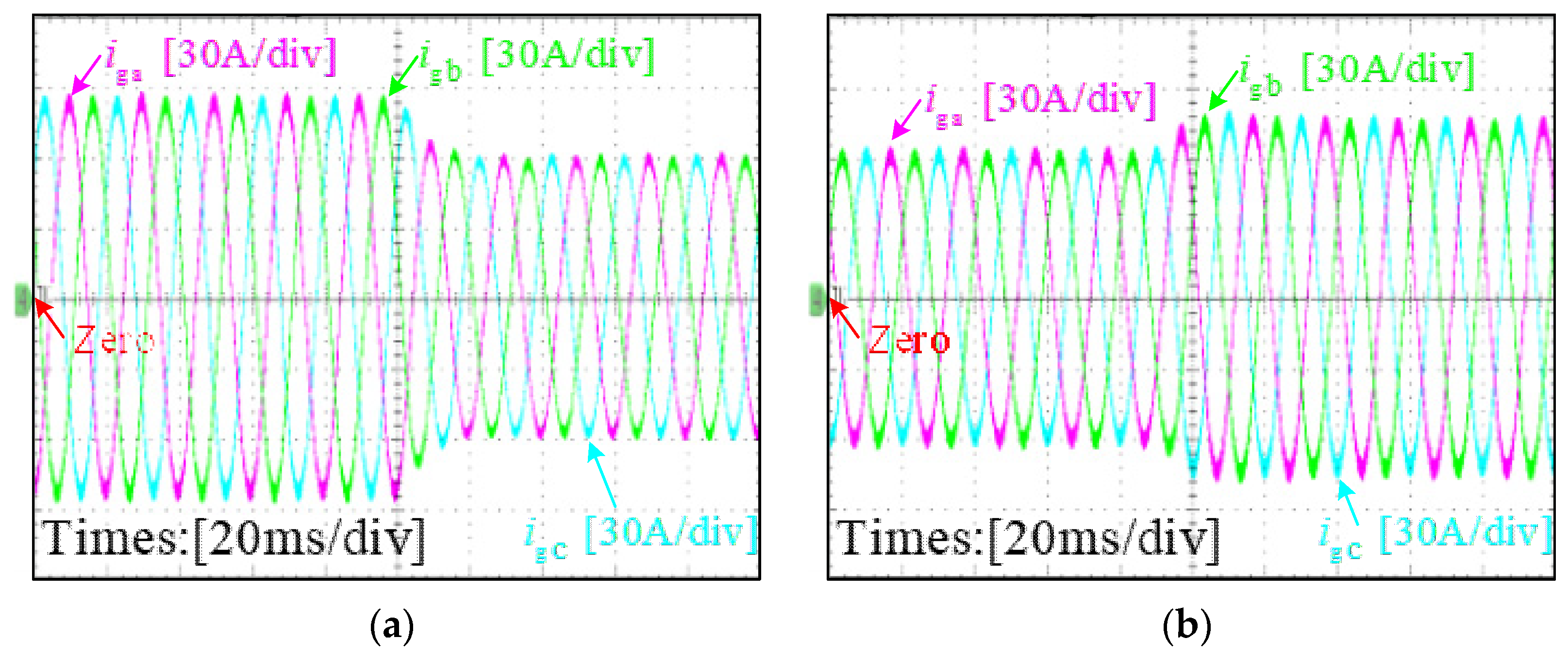
5.2. Experimental Results of Dynamic Characteristics

The dynamic experiment is tested as shown in Figure 13, when the output ac power changes from 40 kW to 30 kW and 30 kW to 35 kW, respectively. According to Chinese standard GB/T 37408-2019 [33], the inverter is able to operate continuously in the grid frequency range of 48.5 Hz to 50.5 Hz. The experimental results under different output power conditions are shown in Figure 14, when the grid frequency is abruptly changed from 50 Hz to 49 Hz and 50.5 Hz. From Figure 13 and Figure 14, it can be seen that the proposed control method has good dynamic performance.
Therefore, it can be seen from Figure 9, Figure 10, Figure 11 and Figure 12 that the 5th and 7th harmonics are effectively suppressed, and the total harmonic distortion of the output current is greatly reduced. The experimental results show that the proposed method in this article can greatly suppress the selective harmonics and reduce the total harmonic distortion. On the other hand, it can be seen from Figure 13 and Figure 14 that the proposed method has good dynamic performance under the conditions of output power perturbation and grid frequency perturbation. The experimental results are consistent with the simulation results, which verifies the correctness of the proposed sampling scheme and control strategy.

5.3. Comparison of THD for Different Harmonic Suppression Methods

The performance of different harmonic suppression methods is shown in Table 3 at rated power. Some harmonic suppression methods are provided in [7,8,9,10,11,12,13], especially in [8,10], but the ability of aliasing suppression is not analyzed. The total harmonic distortion (THD), 5th harmonic, and 7th harmonic can be reduced by less than 0.1% by the harmonic and aliasing suppression method in [18], while the method has not been further experimentally verified. Both the proposed method in this paper and the method in [26] are able to reduce the 5th and 7th harmonics to less than 0.1%, and the proposed method in this paper has a lower THD. Therefore, the proposed method in this paper has better harmonic suppression capability.

6. Conclusions

This paper presents the control structure of a three-phase grid-connected photovoltaic inverter and sampling and aliasing in a digital control system. The traditional harmonic current frequency dividing control strategy for a three-phase grid-connected photovoltaic inverter based on multiple synchronous reference frames is derived. Then, an improved harmonic suppression method based on multisampling and mean filtering and a new harmonic detection and control method are proposed. The proposed control method achieves accurate sampling and control of the fundamental and harmonic currents by sampling and controlling the fundamental and harmonic currents independently, so that aliasing is not introduced into the control loop. Therefore, the control delay, the total harmonic distortion, and the low odd harmonic content are effectively reduced under the premise of guaranteeing the stability of the system.
Another contribution of this paper is that MATLAB/Simulink-based simulations and experiments verify that real-time sampling introduces aliasing in the control loop, resulting in an increase in the total harmonic distortion and low-order odd harmonic content. The proposed control method can almost reduce the selective low-order harmonic content to zero at rated power. First, the experimental results have shown that the proposed method can effectively suppress the selective low-order current harmonics, such as the 5th and 7th harmonics. The experimental results are consistent with the simulation results, which verifies the correctness of the proposed sampling scheme and control strategy. Therefore, the scheme can also be applied to the suppression of other harmonics, such as the 11th and 13th harmonics, with high practicality. Secondly, the experimental results have shown that the proposed method has good dynamic performance under the conditions of output power perturbation and grid frequency perturbation. On the other hand, the comparative analysis reveals that the proposed method has some advantages in harmonic and aliasing suppression and control delay. In conclusion, experimental results have shown the good harmonic suppression and anti-aliasing effects of the proposed method and the improvement of control performance.

Author Contributions

H.G., Y.X. and W.W. contributed to conceptualization and design of the study; methodology, H.G.; software, Y.X.; validation, H.G., Y.X. and W.W.; formal analysis, H.G.; investigation, Y.X.; resources, H.G.; data curation, Y.X.; writing—original draft preparation, H.G.; writing—review and editing, Y.X. and W.W.; visualization, H.G.; supervision, W.W.; project administration, W.W.; funding acquisition, H.G., Y.X. and W.W. All authors have read and agreed to the published version of the manuscript.

Funding

National Natural Science Foundation of China under Grant 52177186.

Data Availability Statement

Data are contained within the article.

Acknowledgments

This work was supported in part by the National Natural Science Foundation of China under Grant 52177186 and also in part by the Shanghai Frontiers Science Center of “Full Penetration” Far-Reaching Offshore Ocean Energy and Power.

Conflicts of Interest

The author declares no conflict of interest.

References

  1. de Jesus, V.M.R.; Cupertino, A.F.; Xavier, L.S.; Pereira, H.A.; Mendes, V.F. Operation Limits of Grid-Tied Photovoltaic Inverters with Harmonic Current Compensation Based on Capability Curves. IEEE Trans. Energy Convers. 2021, 36, 2088–2098. [Google Scholar] [CrossRef]
  2. Elhassan, G.; Zulkifli, S.A.; Iliya, S.Z.; Bevrani, H.; Kabir, M.; Jackson, R.; Khan, M.H.; Ahmed, M. Deadbeat Current Control in Grid-Connected Inverters: A Comprehensive Discussion. IEEE Access 2022, 10, 3990–4014. [Google Scholar] [CrossRef]
  3. Zhang, B.; Zhou, K.; Wang, D. Multirate Repetitive Control for PWM DC/AC Converters. IEEE Trans. Ind. Electron. 2014, 61, 2883–2890. [Google Scholar] [CrossRef]
  4. Choi, W.; Lee, W.; Han, D.; Sarlioglu, B. New Configuration of Multifunctional Grid-Connected Inverter to Improve Both Current-Based and Voltage-Based Power Quality. IEEE Trans. Ind. Appl. 2018, 54, 6374–6382. [Google Scholar] [CrossRef]
  5. Awal, M.A.; Flora, L.D.; Husain, I. Observer Based Generalized Active Damping for Voltage Source Converters with LCL Filters. IEEE Trans. Power Electron. 2022, 37, 125–136. [Google Scholar] [CrossRef]
  6. Liu, G.; Mattavelli, P. Hysteresis Droop Controller with One Sample Delay for DC-DC Converters in DC Microgrids. In Proceedings of the 2019 IEEE Energy Conversion Congress and Exposition (ECCE), Baltimore, MD, USA, 29 September–3 October 2019. [Google Scholar]
  7. Liu, Y.; Li, L.; Shan, P.; Yu, H.; Zhang, S.; Huang, M.; Liu, W.; You, X.; Zhang, P.; Sun, Y.; et al. Coordinated Mitigation Control for Wideband Harmonic of the Photovoltaic Grid-Connected Inverter. Appl. Sci. 2023, 13, 7441. [Google Scholar] [CrossRef]
  8. Li, S.; Zhou, S.; Li, H. Harmonic Suppression Strategy of LCL Grid-Connected PV Inverter Based on Adaptive QPR_PC Control. Electronics 2023, 12, 2282. [Google Scholar] [CrossRef]
  9. He, G.; Lin, J.; Li, G.; Dong, Y.; Zhang, W. DC Component Suppression of Grid-Connected Z-Source Inverter Based on Disturbance Observer. Energies 2022, 15, 5700. [Google Scholar] [CrossRef]
  10. Yan, H.; Cai, H. Research on Fuzzy Active Disturbance Rejection Control of LCL Grid-Connected Inverter Based on Passivity-Based Control in Weak Grid. Electronics 2023, 12, 1847. [Google Scholar] [CrossRef]
  11. He, G.; Chen, G.; Dong, Y.; Li, G.; Zhang, W. Research on LADRC of Grid-Connected Inverter Based on LCCL. Energies 2022, 15, 4686. [Google Scholar] [CrossRef]
  12. Zhang, B.; Wu, W.; Yang, Y.; Gao, N.; Chen, J.; Koutroulis, E.G.; Chung, H.S.-H.; Liserre, M.; Blaabjerg, F. A Novel Simplified Finite Control Set Repeat Model Predictive Control for Grid-Connected Inverters. IEEE Trans. Ind. Electron. 2023, 70, 11324–11333. [Google Scholar] [CrossRef]
  13. Chen, X.; Wu, W.; Gao, N.; Chung, H.S.-H.; Liserre, M.; Blaabjerg, F. Finite Control Set Model Predictive Control for LCL-Filtered Grid-Tied Inverter with Minimum Sensors. IEEE Trans. Ind. Electron. 2020, 67, 9980–9990. [Google Scholar] [CrossRef]
  14. Wang, C.; Zhang, L.; Xie, W.; Xiao, L.; Zhang, Z.; Zhang, Z.; Chen, D. Analysis and Suppression of the Frequency-Aliasing Phenomenon Related to the Sorting-Algorithm-Based Voltage-Balance Strategy in an MMC System. IEEE Trans. Power Electron. 2022, 37, 170–182. [Google Scholar] [CrossRef]
  15. Zhang, B.; Xu, J.; Xie, S. Analysis and suppression of the aliasing in real-time sampling for grid-connected LCL-filtered inverters. In Proceedings of the 2016 IEEE 11th Conference on Industrial Electronics and Applications (ICIEA), Hefei, China, 5–7 June 2016; pp. 304–309. [Google Scholar]
  16. Zou, C.; Liu, B.; Duan, S.; Li, R. Influence of Delay on System Stability and Delay Optimization of Grid-Connected Inverters with LCL Filter. IEEE Trans. Ind. Inform. 2014, 10, 1775–1784. [Google Scholar] [CrossRef]
  17. Pan, D.; Ruan, X.; Bao, C.; Li, W.; Wang, X. Capacitor-Current-Feedback Active Damping with Reduced Computation Delay for Improving Robustness of LCL-Type Grid-Connected Inverter. IEEE Trans. Power Electron. 2014, 29, 3414–3427. [Google Scholar] [CrossRef]
  18. He, S.; Zhou, D.; Wang, X.; Blaabjerg, F. Switching Harmonics Suppression of Single-loop Multi-sampling Control of Grid-connected Inverter. In Proceedings of the IECON 2020 the 46th Annual Conference of the IEEE Industrial Electronics Society, Singapore, 18–21 October 2020; pp. 3259–3264. [Google Scholar]
  19. Li, R.; Liu, B.; Duan, S.; Zou, C.; Jiang, L. Analysis and Suppression of Alias in Digitally Controlled Inverters. IEEE Trans. Ind. Inform. 2014, 10, 655–665. [Google Scholar] [CrossRef]
  20. Amin, A.M.A.; El-Korfolly, M.I.; Mohammed, S.A. Exploring aliasing distortion effects on regularly-sampled PWM signals. In Proceedings of the 2008 3rd IEEE Conference on Industrial Electronics and Applications, Singapore, 3–5 June 2008; pp. 2036–2041. [Google Scholar]
  21. He, S.; Zhou, D.; Wang, X.; Blaabjerg, F. Overview of Multisampling Techniques in Power Electronics Converters. In Proceedings of the IECON 2019—45th Annual Conference of the IEEE Industrial Electronics Society, Lisbon, Portugal, 14–17 October 2019; pp. 1922–1927. [Google Scholar]
  22. Ma, J.; Wang, X.; Blaabjerg, F.; Song, W.; Wang, S.; Liu, T. Multisampling Method for Single-Phase Grid-Connected Cascaded H-Bridge Inverters. IEEE Trans. Ind. Electron. 2020, 67, 8322–8334. [Google Scholar] [CrossRef]
  23. Shi, Y.; Xu, J.; Xie, S. Aliasing Effect in Real-Time Sampling for Grid-Connected LCL-LC-Filtered Inverter with Capacitor Current Feedback. In Proceedings of the 2021 IEEE 12th Energy Conversion Congress & Exposition—Asia (ECCE-Asia), Singapore, 24–27 May 2021; pp. 1366–1371. [Google Scholar]
  24. Vukosavić, S.N.; Perić, L.S.; Levi, E. AC Current Controller with Error-Free Feedback Acquisition System. IEEE Trans. Energy Convers. 2016, 31, 381–391. [Google Scholar] [CrossRef]
  25. He, S.; Zhou, D.; Wang, X.; Blaabjerg, F. Aliasing Suppression of Multisampled Current-Controlled LCL-Filtered Inverters. IEEE J. Emerg. Sel. Top. Power Electron. 2022, 10, 2411–2423. [Google Scholar] [CrossRef]
  26. Ma, C.; Duan, Q.; Sheng, W.; Li, Y.; Wang, H. High-Frequency Current Ripple Sample Anti-Aliasing Strategy of Digitally Controlled Converter Based on Notch Filter. IEEE Access 2023, 11, 16757–16767. [Google Scholar] [CrossRef]
  27. Wang, T.; Yao, W.; Li, C.; Yang, H.; Li, W. Aliasing Suppression with Negligible Phase Lag for Multi-Sampled LCL-Type Grid-Tied Inverter. IEEE Trans. Power Electron. 2023, 38, 12520–12535. [Google Scholar] [CrossRef]
  28. Castelló, J.; Espí, J.M.; García-Gil, R. A New Generalized Robust Predictive Current Control for Grid-Connected Inverters Compensates Anti-Aliasing Filters Delay. IEEE Trans. Ind. Electron. 2016, 63, 4485–4494. [Google Scholar] [CrossRef]
  29. Wang, T.; Yao, W.; Yang, H.; Li, W.; Ou, Z. Dissipativity Enhancement for Multisampled LCL-Type Inverter Using a Low-Delay Ripple-Removal Method. IEEE J. Emerg. Sel. Top. Power Electron. 2023, 11, 4784–4798. [Google Scholar] [CrossRef]
  30. Yan, L.C.; Zhu, Z.Q.; Qi, J.; Ren, Y.; Gan, C.; Brockway, S.; Hilton, C. Multiple Synchronous Reference Frame Current Harmonic Regulation of Dual Three Phase PMSM with Enhanced Dynamic Performance and System Stability. IEEE Trans. Ind. Electron. 2022, 69, 8825–8838. [Google Scholar] [CrossRef]
  31. Petric, I.Z.; Mattavelli, P.; Buso, S. Feedback Noise Propagation in Multisampled DC–DC Power Electronic Converters. IEEE Trans. Power Electron. 2022, 37, 150–161. [Google Scholar] [CrossRef]
  32. Zmood, D.N.; Holmes, D.G.; Bode, G.H. Frequency-domain analysis of three-phase linear current regulators. IEEE Trans. Ind. Appl. 2001, 37, 601–610. [Google Scholar] [CrossRef]
  33. Technical Requirements for Photoltaic Grid-Connected Inverter; China Electric Power Press: Beijing, China, 2019.
Figure 1. Control block diagram of LCL-filtered grid-connected inverter.
Energies 17 00907 g001
Figure 2. Sampling and loading of a digitally controlled inverter.
Energies 17 00907 g002
Figure 3. Traditional 5th and 7th harmonic detection methods and control block diagram.
Energies 17 00907 g003
Figure 4. Bode diagram of the transfer function based on multi-sampling and mean filtering.
Energies 17 00907 g004
Figure 5. The proposed control block diagram of the 5th and 7th harmonics.
Energies 17 00907 g005
Figure 6. FFT analysis result of data obtained by switching sampling frequency based on real-time sampling.
Energies 17 00907 g006
Figure 7. FFT analysis result of data obtained by switching sampling frequency based on the proposed method.
Energies 17 00907 g007
Figure 8. Experimental prototype.
Energies 17 00907 g008
Figure 9. The experimental results for 100% rated power without the harmonic suppression algorithm: (a) grid-connected current waveform; (b) the FFT analysis result of the output current.
Energies 17 00907 g009
Figure 10. The experimental results for 100% rated power with the proposed harmonic suppression algorithm: (a) grid-connected current waveform; (b) the FFT analysis result of the output current.
Energies 17 00907 g010
Figure 11. The experimental results for 50% rated power without the harmonic suppression algorithm: (a) grid-connected current waveform; (b) the FFT analysis result of the output current.
Energies 17 00907 g011
Figure 12. The experimental results for 50% rated power with the proposed harmonic suppression algorithm: (a) grid-connected current waveform; (b) the FFT analysis result of the output current.
Energies 17 00907 g012
Figure 13. Measured grid-injected current of the proposed system: (a) when the output ac power changes from 40 kW to 30 kW; (b) when the output ac power changes from 30 kW to 35 kW.
Energies 17 00907 g013
Figure 14. The FFT analysis results of the output current under different output power and grid frequencies: (a) 100% rated power and 49 Hz; (b) 100% rated power and 50.5 Hz; (c) 50% rated power and 49 Hz; (d) 50% rated power and 50.5 Hz.
Energies 17 00907 g014
Table 1. Comparison of different aliasing suppression methods.
MethodHarmonic SuppressionDelay TimeComplexity of the Method
Method in [18]Cannot filter out all SHsTsw/4 or Tsw/2Low
Method in [24]Can filter out all SHsTsw/2Low
Method in [25]Can cause high-frequency noise amplificationTsw/4Low
Method in [27]Can filter out all main SHs≈0High
Methods in this paperCan filter out all SHs≈0Medium
Table 2. Main parameters of a grid-connected inverter.
SymbolQuantityValue
LA/LB/LCInverter-side filter inductor185 uH
LgA/LgB/LgCGrid-side inductor12 uH
C4/C5/C6Filter capacitor8 uF
VbusDC-link voltage680 V
fcCarrier frequency16 kHz
PoRated output power40 kW
VgOutput voltage230 V
Table 3. Comparison of THD for different harmonic suppression methods.
Methods5th Harmonic7th HarmonicTHD
Method in [7]0.481%0.844%1.690%
Method in [8]<0.100%<0.100%0.940%
Method in [9]≈0.250%≈0.190%2.840%
Method in [10]<0.100%<0.100%0.510%
Method in [11]≈0.200%≈0.160%0.730%
Method in [18]<0.100%<0.100%0.090%
Method in [25]≈0.200%≈0.400%1.100%
Method in [26]<0.100%<0.100%2.230%
Method in [27]≈1.700%≈0.400%2.460%
Method in this paper0.041%0.046%1.124%
Disclaimer/Publisher’s Note: The statements, opinions and data contained in all publications are solely those of the individual author(s) and contributor(s) and not of MDPI and/or the editor(s). MDPI and/or the editor(s) disclaim responsibility for any injury to people or property resulting from any ideas, methods, instructions or products referred to in the content.

