Article

Stability Enhancement Method of Standalone Modular Multilevel Converters Based on Impedance Reshaping

1
Electric Power Research Institute, Guizhou Power Grid Co., Ltd., Guiyang 550002, China
2
College of Electrical Engineering Shanghai University of Electric Power, Shanghai 200090, China
*
Author to whom correspondence should be addressed.
Energies 2024, 17(4), 895; https://doi.org/10.3390/en17040895
Submission received: 11 January 2024 / Revised: 1 February 2024 / Accepted: 9 February 2024 / Published: 14 February 2024
(This article belongs to the Special Issue Advanced Application of Power Electronics in Power Systems)

Abstract

:
Modular multilevel converters (MMCs) are susceptible to subsynchronous oscillations (SSOs) caused by impedance interactions in the power line. Current research into the stability of MMCs focuses mainly on voltage feed-forward control, while the effect of current feed-forward control is neglected. This paper proposes a current feed-forward compensation method based on impedance reshaping for standalone MMCs. Initially, an impedance model was developed to identify the stability risks caused by the interaction between the MMC and power line impedance. The proposed method feeds the current compensation signal into the modulation circuit, thereby improving the control signal and suppressing the impedance interaction between the MMC and the power line. The analysis of the harmonic state space (HSS) method verifies that the proposed approach effectively reduces the negative damping region in the frequency band where the SSO is located. Additionally, the impedance frequency scanning method confirms the accuracy of impedance modeling. Using the MATLAB/Simulink platform and StarSim HIL hardware-in-the-loop experimental platform, the SSO phenomenon of the MMC is simulated, and the results show that the proposed method can effectively suppress harmonic currents during SSO, which verifies the accuracy of the stability analysis and the feasibility of the proposed method.

1. Introduction

Modular multilevel converters are extensively utilized in high-voltage direct current (HVDC) transmission systems owing to their modularity [1,2], extensibility [3,4], and favorable output performance [5,6,7]. Two operational modes are identified for MMC-HVDC projects: grid-connected mode and standalone mode [8,9]. In the grid-connected mode, active and reactive power control outer loops primarily govern MMC operations. Conversely, the standalone mode operations of MMC-HVDC projects are directed by controlling the AC voltage and frequency.
However, when interfacing with the impedance of the power line, MMCs tend to exhibit oscillatory behavior [10,11,12]. Recent commissions of MMC-HVDC projects have highlighted relevant stability issues. For instance, a 1500 Hz resonance was detected during AC side charging in the Zhangbei MMC-HVDC project in China [13], the Borwin2 project in Germany encountered a 451 Hz resonance during the supply of offshore wind power via MMC-HVDC [14], and a 42.5 Hz subsynchronous oscillation transpired in the Zhoushan multiterminal project in China when the operating mode transitioned from grid-connected to standalone during line maintenance shutdown [15]. The increase in the capacity and number of MMC-HVDC projects considerably increases the impact of these engineering projects on power quality. In milder scenarios, these mishaps may degrade grid power quality, while in severe instances, they may necessitate project shutdowns [16,17].
Addressing the power oscillation predicament in MMC-HVDC is critical for ensuring smooth operation and facilitating future expansions of MMC technology. An initial step toward alleviating power oscillation risks involves establishing a stability impedance model for the MMC system. Impedance modeling methodologies for MMC systems span two domains: time and frequency domain modeling. Time domain modeling primarily employs a dynamic phaser based on Park transform [18], which is applied across various frequencies to obtain the corresponding frequency components. However, the complexity of expressing Park transform increases considerably with the inclusion of high-order harmonics owing to its reliance on trigonometric functions. Frequency domain modeling predominantly encompasses multiharmonic modeling. J. Lyu proposed a novel MMC system method employing the HSS [19]. HSS methodology, which leverages Toeplitz matrices, simplifies the extension to all harmonic orders and elucidates harmonic interrelationships. Furthermore, the matrix-centric modeling approach of HSS provides a clearer expression compared with time domain modeling, facilitates computation, and renders a clear physical interpretation. Consequently, this study adopts the HSS method for impedance modeling.
Following impedance modeling, stability enhancement methods can be employed in system areas identified with oscillation risk to mitigate it. Three primary methods exist to enhance the stability of the MMC system: control parameter optimization, additional passive damping, and additional active damping [19,20,21,22,23,24,25,26]. Control parameters are optimized using an impedance stability criterion that evaluates the magnitude and phase of the MMC system and the corresponding single-input single-output system on the Bode plot to determine appropriate control parameters for oscillation mitigation. In [19,20], proportional-integral control parameters are designed based on whether the impedance of the MMC system and the wind farm adhere to the stability criterion. However, if operational environment alterations occur, the stabilization region deduced from this method may become ineffective. Additional passive damping encompasses the inclusion of extra passive devices and harmonic injection. The deployment of additional passive devices results in considerable power losses, rendering this method infrequently utilized in engineering practices [21,22]. In [23], transient harmonic injection disrupts the original in-system characteristic coupling, consequently modifying the MMC impedance damping response in the low-frequency range and destabilizing the MMC system. Additional active damping involves the introduction of a corresponding feedback relationship in the original control circuit. By adjusting the feedback, the amplitude and phase of the impedance react correspondingly, thereby altering the impedance characteristics [24,25,26,27]. In [24], a feed-forward voltage branch incorporating active damping based on the round function is discussed, which curtails overcurrent during fault scenarios, enhancing MMC operation stability. In [25], a comparison of three different orders of active feed-forward voltage damping is presented, along with the design of active damping controllers to suppress high-frequency oscillations as a function of gain and cutoff frequency. In [26], a phase compensation method was introduced in active damping control to suppress oscillations. In [27], active damping control is improved by combining a high-pass filter with a low-pass filter.
However, existing studies [24,25,26,27] have focused on active damping controllers with voltage feed-forward. Given the diverse effects of different feed-forward control loops on stability, it is crucial to explore the impact of loops beyond voltage on stability. Hence, this study investigates the effect of current feed-forward on stability enhancement. The stability of standalone operating MMC systems is investigated. The results reveal that in a closed-loop voltage scenario, the MMC system is susceptible to SSO issues. A large low-frequency harmonic current at SSO is also observed. To suppress this harmonic current, an impedance reshaping method using feed-forward current compensation is proposed, and corresponding design guidelines are given. Related experiments show that the proposed method mitigates SSOs.
The remainder of this paper is organized as follows: Section 2 reviews the modeling of MMC systems using the HSS approach. Section 3 introduces an impedance reshaping method to mitigate SSOs, accompanied by design guidelines. Section 4 provides a case study of MMC, substantiated by simulation verification. Section 5 presents the validation of the proposed strategy’s effectiveness using a hardware-in-the-loop platform. Section 6 presents the conclusions of this study.

2. An HSS-Based Approach to MMC Impedance Modeling

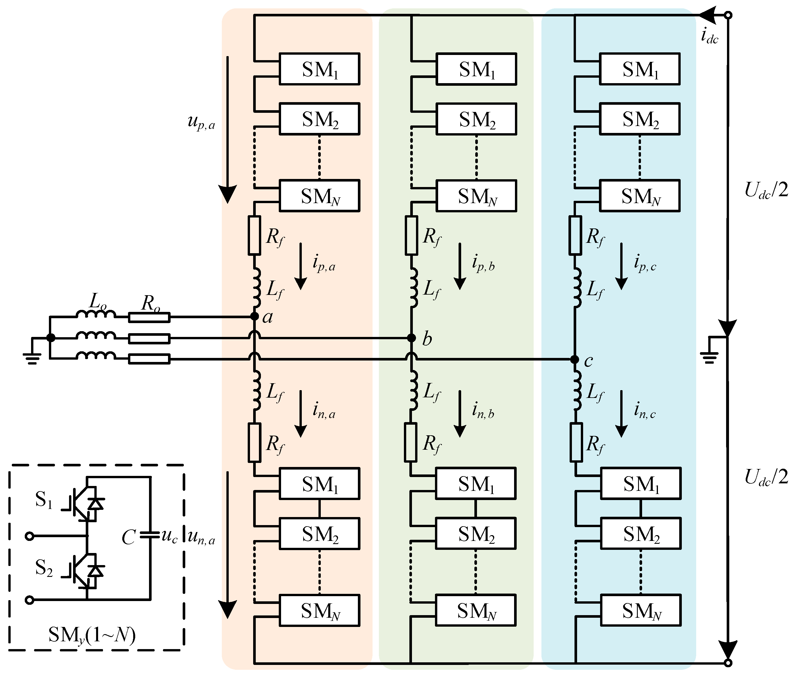
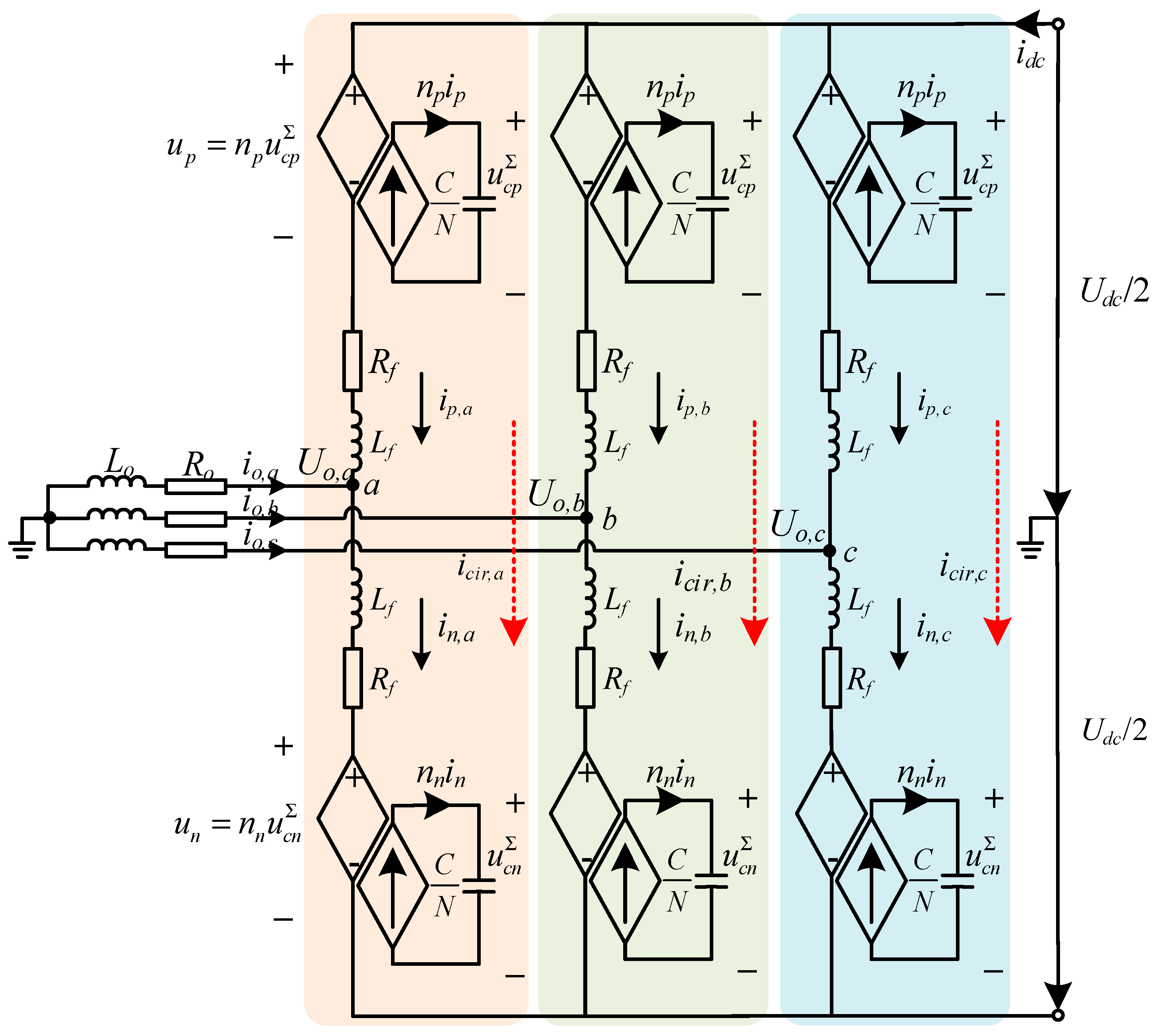
2.1. Average MMC Topology

As can be seen from Figure 1, the MMC topology consists of upper and lower arms, each of which is connected in series with N half-bridge submodules SMy(1~N), an arm resistor Rf, and an arm inductor Lf. Up,j(j = a, b, c) and Un,j(j = a, b, c) represent the voltages of the series-connected half-bridge submodules of the upper and lower arms. ip,j(j = a, b, c) and in,j(j = a, b, c) represent the currents flowing through the upper and lower arms. Udc and idc represent the voltages and currents flowing through the DC side of the MMC.
Resistor Ro and inductor Lo are used to simulate the load on the AC side of the MMC.
The number of three-phase upper and lower arm submodules for MMCs in HVDC transmission projects is often very high, making the detailed model difficult to construct. Therefore, it is essential to address the difficulty in modeling by using the average value model [28] presented in Figure 2.
For analysis purposes, define io,j(j = a, b, c) as the AC side output current with the expression io,j = in,jip,j(j = a, b, c); define icir,j (j = a, b, c) as the circulating current with the expression icir,j = (in,jip,j)/2 (j = a, b, c). Define Carm(Carm = C/N) as the equivalent submodule capacitance of N half-bridge submodules SMy(1~N) after the MMC uses the average model.
Based on the above definitions, the Kirchhoff voltage and current equations for the circuit shown in Figure 2 are established to obtain the MMC time domain model equations:
U d c 2 U o = n p u c p Σ + R f i p + L f d i p d t
U d c 2 + U o = n n u c n Σ + R f i n + L f d i n d t
where u Σ   c x (x = p, n) and nx(x = p, n) represent the cumulative value of the submodule capacitance voltages of the upper and lower arms of the MMC and the superimposed value of the submodule control signals.
The internal dynamic characteristics of the MMC after using the average value model can be expressed as follows:
d u c p Σ d t = n p C a r m i p
d u c n Σ d t = n n C a r m i n
The derivation of Equations (1) and (2) leads to the MMC equivalent differential mode circuit (DM) and common mode circuit (CM):
U Δ 2 U o = L Δ d i o d t + R Δ i o
U d c U Σ = L Σ d i c i r d t + R Σ i c i r
where UΔ = (UnUp)/2, U = (Un + Up), LΔ = Lf/2, RΔ = Rf/2, L = 2Lf, R = 2Rf.
Based on Equations (5) and (6), Figure 3 illustrates that the MMC topology’s control circuit is related to the DM and CM voltages. Therefore, the control of the MMC is equivalent to the control of DM voltage and CM voltage. The DM voltage is reflected in the output voltage Uo, and the CM voltage is reflected in the circulating current icir. Therefore, the MMC only needs to control Uo and icir to realize the stable operation of the circuit. For controlling Uo and icir, a proportional resonance controller (PR) is employed.
This paper focuses on the SSOs caused by the outer loop. Therefore, the current inner loop is not considered [29]. The transfer function of the proportional resonant controller that regulates Uo and icir is shown as:
G d m ( s ) = K P d m + 2 K R d m ω v s s 2 + 2 ω v s + ω 0 2
G c m ( s ) = K P c m + 2 K R c m ω c s s 2 + 2 ω c s + ( 2 ω 0 ) 2
where KPdm and KPcm are proportional resonance controller proportional gains, KRdm and KRcm are proportional resonance controller proportional partial resonance gains, ωv and ωc are proportional resonance controller proportional partial resonance bandwidths, and ω0 is the fundamental frequency angular frequency.

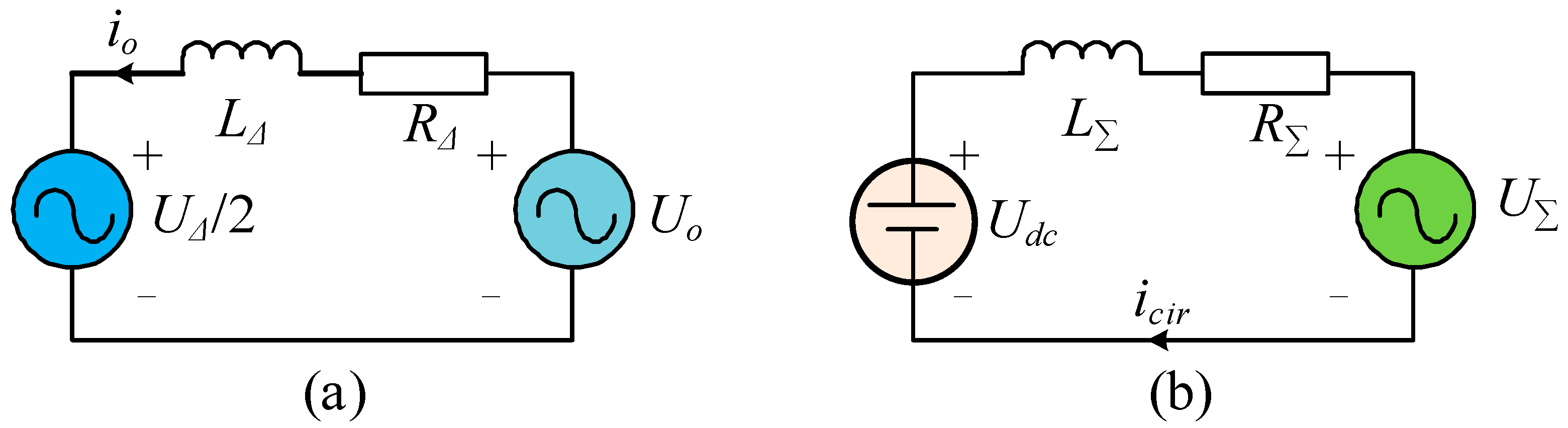
2.2. HSS Impedance Modeling of MMC

Equations (3)–(6) provide the basic MMC circuit equations. In contrast to the TL-VSC, the MMC topology exhibits intricate internal dynamics. This is evident in the submodule capacitance of the MMC topology, in which the submodule capacitance voltages interact with the harmonics in the circuit, resulting in a more intricate analysis. The HSS methodology was selected for the stability modeling to comprehensively consider the internal dynamics of the MMC system. Refer to Appendix A for the modeling procedure.
Figure 4 shows the block diagram of the modulation signal of the MMC control circuit controlled by the voltage control loop and the circuit current suppression control (CCSC) loop, from which the relationship between the modulation signals of the upper and lower arms and the control loop can be deduced:
m ˜ p ( s + j h ω 0 ) = G d m ( s + j h ω 0 ) u ˜ a + G c m ( s + j h ω 0 ) i ˜ c i r m ˜ n ( s + j h ω 0 ) = G d m ( s + j h ω 0 ) u ˜ a + G c m ( s + j h ω 0 ) i ˜ c i r
It should be noted that both u a * and i a * are fixed reference values that are unaffected by small signal disturbances, hence implying that both u a * and i a * are zero.
By substituting Equation (9) into Equation (A15), the AC side impedance Z0(s) can be obtained. For clarity in what follows, it is defined that the open-loop impedance Z0_ic(s) is the AC side impedance solely present in CCSC, while the closed-loop impedance Z0_close(s) is the AC side impedance present both in CCSC and voltage control.
The impedance of the MMC can be calculated using Equation (A23) and the circuit parameters detailed in Appendix B.
Figure 5 shows that the MMC impedance phase diagram under open-loop control remains in the range of ±90° with no negative damping characteristics, and the system is stable. In contrast, the MMC impedance phase diagram extends beyond ±90° under closed-loop control, indicating negative damping characteristics and risk of oscillation. At 14 Hz, the MMC intersects the power line impedance with a phase difference of over 180°, pointing towards a possibility of SSOs in the system. For the sake of clarity, this point will henceforth be referred to as the risk point.
The analysis of the figure above illustrates that the introduction of closed-loop control leads to negative damping characteristics, which in turn makes the MMC system unstable. As noted in the introduction, controller parameters affect stability. Therefore, it is necessary to investigate whether the negative damping characteristics, which cause instability in the MMC system, are due to the inappropriate selection of controller parameters.
Figure 6 compares the impedance plots of the MMC system voltage loop parameters KPdm and KRdm for different control parameters. As illustrated in Figure 6a, changing the control parameter KPdm has little effect on improving the negative damping characteristics of the MMC system. Figure 6b shows that increasing the parameter KRdm does not change the negative damping characteristics of the MMC system and even creates new risk points in the low-frequency range. In addition, if the KRdm parameter is excessively small, the impedance map under voltage control evolves into the open-loop impedance map. It can be concluded that if the KRdm parameter is too small, the control becomes ineffective, which falls outside the scope of this paper.
The analysis above shows that the negative damping characteristics of the MMC system are caused by the use of closed-loop control. Furthermore, systems using only PR control pose a risk of SSOs.

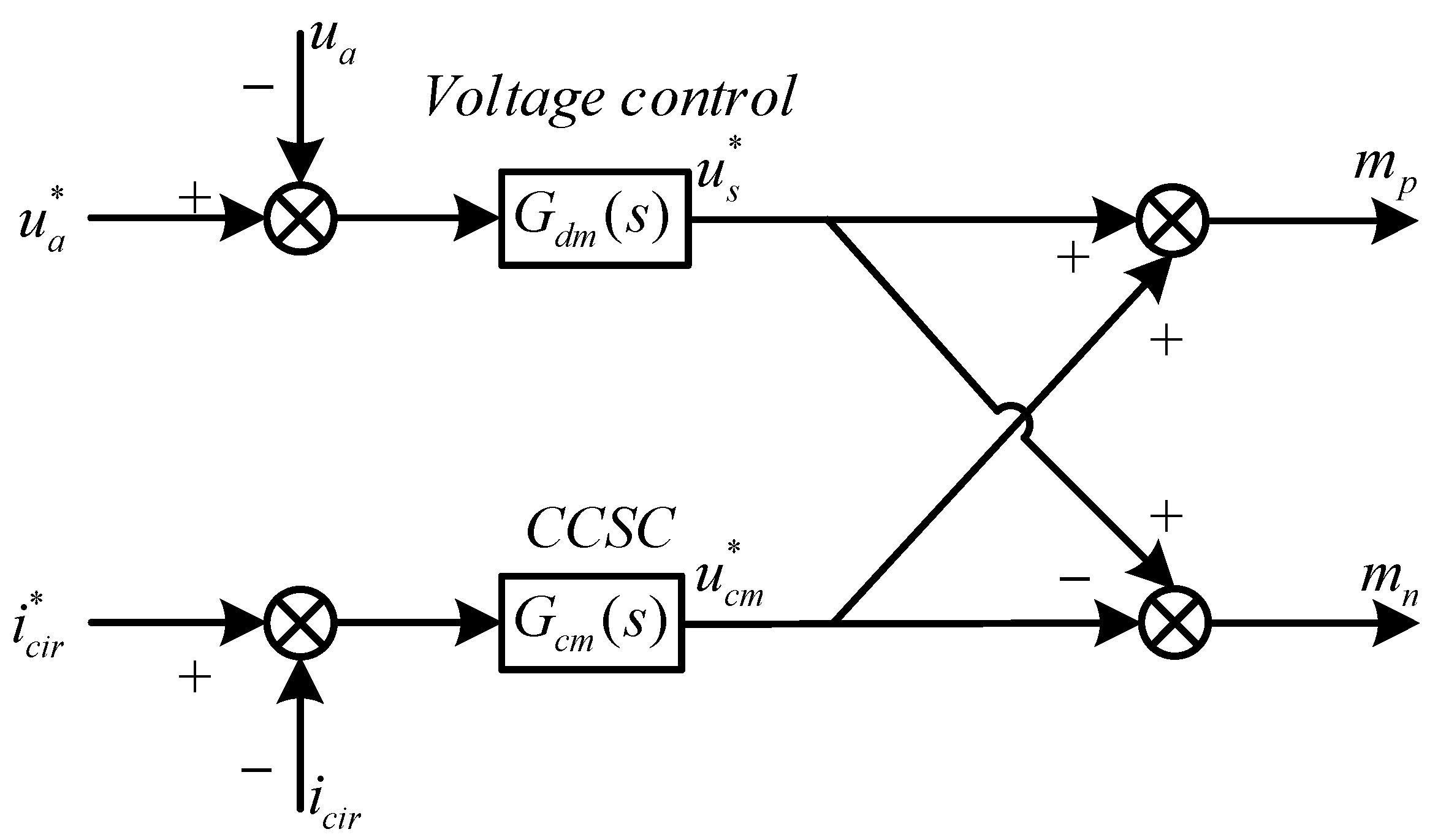
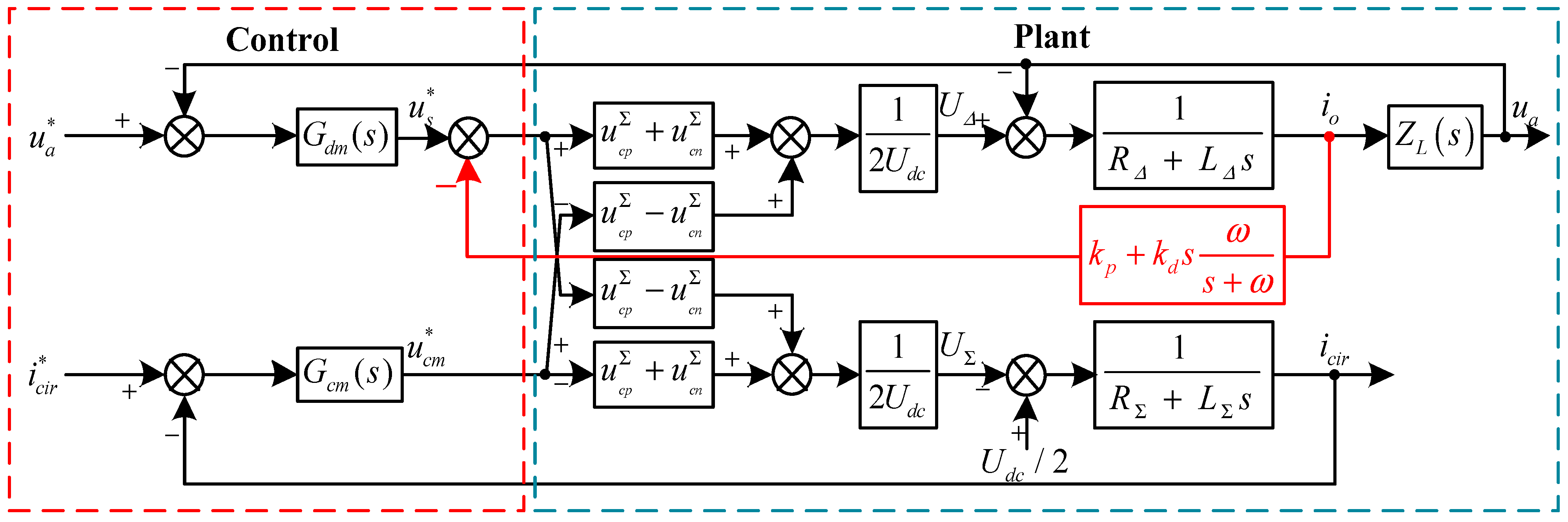
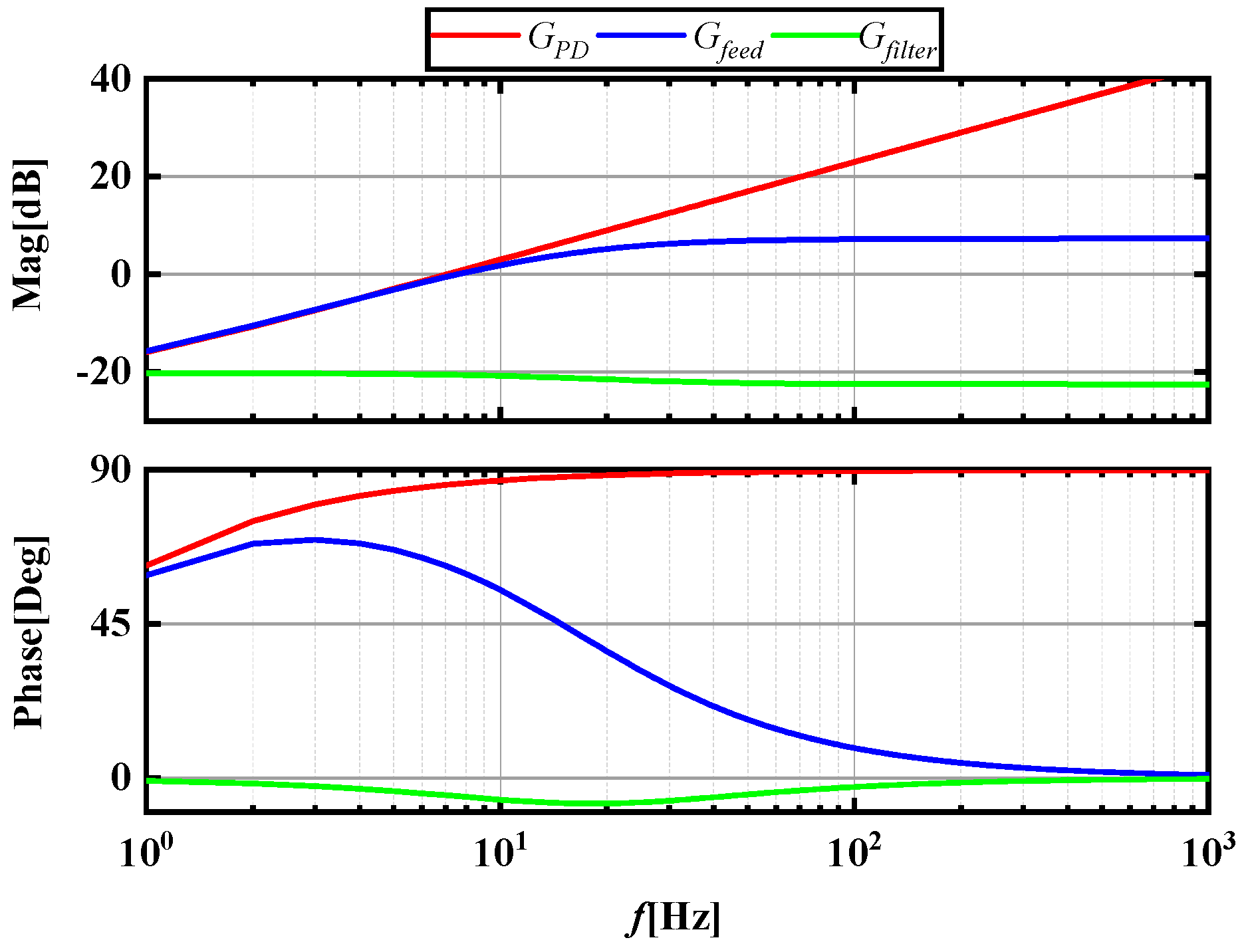
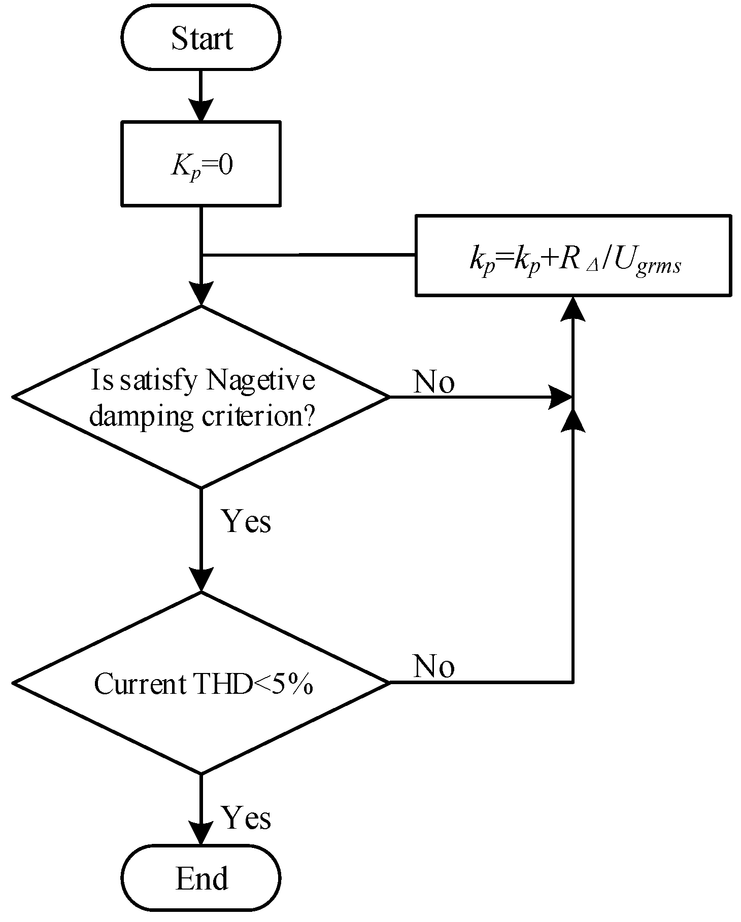
3. Proposed Method for Improving the Stability of MMCS Based on Impedance Reshaping

To confirm the risk of SSOs in the MMC system caused by negative damping characteristics, the current output io spectrum was simulated, and is presented in Figure 7, by the MATLAB/Simulink platform. The harmonic analysis reveals that when circuit control is switched from open-loop to closed-loop control, the system displays harmonics at both 17 Hz and 83 Hz frequencies due to mirror coupling [30]. The oscillation frequency coincides closely with the risk point frequency shown in Figure 5, confirming the accuracy of the impedance modeling.
To mitigate the low-frequency harmonic and prevent SSOs, this paper suggests a feed-forward current compensation method to enhance the stability of the MMC system. Figure 8 shows the control block diagram of the proposed feed-forward current compensation. In Figure 8, the left side is the control block diagram of the MMC system, and the right side is the simplified plant diagram of the MMC system. This paper aims to improve the stability of the MMC system by implementing a feed-forward control compensation path between the output current io and the control circuit. This path suppresses harmonic currents in the output current, reshapes the impedance, and achieves harmonic suppression in the control loop.
The magnitude of the output current is obtained by subtracting the upper and lower arms UΔ and multiplying by the differential mode resistor RΔ and differential mode inductor LΔ, as illustrated in Figure 8, to obtain the output voltage ua. To output the harmonic current back to the voltage modulation signal in the modulation circuit, the current must first be converted into a voltage form. This process can be achieved through a PD controller (transfer function GPD = kp + kd s).
In engineering applications, the use of PD controllers may result in high-frequency noise amplification. To address this issue, a first-order filter is added to adjust the poles, which works at attenuating the high-frequency noise of the differential link [31]. The value for ω is often empirically set at 100.
The transfer function of the feed-forward control loop can be obtained and expressed based on the analysis provided above.
Figure 9 displays the Bode plot of GPD, Gfeed, and Gfilter. A comparison between GPD and Gfeed reveals that the addition of a low-pass filter effectively limits the high-frequency gain of GPD to the range of Gfeed, preventing the amplification of high-frequency signals by the transfer function. A comparison between Gfeed and Gfilter shows that the phase of Gfeed always precedes that of Gfilter, which is crucial to the effectiveness of the proposed feed-forward current method. Gfilter exhibits a decaying frequency response as frequency increases, while Gfeed maintains a consistent gain across frequencies.
G f e e d ( s ) = k p + k d s N s + N
G f i l t e r ( s ) = k p + k d N s + N
The modulation function of the proposed method using feed-forward current compensation can be obtained, as shown in Figure 4 and Figure 8.
m ˜ p ( s + j h ω 0 ) = G v d ( s + j h ω 0 ) u ˜ a + G i c ( s + j h ω 0 ) i ˜ c i r + G f e e d ( s + j h ω 0 ) i ˜ o m ˜ n ( s + j h ω 0 ) = G v d ( s + j h ω 0 ) u ˜ a + G i c ( s + j h ω 0 ) i ˜ c i r G f e e d ( s + j h ω 0 ) i ˜ o
By substituting the modulation function (12) into Equation (A15), the impedance after compensation using the feed-forward current is obtained. This is defined as Zo_proposed (s). To achieve harmonic suppression in the control loop, the design criterion for the feed-forward compensation path is used. The values of the parameters kp and kd are then designed concerning the differential mode resistance RΔ and differential mode inductance LΔ, which are associated with the output current io.
The parameters kp and kd are related in the following way:
k p k d = R Δ L Δ
The criterion for negative damping stability is also defined in Figure 5, which aids in designing the parameters of this system:
Re [ Z 0 ( s ) ] > 0
To satisfy the negative damping stability criterion, the value of kp is obtained by iteratively calculating kp, using the design criterion shown in Equations (13) and (14). The calculated kp value is then substituted into the simulation, with a reference to IEEE standard THD of not more than 5%, which is the main reference for the current power quality [32]. Figure 10 presents the specific iterative flowchart.
The MMC system’s improved impedance can be acquired by replacing the obtained kp and kd parameters in Equations (A20) and (A23).
Figure 11 shows the MMC system impedance before and after using the feed-forward current compensation method proposed in this paper with the improved voltage loop PIR controller proposed in the literature [33]. From Figure 11, it can be seen that although both the method proposed in this paper and the PIR controller can suppress oscillations, the PIR controller still has a negative damping region in the mid-frequency region, while the method proposed in this paper can eliminate the negative damping region.

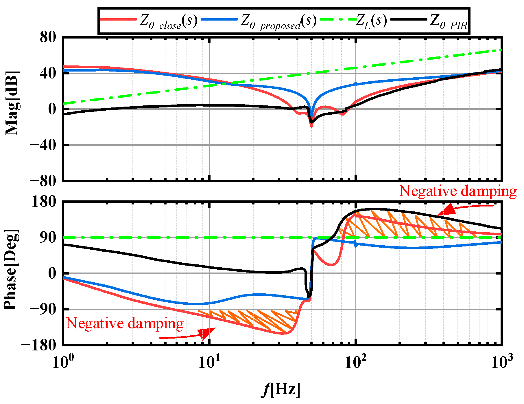
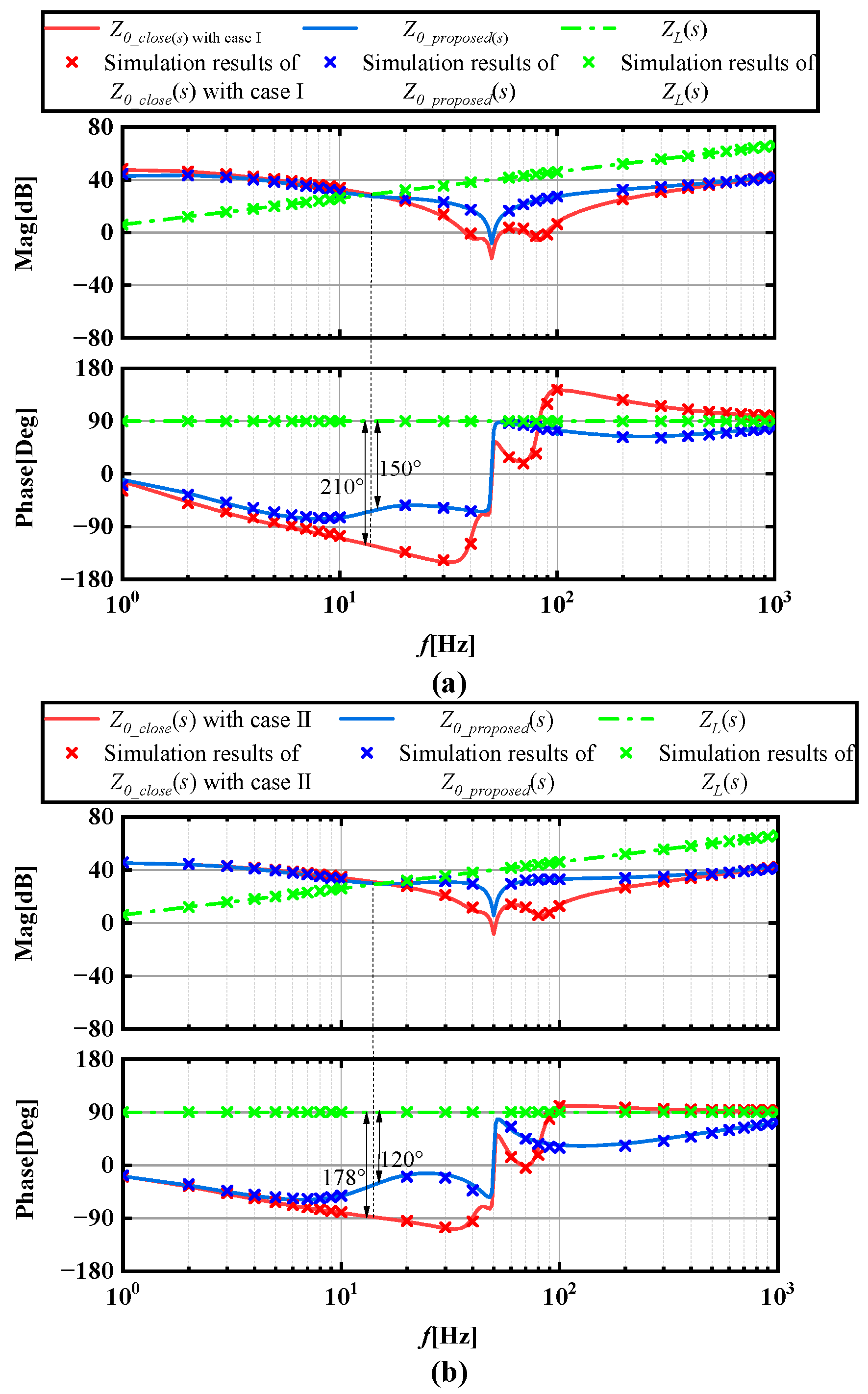
4. Case Study and Simulation Verifications

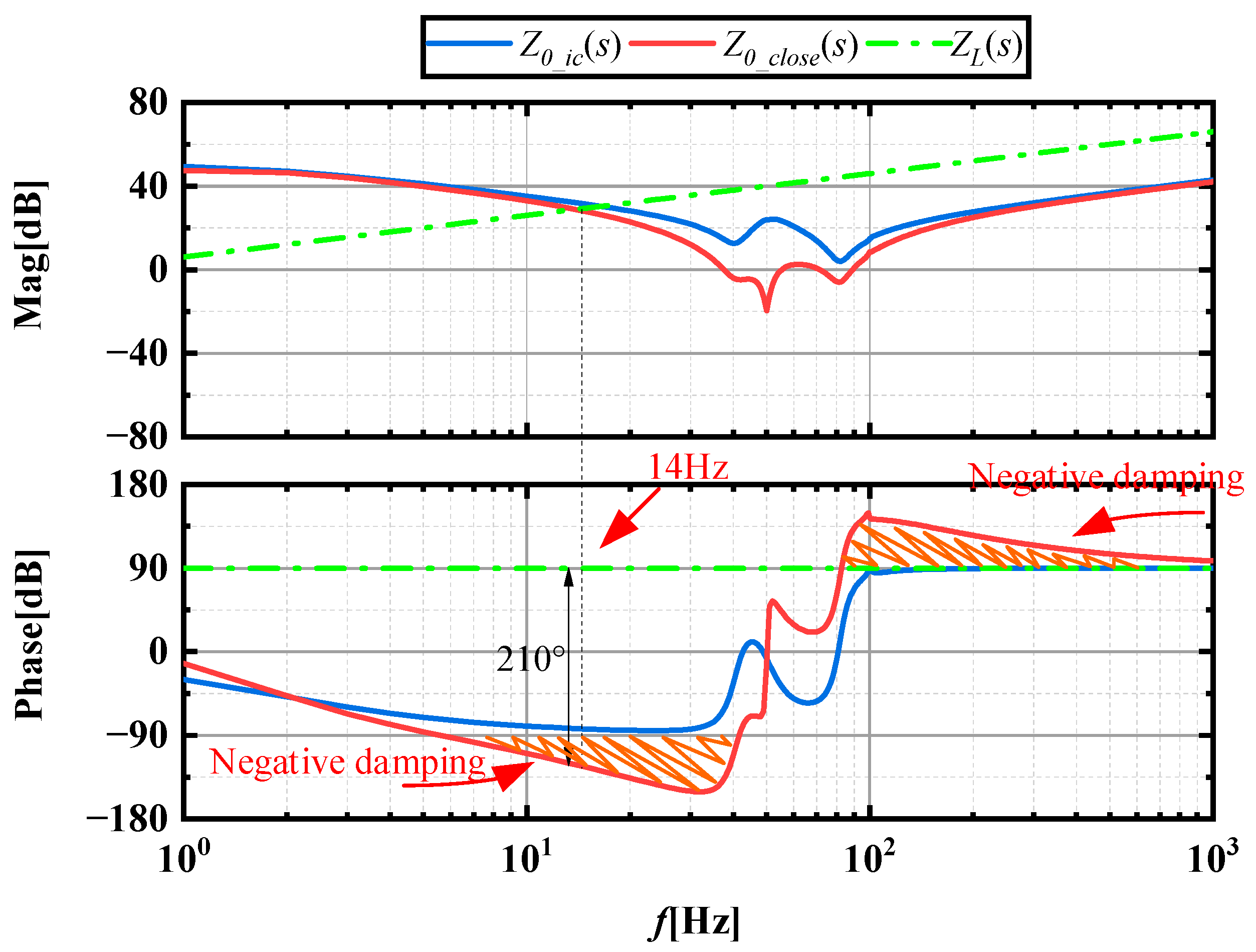
4.1. MMC Impedance Verification

To verify the accuracy of the theoretical analysis and the performance of the proposed impedance reshaping technique for the feed-forward current compensation of the MMC system, an MMC system was constructed on the MATLAB/Simulink platform for time domain simulation. The MMC system uses an exact model, and the parameter table is listed in Appendix B. To compare the effectiveness of the proposed feed-forward current compensation control, the consistent voltage loop parameters from the literature [33] are selected for verification of the proposed method. Table 1 lists the voltage loop circuit parameters.
Figure 12 shows the impedance Bode plots for voltage control and current feed-forward control. The symbol ‘x’ denotes the measured impedance at various frequencies, used to verify the theoretical impedance model.
Figure 12 shows that the scanning impedance results agree with the theoretical calculations. Specifically, Figure 12a shows that Zo_close(s) intersects the grid impedance magnitude with a phase difference greater than 180°, and that the system is unstable.

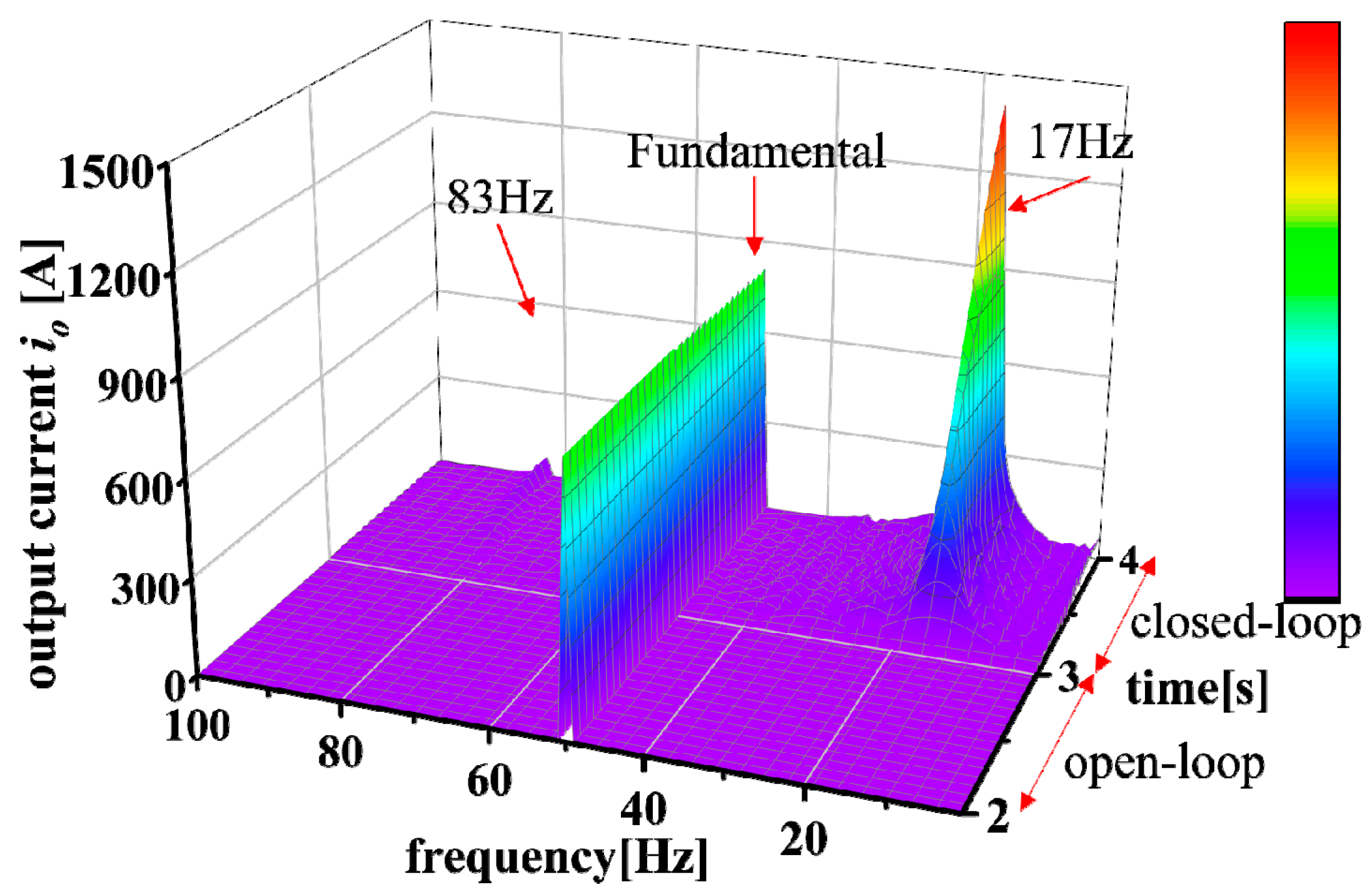
4.2. Feed-Forward Current Compensation Control under the Control of Different Voltage Controller Parameters

However, Zo_proposed (s) possesses the negative damping feature, which is removed through feed-forward current compensation control to attain stability. Figure 12b shows that the MMC intersects with the magnitude of the grid impedance, and that the phase margin is small. Simultaneously, the MMC system exhibits negative damping properties and may become unstable. The ensuing section verifies the aforementioned instability via simulation.
Figure 13a shows the time domain simulation results of the MMC system operating with the parameters given in Case I of Table 1. Figure 13b,c show the output current waveforms of the MMC system before and after using the feed-forward current compensation control. The disappearance of the 17 Hz harmonic and its corresponding mirror frequency, resulting in the 83 Hz harmonic, and effective suppression of the harmonics in the circuit can be observed in Figure 13 after the application of the feed-forward method. The results shown in Figure 12a demonstrate the stability of the MMC system after employing the feed-forward method.
The simulation results for the MMC system operating with the parameters from Case II, as specified in Table 1, are shown in Figure 14. The system exhibits low harmonic content due to the presence of negative attenuation characteristics. The feed-forward current compensation control method effectively suppresses harmonics in the circuit. This finding is consistent with the results shown in Figure 12b, which indicate that the proposed method stabilizes the MMC system and eliminates negative damping characteristics.

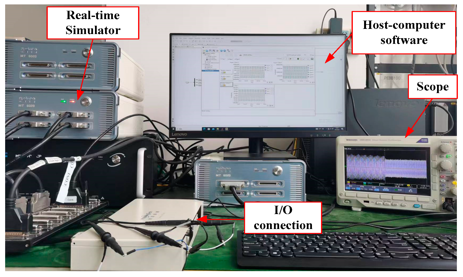
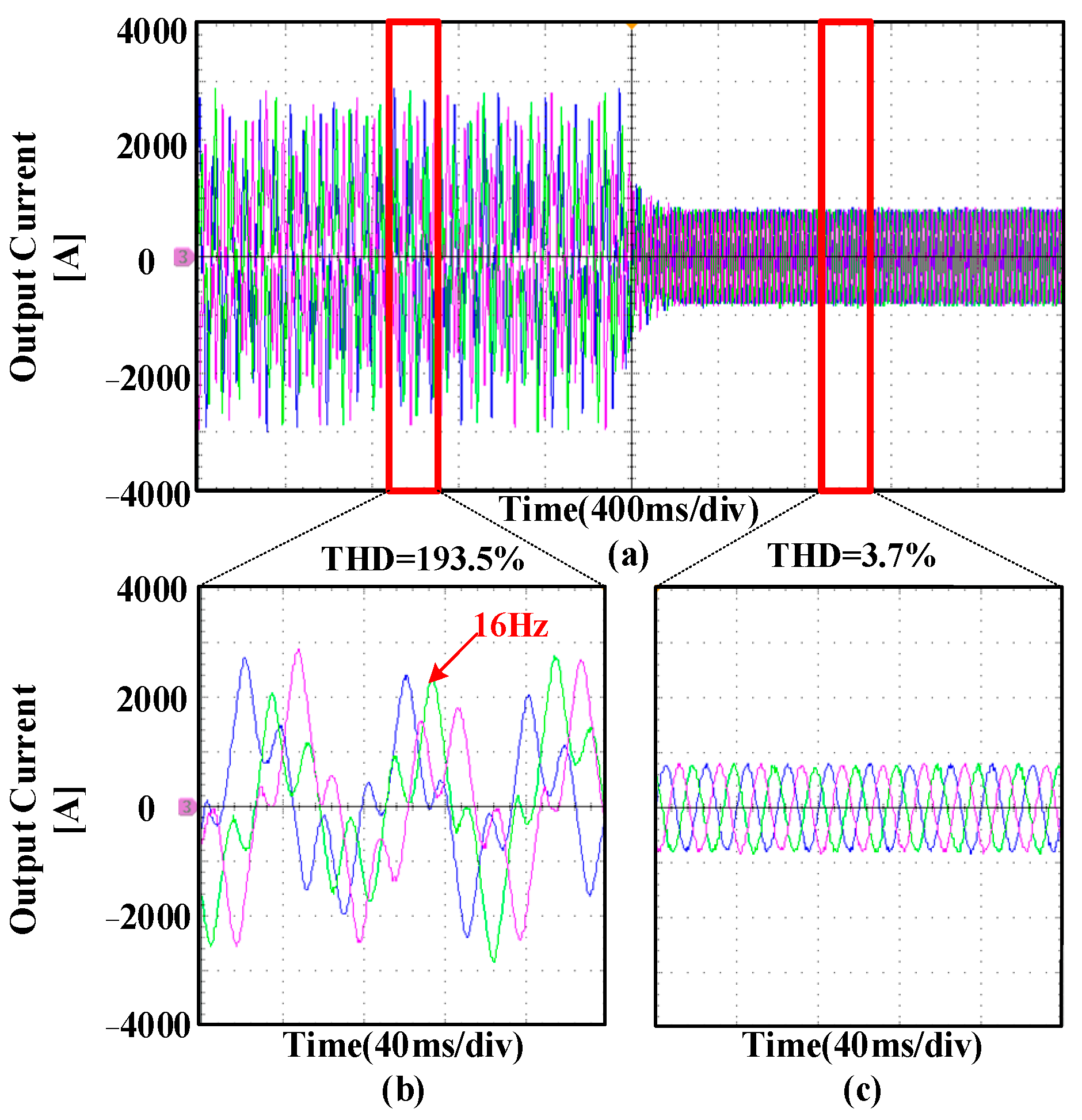
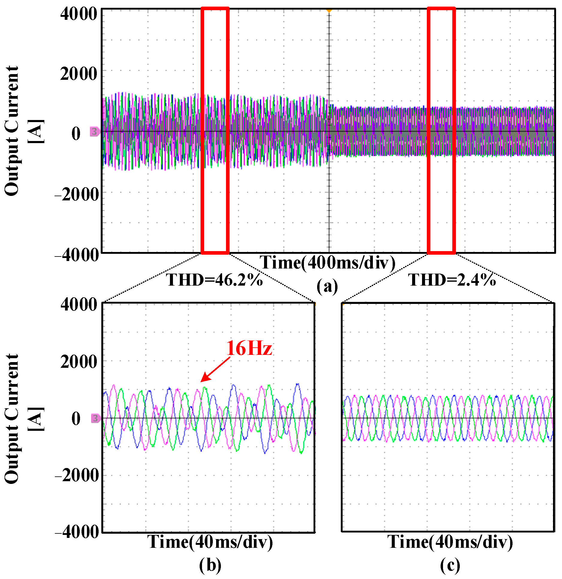
5. Experimental Verification

For further verification of the proposed feed-forward current compensation method, a hardware-in-the-loop experimental platform was constructed for the MMC system with a standalone grid, as illustrated in Figure 15. The MMC system uses an average model, and the parameter table is included in Appendix B. The experimental platform comprises the host computer StarSim HIL Advanced 5.0.0.0, StarSim real-time simulator, input/output connection, and an oscilloscope.
Before 2 s, the circuit with parameters from Case I in Table 1 exhibits the SSO, as demonstrated in Figure 16a. Harmonic currents within the oscillation are mainly at 16 Hz, with the maximum current magnitude reaching 961 A. As depicted in Figure 16, these harmonic currents lead to a 193.5% total harmonic distortion (THD) and degrade the quality of the output current. The use of the feed-forward current compensation method mitigates the SSO phenomenon in the circuit beyond 2 s.
As seen in Figure 16, the current in the circuit is mainly at the fundamental frequency, with a THD value of 3.7%. The SSO is observed in the circuit with the parameters of Case II in Table 1 before 2 s, as illustrated in Figure 17a. During the oscillation, the 16 Hz harmonic currents prevail, reaching a maximum value of 296 A, causing a deterioration in the output current quality, resulting in a total harmonic distortion of 46.2%, as depicted in Figure 17b. The use of the feed-forward current compensation method eliminates the SSO in the circuit after 2 s. Consequently, the current frequency in the circuit is governed by the fundamental frequency, resulting in a total harmonic distortion of 2.4%, as depicted in Figure 17c.
The differences between the experimental results obtained using the StarSim hardware-in-the-loop platform and those obtained using the MATLAB/Simulink platform can be attributed to two main reasons. Firstly, the MMC models used on the two platforms are different, indicating a certain level of inaccuracy in the average value model. Secondly, the time step used on each platform differs; the StarSim HIL hardware-in-the-loop platform uses a simulation step size of 100 us, while the MATLAB/Simulink platform is set to 10 us.
Table 2 lists the similarities and differences between the methodology proposed in this paper and other references.

6. Conclusions

In this study, a novel stability enhancement method based on impedance reshaping is proposed for standalone MMC control systems. Initially, the stability of MMC controllers using open- and closed-loop control was compared using the HSS method. Our model identifies the negative damping region within the MMC during voltage control. The mutual coupling between the impedance of the MMC and the power line within this region induces SSO. Subsequently, we propose a damping method using a current feed-forward compensation impedance reshaping method based on the presence of 16 Hz harmonic currents at SSO. This damping method is based on an improved proportional–derivative controller, where the harmonic currents are fed back to the modulation signal to nullify the harmonic currents in the output current. The impedance map results demonstrate that the proposed method effectively eliminates the negative damping region and mitigates the SSO. Finally, this study corroborates the validity of the theoretical analysis through time domain simulation and hardware-in-the-loop experiments, establishing a sound basis for the proposed stability enhancement technique.

Author Contributions

Conceptualization, Y.Z., L.H., Y.Y., C.L. (Chun Li), C.L. (Chaoyi Luo), Z.S., X.Y., and H.F.; methodology, Y.Z., L.H., Y.Y., C.L. (Chun Li), C.L. (Chaoyi Luo), Z.S., and H.F.; software, Y.Z., L.H., Y.Y., C.L. (Chun Li), C.L. (Chaoyi Luo), Z.S., and H.F.; validation, Y.Z., L.H., Y.Y., C.L. (Chun Li), C.L. (Chaoyi Luo), Z.S., and H.F.; formal analysis, Y.Z., L.H., Y.Y., C.L. (Chun Li), C.L. (Chaoyi Luo), Z.S., and H.F.; investigation, Y.Z., L.H., Y.Y., C.L. (Chun Li), C.L. (Chaoyi Luo), Z.S., and H.F.; resources, Y.Z.; data curation, Y.Z.; writing—original draft preparation, Y.Z., L.H., Y.Y., C.L. (Chun Li), C.L. (Chaoyi Luo), Z.S., and H.F.; writing—review and editing, Y.Z. and H.F.; visualization, Y.Z. and H.F.; supervision, Y.Z. and X.Y.; project administration, Y.Z.; funding acquisition, Y.Z. All authors have read and agreed to the published version of the manuscript.

Funding

This work was supported by the Science and Technology Project of China Southern Power Grid Co., Ltd. (GZKJXM20222414).

Data Availability Statement

Data are contained within the article.

Acknowledgments

The authors would like to express their gratitude to the Science and Technology Project of China Southern Power Grid Co., Ltd.

Conflicts of Interest

Author X.Y., and H.F has received research grants from Electric Power Research Institute, Guizhou Power Grid Co., Ltd.

Abbreviations

AbbreviationsFull Name
MMCmodular multilevel converter
SSOsubsynchronous oscillation
HSSharmonic state space
HVDChigh-voltage direct current
SMsubmodule
DMdifferential mode
CMcommon mode
CCSCcircuit current suppression control
THDtotal harmonic distortion

Appendix A. HSS Modeling

To start with, by the principle of small signal analysis, we linearize the set of nonlinear differential equations that describe the basic circuit equations (Equations (3)–(6)) at the operating point:
Equations (Equations (3)–(6)) at the operating point:
d i ˜ o d t = R f L f i ˜ o m p L f u ˜ c p Σ + m n L f u ˜ c n Σ 2 L f U o U c p Σ L f m ˜ p + U c n Σ L f m ˜ n
d i ˜ c i r d t = R f L f i ˜ c i r m p 2 L f u ˜ c p Σ m n 2 L f u ˜ c n Σ 1 2 L f U ˜ d c U c p Σ 2 L f m ˜ p U c n Σ 2 L f m ˜ n
d u ˜ c p Σ d t = 1 C a r m m p i ˜ c i r 1 2 C a r m m p i ˜ o + 1 C a r m I c i r m ˜ p 1 2 C a r m I o m ˜ p
d u ˜ c n Σ d t = 1 C a r m m n i ˜ c i r + 1 2 C a r m m n i ˜ o + 1 C a r m I c i r m ˜ n + 1 2 C a r m I o m ˜ n
Writing Equations (A1)–(A4) into matrix form
x ˜ ˙ ( t ) = A ( t ) x ˜ ( t ) + B ( t ) u ˜ ( t ) + C ( t ) m ˜ ( t )
A ( t ) = [ R f L f 0 m p L f m n L f 0 R f L f m p 2 L f m n L f m p 2 C a r m m p C a r m 0 0 m n 2 C a r m m n C a r m 0 0 ]
B ( t ) = [ 2 L f 0 0 1 2 L f 0 0 0 0 ]
C ( t ) = [ U c p Σ L f U c n Σ L f U c p Σ 2 L f U c n Σ 2 L f I o 2 C a r m I c i r C a r m I o 2 C a r m I c i r C a r m ]
x ˜ ( t ) = [ i ˜ o ( t ) , i ˜ c i r ( t ) , u ˜ c p Σ ( t ) , u ˜ c n Σ ( t ) ] T
u ˜ ( t ) = [ u ˜ o ( t ) , u ˜ d c ( t ) ] T
m ˜ ( t ) = [ m ˜ p ( t ) , m ˜ n ( t ) ] T
The time domain model is converted to the harmonic frequency domain using the HSS method:
s x ˜ = ( A H S S Q ) x ˜ + B H S S u ˜ + C H S S m ˜
x ˜ = [ X ˜ h X ˜ 1 X ˜ 0 X ˜ 1 X ˜ h ] , X ˜ h = [ i ˜ o ( s + j h ω 0 ) i ˜ c i r ( s + j h ω 0 ) u ˜ c p Σ ( s + j h ω 0 ) u ˜ c n Σ ( s + j h ω 0 ) ]
u = [ U ˜ h U ˜ 1 U ˜ 0 U ˜ 1 U ˜ h ] , U ˜ h = [ u ˜ o ( s + j h ω 0 ) u ˜ d c ( s + j h ω 0 ) ]
m ˜ = [ M ˜ h M ˜ 1 M ˜ 0 M ˜ 1 M ˜ h ] , M ˜ h = [ m ˜ p ( s + j h ω 0 ) m ˜ n ( s + j h ω 0 ) ]
A H S S = Γ [ A ( t ) ]
B H S S = Γ [ B ( t ) ]
C H S S = Γ [ C ( t ) ]
Q = d i a g [ j h ω 0 j ω 0 j 0 j ω 0 j h ω 0 ]
Equation (A12) shows that a matrix containing the relationship between the state variables and the input variables is constructed by the HSS method, and the corresponding impedance values can be obtained by extracting the elements of the matrix corresponding to the relationship.
By extracting the elements of the matrix between the state variables i ˜ 0 and the input variables u ˜ o , the corresponding AC side conductivity matrix elements can be obtained.
i ˜ 0 = Y M M C u ˜ o Y M M C = [ Y 0 ( s j ω 0 ) Y 1 ( s ) Y 2 ( s + j ω 0 ) Y 1 ( s j ω 0 ) Y 0 ( s ) Y 1 ( s + j ω 0 ) Y 2 ( s j ω 0 ) Y 1 ( s ) Y 0 ( s + j ω 0 ) ]
i ˜ 0 = [ i ˜ 0 ( s j ω 0 ) i ˜ 0 ( s ) i ˜ 0 ( s + j ω 0 ) ]
u ˜ o = [ u ˜ o ( s j ω 0 ) u ˜ o ( s ) u ˜ o ( s + j ω 0 ) ]
Inverting Equation (A20) gives the AC side impedance matrix.
Z M M C = Y M M C 1 = [ Z 0 ( s j ω 0 ) Z 1 ( s ) Z 2 ( s + j ω 0 ) Z 1 ( s j ω 0 ) Z 0 ( s ) Z 1 ( s + j ω 0 ) Z 2 ( s j ω 0 ) Z 1 ( s ) Z 0 ( s + j ω 0 ) ]

Appendix B. MMC Parameters

SymbolDescriptionValue
Ugrms/kVRMS value of the ac output voltage100
Udc/kVDc side voltage200
f0/HzGrid frequency50
S0/kWRated output power100
Lf/mHArm inductance45
RfArm resistance0.15
C/mFCapacitance of the submodule33
NNumber of the submodule in each arm100
L0/mHLoad impedance318
KPdmProportional gains5 × 10−7
KRdmResonance gains7.5 × 10−4
ωvResonance bandwidthsπ

References

  1. Liu, Z.; Lv, X.; Wu, F.; Li, Z. Multi-Mode Active Inertia Support Strategy for MMC-HVDC Systems Considering the Constraint of DC Voltage Fluctuations. IEEE Trans. Power Deliv. 2023, 38, 2767–2781. [Google Scholar] [CrossRef]
  2. Guo, C.; Xu, L.; Yang, S.; Jiang, W. A Supplementary Damping Control for MMC-HVDC System to Mitigate the Low-Frequency Oscillation Under Low Inertia Condition. IEEE Trans. Power Deliv. 2023, 38, 287–298. [Google Scholar] [CrossRef]
  3. Pan, R.; Liu, D.; Liu, S.; Yang, J.; Kou, L.; Tang, G. Stability Comparison Between Grid-Forming and Grid-Following Based Wind Farms Integrated MMC-HVDC. J. Mod. Power Syst. Clean Energy 2023, 11, 1341–1355. [Google Scholar] [CrossRef]
  4. Lin, L.; Zeng, Q.; Zhu, J.; Shi, X.; Hu, J. High-Frequency Oscillation Mechanism Analysis and Suppression Strategy of Grid-Forming Control MMC-HVDC. IEEE Trans. Power Deliv. 2023, 38, 1588–1600. [Google Scholar] [CrossRef]
  5. Jia, K.; Dong, X.; Wen, Z.; Wu, W.; Bi, T. Harmonic Injection Based Fault Ride-through Control of MMC-HVDC Connected Offshore Wind Farms. IEEE Trans. Sustain. Energy 2023, 14, 1796–1806. [Google Scholar] [CrossRef]
  6. Yang, R.; Shi, G.; Zhang, C.; Li, G.; Cai, X. Internal Energy Based Grid-Forming Control for MMC-HVDC Systems with Wind Farm Integration. IEEE Trans. Ind. Appl. 2023, 59, 503–512. [Google Scholar] [CrossRef]
  7. Zhou, H.; Yao, W.; Zhou, M.; Ai, X.; Wen, J.; Cheng, S. Active Energy Control for Enhancing AC Fault Ride-Through Capability of MMC-HVDC Connected with Offshore Wind Farms. IEEE Trans. Power Syst. 2023, 38, 2705–2718. [Google Scholar] [CrossRef]
  8. Tang, G.; He, Z.; Pang, H.; Huang, X.; Zhang, X. Basic Topology and Key Devices of the Five-Terminal DC Grid. CSEE Power Energy Syst. 2015, 1, 22–35. [Google Scholar] [CrossRef]
  9. Paulo, M.S.; Almeida, A.D.O.; Almeida, P.M.D.; Barbosa, P.G. Control of an Offshore Wind Farm Considering Grid-Connected and Stand-Alone Operation of a High-Voltage Direct Current Transmission System Based on Multilevel Modular Converters. Energies 2023, 16, 5891. [Google Scholar] [CrossRef]
  10. Zou, C.; Rao, H.; Xu, S.; Li, Y.; Li, W.; Chen, J.; Zhao, X.; Yang, Y.; Lei, B. Analysis of Resonance Between a VSC-HVDC Converter and the AC Grid. IEEE Trans. Power Electron. 2018, 33, 10157–10168. [Google Scholar] [CrossRef]
  11. Yan, Z.; Xu, J.; Yu, G.; Bai, E.; Chen, W. Detailed Wideband Impedance Modeling and Resonance Analysis of Grid-Connected Modular Multilevel Converter. Energies 2023, 16, 4782. [Google Scholar] [CrossRef]
  12. Yan, Z.; Xu, J. Sequence Impedance Modeling and Analysis of Modular Multilevel Converter Considering DC Port Characteristics. Energies 2023, 16, 7770. [Google Scholar] [CrossRef]
  13. Guo, X.; Yuan, B.; Li, X.; Yin, C. Research on the High Frequency Oscillation of MMC-HVDC Integrated into Renewable Energy System. In Proceedings of the 2021 IEEE Southern Power Electronics Conference (SPEC), Kigali, Rwanda, 6 December 2021; IEEE: Piscataway, NJ, USA, 2021; pp. 1–6. [Google Scholar]
  14. Buchhagen, C.; Greve, M.; Menze, A.; Jung, J. Harmonic Stability-Practical Experience of a TSO. In Proceedings of the Wind Integration Workshop, Vienna, Austria, 14–17 November 2016; Volume 2016, pp. 1–6. [Google Scholar]
  15. Li, L.; Xu, C.; Enke, Y.U.; Xingwei, Y.U. Zhoushan Multi-Terminal VSC-HVDC Transmission Demonstration Project and Its Evaluation. South. Power Syst. Technol. 2019, 13, 10. [Google Scholar] [CrossRef]
  16. Lyu, J.; Cai, X.; Molinas, M. Optimal Design of Controller Parameters for Improving the Stability of MMC-HVDC for Wind Farm Integration. IEEE J. Emerg. Sel. Top. Power Electron. 2018, 6, 40–53. [Google Scholar] [CrossRef]
  17. Buchhagen, C.; Rauscher, C.; Menze, A.; Jung, D.J. BorWin1—First Experiences with Harmonic Interactions in Converter Dominated Grids. In Proceedings of the International ETG Congress, Bonn, Germany, 17–18 November 2015; Die Energiewende-Blueprints for the New Energy Age. VDE: Offenbach, Germany, 2015; pp. 1–7. [Google Scholar]
  18. Jamshidi Far, A.; Jovcic, D. Small-Signal Dynamic DQ Model of Modular Multilevel Converter for System Studies. IEEE Trans. Power Deliv. 2016, 31, 191–199. [Google Scholar] [CrossRef]
  19. Lyu, J.; Zhang, X.; Cai, X.; Molinas, M. Harmonic State-Space Based Small-Signal Impedance Modeling of a Modular Multilevel Converter With Consideration of Internal Harmonic Dynamics. IEEE Trans. Power Electron. 2019, 34, 2134–2148. [Google Scholar] [CrossRef]
  20. Ji, K.; Pang, H.; Yang, J.; Tang, G. DC Side Harmonic Resonance Analysis of MMC-HVDC Considering Wind Farm Integration. IEEE Trans. Power Deliv. 2021, 36, 254–266. [Google Scholar] [CrossRef]
  21. Cespedes, M.; Xing, L.; Sun, J. Constant-Power Load System Stabilization by Passive Damping. IEEE Trans. Power Electron. 2011, 26, 1832–1836. [Google Scholar] [CrossRef]
  22. Xue, Y.; Xu, Z.; Tang, G. Self-Start Control With Grouping Sequentially Precharge for the C-MMC-Based HVDC System. IEEE Trans. Power Deliv. 2014, 29, 187–198. [Google Scholar] [CrossRef]
  23. Zhu, Y.; Pou, J.; Konstantinou, G. Impedance Shaping Effects and Stability Assessment of Circulating Current Control Schemes in Modular Multilevel Converters. IEEE Trans. Power Deliv. 2023, 38, 666–676. [Google Scholar] [CrossRef]
  24. Li, Y.; An, T.; Zhang, D.; Pei, X.; Ji, K.; Tang, G. Analysis and Suppression Control of High Frequency Resonance for MMC-HVDC System. IEEE Trans. Power Deliv. 2021, 36, 3867–3881. [Google Scholar] [CrossRef]
  25. Li, Y.; Pang, H.; Kong, M.; Lu, J.; Ji, K.; Tang, G. Compensation Control and Parameters Design for High Frequency Resonance Suppression of MMC-HVDC System. CSEE JPES 2020, 7, 1161–1175. [Google Scholar] [CrossRef]
  26. Yang, S.; Liu, K.; Qin, L.; Zhu, S.; Xu, B.; Wang, Q. A Broadband Active Damping Method for High-Frequency Resonance Suppression in MMC-HVDC System. Int. J. Electr. Power Energy Syst. 2023, 146, 108791. [Google Scholar] [CrossRef]
  27. Dai, F.; Liu, S.; Wang, G.; Zeng, D. Coordinated Suppression Strategies for Passive and Active Resonances of the MMC-HVDC AC-side System on the Medium- and High-frequency Bands. IET Gener. Transm. Distrib. 2023, 17, 2963–2977. [Google Scholar] [CrossRef]
  28. Ludois, D.C.; Venkataramanan, G. Simplified Terminal Behavioral Model for a Modular Multilevel Converter. IEEE Trans. Power Electron. 2014, 29, 1622–1631. [Google Scholar] [CrossRef]
  29. Xiong, X.; Yang, Y.; Wu, C.; Zhao, C.; Blaabjerg, F. Improving the Stability of Standalone MMCs by Shaping the AC Side Impedance Using Insertion Index Compensation. IEEE J. Emerg. Sel. Top. Circuits Syst. 2022, 12, 81–89. [Google Scholar] [CrossRef]
  30. Zou, Z.; Liserre, M. Modeling Phase-Locked Loop-Based Synchronization in Grid-Interfaced Converters. IEEE Trans. Energy Convers. 2020, 35, 394–404. [Google Scholar] [CrossRef]
  31. Visioli, A. Practical PID Control; Advances in Industrial Control; Springer: London, UK, 2006; ISBN 978-1-84628-585-1. [Google Scholar]
  32. Langella, R.; Testa, A.; Alii, E. IEEE Recommended Practice and Requirements for Harmonic Control in Electric Power Systems. In IEEE Recommended Practice; IEEE: Piscataway, NJ, USA, 2014. [Google Scholar]
  33. Wu, H.; Wang, X.; Kocewiak, L.H. Impedance-Based Stability Analysis of Voltage-Controlled MMCs Feeding Linear AC Systems. IEEE J. Emerg. Sel. Top. Power Electron. 2020, 8, 4060–4074. [Google Scholar] [CrossRef]
Figure 1. Standalone MMC exact model topology.
Energies 17 00895 g001
Figure 2. Standalone MMC average model topology.
Energies 17 00895 g002
Figure 3. Equivalent circuit diagram of the MMC system: (a) differential mode circuit diagram; (b) common mode circuit diagram.
Energies 17 00895 g003
Figure 4. Block diagram of the modulation signal of the MMC.
Energies 17 00895 g004
Figure 5. Impedance Bode diagram for open-loop and closed-loop control.
Energies 17 00895 g005
Figure 6. Closed-loop impedance Bode diagram for different voltage loop parameters.
Energies 17 00895 g006
Figure 7. Output current change after SSO event.
Energies 17 00895 g007
Figure 8. Block diagram of the control of an isolated MMC system.
Energies 17 00895 g008
Figure 9. Bode diagram of conventional controller GPD vs. Gfeed vs. Gfilter.
Energies 17 00895 g009
Figure 10. Impedance modeling evaluation flowchart for forward current compensation methods.
Energies 17 00895 g010
Figure 11. Bode diagram of the impedance the proposed method and [33].
Energies 17 00895 g011
Figure 12. Impedance scan verification: (a) Case I parameters; (b) Case II parameters.
Energies 17 00895 g012
Figure 13. Simulation results obtained for Case I: (a) time domain waveform; (b) enlarged oscillatory waveform; (c) enlarged stable waveform.
Energies 17 00895 g013
Figure 14. Simulation results obtained for Case II: (a) time domain waveform; (b) enlarged oscillatory waveform; (c) enlarged stabilized waveform.
Energies 17 00895 g014
Figure 15. StarSim HIL hardware-in-the-loop experiment platform.
Energies 17 00895 g015
Figure 16. Experimental results obtained for Case I: (a) experimental waveform; (b) enlarged view of oscillating waveform; (c) enlarged view of stabilized waveform.
Energies 17 00895 g016
Figure 17. Experimental results obtained for Case II: (a) experimental waveform; (b) enlarged view of oscillating waveform; (c) enlarged view of stabilized waveform.
Energies 17 00895 g017
Table 1. MMC output voltage regulator parameters.
Case StudyKPdmKRdm
Case I5 × 10−77.5 × 10⁻⁴
Case II5 × 10−71.5 × 10⁻⁴
Table 2. Comparative analysis of stability methods.
Refs.Oscillation
Frequency Type
Suppression MethodFeed-Forward Method
[24]High FrequencySecond-order damping controller, round controllerVoltage feed-forward
[25]High FrequencyFirst-order low pass filter, second-order, third-order band pass filterVoltage feed-forward
[26]High FrequencyAmplitude attenuation/
[27]Medium and high frequencyCombination of low-pass and high-pass filtersVoltage feed-forward
[33]Low FrequencyPIR controller/
ProposedLow FrequencyImproved PD controllerCurrent feed-forward
Disclaimer/Publisher’s Note: The statements, opinions and data contained in all publications are solely those of the individual author(s) and contributor(s) and not of MDPI and/or the editor(s). MDPI and/or the editor(s) disclaim responsibility for any injury to people or property resulting from any ideas, methods, instructions or products referred to in the content.

