Article

Assessing the Quantitative Risk of Urban Hydrogen Refueling Station in Seoul, South Korea, Using SAFETI Model

1
Department of Environmental and Safety Engineering, Ajou University, Suwon 16499, Republic of Korea
2
Department of Fire Safety Research, Korea Institute of Civil Engineering and Building Technology, Hwaseong 18544, Republic of Korea
*
Authors to whom correspondence should be addressed.
Energies 2024, 17(4), 867; https://doi.org/10.3390/en17040867
Submission received: 21 December 2023 / Revised: 1 February 2024 / Accepted: 8 February 2024 / Published: 13 February 2024
(This article belongs to the Section A5: Hydrogen Energy)

Abstract

:
Hydrogen refueling stations (HRS) operating at high pressures pose a higher risk of leakage than conventional gas stations. Therefore, in this study, a quantitative risk assessment (QRA) was conducted using DNV-GL SAFETI v.8.9. The impact of the shutoff valve was quantitatively assessed, and step-by-step mitigation was applied to propose the minimum installation requirements for the valve necessary to achieve broadly acceptable risk levels. The QRA includes sequence analysis (CA), individual risk (IR), and societal risk (SR), with accident scenarios consisting of catastrophic ruptures and three leak scenarios. The research results indicate that the application of a dual shutoff valve system resulted in an IR of 7.48 × 10⁻⁵, effectively controlling the risk below the as low as reasonably practicable (ALARP) criteria of the Health and Safety Executive (HSE). The SR was analyzed based on the ALARP criteria in the Netherlands, and the application of the dual shutoff valve system effectively controlled the risk below the ALARP criteria. Consequently, this study suggests that applying a dual shutoff valve system with a mitigation value exceeding 1.21 × 10⁻² can successfully mitigate the risk of urban hydrogen refueling stations to broadly acceptable levels.

1. Introduction

In response to climate change caused by greenhouse gas emissions, the international community is focusing on the development of renewable energy sources with lower carbon dioxide emissions [1]. Hydrogen is one of the most promising renewable energy sources to replace conventional fossil fuels. Hydrogen has a higher energy density (143 MJ/kg) than conventional fossil fuels such as gasoline (46.4 MJ) and diesel (45.4 MJ). It can be produced from renewable energy sources, such as fossil fuels, biomass, wind, and solar energy. Hydrogen is versatile and utilized in various fields, including households, industries, and transportation, for applications such as liquid fuel for ships and fuel cells in fuel cell vehicles (FCVs). Green hydrogen, produced through the electrolysis of water using only electrical energy, is considered a highly promising energy source with zero greenhouse gas emissions [2,3,4,5]. Consequently, South Korea announced its Hydrogen Economy Activation Roadmap in 2019, aiming to deploy 2.9 million hydrogen vehicles and establish 1200 hydrogen refueling stations (HRSs) by 2040 [6]. Hydrogen is a molecule with a very low density (0.089 g/L at 101.325 kPa, 0 °C). Therefore, in an HRS, where high-pressure processes are employed, gaseous hydrogen is compressed to enhance fluid energy density or liquefied below the boiling point of hydrogen (−253 °C or lower) through cryogenic processes for storage [7]. Currently, cryogenic processes for liquefied hydrogen refueling stations (LHRS) have not yet been commercialized in South Korea, and most HRSs operate as gaseous hydrogen refueling stations (GHRSs). Owing to its high-pressure operation, a GHRS poses the risk of hydrogen leakage through small cracks or joints in target facilities, such as tube trailers and storage tanks. Hydrogen leaked at high pressure can easily mix with ambient air because of its wide flammability range (4–75%) and low ignition energy (0.02 mJ), leading to spontaneous ignition and potential hazards, such as jet fires, fireballs, and vapor cloud explosions (VCEs) [8,9,10]. To minimize potential damage, South Korea applies separation distance criteria under the annex 5 for “Enforcement Regulations of High-Pressure Gas Safety Management Act” to HRS, securing the safety of nearby facilities [11].
Despite the increased risk of leakage compared with traditional gas stations [10,12], as HRSs have become more widespread, quantitative risk assessments (QRAs) have been conducted to demonstrate their safety. Kwak and Jongbeom [13] analyzed the safety of HRS based on jet fire modeling and overpressure modeling of PHAST 8.0, and HyRAM, along with an analysis of the suitability of HRS sites using French land use planning (LUP). They proposed the implementation of all possible safety measures during the HRS installation. Jeon et al. [9] performed a safety assessment of an operational urban HRS based on accident risk range and societal risk (SR). Based on the accident frequency analysis, the calculated risk impact range results were evaluated using a probit model, concluding that the risks of jet fires and overpressure during accidents were lower than the as low as reasonably practicable (ALARP) level. Sun et al. [14] conducted a QRA for a mobile HRS by dividing the study into operators, customers, and pedestrians. They found that the risks for operators and customers were acceptable, and for pedestrians, road risks were acceptable as long as well-planned routes and limited transportation times were implemented. Gye and Hye-Ri [15] performed a QRA on an urban HRS system to determine risk. To validate the need to apply a safety barrier system for risk reduction, they performed and compared the results of a frequency analysis. The application of a passive safety barrier system reduced the failure rate by ten times, resulting in a tenfold reduction in individual risk (IR) from 10−6 to 10−5, and the SR also confirmed its location within the ALARP range. Kikukawa et al. [16] conducted a risk assessment for an HRS that could use 70 MPa based on hydrogen station experiments at 40 MPa. Assuming explosion and jet fire scenarios were measured at distances of 1 m and 6 m from the leakage point, the results suggested that 6 m is a sufficient distance for the outer perimeter of the hydrogen station. Suzuki et al. [17] discovered through an IR analysis that the risk of jet fires accounts for over 90% of the HRS risk. To position the 10−6 risk contour within the boundary of the HRS site, the authors suggested the need for corresponding mitigation measures. Tsunemi and Kiyotaka [18] calculated the accident probability of hydrogen leakage by considering the failure probability and operating time of the valves and leak detectors in the event of an accident involving high-pressure gas compressor connection piping. They quantified the mitigation effects of firewalls and barriers and proposed the need for safety measures, such as firewalls, to protect devices and pipes. Park et al. [19] combined Layers of Protection Analysis (LOPA) and RiskCurve software to derive the IR and SR for HRS, assessing and comparing the risk and mitigation of applying independent protection layers (IPLs). Both the IR and SR showed high-risk contributions from the dispenser and tube trailer. In the case of IR, with the risk around the HRS sidewalk at 2.54 × 10⁻⁴, a passive IPL reduced it to 4.15 × 10⁻⁸, and an active IPL reduced it to 9.66 × 10⁻⁷. Similarly, the entry risk decreased from 7.63 × 10⁻⁵ to 7.13 × 10⁻⁹ with a passive IPL and 7.18 × 10⁻⁸ with an active IPL. The application of passive IPL met the ALARP criteria in the UK, Netherlands, and Hong Kong. While the active IPL contributed to a decrease in SR compared to having no IPL, its effectiveness was found to be less significant than that of a passive IPL. Therefore, the passive IPL was confirmed to be a more efficient mitigation measure that secured safety more effectively than an active IPL. Zhiyong L. I. et al. [20] divided the targets of the risk acceptance criteria for HRS into station personnel, customers, and parties. They compared the IR and SR before and after the application of safety barrier systems, such as leak detection and shutdown systems connected to emergency shutdown (ESD) systems on the dispenser and tube trailer, hydrogen sensors connected to the station’s automatic ESD system, and manual ESD buttons. For station personnel, there were no areas with a TR exceeding 10−4, and the maximum IR inside the station did not exceed 5 × 10⁻⁴. For customers, the probability of one or more fatalities decreased to 10−6 from 1.20 × 10⁻³ or 1.17 × 10⁻³. For the parties, safety distances were calculated and reduced from 23 m to 9 m, indicating a 61% reduction. Yoo et al. [7] derived the IR and SR for the GHRS and LHRS while proposing the installation of safety barrier systems, such as separated coupling, hydrogen detection sensors, and automatic and manual emergency shutdown buttons. The IR for LHRS (8.09 × 10⁻⁵) was lower than that of the GHRS (1.02 × 10⁻⁴), and the tube trailer accounted for 40% of the LHRS IR and 46% of the GHRS IR. Moreover, depending on the safety barrier system, the SR of the GHRS and LHRS decreased to 10−3.
In previous HRS studies, research on HRSs located in densely populated urban areas was limited, and QRAs were conducted to assume the hypothetical safety barrier system effects to achieve a risk level of 10−3 if the risk exceeded the ALARP criteria. In this system, where hydrogen leakage is fundamentally prevented, and fire or explosion is prevented, the quantitative performance of the valve has not been thoroughly studied. Therefore, this study aimed to quantitatively assess the risk of urban HRSs through a QRA, thereby proving the safety of urban HRSs. In this process, the study quantified the impact of a valve acting as an Active IPL, applied it as a single mitigation step, and compared the mitigation results. Finally, this study proposes the minimum installation requirements necessary to achieve the ALARP level and the minimum level of risk tolerance for urban HRS. This research is expected to be utilized as a study providing standards for minimum safety device installation for future urban HRSs and as fundamental data for designing safety-barrier systems, including valves. Furthermore, based on the results of the study, various levels of mitigation for safety barrier systems, including valves, can be designed.

2. Methodology

This study evaluated the risk of an HRS installed in the downtown area of Seoul, South Korea, and examined the mitigation effects of risk with the application of safety devices. Based on the necessary information for HRS in this study, risk was quantitatively assessed using QRA. DNV’s SAFETI v.8.9 was utilized for the QRA.

2.1. Scenario

2.1.1. HRS Selection

The research site is the Seosomun Government Complex in Seoul, South Korea. The target HRS, inaugurated on 7 October, 2022, is the first urban HRS in Seodaemun-gu, Seoul. Due to its failure to meet the required 17 m separation distance from a Grade 1 protected facility under South Korea’s “High-Pressure Gas Safety Management Act”, the operation of the target HRS was permitted with the condition of additional safety device installation through a regulatory exception granted by the Ministry of Trade, Industry and Energy. Figure 1 depicts the Seosomun Building HRS and its surrounding areas. To the west of the HRS is the Seoul Metropolitan Art Museum, which is designated as a Grade 1 protected facility under the High-Pressure Gas Safety Management Act. To the east are Seosomun Building 2 and the Seoul Metropolitan Council Building, and to the north are the Seosomun Building Welfare Center. To the south are Seosomun Building 5, commercial spaces, and various businesses.

2.1.2. HRS Specification

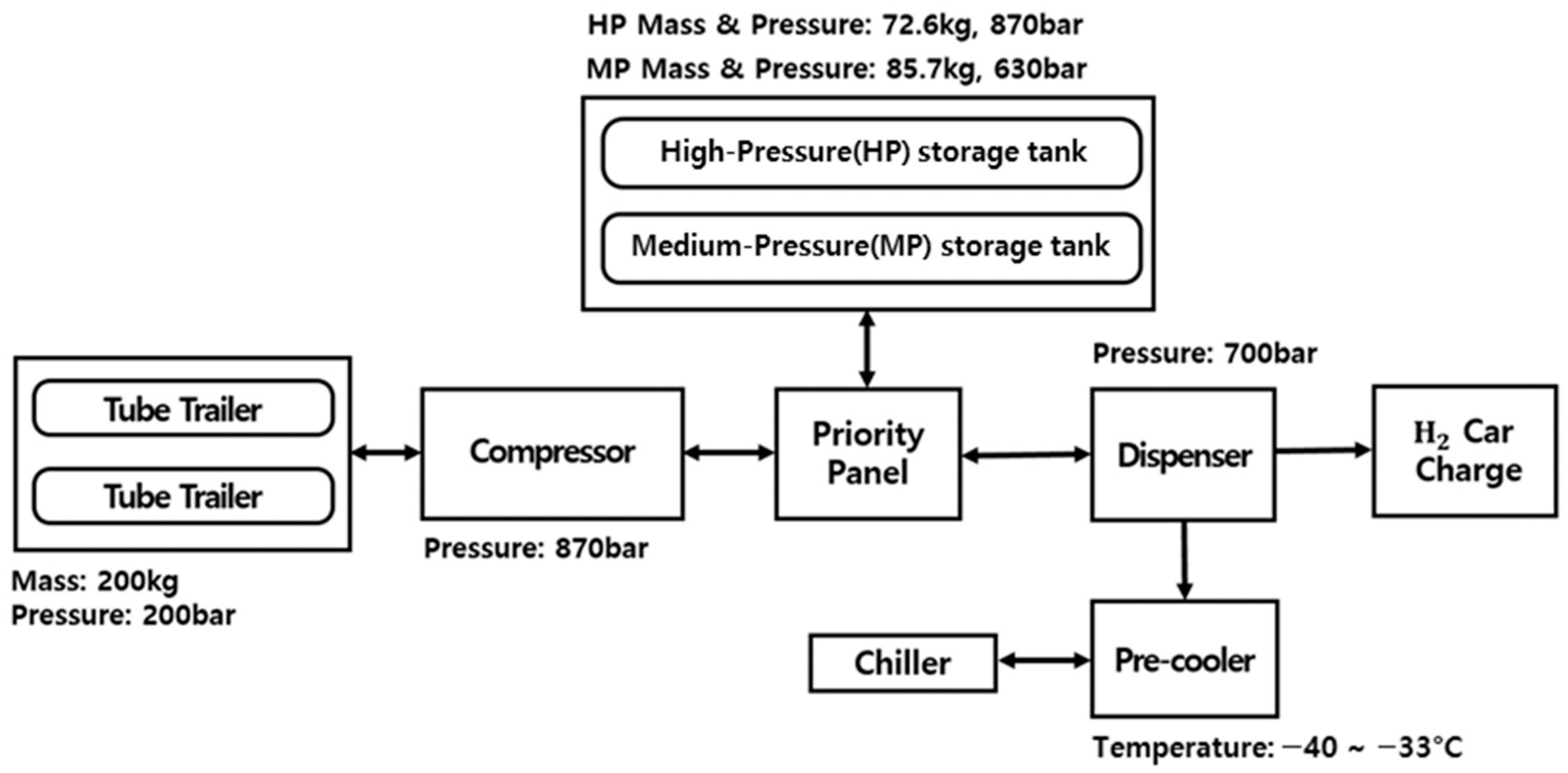
The operating conditions of the target HRS were established based on the process flow diagram (PFD) announced by Seoul Metropolitan City and the operation service task order provided by Seoul Energy Corporation [21,22]. The operating conditions of the target HRS are presented in Table 1, and those of the PFD are shown in Figure 2. This HRS receives hydrogen as an offsite station through tube trailers pressurized at 200 bar. Subsequently, the hydrogen was compressed and stored in storage tanks pressurized to 870 and 630 bar and supplied to the dispenser through the central control panel. The hydrogen supplied to the dispenser is cooled down to −40 °C through pre-coolers and chiller, and it charges hydrogen vehicles at 700 bar using pressure differentials. The operating conditions are listed in Table 1.
The accident scenarios for the HRS are presented in Table 2. The leak size and frequency of the HRS leakage scenario were referenced from Sandia National Laboratories’ (SNL) “SANDIA REPORT, SAND2009-0874 [10]”. According to SAND2009-0874, leakages in high-pressure storage tanks and tube trailers can stem from various components, including compressors, joints, cylinders, valves, pipes, and hoses. The leakage frequency for the target facility was calculated by aggregating the frequencies of all occurrences of these components. The leakage is assumed to originate from a circular leakage orifice, and the “leak size” denotes the diameter of the leakage orifice. The occurrence frequency of the catastrophic rupture scenario was determined based on the loss of containment frequency from the National Institute for Public Health and the Environment (RIVM)’s “Purple Book”, considering continuous all release within 10 min for stationary pressurized tanks and vessels [23].
To assess the potential risk based on the leakage frequency of the targeted facilities in a hydrogen refueling station (HRS), a comparison was conducted with the leakage frequency of existing gas station facilities. The leakage probabilities of the gas stations are listed in Table 3. The leak diameter and leakage frequency for the gas stations were obtained from the American Petroleum Institute (API) API 581 [12]. Leakage frequency data originated from the failure data of pressure vessels in petrochemical companies in Europe and the U.S. Similarly to SAND2009-0874, it was assumed that leakage occurred through a circular hole. For comparative analysis, the leakage frequency data for the HRS and gas station facilities considered only the large-leak scenario in the HRS and the small-leak scenario in gas stations with similar leak diameters. The results revealed that the targeted facilities in the HRS, operating under high pressure, exhibited a higher leakage frequency than those in the gas stations. This emphasizes the necessity of conducting quantitative risk assessments to derive the risks associated with an HRS and demonstrate its safety, especially when compared with gas station facilities.

2.1.3. Weather Condition

In this study, we aimed to verify the reduction in risk by applying safety devices based on the conservatively derived risk of the HRS. Consequently, we assessed the level of risk reduction and minimum installation requirements for safety devices. Therefore, weather conditions were assumed to be the worst-case scenario, according to the Chemical Accident Prevention and Management Plan of the National Institute of Chemical Safety (NICS) for South Korea [24]. The weather conditions in the worst-case scenarios are listed in Table 4.

2.1.4. Population Density

Population density in the research area was significantly influenced by the operating hours of the Seosomun Government Complex and the Seoul Museum of Art, with the resident population inside the buildings being dominant. The population density within the buildings was high during the operating hours from 09:00 to 18:00, when government officials at the Seosomun Government Complex and visitors to the Seoul Museum of Art were present. After 20:00, when these individuals remained, the population density decreased significantly. Therefore, population density was considered based on the ratio of day and night hours to the population inside the buildings. The surrounding indoor population ratios are presented in Table 5 [22,25], and the day-to-night ratios are presented in Table 6.

2.1.5. Mitigation Selection

The risks of jet fire, fireballs, and VCE are determined by factors such as the duration of hydrogen leakage, immediate ignition, and time to ignition [26]. In particular, the effective distance is significantly influenced by the duration of hydrogen leakage. Therefore, this study quantitatively evaluates the impact of emergency shutdown devices capable of preventing hydrogen leakage. The failure probabilities and operating times of the valves acting as emergency shutdown devices are listed in Table 7 [18,27,28,29].
Owing to the very short failure probability and operating time of check valves and excess flow valves, the quantitative evaluation of their impact based on their operation is challenging. Therefore, a shutoff valve was selected as the active IPL (independent protection layer) to mitigate the HRS risks.

2.2. QRA Program for HRS

In this study, the impacts of radiant heat and explosion overpressure resulting from jet fires, fireballs, and VCE were assessed using DNV-GL SAFETI v.8.9. Accordingly, the radiant heat and explosion overpressure calculation formulas for jet fires, fireballs, and VCE were selected and analyzed. An explanation of the quantitative risk assessment program used in this study can be found in Appendix A. Please refer to Table A1 in the Appendix B for a list of the parameters used in the calculation formulas.

2.2.1. Jet Fire Model

In this study, the impact of jet fires was evaluated using the Miller model [30,31]. For horizontal releases, Equation (1) represents the flame momentum length, Equation (2) represents the flame lift due to buoyancy, and Equation (3) represents the horizontal lift angle between the flame axis and the horizontal.
  F l a m e   m o m e n t u m   l e n g t h ,     B M = M A X 0 , M I N e 0.13 R i ( L B 0 ) , 1 L B O
F l a m e   l i f t   d u e   t o   b u o y a n c y ,     L y = M A X 0 , M I N 0.05 R i ( L B 0 ) , 1
δ h o r i z o n t a l = M A X 0 , M I N sin 1 L y L f B M , π 2 δ v e r t i c a l
Equation (4) represents the horizontal flame centerline length, which is independent of wind and has the same value as the zero-wind flame length. Equation (5) represents the flame wind buoyancy section length.
F l a m e   c e n t e r   l i n e   l e n g t h ,     L f = L B 0 = B M + R L
F l a m e   w i n d   b u o y a n c y   s e c t i o n   l e n g t h ,     R L = L f B M
Equation (6) expresses the horizontal flame length from the leakage hole to the flame tip.
F l a m e   l e n g t h   f o r   l e a k   h o l e   t o   f l a m e   t i p ,   L B = L y 2 + B M 2 + R L cos δ h o r i z o n t a l 2 + 2 R L B M cos δ h o r i z o n t a l cos φ f l a m e
Equation (7) represents the surface emissive power of the horizontal flame.
S u r f a c e   e m i s s i v e   p o w e r ,     W s u r f a c e = F m ˙ Δ H c , g a s A

2.2.2. Explosion Model

In this study, the Netherlands Organisation for Applied Scientific Research (TNO) Multi-Energy model was used [32]. The TNO Multi-Energy method, developed by Van den Berg, is an equation for calculating the explosion overpressure. It distinguishes explosion classes based on the scaled distance and intensity of the explosion overpressure, and derives the maximum overpressure of the explosion. The maximum overpressure and distance were scaled to non-dimensional parameters, as shown in Equations (8) to (10).
S c a l e d   p e a k   s i d e   o n   o v e r p r e s s u r e , P s = Δ P s P a
D y n a m i c   o v e r p r e s s u r e ,     P d y n = P d y n P a
S c a l e d   d i s t a n c e   f r o m   c e n t e r   o f   e x p l o s i o n , r = r E P a 1 3
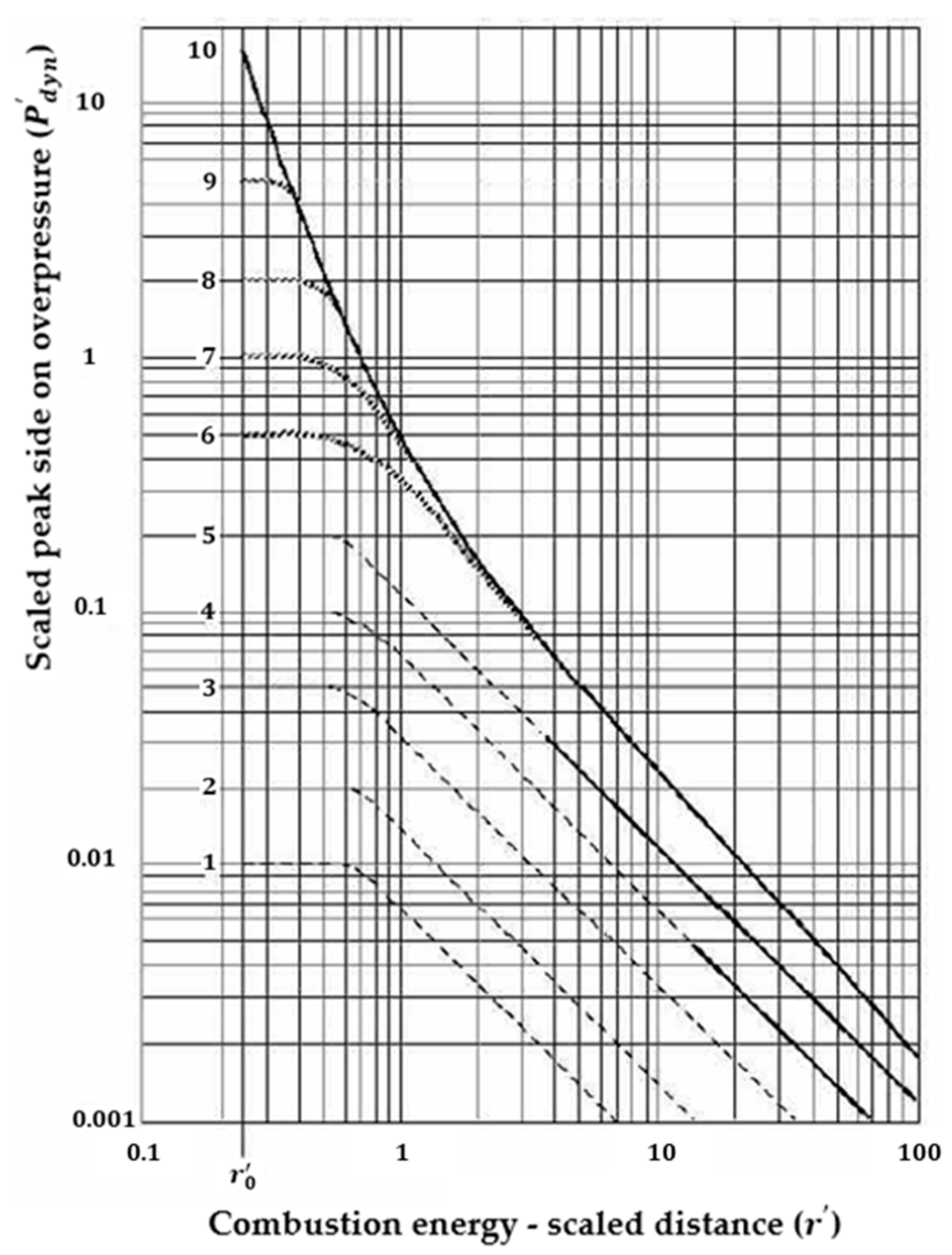
Subsequently, using a graph depicting the scaled overpressure based on the explosion class and scaled distance, the maximum overpressure of the explosion was determined. The explosion class is considered to be 1 for open spaces and 10 for the presence of obstacles, and is typically assumed to be 7 for general calculations. The peak side of the overpressure was calculated as shown in Figure 3.

2.2.3. Fireball Model

In this study, the impact of fireballs was evaluated using Martinsen and Marx’s dynamic models [33]. The fireball radius at elapsed time is represented by Equation (11).
r f i r e b a l l t = 4.332 M 1 / 4 t 1 / 3 , f o r   t t l o  
The surface emissive power was proposed based on Robert’s correlation, with an upper limit of 400 kW/m2. The surface emissive power is given by (12).
    E f i r e b a l l = M i n f M Δ H c , f u e l 0.8888 × 4 π r m a x 2 t d ,   400,000
Equation (12) can be written as Equation (13).
S u r f a c e   e m i s s i v e   p o w e r ,     E f i r e b a l l = M i n 0.0118 f M 1 / 12 Δ H c   ,   400,000

2.3. SR Analysis Method

2.3.1. Probit Model

The vulnerability of humans to toxicity, overpressure, and radiative heat can be calculated using a probit function [34]. The basic function of the probit model is given by Equation (14), where k 1 and k 2 are constants, and V represents the intensity based on the exposure time to radiant heat or overpressure.
P r = k 1 + k 2 × l n ( V )
For the radiation heat vulnerability model of SAFETI v.8.9, an equation was used based on the constants provided by the purple book of RIVM [23,35]. The vulnerability function of radiation heat is given by Equation (15), where Q represents the radiative heat.
P r H e a t = 36.38 + 2.56 × l n ( t × Q 4 / 3 )
For the overpressure vulnerability model in SAFETI v.8.9, the equation was based on constants provided by the Health and Safety Executive (HSE) [36,37]. The vulnerability function of the overpressure is given by Equation (16), where P s represents the peak overpressure.
P r O v e r p r e s s u r e = 1.47 + 1.35 × l n ( P s )
The criteria for radiation heat and overpressure intensity used to estimate human casualties were established as follows: The damage based on the radiant heat intensity is presented in Table 8, and that based on overpressure is listed in Table 9 [38,39,40].

2.3.2. Ignition Probability

The immediate ignition probability of hydrogen was obtained from analyses conducted using the SANDIA REPORT, SAND2009-0874 [10]. The ignition probabilities provided by SNL are listed in Table 10. The SNL distinguishes the ignition probabilities based on the hydrogen release rate. The peak release rates for the leakage scenarios of the target facilities are listed in Table 11. In this study, to obtain conservative results, the immediate and delayed ignitions were calculated as 0.053 and 0.027, respectively, based on the release rate of the large-leak scenario.

3. Results

3.1. CA of Leak Scenario

3.1.1. Results of Jet Fire

CA was performed using SAFETI v.8.9, deriving the effective distance to human casualties based on radiant heat and overpressure intensity without considering geographical features. In the leakage scenario, jet fires and VCEs occurred because of the restricted leak orifice. Because there was no significant difference in the peak flow rate of hydrogen according to the leakage scenarios of the target facilities, the impacts of radiation heat and overpressure due to jet fires and VCE showed similar results for all target facilities. The results of the jet fire in the leakage scenario are listed in Table 12.
For the high-pressure storage tank, in the scenario of a large leak, the length of the jet flame for the large leak was observed to be 21.07 m. The radiation heat impact extended downwind, influencing a distance of 34.28 m for 4 kW/m2. In the medium-leak scenario, the jet flame was 7.32 m, causing radiative heat impacts up to a downwind distance of 11.19 m for 4 kW/m2. In the small-leak scenario, the length of the jet flame was 2.53 m, resulting in radiation heat impacts up to a downwind distance of 3.28 m for 4 kW/m2. At a downwind distance of 1.62 m, the maximum radiation heat of 11.98 kW/m2 was observed.
For the medium-pressure storage tank, in the scenario of a large leak, the length of the jet flame for the large leak was observed to be 20.53 m. The radiation heat impact extended downwind, influencing a distance of 33.57 m for 4 kW/m2. In the medium-leak scenario, the length of the jet flame was 7.14 m, causing radiation heat impacts up to a downwind distance of 10.92 m for 4 kW/m2. In the small-leak scenario, the length of the jet flame was 2.45 m, resulting in radiation heat impacts up to a downwind distance of 3.16 m for 4 kW/m2. At a downwind distance of 1.57 m, the maximum radiation heat of 11.41 kW/m2 was observed.
For the tube trailer, in the scenario of a large leak, the length of the jet flame for the large leak was observed to be 19.88 m. The radiation heat impact extended downwind, influencing a distance of 33.22 m for 4 kW/m2. In the medium-leak scenario, the length of the jet flame was 6.95 m, causing radiation heat impacts up to a downwind distance of 10.85 m for 4 kW/m2. In the small-leak scenario, the length of the jet flame was 2.39 m, resulting in radiation heat impacts up to a downwind distance of 3.15 m for 4 kW/m2. At a downwind distance of 1.53 m, the maximum radiation heat of 11.82 kW/m2 was observed.

3.1.2. Results of VCE

The results of the VCE in the leak scenario are presented in Table 13. In the small-leak scenario, no explosions occurred. For the medium-scale leakage, explosions occurred at downwind distances of 10 m and 20 m, and for the large-leak scenario, an explosion occurred at a downwind distance of 40 m.
For the high-pressure storage tank, in the scenario of a large leak, an overpressure of 1 psi was observed within a radius of 35.55 m from the explosion center. In the medium-leak scenario, an overpressure of 1 psi was observed within a radius of 8.03 m from the explosion center.
For the medium-pressure storage tank, in the scenario of a large leak, an overpressure of 1 psi was observed within a radius of 34.99 m from the explosion center. In the medium-leak scenario, an overpressure of 1 psi was observed within a radius of 7.50 m from the explosion center.
For the tube trailer, in the scenario of a large leak, the overpressure of 1 psi was observed within a radius of 33.36 m from the explosion center. In the medium-leak scenario, an overpressure of 1 psi was observed within a radius of 7.25 m from the explosion center.

3.2. CA of Catastrophic Rupture Scenario

3.2.1. Results of Fireball

Fireballs and VCEs occur during the catastrophic rupture scenario. Unlike the leak scenario, the catastrophic rupture scenario does not calculate the peak flow rate based on factors, such as the size and pressure of the leak orifice. Therefore, the effective range owing to the fireball and VCE was determined using the tube trailer, which had the highest mass of hydrogen within the target facilities, yielding the largest results. The fireball results for the catastrophic rupture scenario are listed in Table 14.
For the high-pressure storage tank, the fireball diameter was 12.10 m and radiation heat of 4 kW/m2 was observed within a radius of 100.24 m from the fireball center.
For the medium-pressure storage tank, the fireball diameter was 12.79 m and the radiation heat of 4 kW/m2 was observed within a radius of 105.58 m from the fireball center.
For the tube trailer, the fireball diameter was 16.96 m and the radiation heat of 4 kW/m2 was observed within a radius of 137.87 m from the fireball center.

3.2.2. Results of VCE

The VCE results for the catastrophic rupture scenarios are presented in Table 15. The effective range of the explosion due to catastrophic rupture was calculated as the worst-case scenario based on the downwind distance in the direction of the human casualty criteria from the explosion center. For the high- and medium-pressure storage tanks, explosions occurred at downwind distance of 10 m and the tube trailer, explosion occurred at a downwind distance of 20 m.
In the high-pressure storage tank, an overpressure of 1 psi was observed within a radius of 81.69 m from the explosion center.
For the medium-pressure storage tank, an overpressure of 1 psi was observed within a radius of 86.96 m from the explosion center.
In the tube trailer, an overpressure of 1 psi was observed within a radius of 113.18 m from the explosion center.

3.3. IR Analysis

IR represents the probability of fatality at a specific location, calculated by multiplying the frequency of events defined by accident scenarios with the probability of those events causing fatalities. I R ( x , y ) denotes the total probability of fatality at a specific location ( x , y ) and can be expressed as in Equation (17). The total IR at each location represents the sum of the IR for all possible accident scenarios that can occur at that location, as calculated and expressed in Equation (18) [41].
I R x , y = F i P i x , y
I R ( x , y ) = i = 1 n F i P i ( x , y )
In this study, the frequency of event occurrence was defined based on the accident scenarios listed in Table 2. Subsequently, the frequency of events with the applied mitigation was also determined, considering the failure probability of the selected shutoff valve as a mitigation device (as defined in Table 7). Furthermore, considering the population density presented in Table 5 for day and night and the ratios provided in Table 6 for day and night, the IR results for day and night were combined and presented. The calculated IR results based on the application of the shutoff valve are presented in Table 16.
Risks expressed with a very low probability are distinguished by the as low as reasonably practicable (ALARP) concept. The ALARP concept is a crucial element in the risk assessment framework used to regulate and manage industrial risks, signifying that it is reasonably achievable or practicable [42,43]. ALARP evaluates risks into three levels defining the unacceptable and broadly acceptable risk levels: unacceptable (intolerable), acceptable (tolerable), and broadly acceptable. The risk-level criteria vary from country to country. In this study, the IR of HRS facilities was analyzed by evaluating the IR for operators and the public separately based on the HSE’s ALARP standards. HSE sets the acceptable risk level at 1 × 10⁻³ for operators and 1 × 10⁻⁴ for the public, considering risks below 1 × 10⁻⁷ as negligible for both operators and the public [44].
The analysis of IR for the HRS facilities revealed that, irrespective of the application of the shutoff valve, the influence of tube trailers was significant in all cases. The primary accident scenario for tube trailers was a jet fire in the case of a massive leakage scenario, constituting 99.92% of the accidents originating from tube trailers and contributing 76.32% of the total IR for tube trailers. The analysis results based on the scenarios showed that the risk associated with fireballs in the catastrophic rupture scenario was 99%, whereas in the leak scenario, jet fires accounted for over 99% of the total IR. The risk associated with jet fires and fireballs varies based on the amount of material involved in the fire and explosion and is heavily influenced by the leakage rate of the material. Consequently, the IR for the tube trailer with the highest leakage rate was the highest, whereas the IR for the HP and MP storage tanks with similar leakage rates were nearly identical. Without a shutoff valve, the total IR was 6.24 × 10⁻⁵, with the tube trailer IR at 2.93 × 10⁻⁵, constituting 47.11% of the total IR. With a single shutoff valve system, the total IR was 6.80 × 10⁻⁶, with tube trailer IR at 3.20 × 10⁻⁶, also constituting 47.11% of the total IR. With a double shutoff valve system, the total IR was 7.48 × 10⁻⁷ with tube trailer IR at 3.52 × 10⁻⁷, constituting 47.10% of the total IR. The total IR without a shutoff valve and with a single shutoff valve system is recommended to be within the acceptable risk range according to the HSE ALARP standards. The application of a double shutoff valve system mitigated the risk to levels below HSE’s broadly acceptable risk threshold.
Based on the calculated IR for each facility, Table 17 presents the IR for operators and the public. The IR for the Public was found to be at a broadly acceptable risk level even without mitigation through a shutoff valve. However, for the operators, the risk level was not within a broadly acceptable range, and mitigation through the application of a shutoff valve was deemed necessary.
In the case where the shutoff valve is not applied, the risk for the public is 7.91 × 10⁻⁷, and the risk for the operator is 6.16 × 10⁻⁵. The IR for the public was broadly acceptable, and that for the operator was at an acceptable risk level, which is recommended as a level within the acceptable risk range according to HSE standards.
With a single shutoff valve applied, the risk for the public is 5.21 × 10⁻⁸, and the risk for the operator is 6.75 × 10⁻⁶. The IR for the public decreased to a broadly acceptable risk level, while the IR for the operator still remained at an acceptable risk level, which is recommended to be mitigated to below 1 × 10⁻⁶.
In the case of applying a double shutoff valve system, the risk for the public is 5.73 × 10⁻⁹, and the risk for the operator is 7.43 × 10⁻⁷. Therefore, the application of a double shutoff valve system ensured that the IR for the public and the operator was secured at broadly acceptable levels and below broadly acceptable levels.
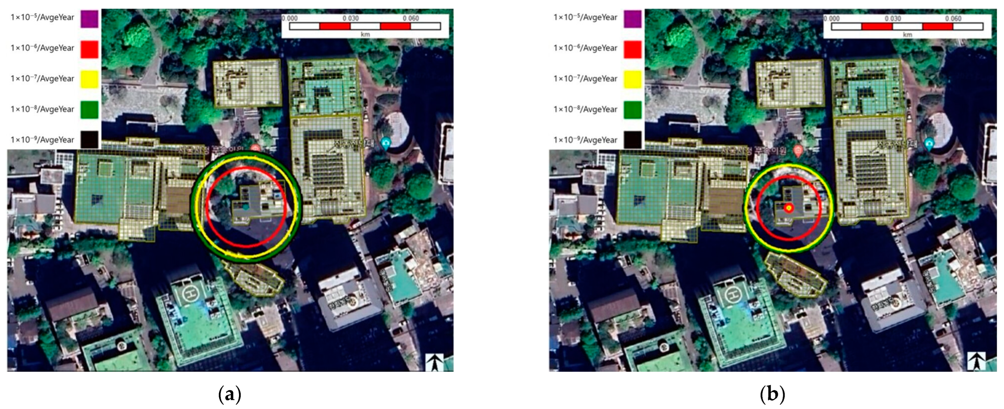
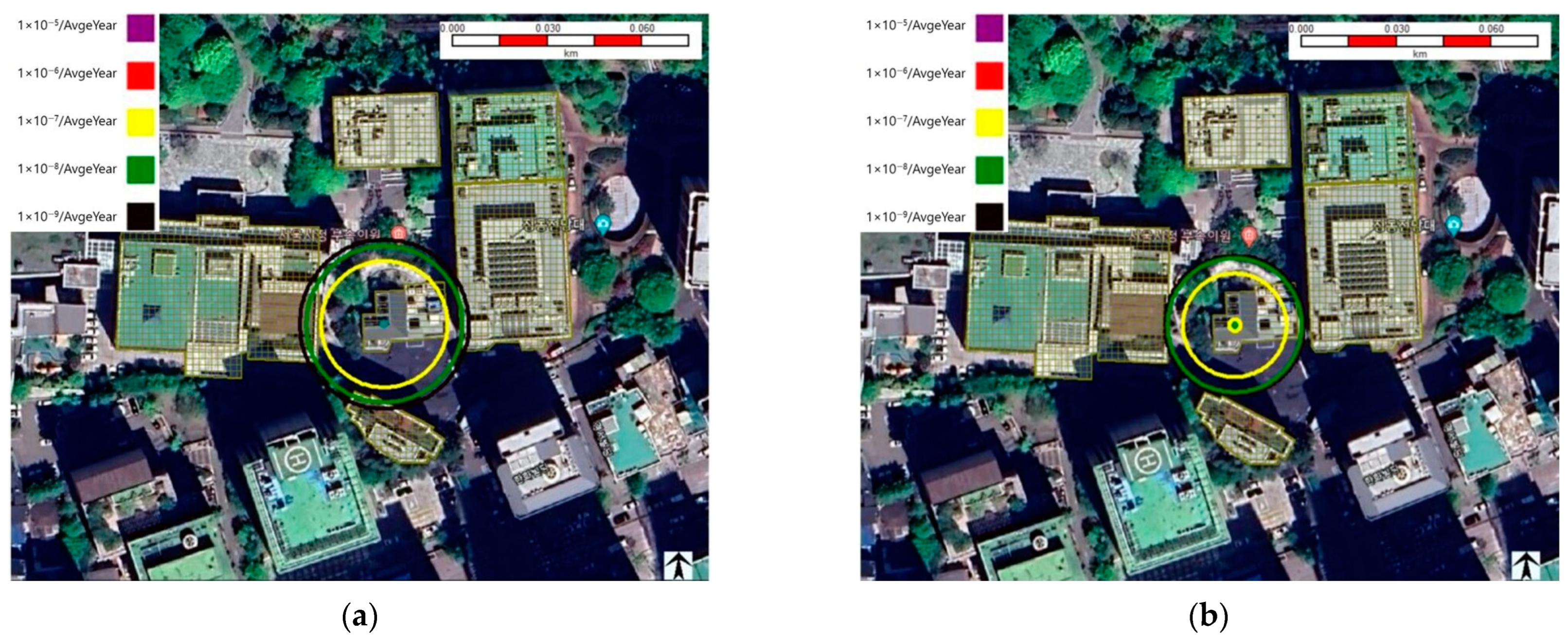
The contours of Outdoor and Indoor IR based on the application of the shutoff valve are presented in Figure 4, Figure 5 and Figure 6 and present the contours of Outdoor and Indoor IR based on the application of the shutoff valve. The IR contour reduced in size and frequency based on the application of the shutoff valve, and the double shutoff valve system significantly decreased the frequency of IR contours to below 1 × 10⁻⁷, with the range of contours not contacting the external walls of surrounding buildings.

3.4. SR of Each Case

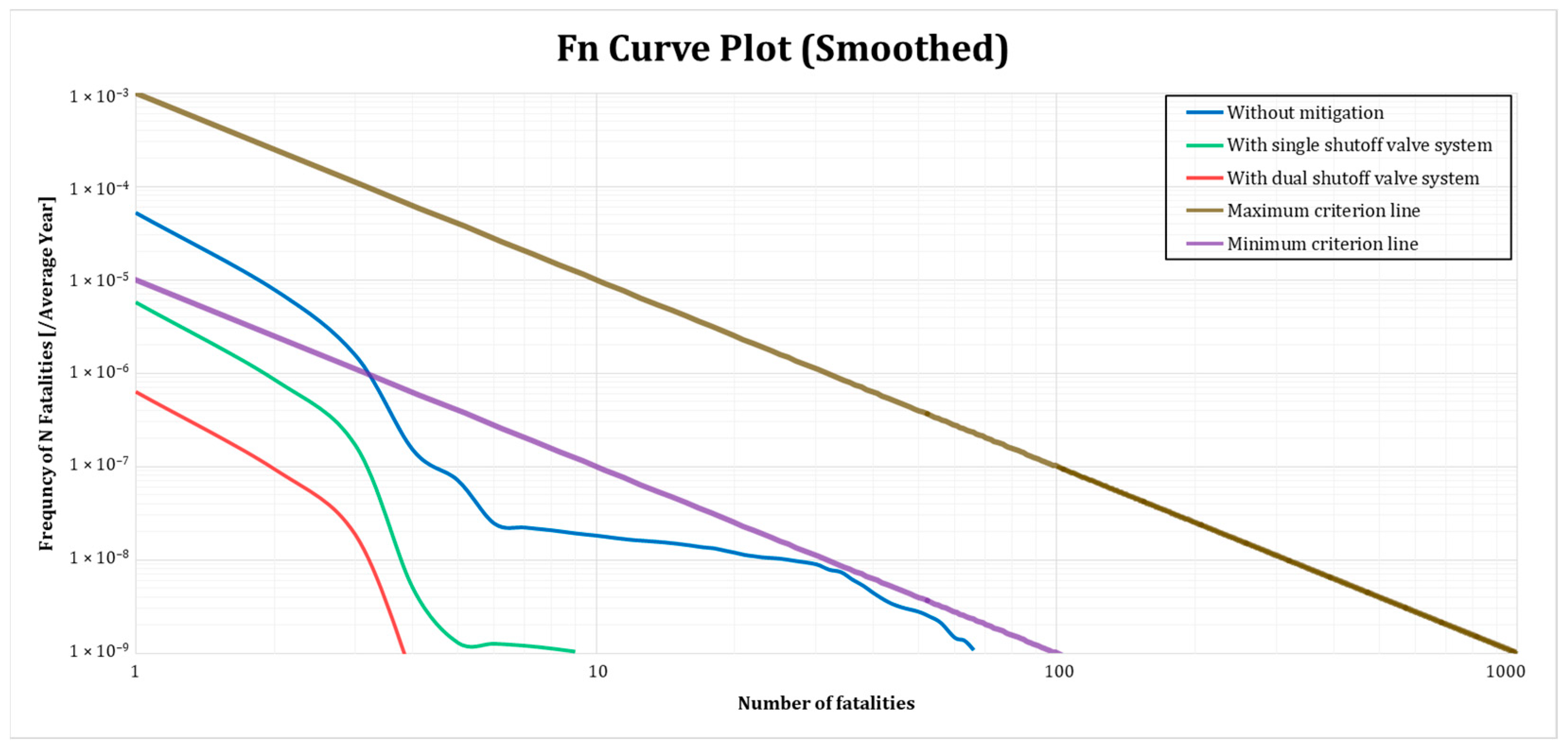
SR is expressed as a relationship between the frequency of occurrences and the number of fatalities. It is determined based on the sum of total IR for the facilities within the accident scenarios, considering the number of fatalities [41]. The SR for the case with the shutoff valve is shown in Figure 7. The SR is assessed based on the acceptable risk level and broadly acceptable level according to the ALARP. The UK HSE’s ALARP criteria set the maximum acceptable risk for the probability of one fatality at 1 × 10⁻² and the broadly acceptable risk at 1 × 10⁻⁴. In contrast, the ALARP criteria in the Netherlands set the maximum acceptable risk for the probability of one fatality at 1 × 10⁻³ and the minimum acceptable risk at 1 × 10⁻⁵ [45,46]. Therefore, in this study, the SR was analyzed using the ALARP criteria from the Netherlands to conservatively evaluate the reduction level of risk and propose minimum installation requirements for the shutoff valve.
The SR analysis results showed that the SR for the HRS without shutoff valve installation was within the ALARP criteria of the Netherlands, with a probability of one fatality of 5.22 × 10⁻⁵. When applying a single shutoff valve system, the probability of one fatality decreased to 5.75 × 10⁻⁶, placing the SR below the ALARP criteria. In particular, in the case of a dual shutoff valve system, the probability of one fatality significantly dropped to 6.32 × 10⁻⁷, well below the ALARP criteria, thus reducing the risk to a broadly acceptable level of 1 × 10⁻⁶. Therefore, to manage the risk of the target HRS below an acceptable level, it was confirmed that risk mitigation through the application of IPL with a value of 1.21 × 10⁻² or higher for the dual shutoff valve system is necessary.

4. Conclusions

In this study, a QRA for catastrophic rupture and leakage scenarios of a high-pressure storage tank, medium-pressure storage tank, and tube trailer in an HRS was conducted using SAFETI v.8.9. The QRA was performed using CA, IR, and SR analyses. This study examined the risk mitigation effects of applying a shutoff valve as a safety device in an HRS, proposed the minimum installation requirements for the shutoff valve to meet the ALARP criteria, and suggested the minimum mitigation requirements for other safety devices. The key findings are as follows.
  • In the CA analysis results for the leakage scenarios, there was little difference in the effective range of the jet fire and VCE among the target facilities because of their similar maximum leakage rates. However, for catastrophic rupture scenarios, the effective range was proportional to the mass, with the tube trailer having the largest impact range for fireballs and VCE. In the leakage scenarios, jet fire and VCE occurred, with jet fires occurring in all leak scenarios. The flame length of jet fires was around 20.5 m, and the impact distance up to 4 kW/m2 was around 33.5 m. VCE occurred only in large- and medium-leak scenarios, with the explosion occurring downwind at a distance of 40 m in the large-leak scenario and downwind distances of 20 m and 10 m in the medium-leak scenario. The impact distance of up to 1 psi was approximately 34 m for the large-leak scenario and approximately 7.5 m for the medium-leak scenario. In the catastrophic rupture scenario, fireball and VCE occurred, with fireball diameters of 12.1 m and 12.79 m for the HP storage tank and MP storage tank, respectively, and 16.96 m for the tube trailer. The impact distances up to 4 kW/m2 were approximately 100.24 m and 105.58 m for the HP storage tank and MP storage tank, respectively, and 137.87 m for the tube trailer. VCE occurred downwind at 10 m for both the HP storage tank and MP storage tank, with impact distances of approximately 81.69 m and 86.96 m, respectively. For the tube trailer, the VCE occurred downwind at 20 m, with an impact distance of up to 113.18 m.
  • In the IR analysis, regardless of the application of the shutoff valve, the tube trailer had the highest risk in all cases, contributing to over 47% of the total IR. The total IR for cases with and without a single shutoff valve system is recommended as an acceptable risk level within the HSE ALARP criteria. For the double shutoff valve system, the application effectively controlled the IR below the HSE ALARP criteria. The Total IR for the without shutoff valve case was 6.24 × 10⁻⁵, with IRs for the HP storage tank, MP storage tank, and tube trailer being 1.67 × 10⁻⁵, 1.63 × 10⁻⁵, and 2.93 × 10⁻⁵, respectively. For the single shutoff valve system case, the Total IR was 6.80 × 10⁻⁶, with IRs for the HP storage tank, MP storage tank, and tube trailer being 1.82 × 10⁻⁶, 1.78 × 10⁻⁶, and 3.20 × 10⁻⁶, respectively. In the double shutoff valve system case, the Total IR was 7.48 × 10⁻⁷, with IRs for the HP storage tank, MP storage tank, and tube trailer being 2.00 × 10⁻⁷, 1.96 × 10⁻⁷, and 3.52 × 10⁻⁷, respectively. Furthermore, the operator and public IRs were 6.16 × 10⁻⁵ and 7.91 × 10⁻⁷, respectively, for the without shutoff valve case, 6.75 × 10⁻⁶ and 5.21 × 10⁻⁸ for the single shutoff valve system case, and 7.43 × 10⁻⁷ and 5.73 × 10⁻⁹ for the double shutoff valve system case.
  • The SR for cases with and without the shutoff valve fell within the ALARP criteria in the Netherlands. The SR of the double shutoff valve system was effectively controlled below the Netherlands ALARP criteria. This indicates that the application of the double shutoff valve system or safety devices with a mitigation value exceeding 1.21 × 10⁻² can successfully manage the risk of urban HRS to a level below the broadly acceptable risk according to the Netherlands ALARP criteria.
Based on the research results, the installation of a dual shutoff valve system in urban hydrogen refueling stations (HRSs) is recommended to safely control the risk below the as low as reasonably practicable (ALARP) criteria. Additionally, installing a detector with the same mitigation value as the dual shutoff valve system is recommended to alleviate the frequency of accidents. In cases where accident prevention and mitigation devices with a value exceeding 1.21 × 10⁻² are not installed in urban HRS, additional protective barriers should be installed to directly mitigate the impact of accidents, or emergency evacuation manuals should be strengthened to minimize human casualties. This study can serve as fundamental data for designing safety barrier systems, including valves, in future research, and can be used as a basis for designing safety barrier systems with various levels of mitigation. Although this study aimed to compare the risk of an HRS with that of gas stations through a preliminary QRA using gas station leakage frequency, the lack of accident scenario regulations and resulting data in the preliminary research prevented a comprehensive evaluation. Therefore, in future research, we plan to utilize this study method to quantitatively assess the risk of existing gas stations and compare it with the risk of the HRS are required.

Author Contributions

Conceptualization, H.K.; methodology, H.K.; software, H.K.; validation, B.P.; formal analysis, H.K. and M.M.; investigation, H.K. and M.K.; data curation, H.K.; writing—original draft preparation, H.K.; writing—review and editing, S.J.; supervision, S.J.; project administration, S.J.; funding acquisition, B.P. All authors have read and agreed to the published version of the manuscript.

Funding

This research was supported by an internal grant (code: 20230436) from the Korea Institute of Civil Engineering and Building Technology (KICT), Republic of Korea. This research was supported by a Korea Institute for Advancement of Technology (KIAT) grant funded by the Korean Government (MOTIE) (P0012787, HRD Program for Industrial Innovation).

Data Availability Statement

Data are contained within the article.

Conflicts of Interest

The authors declare no conflicts of interest.

Appendix A

The DNV Safeti software package provides QRA solution for chemical and petrochemical facilities. Safeti integrated the PHAST results analysis software platform. PHAST uses various predictive model equations based on physical parameters to analyze process risks, including leaks, fires, and explosions, from the initial leaks to the final dispersion in chemical processes. These predictive model equations, along with user-provided leak frequencies, ignition data, weather data, population data, and vulnerability data, form the basis for calculating the risk of chemical accidents. Based on the impact assessment results obtained from PHAST, SAFETI combines the event tree results, population, and vulnerability to perform process risk analysis, providing IR and SR [26,47]. The IR and SR indicators include location-specific individual risk (LSIR) contours, FN curves, and the potential loss of life (PLL). Using risk-ranking points allows for the determination of risk at any location on the map and the identification of major risk contributors [48].

Appendix B

Table A1. Parameters used in the calculation formulas.
NameUnitsDescription
A m 2 Total surface area of the flame
B M mFlame momentum length
E JTotal combustion energy of the explosion
E f i r e b a l l kW/ m 2 Surface emissive power of fireball
F -Radiant heat fraction of horizontal flame
F i Fatality probability defined by accident scenario
f -Fraction of the total available heat energy
Δ H c , g a s kJ/kgHeat of combustion of gas
Δ H c , f u e l kJ/kgHeat of combustion of the fuel
I R x , y -Total probability of fatality at a specific location ( x , y )
i -Accident scenario
L B mFlame length for leak hole to flame tip
L B 0 mZero wind flame length
L f mFlame center line length
L y mFlame lift due to buoyancy
M kgMass of fuel involved in the fireball
m ˙ kg/sMass discharge rate
P a PaAtmospheric pressure
P d y n PaDynamic overpressure
P i -Frequency of events defined by accident scenario
P s PaPeak side on overpressure
P s PaScaled peak side on overpressure
R i -Richardson number
R L mFlame wind buoyancy section length
r mDistance from center of explosion
r mScaled distance from center of explosion
r f i r e b a l l t mFireball radius at elapsed time
r m a x mMaximum fireball radius
t secondsElapsed time
t d secondsFireball duration of dynamic model
t l o secondsLift-off time of fireball
W s u r f a c e kW/ m 2 Surface emissive power of horizontal jet flame
δ h o r i z o n t a l radiansHorizontal lift angle
δ v e r t i c a l radiansVertical lift angle
φ f l a m e radiansAngle between the vertical planes cutting the release source and jet flame, respectively, into symmetrical halves

References

  1. Amin, M.; Shah, H.H.; Fareed, A.G.; Khan, W.U.; Chyng, E.; Zia, A.; Lee, C. Hydrogen production through renewable and non-renewable energy processes and their impact on climate change. Int. J. Hydrogen Energy 2002, 47, 33112–33134. [Google Scholar] [CrossRef]
  2. Mazloomi, K.; Gomes, C. Hydrogen as an energy carrier: Prospects and challenges. Renew. Sustain. Energy Rev. 2012, 16, 3024–3033. [Google Scholar] [CrossRef]
  3. Shi, J.; Chang, Y. Methodological improvements in the risk analysis of an urban hydrogen fueling station. J. Clean. Prod. 2020, 257, 120545. [Google Scholar] [CrossRef]
  4. Oliveira, A.M.; Beswick, R.R.; Yan, Y. A green hydrogen economy for a renewable energy society. Curr. Opin. Chem. Eng. 2021, 33, 100701. [Google Scholar] [CrossRef]
  5. Dincer, I. Green methods for hydrogen production. Int. J. Hydrogen Energy 2012, 37, 1954–1971. [Google Scholar] [CrossRef]
  6. Korea Ministry of Trade Industry and Energy. Hydrogen Economy Roadmap (2019); Korea Ministry of Trade Industry and Energy: Sejong, Republic of Korea, 2019.
  7. Yoo, B.H.; Wilailak, S.; Bae, S.H.; Gye, H.R.; Lee, C.J. Comparative risk assessment of liquefied and gaseous hydrogen refueling stations. Int. J. Hydrogen Energy 2021, 46, 35511–35524. [Google Scholar] [CrossRef]
  8. Yang, N.; Deng, J.; Wang, C.; Bai, Z.; Qu, J. High pressure hydrogen leakage diffusion: Research progress. Int. J. Hydrogen Energy 2024, 50, 1029–1046. [Google Scholar] [CrossRef]
  9. Jeon, B.I.; Kim, S.; Yoon, Y.S.; Jung, S. Quantitative Risk Assessment of Hydrogen Refueling Station in Cheonan City of South Korea. Energies 2023, 16, 7138. [Google Scholar] [CrossRef]
  10. SAND2009-0874; Analyses to Support Development of Risk-Informed Separation Distances for Hydrogen Codes and Standards. Sandia National Laboratories: Albuquerque, NM, USA, 2009.
  11. Korea Ministry of Trade, Industry and Energy. Enforcement Regulation of High-Pressure Gas Safety Management Act (2024); Korea Ministry of Trade, Industry and Energy: Sejong, Republic of Korea, 2022.
  12. American Petroleum Institute. API Pub 581-2016 Risk-Based Inspection Technology; API Standards: New York, NY, USA, 2016. [Google Scholar]
  13. Kwak, J.; Lee, H.; Park, S.; Park, J.; Jung, S. Risk Assessment of a Hydrogen Refueling Station in an Urban Area. Energies 2023, 16, 3963. [Google Scholar] [CrossRef]
  14. Sun, K.; Pan, X.; Li, Z.; Ma, J. Risk analysis on mobile hydrogen refueling stations in Shanghai. Int. J. Hydrogen Energy 2014, 39, 20411–20419. [Google Scholar] [CrossRef]
  15. Gye, H.R.; Seo, S.K.; Bach, Q.V.; Ha, D.; Lee, C.J. Quantitative risk assessment of an urban hydrogen refueling station. Int. J. Hydrogen Energy 2019, 44, 1288–1298. [Google Scholar] [CrossRef]
  16. Kikukawa, S.; Yamaga, F.; Mitsuhashi, H. Risk assessment of Hydrogen fueling stations for 70áMPa FCVs. Int. J. Hydrogen Energy 2008, 33, 7129–7136. [Google Scholar] [CrossRef]
  17. Suzuki, T.; Shiota, K.; Izato, Y.; Komori, M.; Sato, K.; Takai, Y.; Miyake, A. Quantitative risk assessment using a Japanese hydrogen refueling station model. Int. J. Hydrogen Energy 2021, 46, 8329–8343. [Google Scholar] [CrossRef]
  18. Tsunemi, K.; Kihara, T.; Kato, E.; Kawamoto, A.; Saburi, T. Quantitative risk assessment of the interior of a hydrogen refueling station considering safety barrier systems. Int. J. Hydrogen Energy 2019, 44, 23522–23531. [Google Scholar] [CrossRef]
  19. Park, B.; Kim, Y.; Lee, K.; Paik, S.; Kang, C. Risk assessment method combining independent protection layers (IPL) of layer of protection analysis (LOPA) and RISKCURVES software: Case study of hydrogen refueling stations in Urban Areas. Energies 2021, 14, 4043. [Google Scholar] [CrossRef]
  20. Li, Z.; Pan, X.; Ma, J. Quantitative risk assessment on 2010 Expo hydrogen station. Int. J. Hydrogen Energy 2011, 36, 4079–4086. [Google Scholar]
  21. Seoul Metropolitan City Administrative and Local Autonomy Committee. Report on the Evaluation of the Second Supplementary Shared Property Management Plan; Seoul Metropolitan City Administrative and Local Autonomy Committee: Seoul, Republic of Korea, 2021. [Google Scholar]
  22. Seoul Energy Corporation. 2022–2023 Seosomun Complex Hydrogen Charging Station Hydrogen Charging Facility Operation Service Task Order; Seoul Energy Corporation: Seoul, Republic of Korea, 2022. [Google Scholar]
  23. National Institute for Public Health and the Environment (RVIM). Guidelines for Quantitative Risk Assessment, Purple Book (CPR 18E); RVIM: Karnataka, India, 2001; pp. 42–118.
  24. National Institute of Chemical Safety (NICS). Chemical Accident Prevention and Management Plan Preparation Manual (BC2021-1); NICS: Cheongju, Republic of Korea, 2021; pp. 69–71. [Google Scholar]
  25. Statistics Korea. The Organizational Chart and Employee Work Information of Seoul City. Available online: https://data.seoul.go.kr/dataList/OA-2277/S/1/datasetView.do;jse-sionid=C5D98908B5CA75CD39E423D62EEFD3CA.new_portal-svr-21 (accessed on 13 October 2023).
  26. Suzuki, T.; Kawatsu, K.; Shiota, K.; Izato, Y.I.; Komori, M.; Sato, K.; Miyake, A. Quantitative risk assessment of a hydrogen refueling station by using a dynamic physical model based on multi-physics system-level modeling. Int. J. Hydrogen Energy 2021, 46, 38923–38933. [Google Scholar] [CrossRef]
  27. Lees, F. Lee’s Prevention in the Process Industries: Hazard Identification, Assessment and Control; Butterworth-Hrinemann: Oxford, UK, 2012. [Google Scholar]
  28. New Energy and Industrial Technology Development Organization (NEDO). FY 2005–2009 Results Report: Studies on Fundamental Properties of Materials for Hydrogen Service, Study of Safety Technology Related to Hydrogen Infrastructure; New Energy and Industrial Technology Development Organization: Tokyo, Japan, 2010. [Google Scholar]
  29. Japan Chemical Industry Association (JCIA). Guidelines for Chemical Substance Risk Assessment; Japan Chemical Industry Association (JCIA): Tokyo, Japan, 2005. [Google Scholar]
  30. Miller, D. New model for predicting thermal radiation from flares and high pressure jet fires for hydrogen and syngas. Process Saf. Prog. 2017, 36, 237–251. [Google Scholar] [CrossRef]
  31. Oke, A.O. JFSH (Jet Fire) Theory Document; DNV Report; DNV: Oslo, Norway, 2005. [Google Scholar]
  32. Mercx, W.P.M.; Van den Berg, A.C. Methods for the Calculation of Physical Effects (the Yellow Book); TNO: The Hague, The Netherlands, 1997. [Google Scholar]
  33. Martinsen, W.E.; Marx, J.D. An improved model for the prediction of radiant heat from fireballs. In Proceedings of the 1999 International Conference and Workshop on Modeling Consequences of Accidental Releases of Hazardous Materials, San Francisco, CA, USA, 28 September–1 October 1999. [Google Scholar]
  34. Chen, C.; Reniers, G.; Khakzad, N. A dynamic multi-agent approach for modeling the evolution of multi-hazard accident scenarios in chemical plants. Reliab. Eng. Syst. Saf. 2021, 207, 107349. [Google Scholar] [CrossRef]
  35. Emerson; Worthington, D.; Witlox, H.; Vatier, D. MPACT Risk Model Theory Document; DNV Report; DNV: Oslo, Norway, 1982. [Google Scholar]
  36. Health and Safety Executive (HSE). Methods of Approximation and Determination of Human Vulnerability for Offshore Major Accident Hazard Assessment; HSE: London, UK, 2006. [Google Scholar]
  37. Worthington, D.; Vatier, D. Vulnerability Model Theory Document; DNV Report; DNV: Oslo, Norway, 2004. [Google Scholar]
  38. World Bank. Techniques for Assessing Industrial Harzard (WTP55); World Bank: Washington, DC, USA, 1988. [Google Scholar]
  39. Health and Safety Executive, Fire Effects. Available online: https://www.hse.gov.uk/offshore/strategy/effects.htm (accessed on 24 July 2023).
  40. Centers for Disease Control and Prevention (CDC). Effects of Blast Pressure on Structures and the Human Body. Available online: https://www.cdc.gov/niosh/docket/archive/pdfs/NIOSH-125/125-ExplosionsandRefugeChambers.pdf (accessed on 24 May 2023).
  41. Dormohammadi, A.; Zarei, E.; Delkhosh, M.B.; Gholami, A. Risk analysis by means of a QRA approach on a LPG cylinder filling installation. Process Saf. Prog. 2014, 33, 77–84. [Google Scholar] [CrossRef]
  42. Ale, B.J.M.; Hartford, D.N.D.; Slater, D. ALARP and CBA all in the same game. Saf. Sci. 2015, 76, 90–100. [Google Scholar] [CrossRef]
  43. Melchers, R.E. On the ALARP approach to risk management. Reliab. Eng. Syst. Saf. 2001, 71, 201–208. [Google Scholar] [CrossRef]
  44. Health and Safety Executive (HSE). Guidance on ALARP Decisions in COMAH, Ver. 3. Available online: https://www.hse.gov.uk/foi/internalops/hid_circs/permissioning/spc_perm_37/ (accessed on 24 July 2023).
  45. Pasman, H.; Reniers, G. Past, present and future of Quantitative Risk Assessment (QRA) and the incentive it obtained from Land-Use Planning (LUP). J. Loss Prev. Process Ind. 2014, 28, 2–9. [Google Scholar] [CrossRef]
  46. Frank, W.; Jones, D. Choosing appropriate quantitative safety risk criteria: Applications from the new CCPS guidelines. Process Saf. Prog. 2010, 29, 293–298. [Google Scholar] [CrossRef]
  47. Parvini, M.; Kordrostami, A. Consequence modeling of explosion at Azad-Shahr CNG refueling station. J. Loss Prev. Process Ind. 2014, 30, 47–54. [Google Scholar] [CrossRef]
  48. DNV. SAFETI Manage Hazards for Safe and Efficient Operations, Safeti Flyer; DNV: Oslo, Norway, 2023. [Google Scholar]
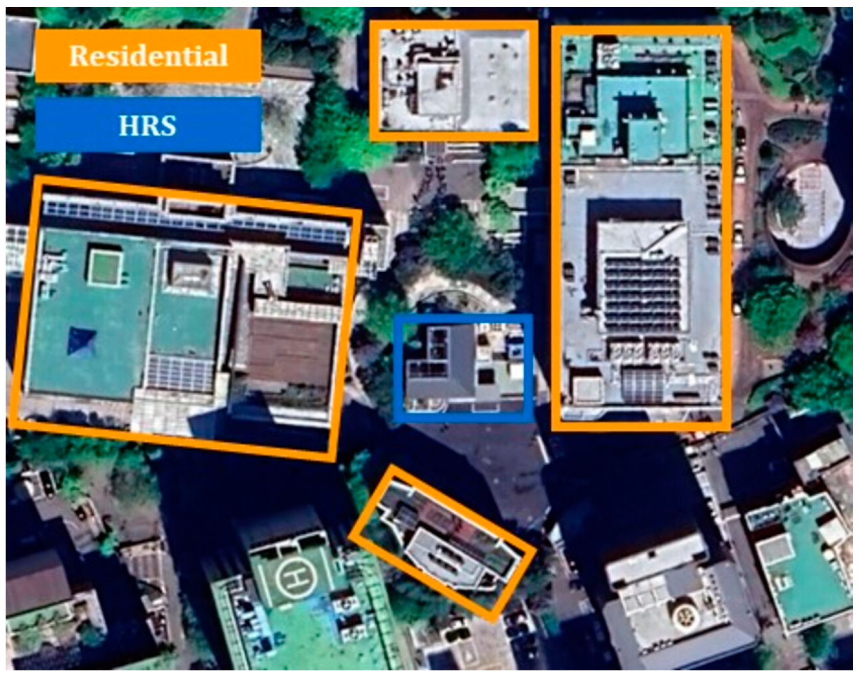
Figure 1. Satellite picture of Seosomun HRS and surrounding buildings.
Energies 17 00867 g001
Figure 2. PFD of Seosomun HRS.
Energies 17 00867 g002
Figure 3. Overpressure for scaled distance for peak side on overpressure [32].
Energies 17 00867 g003
Figure 4. IR without shutoff valve system: (a) Outdoor IR; (b) Indoor IR.
Energies 17 00867 g004
Figure 5. IR with single shutoff valve system: (a) Outdoor IR; (b) Indoor IR.
Energies 17 00867 g005
Figure 6. IR with dual shutoff valve system: (a) Outdoor IR; (b) Indoor IR.
Energies 17 00867 g006
Figure 7. Comparison of FN curves based on the application of a shutoff valve.
Energies 17 00867 g007
Table 1. Operating conditions for Seosomun HRS [21,22].
FacilityOperating Pressure
(bar)
Operating Temperature
(°C)
Storage Mass
(kg)
High-pressure
storage tank
8702172.6
Medium-pressure
storage tank
6302185.7
Tube trailer20021200
Table 2. Accident scenarios of HRS [10,23].
FacilityAccident ScenarioLeak Diameter
(mm)
Leakage Frequency
( y r 1 )
High-pressure
storage tank
Catastrophic rupture-5.00 × 10⁻⁷
Large leak7.161.02 × 10−4
Medium leak2.262.09 × 10−4
Small leak0.721.23 × 10−3
Medium-pressure
storage tank
Catastrophic rupture-5.00 × 10⁻⁷
Large leak7.921.02 × 10−4
Medium leak2.502.09 × 10−4
Small leak0.791.23 × 10−3
Tube trailerCatastrophic rupture-5.00 × 10⁻⁷
Large leak12.701.80 × 10−4
Medium leak4.023.21 × 10−4
Small leak1.274.14 × 10−4
Table 3. Leakage probability of gas station [12].
FacilityAccident ScenarioLeak Diameter
(mm)
Leakage Frequency
( y r 1 )
Pressurized vesselCatastrophic ruptureover 152.46.00 × 10−7
Large leak101.62.00 × 10−6
Medium leak25.42.00 × 10−5
Small leak6.48.00 × 10−6
Atmospheric tankCatastrophic ruptureover 152.41.00 × 10−7
Large leak101.65.00 × 10−6
Medium leak25.42.50 × 10−5
Small leak6.47.00 × 10−5
Pipe (8 to 16 inch)Catastrophic ruptureover 152.46.00 × 10−7
Large leak101.62.00 × 10−6
Medium leak25.42.00 × 10−5
Small leak6.48.00 × 10−6
Table 4. Worst case weather conditions [24].
Weather
Conditions
Wind SpeedAtmospheric
Temperature
Atmospheric
Stability
Humidity
Worst case1.5 m/s25 °CF50%
Table 5. Population of HRS and surrounding buildings [22,25].
BuildingsPopulation CategoryDay
Population
Night
Population
Indoor Fraction
Seosomun HRSOperator2 (Resident)
2 (Non-resident)
2 (Resident)0.9
Seosomun Government Complex 2Public9500.9
Seosomun Annex Building 513300.9
Parliamentary Hall8600.9
Seosomun Welfare19500.9
Seoul Museum of ArtPublic175
(1746/10 h *)
00.9
Total-6882-
* Weekday operating time = 10 h.
Table 6. Fraction of day and night.
TimeTime PeriodFraction
Day09:00~20:00
(11 h)
0.4583
Night20:00~09:00
(12 h)
0.5417
Table 7. Failure probabilities and operating times of the valves [18,27,28,29].
ValveFailure Probability ( y r 1 )Operating Time (Seconds)
Check valve0.0009 0
Excess flow valve0.00090.1
Shutoff valve0.11 30
Table 8. Damage of radiation heat on humans [38,39].
Radiation Heat
(kW/m2)
Damage on Humans
4Pain and swelling occur if not protected for more than 20 s
12.5Fatalities occur within minutes
37.5Instant death
Table 9. Damage of overpressure on humans [40].
Overpressure
(psi)
Damage on Humans
1Ruptured eardrum
3Physical injury may occur
5Risk of injury and even a possibility of death
Table 10. Ignition probabilities for hydrogen [10].
Release Rate
(kg/s)
Ignition Probability
ImmediateDelayed
<0.1250.0080.004
0.125−6.250.0530.027
>6.250.2300.120
Table 11. Peak release rate for target HRS facility.
FacilityPeak Release Rate (kg/s)
Large LeakMedium LeakSmall Leak
High-pressure
storage tank
1.630.160.02
Medium-pressure
storage tank
1.500.150.02
Tube trailer1.320.130.01
Table 12. Radiation heat data of jet fire in leak scenario.
FacilityLeak SizeFlame Length
(m)
Distance Downwind to
Radiation Heat (kW/m2)
412.537.5
High-pressure
storage tank
Large21.0734.2825.9521.28
Medium7.3211.198.526.81
Small2.533.28--
Medium-pressure storage tankLarge20.5333.5725.3420.74
Medium7.1410.928.306.61
Small2.453.16--
Tube trailerLarge19.8833.2224.9720.29
Medium6.9510.858.196.49
Small2.393.15--
Table 13. Overpressure data of VCE in leak scenario.
FacilityLeak SizeExplosion Center
(m)
Diameter of Overpressure (psi)
135
High-pressure
storage tank
Large4035.5515.2411.05
Medium208.033.442.50
Medium-pressure storage tankLarge4034.9915.0010.88
Medium107.503.212.33
Tube trailerLarge4033.3614.3010.37
Medium107.253.112.25
Table 14. Radiation heat data of fireball in catastrophic scenario.
FacilityFireball Diameter (m)Radiation Heat
Level (kW/m2)Diameter (m)
High-pressure storage tank12.104100.24
12.557.58
37.533.02
Medium-pressure storage tank12.794105.58
12.560.91
37.534.80
Tube trailer16.964137.87
12.580.37
37.545.48
Table 15. Overpressure data of VCE in catastrophic scenario.
FacilityExplosion Center (m)Overpressure
Level (psi)Diameter (m)
High-pressure
storage tank
10181.69
335.20
525.33
Medium-pressure storage tank10186.96
337.24
529.85
Tube trailer201113.18
347.13
534.38
Table 16. IR data for each case.
CaseFacility Risk   ( y r 1 )Percentage (%)
Without
shutoff valve
HP Storage tank1.67 × 10−526.72
MP Storage tank1.63 × 10−526.17
Tube trailer2.93 × 10−547.11
Total6.24 × 10−5100.00
With single shutoff valveHP Storage tank1.82 × 10−626.77
MP Storage tank1.78 × 10−626.13
Tube trailer3.20 × 10−647.10
Total6.80 × 10−6100.00
With dual
shutoff valve
HP Storage tank2.00 × 10−726.77
MP Storage tank1.96 × 10−726.13
Tube trailer3.52 × 10−747.10
Total7.48 × 10−7100.00
Table 17. IR of operator and public.
CaseGroupTotal Risk Integral
Without shutoff valve Operator6.16 × 10−5
Public7.91 × 10−7
With single shutoff valveOperator6.75 × 10−6
Public5.21 × 10−8
With dual shutoff valveOperator7.43 × 10−7
Public5.73 × 10−9
Disclaimer/Publisher’s Note: The statements, opinions and data contained in all publications are solely those of the individual author(s) and contributor(s) and not of MDPI and/or the editor(s). MDPI and/or the editor(s) disclaim responsibility for any injury to people or property resulting from any ideas, methods, instructions or products referred to in the content.