1. Introduction
In modern sensing techniques, Magnetic Fields (MFs) can be utilized in various industries. Contactless magnetic sensors, for instance, leverage MFs to measure electrical currents, while requiring no direct physical contact with the electrical conductor. By reducing wear and tear effects from the electrical conductors, such sensors can be implemented in ample processes, in a wide range of fields, ranging from industrial automation and automotive industry to smart grid applications [
1]. Therefore, magnetic data acquisition using magnetic-based sensors makes the latent invaluable in applications where the traditional sensors (i.e., invasive electrical sensors) are not practical, such as drone and Unmanned Aerial System (UAS)-based applications for Transmission Line (TL) monitoring applications.
For contactless current sensing processes driven by UAS, as an example, MFs provide a clear and accurate image reflection of the current flowing through the electrical TLs; the directly proportional generated magnetic field around the TL, induced by the current, allows for a straightforward correlation between the field’s strength and the current’s amplitude. Accordingly, real-time insights over the status of the TL can be gained, which are essential for preventing overloads, power distribution optimization, and ensuring the electrical grid’s reliability [
2].
In order to know the mechanism through which MFs serve as a data source for magnetic-based electrical sensors, these sensors’ principles of operation must be first known. Existing in various types, the following set represents some of the working principles of magnetic-based electrical sensors:
Hall effect sensors [
3]: the generation of a voltage across a conductor when subjected to an MF represents the Hall effect. Hall sensors mainly consist of a thin semiconductor plate. The application of an MF perpendicularly to the plate deflects the charge carriers. Such deflection in turn creates a voltage difference across the plate. This resultant voltage is proportional to the norm of the applied MF, which is, in turn, proportional to the strength of the conductor’s current.
Ampere’s law-based sensors [
4]: these sensors correspond generally to coils with a fixed geometry, to be wrapped around the TL. The MF generated by the currents passing through the TL either induces a voltage or changes some properties of such sensors’ constitutional materials. The electrical detection of these changes can provide information about the current. The Rogowski coil is an example of an Ampere’s law-based sensor, where it measures the MF’s time rate change, then converts it into an electrical signal, in order to determine the current.
Magneto Resistive sensors [
5]: these sensors utilize certain materials with a “magnetoresistance” property. Such materials have their electrical resistance changing when exposed to a MF and constitute different types of Magneto Resistive sensors, such as Anisotropic Magnetoresistance (AMR) [
6], Giant Magnetoresistance (GMR) [
7], and Tunneling Magnetoresistance (TMR) [
8]. AMR, for instance, has its resistance varied based on the angle between the applied MF and the material’s magnetization. GMR sensors, on the other hand, rely on the relative orientation of the MFs. Lastly, TMR sensors utilize the phenomenon of electron tunneling, taking place when electrons pass through an insulating layer amid two magnetic layers. The insulating layer’s resistivity is heavily influenced by the relative orientation of the magnetic moments in the adjacent layers. With the parallel/anti-parallel alignments of magnetic moments, electrons tunnel more easily/harder, thus resulting in lower/higher resistances of the insulating layer, respectively. This change in resistance allows for the detection of the inducing external MF, thus proportionally measuring the electrical current behind its existence.
Therefore, the magnetic-based sensors fed by the data carried by MFs ameliorate the safety and reliability within electrical systems. First of all, the actual MF surrounding TLs clearly provides an overview of the grid’s health. By monitoring these MFs and through the set of magnetic-based sensors listed above, better decision-making and more robust preventive maintenance schemes can be established for electric grids [
9]. The valuable insights into the current’s behavior, for example monitored using magnetic-based sensors, enables the identification of potential issues, like overloads and even faults. With such a proactive approach, the TL’s reliability can be significantly improved, where the risks of unexpected failures would also be minimized. It can be also stated that the contactless TLs’ monitoring process, helps in optimizing the grid’s performance (due to the reduced faults) and overall efficiency (better load equilibration), contributing hence to a more secure and stable electrical infrastructure [
10].
Such added values over an electric grid (i.e., improved preventive maintenance, better status acknowledgment, etc.) exist only with proper numerical analyses of MFs, which constitute the informative background for contactless sensors. In other terms, the enhanced grid management is feasible by means of data harnessing from MFs. On the first hand, MFs’ numerical analyses enable the real-time monitoring and assessment of the grid’s condition. Such data, when leveraged by smart grids’ utilities, compose a background for knowing the root cause behind power fluctuations, power quality issues, and potential faults [
11]. With such a gained capability, self-healing ability within the grid is optimized, as power rerouting would be better actuated, hence automatically minimizing disruptions and enabling better energy optimization. Additionally, the better understanding of the generated MFs around the TLs allows for better cooperation between smart grids and renewable energy resources [
12], since electric grids would have a dynamical adaptation to variable generation patterns. Moreover, with the improved preventive, as well as predictive, maintenance schemes, added by the insights from MFs’ numerical analyses, the grid’s downtime can be reduced, thus lowering different maintenance costs and enhancing the demand-side management.
Even though the stated MF analysis is fruitful in terms of physical data acknowledgment for contactless sensors with the positive subsequent consequences (i.e., better monitoring, lower blackouts, etc.), still, MF calculations can be a challenging task, especially for the case of stranded (twisted) TL architectures. Due to the fact that an MF is a vector quantity, having magnitude and direction, physical laws (e.g., Ampere’s law, Biot–Savart law, etc.) must be applied in order to determine its norm. Such computations, which involve integral calculus, are not straight-forward, particularly for TLs that are composed of multiple sub-filaments and of non-trivial geometries. For a stranded TL, each of the strands carries a portion of the total current, with a specific amplitude and vector orientation for the induced MF. Accordingly, the MF’s calculation is complicated due to the varied positions and orientations of each individual strand. With that being said, the Biot–Savart law for a straight current-carrying conductor cannot give the picture of the total generated MF in this case. Instead, the resulting MF calculation requires breaking down the wire into infinitesimally small current elements. To evaluate the contributions from all elements, the superposition principle must in turn be employed to sum up the MF generated by each element, where additionally the magnetic interactions between the strands must be also taken into consideration. This means that the larger the set of current elements exist, the longer the calculation time is required in order to produce an accurate MF estimation. This adds cumbersomeness over the entire process, notably with non-uniform current distributions [
13], where the calculation must involve, as input factors, the distances between the strands, the number of strands, and each individual current values. Along with the mathematical complexity for calculating the produced MFs around TLs, manual calculations have extremely limited accuracy and do not converge towards a real solution. For instance, when performing these computations by hand, challenges arise from the point where the three-dimensional structures of TLs must be considered. Additionally, real-world stranded TLs may involve hundreds of individual strands, thus making a precise MF calculation impossible. For a proper contactless electrical sensor design, with a basis on MF calculation, these challenges can be overcome by means of numerical simulations in specialized software, to have an accurate image for the accurate MFs around real TLs.
Automated numerical methods, on the other hand (i.e., by means of computerized software), are good for reducing the manual complexities in calculating the current resulting MFs around stranded TLs. By employing different workflow structures, such numerical techniques help in giving a clear idea about the actual MFs around TLs, where some of them are listed as below:
Finite Difference Method (FDM) [
14]: the FDM discretizes a space (i.e., stranded TL) into a grid, in which the partial differential equations (governing the MFs) are numerically and iteratively solved. While the FDM is easy to implement and suitable for time-dependent problems and can handle complex equations and boundary problems, it reflects on the other side an inefficiency to compute MFs for complex geometries (e.g., a stranded TL with tens of strands).
Finite Volume Method (FVM) [
15]: With the FVM, the space to be studied is divided into volumes, where the fluxes across the faces of these volumes are computed. Even though the FVM conserves the physical properties of the space well, in addition to its suitability for irregular grid geometries, it can be computationally exhaustive for some structures (i.e., strands excessively overlapping across a finite TL’s length).
Boundary Element Method (BEM) [
16]: by discretizing only the boundaries of a problem, the BEM reduces the number of unknowns, thus providing extra particularity for unbounded domains. On the other hand, this method’s accuracy is highly affected by singularities.
Method of Moments (MoM) [
17]: the MoM represents a numerical technique that discretizes the surfaces of objects into smaller elements. It is mainly used for the electromagnetic behavior of antennas and less used for analyzing the MFs of TLs.
Finite Integration Technique (FIT) [
18]: this technique combines both FDM and FVM and yields in discretizing both space and time. The FIT is suitable for solving Maxwell’s equations in electromagnetics, including MFs simulation, which makes it good for the purpose of TL monitoring. It, however, presents high complexity upon applications.
Homogenization and the Cauer ladder method [
19]: in this modern technique, stranded electrical wires are modelled via approximated numerical computations with the Cauer ladder network; 3D MFs are hence calculated and projected to a 3D geometry so that any stranded TL configuration can be simulated with a current vector potential and a homogenized conductivity at each time step.
Aside from the different surveyed numerical techniques that are used to evaluate the MFs generated by currents in stranded TLs, the Finite-Element-Analysis (FEA) [
20] based technique is another powerful computational method. The FEA divides a complex physical structure (i.e., a stranded TL with too many strands) into smaller and simpler elements. At the level of each element, a mathematical model (representing a set of equations) is used to model its behavior. The collective solving for all elements yields, eventually, the prediction of the entire structure’s overall behavior (i.e., the resulting MFs around the studied TL when injected with a current of a known amplitude). With that being said, the FEA-based computational techniques are more suitable for various physics and structures, can handle complex geometries more efficiently, and are able to accurately reflect the numerical results of different computations into graphical outputs. As compared to the other numerical methods, FEA enables better resolution in the region of interest (i.e., each filament composing a stranded TL) by allowing for adaptive mesh refinement. Additionally, tiny fragments within each filament can be better represented by means of higher-order elements, in parallel to incorporating material properties (i.e., copper, aluminum, etc.) more easily. Due to these mentioned reasons, in addition to supporting a mixed element (i.e., copper and aluminum inside the same transmission line) formulation and its consistency in handling boundary conditions, the FEA approach is chosen in this study.
Accordingly, this paper aims to utilize the COMSOL Multiphysics 6.1 software [
21], which is based on the FEA, in order to simulate and visualize the resulting MFs around stranded electrical TLs, when subjected to different currents. This is established in order to have discrete values (with as much as possible high accuracy) of the actual MFs around actual TLs, thus consisting of a reference for the magnetic-based sensor (i.e., TMR) sensitivity, to be employed in a drone-based remote monitoring process for TLs. In other terms, the tabulated data involving the number of filaments, the magnitude of the injected currents, and the magnitude of the resulting magnetic fields with respect to the distance from the TLs is to be presented. The latent shall compose a background for choosing magnetic-based sensors intended to sense the current in TLs, non-invasively. The magnetic-based sensors (i.e., TMR) are to be installed in a UAS application according to the “Digitalisierte, rechtssichere und emissionsarme flugmobile Inspektion und Netzdatenerfassung mit automatisierten Drohnen” (DNeD) project description [
22], hence ensuring an accurate current sensing process by means of a drone-based application.
The remainder of this paper is composed as follows:
Section 2 presents the working methodology behind the fabrication of this paper.
Section 3 represents the mathematical model that is needed for MF calculations.
Section 4 outputs the COMSOL simulation of MFs resulting from a single straight current-carrying conductor.
Section 5 reveals the construction for different stranded wires’ Computer Aided Design (CAD) models in COMSOL.
Section 6 provides the outcomes of all simulation results for each of the designed TL architectures.
Section 7 exposes the discussion over the attained results and considers the TMR application in the sensor’s box of the DNeD’s drone. Finally, conclusions are derived in
Section 8.
2. Research Methodology
With the stated advantages of FEA over other similar numerical methods, the COMSOL simulation conducted in this paper starts by classifying the TLs’ geometries, mainly with respect to the number of filaments. According to the regulation EN 50182:2001(D) the reference [
23], the intended TL geometries to be analyzed are of 7 filaments, 19 filaments, 37 filaments, 61 filaments, and 91 filaments, as revealed with their other characteristics as in the norm EN 50182:2001(D). It is worth mentioning that despite having no direct effect between the TLs’ materials and the MF’s norm, still, the study is conducted with exact similarity as in reference [
23]. Accordingly, some of the materials in the norm EN 50182:2001(D) represent Aluminum (AL1), Aluminum alloy (AL3), and galvanized steel wire (ST1A).
The collection of overhead TLs’ characteristics of the norm EN 50182:2001(D) was chosen for simulation purposes only, where in reality, they are actually used for power transmission in certain European countries. The AL3, for instance, represents alloyed Aluminum with other materials as a way to improve the TL’s mechanical properties and electrical conductivity. Moreover, some filaments of the stranded TL, as depicted in the norm EN 50182:2001(D), are made of galvanized steel encircled with others from the same TL, made of Aluminum. This configuration can be interpreted as a trade-off between corrosion resistance and maintained electrical conductivity. The Zinc layer coating the steel provides excellent corrosion resistance, acting as a sacrificial anode; it corrodes preferentially, thus protecting the underlying steel. Therefore, some of the norm EN 50182:2001(D) characteristics, for the TLs of 37 and 61 filaments, representing a mixed architecture of different materials (Aluminum and galvanized steel), help in making the entire TL more flexible in front of challenging environmental conditions.
For all TLs ranging from 7 filaments to 91 filaments, each filament is represented by a “sweeping” cylinder around the neighboring filament. Additionally, for each TL, a feeding current of a value between its maximum/minimum margins will be injected from a defined common starting node, in order to finally visualize and interpret the total resulting MF. Thereafter, tabulated data encapsulating the number of filaments, the magnitude of the injected currents, and the magnitude of the resulting magnetic field with respect to the distance from the TL are to be presented. The final tabulated data would serve as a background for choosing magnetic-based electrical sensors, which are intended to sense the actual currents in overhead TLs, non-invasively. The suggested magnetic sensors with their corresponding sensitivity are to be then investigated for installation in a UAS process (according to the DNeD’s project description).
Eventually, the numerical tabulated data, outputted from this study, would ensure accurate current sensing processes by means of a drone-based application. By taking into consideration this described workflow, and with consideration of the statute presented in the norm EN 50182:2001(D), the sequential steps for obtaining MFs’ related graphics in COMSOL can be elaborated as follows with four main steps:
Building the geometry: this step defines the geometric parameters and the object’s (i.e., TL) characteristics intended to be simulated. Whether the TL is to be drawn in 2D or 3D spaces, its dimensions, boundaries, curvatures, and every detail related to its body construction are to be specified. Moreover, for the intended MFs in the study, during this step, the boundary conditions must also be defined. This urge arises from the fact that MFs are not generally compressed by obstacles in nature and therefore must be virtually limited by boundaries in COMSOL, in order to study their interactions at defined points with respect to the TL.
Selecting the materials: according to the norm EN 50182:2001(D), the TL can encounter filaments with mixed or different materials. For this, each filament must have its material registered in the project’s workflow. For the case of TLs having 37 and 61 filaments and since the galvanized steel-based filaments are added to make the entire TL more immune to undesired environmental conditions, it must be specified, technically, which actual filaments are of ST1A and which others are made from AL1 and AL3. Different materials embed specific electrical properties (e.g., conductivity, resistivity, etc.), as well as mechanical characteristics (e.g., stress, elasticity, etc.). It is therefore crucial to determine the materials of each filament specifically as in the norm EN 50182:2001(D).
Mesh generation: after creating the geometry and assigning different materials for different composers (in this case, the filaments), the meshing process sequentially divides the entire geometric model into smaller elements to enable the numerical simulation (i.e., application of FEA). It hence composes the basis for solving the system’s (i.e., TL with virtual boundaries) differential equations and understanding the system’s behavior under various physical conditions (i.e., different norms for the injected current). The infinitesimal elements are then connected with a network of nodes, which yields a single output (i.e., MF’s norm). The better designed the mesh quality is, the better the accuracy and convergence in the final solution, but on the other hand, larger computational power is needed. The methodology of meshing in this study is based on a trade-off between finer mesh qualities and good convergent output, with as minimum as possible computational time and resources.
Solver selection: the mathematical equations that represent the physical behavior of each element are solved iteratively using numerical methods. The mathematical model in this case can be represented by Maxwell’s equations and could be solved via the “coil geometry analysis” in COMSOL.
The completion of these four main tasks finally allows the model to be post-processed in COMSOL and the outputs to be visualized in both numerical, as well as graphical, forms. Each of the suggested TLs’ architectures is to be presented in a 3D mode, where it would be possible to visualize and interpret the resulting MF’s norm at any point
in the space of the TL, under the created virtual boundaries. These four steps, in addition to their anticipated MF for each TL’s architecture, can be summarized graphically as in
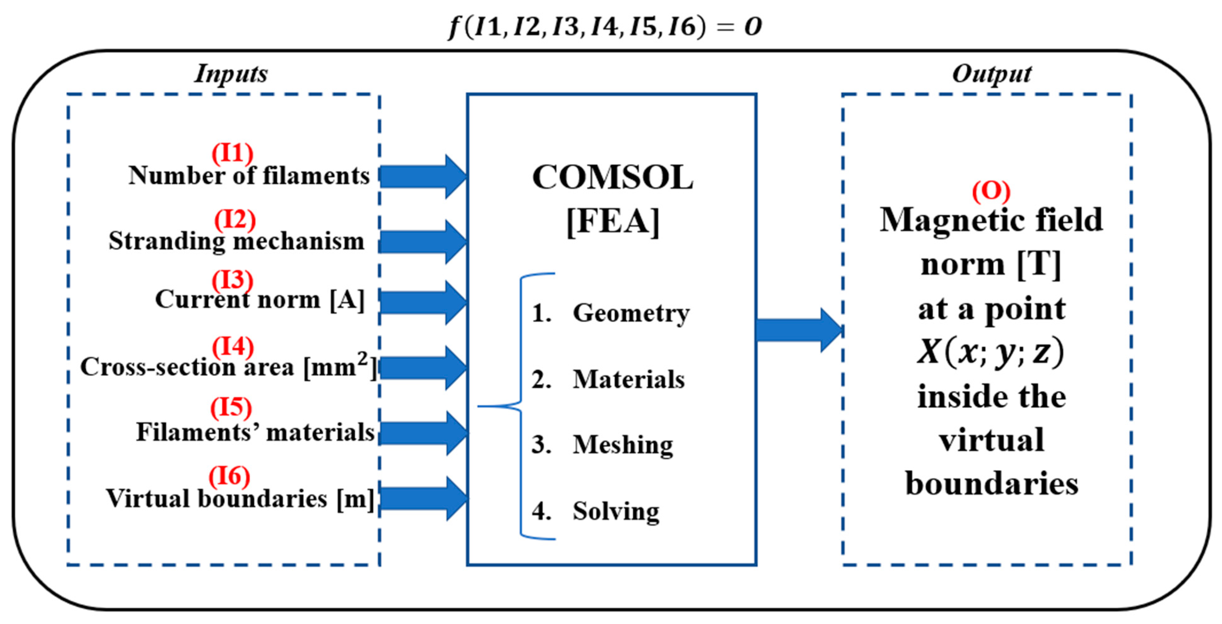
Figure 1: for each TL, the standard workflow in this study is to obtain a function-like input/output relationship where the inputs for each TL are as listed in
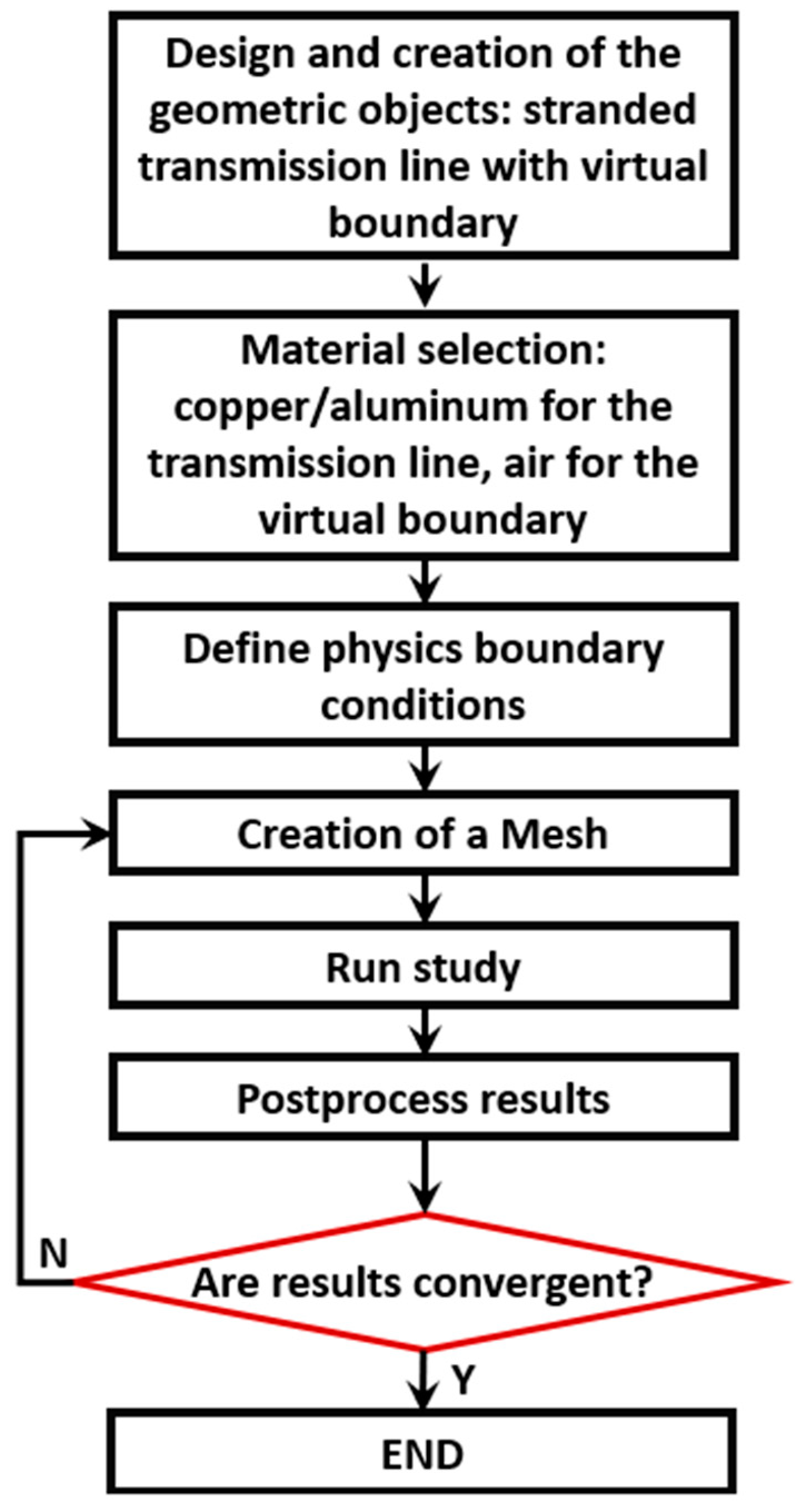
Figure 1, ranging from I1 (Input 1) to I6. The overall flowchart behind this approach is presented in
Figure 2. The required output always corresponds to the MF’s norm at point
in the space of the virtual boundary. For different positions around the TL for each case of the study (i.e., different coordinates of
), a specific MF exists, where at the end, the minimum/maximum MF’s norms can be known from a minimum/maximum distance from the TL. Therefore, accurate knowledge in defining the required magnetic-based sensor for the drone-based TL monitoring will be attained.
As can be stated from the observation of
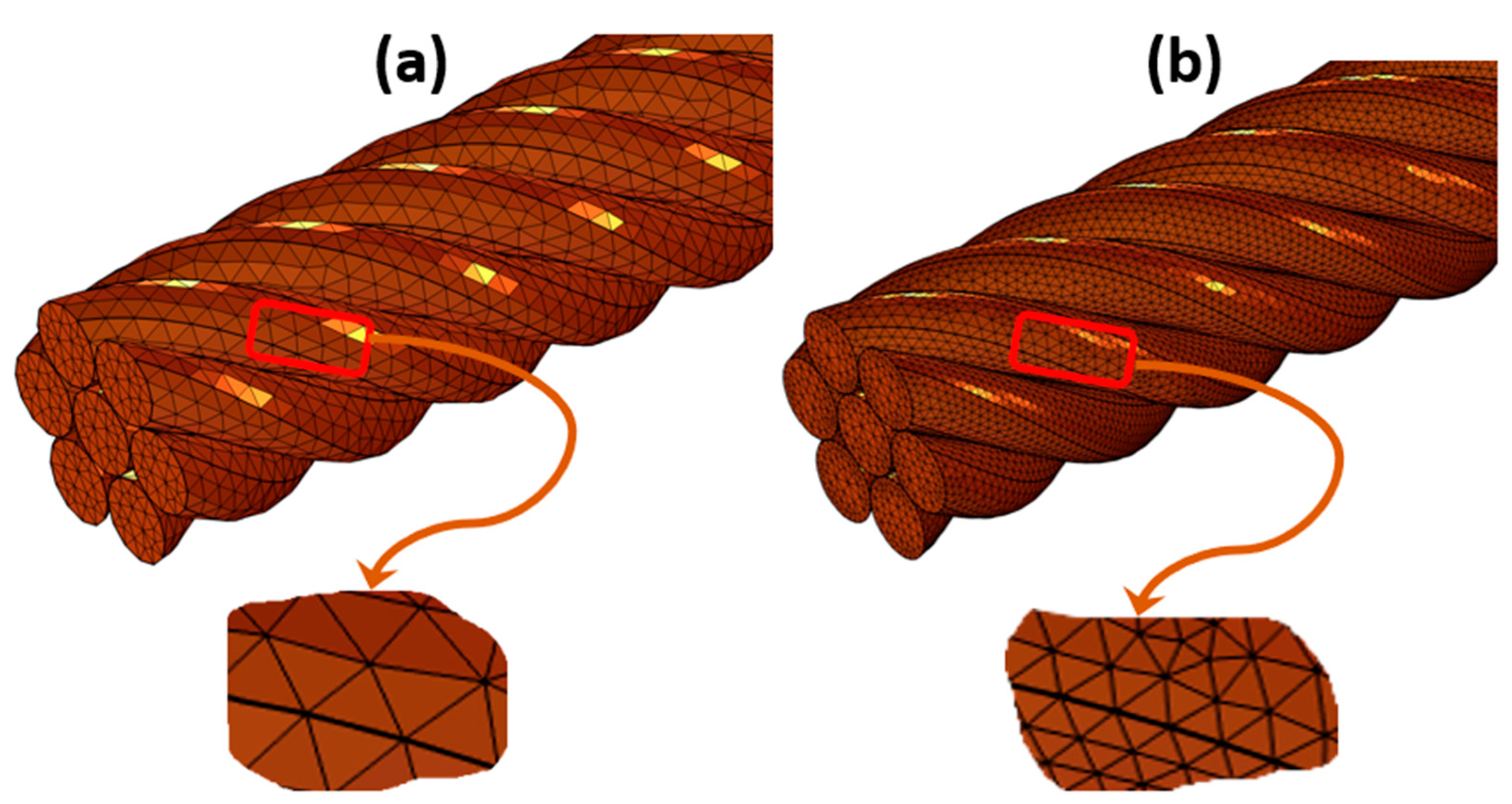
Figure 2, one of the most important tasks within the shown flowchart is the mesh generation. The results’ convergence test is hence mainly dependent on the conducted mesh’s quality. In other words, the MFs’ norms are regarded as conclusive values, only if the mesh was fine enough. When the mesh is more fine while noticing that the MFs’ norms are not changing, this means that the last obtained mesh was the optimum. One can directly use an extremely fine mesh for example, but again, this would require huge computational time. An extreme coarse mesh, on the other hand, would develop non-convergent MFs’ norms, despite the fast computational speed. Accordingly, an adaptive meshing technique was conducted in this study, which dynamically refines or coarsens the mesh based on the solution behavior and the overall visualization of the MFs around the stranded TLs. All meshes are built using tetrahedral-based elements.
Figure 3 encapsulates the startup mesh and the final adapted mesh for the 7-filament TL, after manual refinement and analysis with respect to the MFs’ norm values.
3. Mathematical Model
The stranded TLs’ architectures must be assigned to a numerical solver in COMSOL (after completing the geometries and assigning meshes). This solver in turn, by means of several iterations with respect to a defined threshold, tests the obtained solution for convergence. In other terms, it numerically computes a reference mathematical model, over which the MF creation due to the passage of currents in the TLs underlies. Generally, the concept behind such a model in the current study is Ampere’s law, which represents a subset of the Maxwell’s equations [
24].
Ampere’s law relates the magnetic field around a closed loop to the current passing through the surface, bounded by that loop, as can be deduced from its mathematical formulation (vector notation) in (1).
such that
represents the magnetic field vector,
an infinitesimal length vector along the closed loop path,
the free space’s permeability,
the current density vector,
an infinitesimal area vector, and
the total electric current passing through the loop [
24]. Accordingly, Ampere’s law, with its mathematical form in (1), provides a general framework for calculating MFs, advantageously when there is a symmetrical current distribution, and for the cases with geometrical symmetry in the MF-radiating object. As a specific case of the described Ampere’s law, the Biot–Savart law [
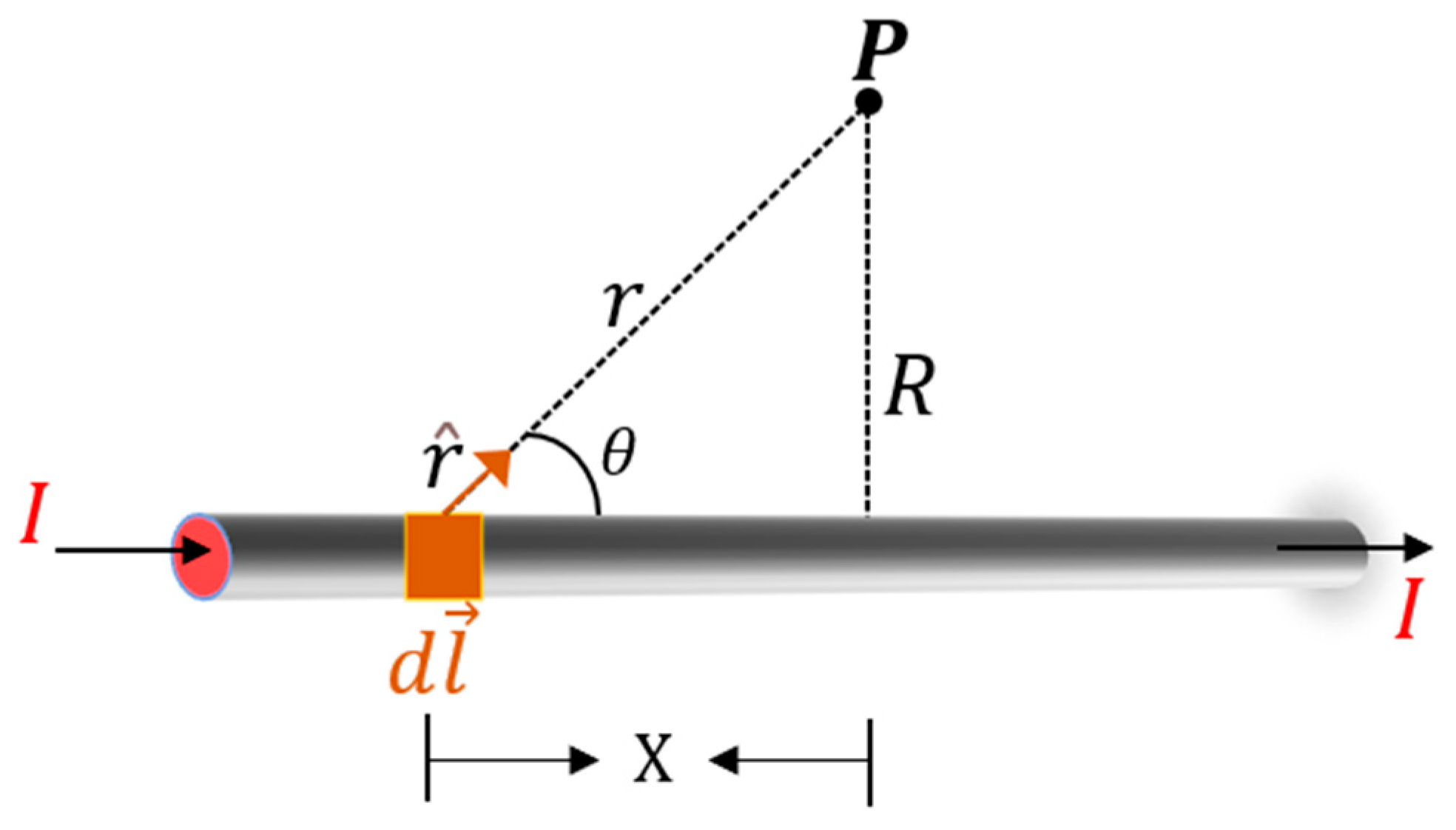
24], expressed in (2), also describes the MF produced by a continuous current distribution: the magnetic field at a point in space is calculated due to an infinitesimally small current’s segment, as presented in
Figure 4. The Biot–Savart law hence allows for specialized solutions for cases involving complex current distributions. Both laws constitute the mathematical background for solving the MF values at specified distances from the designed TLs.
such that
represents the MF,
the free-space permeability,
the current (root cause of the MF creation),
the infinitesimal wire segment,
a unit vector that points from
to the point in space (around the TL) on which the MF is to be measured, and
the distance from
to the point of measurement in space [
24].
The point P in
Figure 4 is the point in space, around the TL, at which the MF resulting from the passage of I in the grey conductor is intended to be acknowledged. The vertical projection of P on the x-axis is separated by a distance
X from
. The cross-product of
points out of the page for all elements along the wire (right-hand rule). Therefore, the MFs due to all current elements have the same direction at point P. Accordingly, the stated cross-multiplication becomes equal to
. From another side, the distance
from
to P can be calculated by means of the Pythagoras theorem as expressed in (3), where in (4) presented it is the relationship between
and
.
By utilizing the integral form of (2), as presented in (5), and substituting (3) and (4) into (5) while taking into consideration that the grey wire (TL) of
Figure 4 stretches from the origin of the plane towards positive infinity, the numerical value of the produced MF is shown in (6).
The result in (6) is intended to be achieved for a stranded TL, instead of a single straight TL, as shown in
Figure 4, which takes into consideration the crossing between the filaments and the resulting directions of the resulting MF for each filament. The inversely proportional relationship between the resulting MF norm and the distance
as exposed in (6) is to be noted; from this point, the effects of the neighboring TLs, to the TL over which the sensor box will be dropped (i.e., DNeD’s project workflow), will be considered negligeable. This is because
(between the neighboring TLs over the transmission tower and point P in space) will be relative in meters, having thus no effects over the MF generated by the TL under investigation, which has the TMR sensors to be installed around, in the range of centimeters.
4. MF Visualization in COMSOL: Single Conductor
The first approach in visualizing the MF created by the current flow in a TL, is to apply the mathematical model presented in
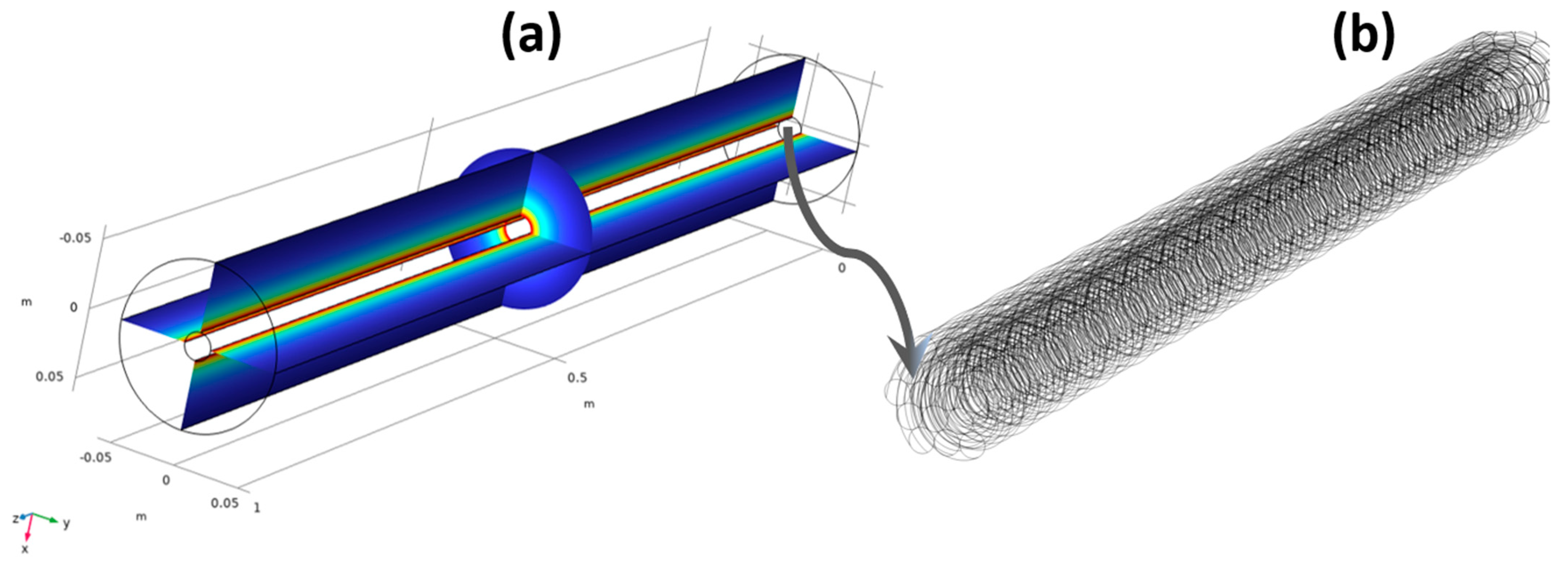
Section 3. A single straight “cylinder” will be denoting the electrical conductor (i.e., TL). This cylinder shall be enclosed under another cylinder, representing, in turn, the virtual boundary. The cylinder representing the wire has a diameter of 0.01 m, where the cylinder representing the virtual boundary has a diameter of 0.06 m. The electrical conductor is made of copper, where the virtual boundary is made of air. By injecting the designed single straight TL with a current amplitude of 100 A, the MF radiation around it under the virtual boundary will have the representation as in
Figure 5a. The resulting MF is shown in both the x-plane and y-plane, where it can be obviously concluded how it diminishes as the distance from the TL gets bigger. From the results of
Figure 5a and with 100 A of current as an example, the choice of TMR sensors can be investigated, with a maximum distance from the TL equal to or less than 0.05 m.
Table 1 represents the consequently different norms of the resulting MF, at different points
around the TL.
The different points in space shown in
Table 1 were chosen randomly for simulation purposes only. The resulting MF norms reflect the application of the mathematical model in
Section 3, for each calculation. It is worth mentioning that the z-coordinates have the biggest values among other coordinates since they represent the positioning around the TL’s space with respect to its length (i.e., a portion of 1 m from the total infinitely long current-carrying conductor is shown in
Figure 5a). In other terms, a z-coordinate with a value of 1 m indicates that the point in space thereof is at the wire’s extremity (i.e., maximum length). As the opposite, both x and y coordinates are encapsulated by the virtual boundary with a radius of 0.06 m. As can be stated from
Table 1 and in conjunction with (5) and (6), the resulting MF norm diminishes with respect to the increased distance from the TL. Moreover, the x-plane- and y-plane-based representation of the MF in
Figure 5a is for demonstration purposes of the MF norm, where in reality, the actual resulting MF is created in all directions, without a reference towards any plane, as shown in
Figure 5a. When it is straightforward to compute the resulting MF around the straight conductor shown in
Figure 5a (i.e., simple application of Biot–Savart law), the complexities arise when the cylinder of
Figure 5a is replaced by a stranded wire, as shown in
Figure 5b. The arrow representation in
Figure 6 represents the actual MF norm with its corresponding orientation in all directions (hence the applicability of TMRs anywhere in the space under the virtual boundary limits) where bigger arrows (closer to the TL) denote larger MF norms. Under all cases and with respect to the geometry/size of the virtual boundary, it can be stated that a TMR with a sensitivity in the range of 0 to 2 mT is optimal for the application to sense the resulting MF due to the passage of 100 A in the straight TL. Despite representing a direct application of the mathematical model of
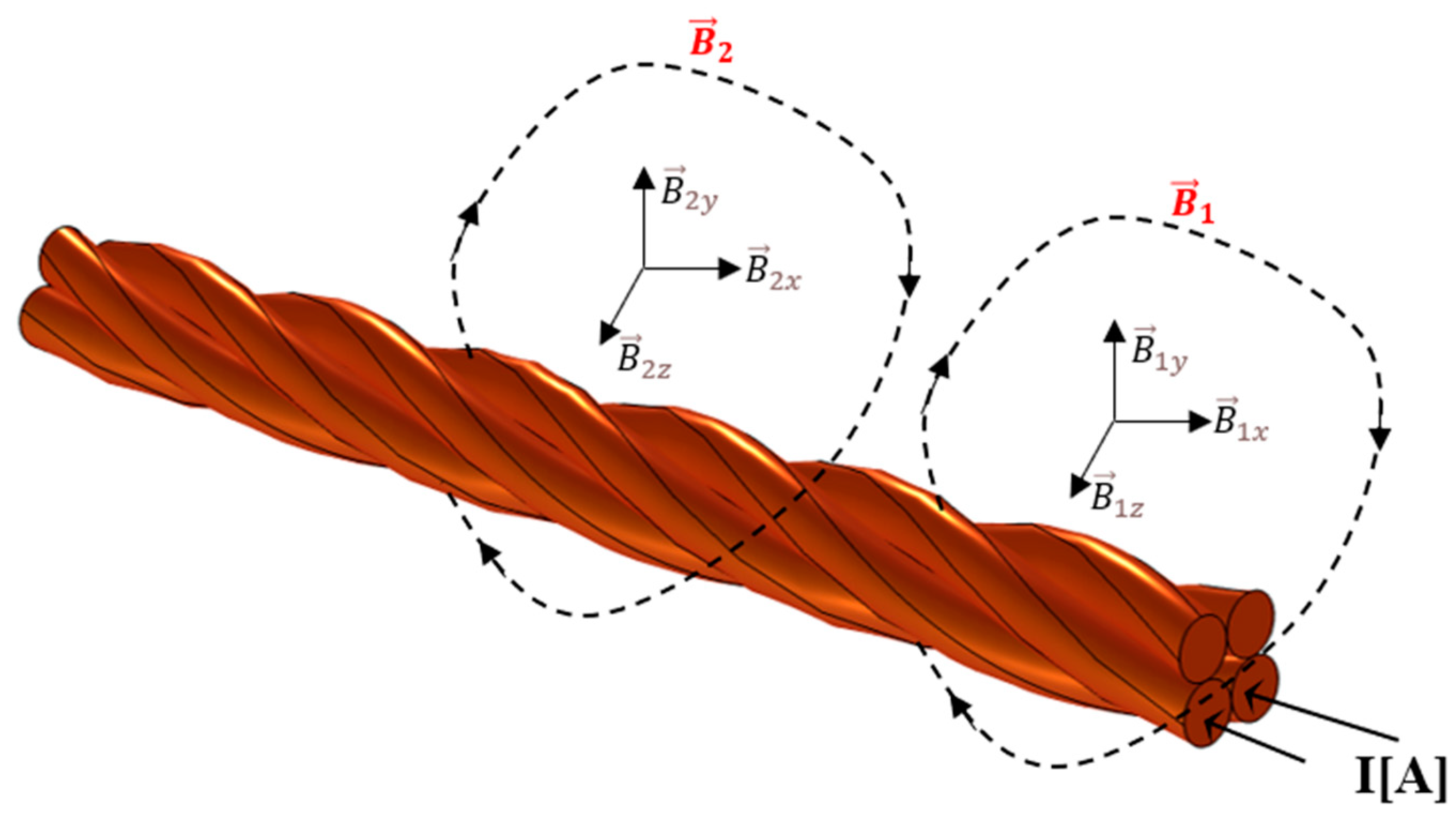
Section 3, the same MF calculation procedure and by taking into consideration the MF’s vectorial superposition, gets harder for a stranded TL, as represented in
Figure 7. The four-filament TL shown in
Figure 7, would radiate an MF originated from each filament. As an example, when a current flows into the bottom two filaments, two MFs are created and denoted as
and
. Therefore, the total radiated MF will be the vectorial sum of each effector MF (in amplitude and direction). Accordingly, the larger number of filaments indicates a larger resultant overall MF, which is intolerable to a manual calculation (i.e., to decompose each filament into infinitesimal current elements, calculate the emitted MF of each, vectorially superimpose each MF with the others, etc.). Hence, for the intended TLs to be simulated, as indicated in the norm EN 50182:2001(D), it becomes more and more challenging to define an accurate resulting MF for each.
5. Stranded TLs: CAD and Meshes
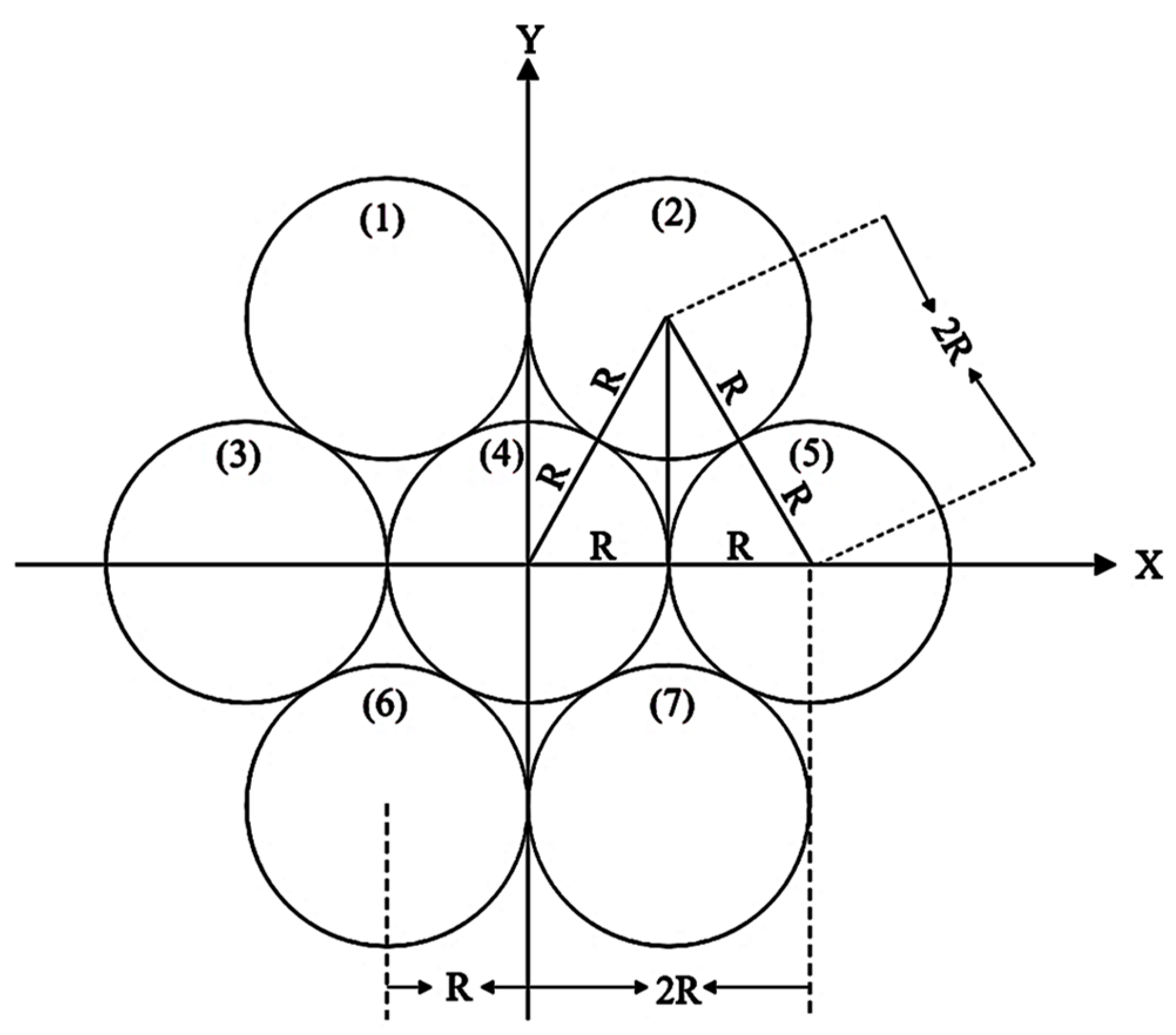
The destined TLs to be presented are to have their geometries constructed and materials set up. All TLs have the same construction manner starting from the face view arrangements of the circles (i.e., geometrical basis of each filament), then sinusoidal sweeping in the z-direction using a parametric curve. By taking into consideration the first stranded TL’s architecture (i.e., of seven filaments), the arrangement of each filament is based on the application of the Pythagoras law, as encapsulated in
Table 2 (since all filaments have the same radius ‘
R’).
The graphical arrangement of the x–y coordinates presented in
Table 2 is shown in
Figure 8 and represents the face view for the seven-filament stranded TL. The face view presented in
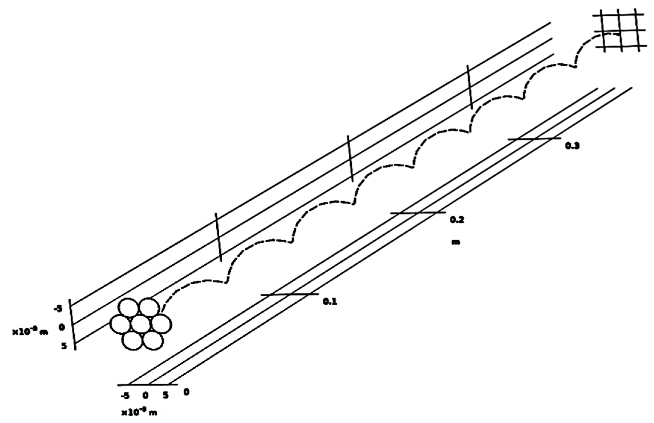
Figure 8 is to be swept along a sinusoidal function along its z-directed length. In other words, each circle of
Figure 8 is to be uniquely swept along a uniform sinusoidal function for all circles, as exposed in
Figure 9, where the total swept filaments would eventually constitute the stranded TL. This CAD procedure, uniformized for each TL, would ensure contacting filaments, in a realistic way, hence mimicking the appearance, as well as the physics, of real TLs.
When each circle of
Figure 8 is swept around the presented curve along the z-axis, the final form of the TL (in this case, the seven-filament) can be obtained. Concerning the materials for this particular TL (i.e., AL1 according to the norm EN 50182:2001(D)),
Table 3 represents its electrical and other characteristics. The electrical conductivity in
Table 3 for example represents the TL’s efficiency and performance in transmitting electrical power over long distances. The higher this value is, the lower the skin effect at high frequencies, for example, and the lower the power losses.
This factor, while not directly affecting the radiated MF, is to be taken into consideration (in addition to other TLs’ materials) when designing the sensor’s box of the DNeD’s project (in terms of constructing materials and possible interferences with the AL1). After building the face view, sweeping it along the parametric curve, and then assigning materials for the established geometry, the meshing process takes place. The FEA conducted by COMSOL and previously mentioned decomposes the space into smaller finite elements and then applies the mathematical reference model (
Section 3) onto each element. Therefore, the final output, which is the superposition of each element’s contribution, has its accuracy mainly affected by the mesh’s quality.
That is to say, the finer the mesh is, the better the obtained solution (i.e., precision of the obtained MF norm) and vice versa. Accordingly, the meshes chosen in this study were a trade-off between accuracy and heavy computational requirements. This described CAD execution process is identical for all TLs of 19 filaments, 37 filaments, 61 filaments, and 91 filaments; each of the mentioned TLs would have its design started as in
Figure 8, with the extra circles (i.e., filaments after sweeping) properly arranged onto the added rows of the entire geometry. The materials are selected according to the norm EN 50182:2001(D); then, at last, each TL’s geometry is “meshed” appropriately. By bearing in mind what has been precedent,
Figure 10 represents a major overview for some of the TL’s design.
7. Results, Discussion, and Future Work
It can be revealed through the numerical analysis of
Table 4, that the minimum resulting MF due to the injection of the total current of 10 A has a value of 8.134 × 10
−2 mT located at P2 (
Figure 12). On the contrary, the resulting MF with the biggest amplitude due to the injection of a total current of 110 A has a value of 1 mT (at P1). On average, the resulting MF for the seven-filament TL has a value of 5.74 × 10
−1 mT. For this particular TL, considering the two selected points of observation, as in
Figure 12, a TMR with a sensitivity ranging from 0 to 1 mT will be able to detect the current-resulting MF, induced with currents from 10 to 110 A. The graphical interpretation concerning the relationship among the injected current norms, the average radial distance, and the obtained magnetic fields around the 7-filament and 19-filament TLs is presented in
Figure 15.
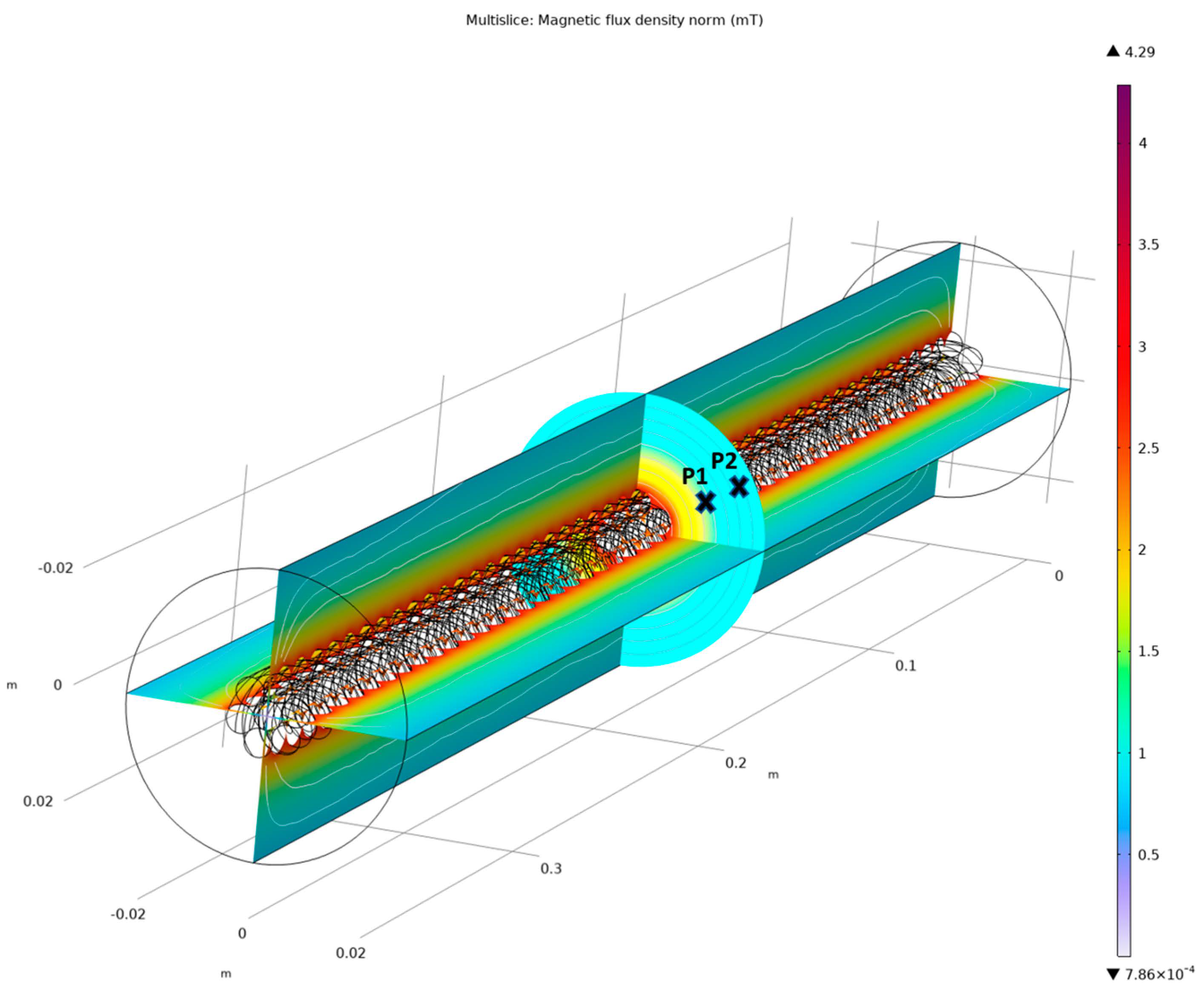
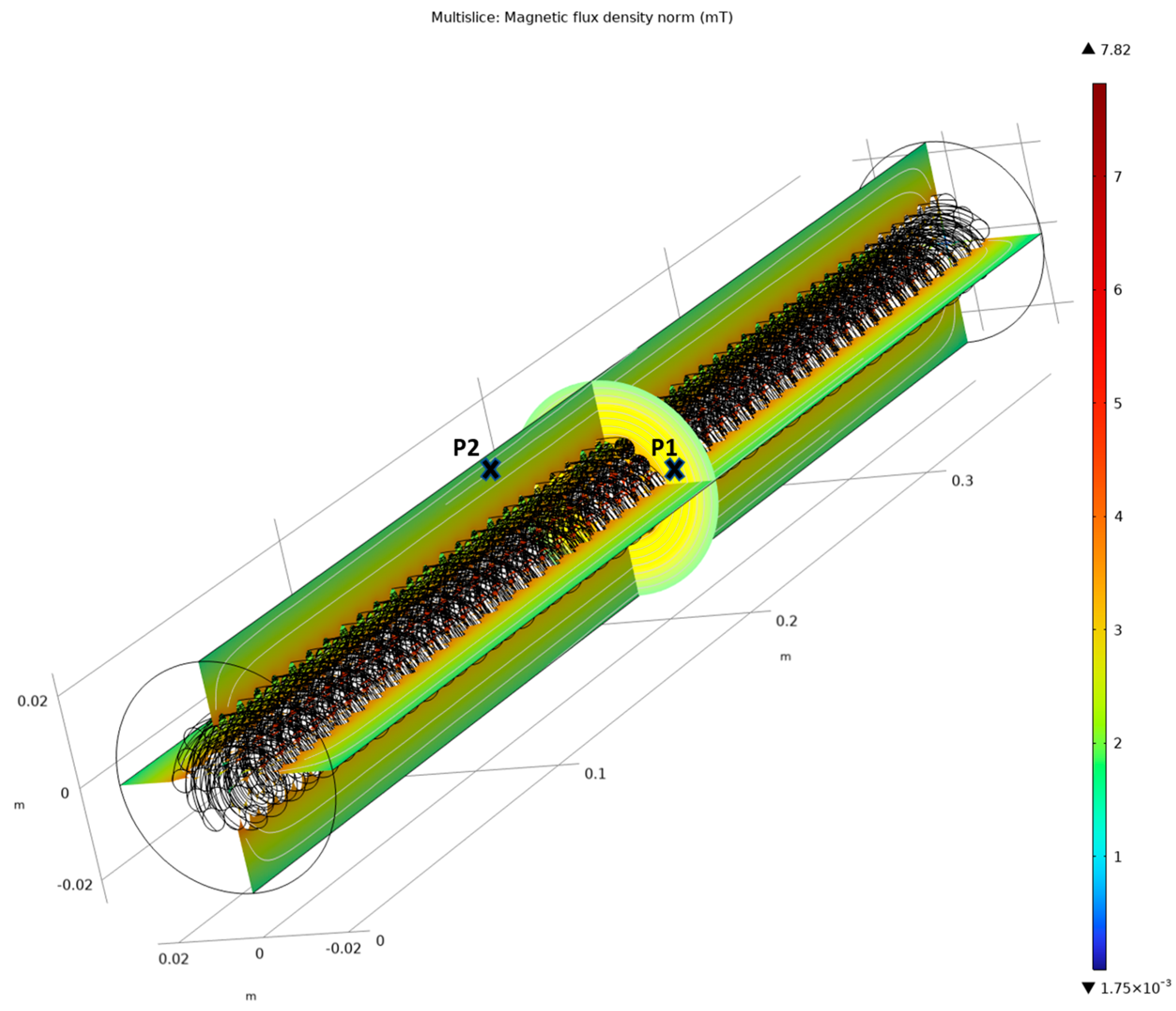
In light of the MF visual representation in
Figure 12, it is clear to say that there are not any specific points for referencing the TMR installation (for this TL, as well as all other TLs in this study) around the TL (as in this case: P1 and P2), rather than the observation points, which can be anywhere, underneath the virtual boundary. For the cases where the TMR sensors cannot be fitted under the virtual boundary with its actual radial wideness (for the seven-filament TL: 20 mm), this criterion can be easily expanded in the corresponding COMSOL model. For this reason, the coordinates of point P in the space underneath the virtual boundary in
Table 4 can have larger values with respect to the extended virtual boundary’s geometry. From another side, for the 19-filament TL and after the injection of the currents in
Table 5 (quantities justified), the maximum resultant MF is valued at 2 mT, which is double that of the MF as in the case of the 7-filament TL. The minimum MF is hence valued at 4.67 × 10
−1 mT, which is almost ten-fold bigger than the minimum MF for the seven-filament TL. Moreover, the average MF is valued at 1.117 mT, where accordingly, a TMR with a sensitivity from 0 to 2 mT would work fine in detecting the MFs under the virtual boundary of 60 mm of radius.
Any observation points other than P1 and P2 that are presented in
Figure 12, around the TL in space, can be selected for a proper TMR installation. Since it is not practical to involve each point in the space of the virtual boundary, the observation points of
Figure 12 were selected for demonstration purposes only. In regards with the increased number of filaments and the consequential proportional increase in the current-carrying ability, the 37-filament TL showed a minimum resulting MF of 8.20 × 10
−1 mT and a maximum of 3 mT. Such marginal values are due to the injection of the sample currents presented in
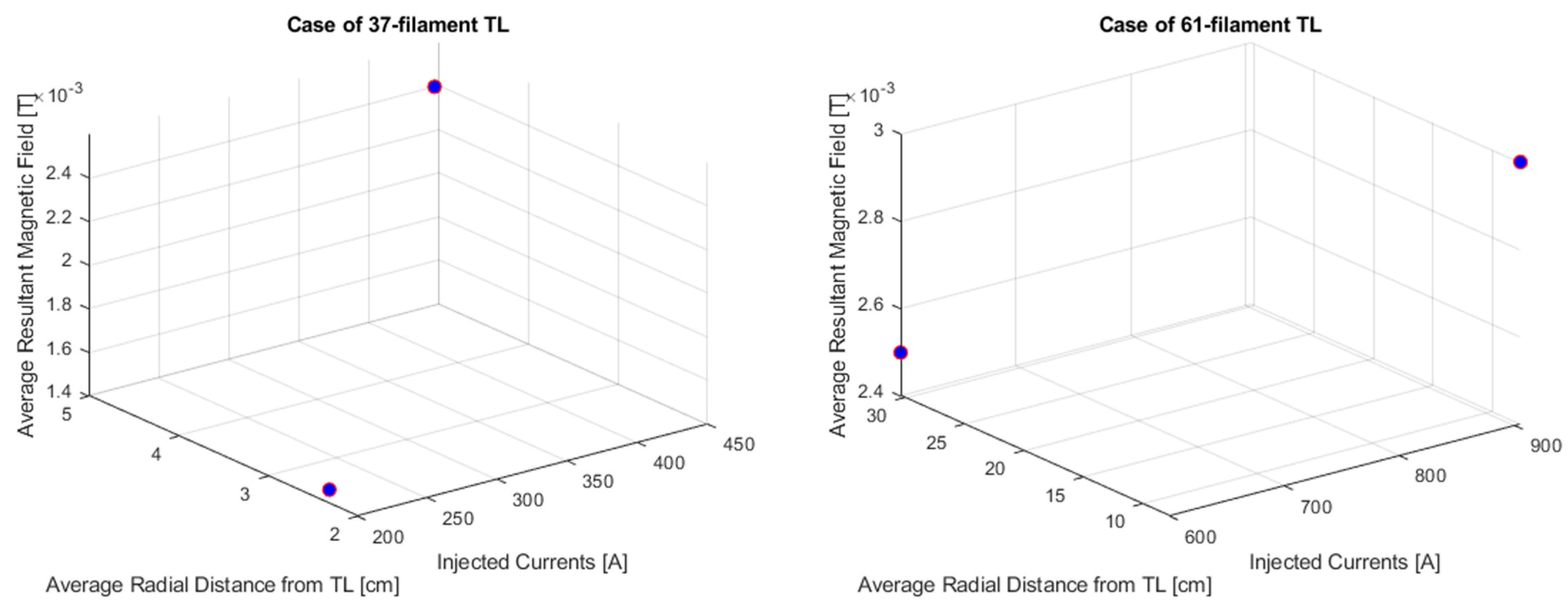
Table 5. Since this TL has a wider cross-sectional area as compared to its precedents (i.e., 7-filament, and 19-filament TLs), its virtual boundary’s radius is set to 100 mm, hence allowing for more space for the installation of the TMR around the TL. The graphical interpretation concerning the relationship between the injected current norms, the average radial distance, and the obtained magnetic fields around the 37-filament and 61-filament TLs are presented in
Figure 16. By comparing it to the seven-filament TL, its maximum MF is three times bigger. A TMR with a sensitivity rate from 0 to 3 mT would hence be able to detect the resulting MFs from the 37-filament TL, for all flowing currents from 0 to 425 A. As for the 61-filament TL and considering the values of the injected currents in
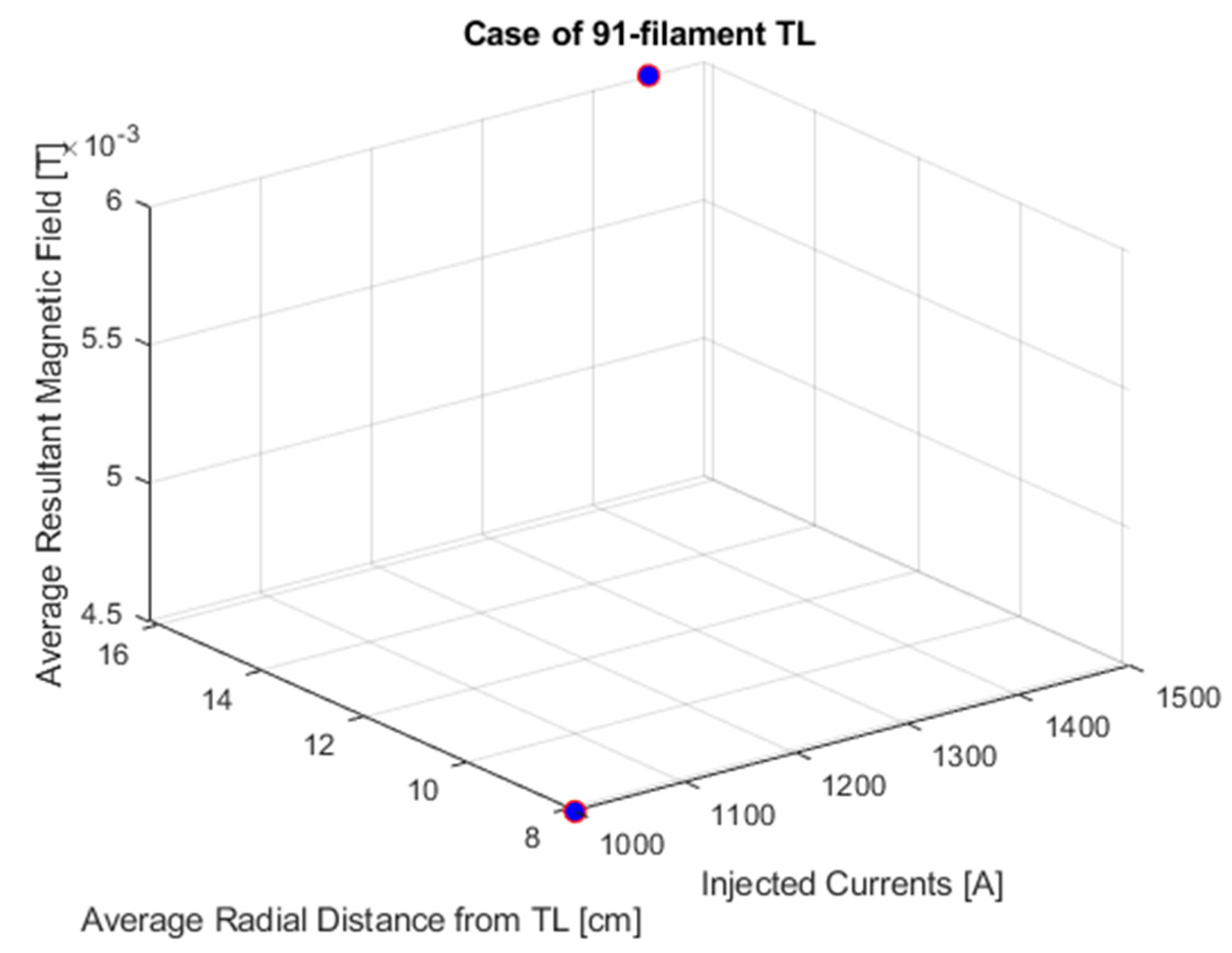
Table 8, a maximum MF is seen valued at 5 mT where the minimum MF scored 1 mT, which is the maximum MF for the 7-filament TL. Therefore, a TMR with a sensitivity range from 0 to 5 mT under the virtual boundary with a radius of 150 mm would be able to detect currents passing through this TL from 0 to 905 A. At the final stage, the 91-filament TL, which represents the largest simulated electrical stranded cable in this study, had an average MF of 5 mT where the maximum MF scored an 8 mT with respect to the injected currents in
Table 8, as well as the observation distances, under a virtual boundary with a 200 mm radius. Accordingly, a TMR installed anywhere around this TL with a radial distance less than or equal to 200 mm would be able to detect the MFs, which reflects the flowing currents from 0 to 1450 A. The graphical interpretation concerning the relationship among the injected current norms, the average radial distance, and the obtained magnetic fields around the 91-filament TL is presented in
Figure 17. Regarding other analogous studies, the approach conducted in this manuscript represented a thoroughly detailed methodology, thus enabling the straightforward selection of TMR sensors based on the values of the inducing currents. For instance, the obtained numerical data of the resulting MFs, without the need for excessive mathematical computations in order to know the range of TMR sensitivity. The study in reference [
25], on the first hand, despite its relative accuracy in evaluating the MFs, still has its FEA based on meshes with triangular elements, unlike the tetrahedral elements used in this study, which have more accurate representations of complex 3D geometries (i.e., stranded transmission lines). From another side, the work in reference [
26] took into consideration only two static models for overhead TLs (i.e., 161 kV and 330 kV), such that MFs are then calculated by using GetDP 3.4.0 software. This procedure hence reflects a lack of flexibility, when considering other types of overhead TLs, unlike the strategy proposed in this work. Here, after simple modifications in the resultant COMSOL models (e.g., TL’s architecture, number of strands, current norm, etc.), the MF can be dynamically obtained. On the other hand, the work in [
27] did consider the impact of conductor sag on the generated MF near power facilities, which still has only accounted for a single-circuit 400 kV TL. On the other hand, the reliable methodology presented in this paper takes into consideration different stranded TLs, subjected to different currents, with a feasibility to be extended into further TL geometries. The other COMSOL-based FEA for calculating the MFs around TLs, such as the study in [
28], deliberates on the MF effects on human bodies, unlike the present study, which aims to accurately select the TMR to be employed in UAS-based TL remote monitoring.
It is noteworthy to mention that this FEA-based approach requires more calculation time and computational resources due to the complex meshing techniques needed when taking into consideration the proximity effect for example [
29]. Other new studies exist for calculating the magnetic vector potential in multilayered electrical wires, under externally influencing harmonic MFs. With that being said, such a developed algorithm considers skin and proximity effects when calculating MFs for multilayered wires with less computational times [
30]. Concerning each of the simulated TL magnetic norms in this study, all data and results were presented in the form of samples. This is to reassure that the coordinates in
Table 4,
Table 5,
Table 6,
Table 7 and
Table 8 do not restrict the applicability of this study when considering other coordinates/distances from each TL. This fact also applies to virtual boundary geometry, where the obtained COMSOL models can have the virtual boundary geometries (i.e., radius) easily adjusted. Hence, the generalized models can be flexibly adjusted for any other measurements/electrical modifications, thus allowing for a general MF visualization around TLs at any distance, with respect to any injected current.
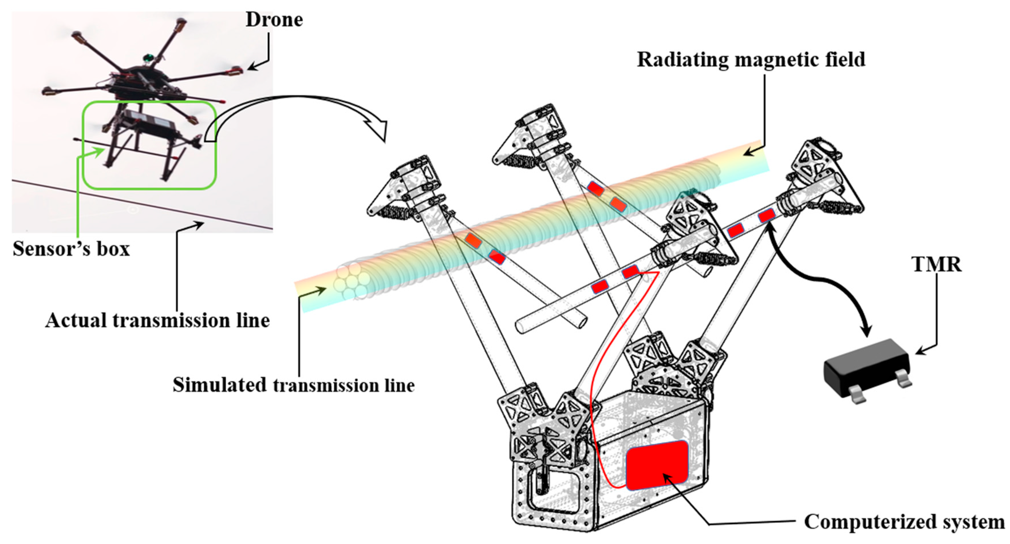
According to the preceding analysis, this paper suggests the future implementation of the resulting numerical MF data (i.e., to be acquainted with the physical TMR), through a computerized system to be installed in the DNeD’s project sensor box: this box is to be released from the drone onto a TL, where specifically, this study can be incorporated in the box itself, as exposed in
Figure 18. The TMR sensors, having their positions fixed on the mechanical holding tubes of the box, as shown in
Figure 18, would have their output voltages (i.e., reflecting images of the sensed MFs) transmitted via electric wires to the computerized system represented by a red box in
Figure 18. The TMR sensors are encouraged to be fixed on the four fasteners, in order to have the most accurate picture of the resulting MF; in this way, the final output voltage would be better calibrated by taking into consideration the signals sensed at each corner of the box. Through analog input channels, the computerized system, which can be any type of microcontrollers (e.g., RaspBerry Pi), can hence reflect the flowing current’s amplitude by means of an analog-to-digital signal conversion, regarding its bandwidth. Therefore, the current flowing through a TL can be non-invasively sensed, by means of a UAS, drone-controlled operation. Additionally, a remote communication module can be also installed in the box of
Figure 18, in a way that the acquainted electrical current’s information can be transmitted to a local station, for further analysis. For example, a wireless communication module can transmit the data (e.g., numerical currents’ magnitudes, time-sampled) to a nearby station underneath the TL, for a proper visualization and investigation about the grid’s overall health.
The suggested design is straightforward and simple for real execution in a way that the distances between the TMR sensors (i.e., red rectangles on each fastener) can be easily adjusted when considering space coordinates, other than the ones presented in
Table 4,
Table 5,
Table 6,
Table 7 and
Table 8. In other terms, the designed COMSOL models in this study are firstly scalable and adjustable for any TL architecture, including the geometries of the virtual boundaries. With that being said, the ranges of MFs can be easily acknowledged with respect to other TL configurations, as well as other ranges for the flowing currents. This scalability can be easily, in turn, reflected by the box in
Figure 18, by only changing the distances from/between the TMR sensors and the TL, on each fastener. The scaling on the level of the computerized system must be also adjusted to accommodate the increased/decreased values of MFs and electrical currents. Moreover, since the drone would be temporarily holding/releasing the sensor’s box, there would not be any need to take into consideration vibrational studies: generally, drone-based applications must undergo specific vibration tests, especially for the power electronic components, due to the effects of the continuous rotational movements of the drone’s shafts. In this case, the drone would only be acting as a conveyance medium, only “delivering” the box of
Figure 18 with its added equipment, over the TL. Through this temporary interaction between the drone and its embedded box, no vibration studies are hence required for the suggested circuits of
Figure 18.
