Article

Effects of Mechanical Stress on the Life and Insulation Performance of DC-Link Capacitors

1
Wuxi Power Filter Co., Ltd., Wuxi 214112, China
2
Department of Electrical Engineering, Tsinghua University, Beijing 100084, China
*
Author to whom correspondence should be addressed.
Energies 2024, 17(3), 699; https://doi.org/10.3390/en17030699
Submission received: 6 December 2023 / Revised: 5 January 2024 / Accepted: 22 January 2024 / Published: 1 February 2024
(This article belongs to the Section F: Electrical Engineering)

Abstract

:
Mechanical stress is a crucial factor affecting the life and insulation performance of DC-link capacitors (DCLCs). However, at present, there is a lack of long-term experimental observations on the effects of mechanical stress on the life and insulation performance of DCLCs. The element-winding process for DCLCs is carried out by winding metalized film on a reel and adjusting the various winding tensions and pressures according to performance requirements, usually with a winding tension coefficient (WTC) of kT = 1.5. The pull pressure of the winding machine on the film produces tension during the elements’ winding process, and the tension in the film grows after the heat-setting process. In this study, by adjusting the four tension coefficients of the elements in the winding process, which were 1.4, 1.5, 1.6, and 1.7, various winding tensions of the DCLC components were changed. Additionally, various heat-setting shrinkage tensions were appropriately generated by setting different heat-setting temperatures (HSTs). Relevant test platforms were established, and a life aging test, insulation resistance measurement, and withstand voltage test were performed on these DCLCs at different tension coefficients and HSTs. The obtained results reveal that the mechanical stress of DCLCs is affected by the parameters of the material itself, including the tension coefficient during the winding process and the HST. The winding tension affects the life of DCLCs, such that those with the highest tension (kT = 1.7) demonstrate the longest life at an HST of 105 °C, whereas samples with the lowest tension (kT = 1.4) exhibit the longest life at an HST of 110 °C. HSTs are capable of improving the lifetime of DCLCs. HSTs are also able to improve the withstand voltage capability of DCLCs, but the tension is not proportional to the withstand voltage capability of DCLCs. This research provides a suitable basis for further explorations of the life and insulation performance of DCLCs.

1. Introduction

A metalized polypropylene film capacitor (MPFC) is made of biaxially oriented polypropylene (BOPP) films with a metal layer via vacuum evaporation. MPFCs have the advantages of high-temperature tolerance, high voltage, large ripple current, and long service life [1,2,3,4]. A DC-link capacitor (DCLC) is a kind of MPFC with a self-healing function. As one of the main converter devices, DCLCs play vital roles in voltage equalization, energy storage, and filtering, and are extensively utilized in smart grids, new energy, rail transit, and other fields [5].
As key devices of converters in flexible DC transmission projects, DCLCs have been extensively utilized [6]. The number of DCLCs amounts to tens of thousands in each flexible DC transmission project, and their service life typically reaches 40 years [7]. Therefore, the life of DCLCs is commonly regarded as a very crucial performance indicator.
DCLCs are subject to a DC field strength of more than 200 V/μm [8]. In engineering technology, dielectric constant, dielectric loss, insulation resistance, and breakdown characteristics are the main insulation performance parameters of dielectrics. The dielectric constant of DCLCs is essentially unchanged during usage; therefore, their insulation performance is chiefly influenced by dielectric loss, insulation resistance, and breakdown properties.
Up till now, relatively few investigations have been devoted to the effect of mechanical stress on the life and insulation performance of DCLCs. Studies on MPFC lifetime and its influencing factors mainly focus on failure mechanisms, reliability evaluations, and MPFC lifetime predictions under temperature, voltage, and humidity conditions [9,10,11,12,13]. The explorations of mechanical stress performed in MPFCs were mainly concentrated on internal pressure distribution [14], the calculation of internal pressure [15], and breakdown characteristics [16,17]. According to the literature [18], the research results revealed that interlayer pressure has a negative effect on the breakdown characteristics of the studied materials. Additionally, the calculated dielectric breakdown strength of metalized BOPP films indicated a reduction of 257 V/μm when the interlayer pressure was raised to 1.0 MPa. The obtained results in Ref. [19] indicated that interlayer pressure in the range of 50–800 kPa has a positive correlation with surface flashover voltage and field strength. In Ref. [20], the results revealed that interlayer pressure in the range of 20–800 kPa is negatively correlated with the action integral to the self-healing current at higher breakdown points in AC voltage. In the literature [21], the results indicated that the rate of change in a capacitor is in the range of 1–2%, and the rate of change in dielectric loss is in the range of −0.1–0.1% when mechanical pressure is applied within a range of 7650–7950 g. These investigations revealed that the main factors affecting MPFC life include working voltage, working temperature, and humidity, and these investigations have also shown that mechanical stress on the self-healing current, breakdown field strength, capacitance, and dielectric loss are characteristics of MPFCs. However, the objectives of the above explorations and mechanical stress conditions have specific limitations, such as the testing of polypropylene films, capacitors in the pulse field, internal pressures in the range of 20–800 kPa, and winding mechanical pressures in the range of 7650–7950 g. Although these studies serve as appropriate references for analyzing the effect of mechanical stress on the life and insulation performance of capacitors, there is a great need to further examine the effects of mechanical stress on the life and insulation performance of DCLCs.
The main purpose of this study is to explore the effect of mechanical stresses on the life and insulation performance of DCLCs via tension during element winding and the shrinkage tension during the heat setting of DCLCs as studied mechanical stresses. To this end, DCLC mechanical stress and heat settings were rationally examined. Tangential loss angle measurement, insulation resistance measurement, withstand voltage test, and life aging test were carried out. The obtained results reveal that winding tension and heat-setting shrinkage tension influenced the lifetime and insulation performance of DCLCs. The achieved results can be employed to analyze and solve problems related to mechanical stress, insulation performance, and lifetime of DCLCs in the field of metalized polypropylene film capacitors.

2. Mechanical Stress of a DCLC

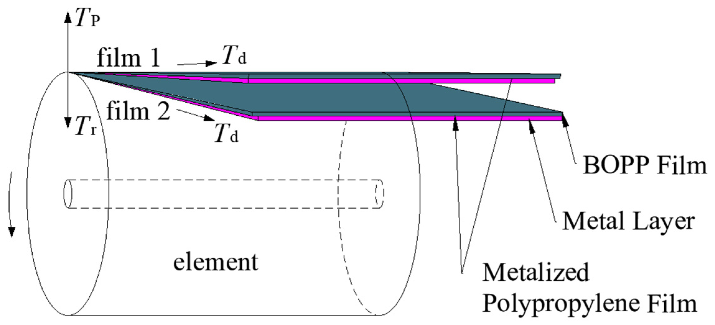
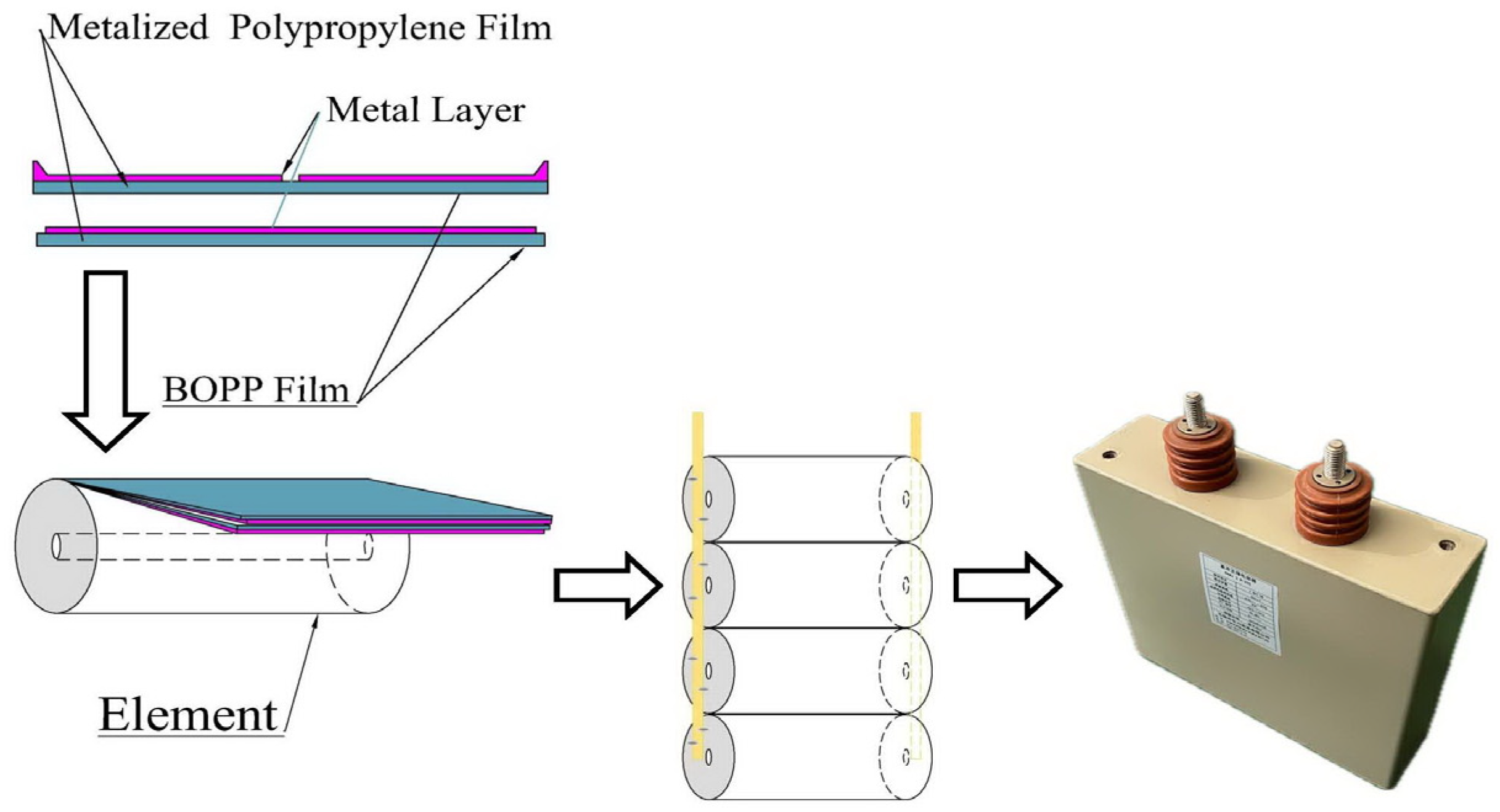
2.1. Elements of a DCLC

A DCLC consists of a shell, terminals, elements, a connecting copper bar, insulating parts, and a filled insulating dielectric.
This element is formed by winding two layers of metalized polypropylene films on a mandrel and then spraying some metallic materials on both ends as two electrodes. In general, two element shapes—namely, cylindrical and flat—are of interest to technologists and scientists. Herein, the cylindrical element was examined, as illustrated in Figure 1.

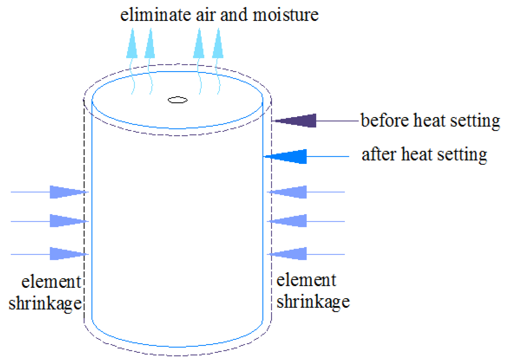
2.2. Heat Setting of the DCLC

Heat setting is an important process of the treatment of elements, as it is commonly employed to form them. The heat-setting process mainly comprises the following steps: placement of elements, heat setting, cooling, inspection, and removal of elements. In the element-winding process, the metalized film cannot be completely tight, and there are always gaps between film layers. Moisture and air in the gaps reduce the breakdown field strength of the elements. Additionally, partial discharge of these gaps will be easy and will lead to the shortening of the service life of the element. The heat-setting process can significantly reduce these adverse effects.
The effect of heat setting is presented in Figure 2. During the heat-setting process, the films undergo irreversible heat shrinkage that leads to the tension growing of the element films, tightening the layers, and squeezing out the air and moisture in the gaps.

2.3. Mechanical Stress of the DCLC

Figure 3 represents a schematic diagram of the winding process of DCLC elements. When the DCLC element is wound, the pull pressure of the winding machine on the film forms a tension force (Td) on the film. A contraction stress will be generated within the stretched film, creating a radial stress (Tr) on the capacitor element. It is assumed that the tension (Td) is uniformly distributed in the width direction of the film and its direction is always perpendicular to the axial direction of the film roll. The axial deformation of the film during winding of the element is very small. To facilitate the analysis, the pressure parallel to the axis is neglected and only the tension (Td) by the winding machine is taken into account. Considering each layer of the film as the object of study, it can be seen that the pressure on the film is balanced under the joint action of tension (Td), radial pressure (Tr), and reaction pressure (TP) generated by the film pressing on the element. After the heat-setting process, the tension within the film rises.
Longitudinal stress (σ) is generated on the film by the pull pressure during the winding process and heat setting [22]. According to the knowledge of the mechanics of materials, the relationship between the longitudinal stress (σ) and the tension (Td) on the film, as well as the cross-sectional area (S) along the stress direction, can be stated by
σ = T d b d 0 + η E S
where b is the film width, d0 is the film thickness, ES is the elastic modulus, η is the strain caused by film shrinkage, and its value varies in terms of the heat-setting temperature (HST).
The fundamental relation of the tensile pressure (T) on the film after heat setting is given as follows:
T = σ b d 0 = T d + η E S b d 0
The equation of tension (Td) on the film during winding is provided by
T d = k T b d 0
where kT represents the WTC.
The pressure coefficient (kF) is also set in the winding parameter settings, and the corresponding equation of the winding pressure (TF) on the film during winding is simply given by
T F = k F b d 0
where kF denotes the winding pressure coefficient (usually, its value is set as 12).
It can be seen from Equations (1)–(4) that the mechanical stress within the DCLC is affected by various factors, including the material itself, tension coefficient during the winding process, and HST.

3. Experimental Method

3.1. DCLC Sample Preparation

The DCLC sample selected for this experiment consists of four elements connected in parallel, and its capacitance is 200 ± 5% μF, as illustrated in Figure 4. Each element is wound with two layers of metalized film. The thickness of the film is considered as 6 μm, the width of the film is 150 mm, and the average resistance value of the square area of the metal coating is 35 Ω/□. The diameter of the element is 76 mm, and the corresponding inside capacitor consists of two series of segment structures. The rated voltage (UNDC) of the DCLC sample is set as 2800 V DC, and the rated working electric field strength (E0) is 233.3 V/μm.
The tension coefficients (kT) in the winding process are set as 1.4, 1.5, 1.6, and 1.7, respectively, and the corresponding tension (Td) magnitudes are 1260, 1350, 1440, and 1530 gf, respectively. In addition, the winding pressure (TF) on the film during winding is set as 10,800 gf. The elements of the DCLC samples are heated at two temperature levels: T1 = 105 °C and T2 = 110 °C.
Under the premise that the HST of the DCLC is 105 °C and the values of WTC (kT), in order, are set equal to 1.4, 1.5, 1.6, and 1.7, respectively, and the corresponding tension magnitudes (Td) are 1260, 1350, 1440, and 1530 gf, respectively, and the winding pressure (TF) on the film during winding is set as 10,800 gf. The samples used for the aging tests are itemized as C1.1, C1.2, C1.3, and C1.4, respectively, and the samples for the insulation resistance measurements are itemized as C1.11, C1.12, C1.13, and C1.14, respectively, whereas the samples used for the voltage withstanding tests are itemized as C1.21, C1.22, C1.23, and C1.24, respectively.
Under the premise that the HST of the DCLC is 110 °C and the WTC (kT) are 1.4, 1.5, 1.6, and 1.7, respectively, and the corresponding tension (Td) values are 1260, 1350, 1440, and 1530 gf, respectively, and the winding pressure (TF) on the film during winding is set equal to 10,800 gf. The sample used for aging tests are itemized as C2.1, C2.2, C2.3, and C2.4, respectively, and the sample employed for insulation resistance measurements are itemized as C2.11, C2.12, C2.13, and C2.14, whereas the sample used for voltage withstanding tests are itemized as C2.21, C2.22, C2.23, and C2.24, respectively.
The number of samples tested associated with each number (C1.1, C1.2, …, C2.24) was four. Therefore, in total, ninety-six test samples were implemented for the above three tests.

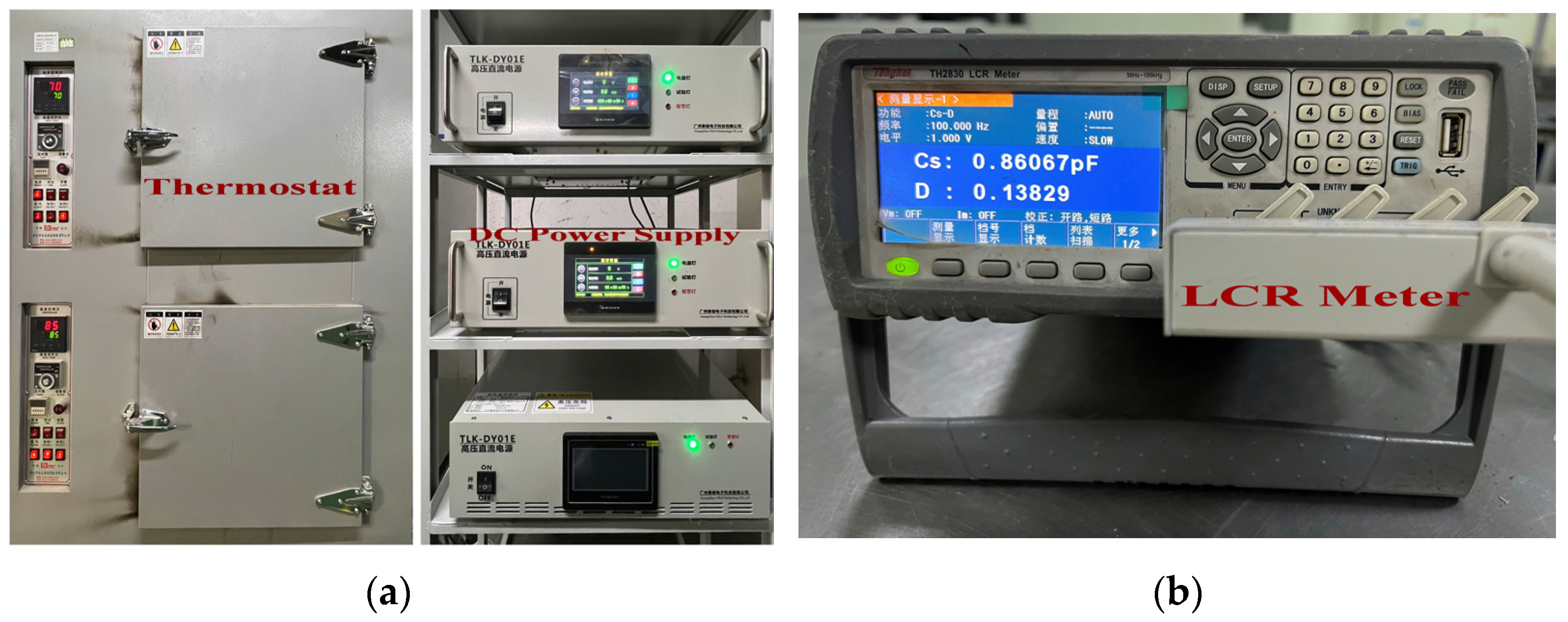
3.2. Life Aging Test

A test platform was set up, consisting of the necessary equipment and measuring devices for the life aging test, as presented in Figure 5. The thermostat is capable of controlling the temperature from 20 °C to 150 °C. The DC power supply is able to supply 0–8000 V DC. In addition, an LCR meter was utilized to measure the capacitance and tangent of the loss angle (usually, the testing frequency is set as 100 Hz).
The test method refers to the durability test of IEC 61071: 2017 Capacitors for Power Electronics [23].
The test method procedures are as follows: First, the capacitance and tangent of the samples are measured at room temperature. Then, the samples are placed in the test thermostat until the temperature of the samples reaches 70 °C. Next, the voltage of 1.4 UNDC is applied to the samples. After 100 h, the samples are taken out and their capacitance and tangent of the loss angle are immediately measured. Then, they are placed into the test thermostat and 1.4 UNDC voltage is applied to them at 70 °C. After 150 h, the samples are taken out and the capacitance and tangent of loss angle values are immediately measured. Then, they are placed into the test thermostat and, again, 1.4 UNDC voltage is applied at 70 °C for a longer time duration. After the end, the samples are taken out, and the capacitance and tangent of the loss angle are immediately measured. After cooling the samples, the capacitance and the tangent of the loss angle are measured again. Before and after the test, the rate of change of the capacitance should not exceed 3% [23]. The time value of the test with a capacitance change rate of −3% characterizes the life of the capacitor.
The capacitance (Ct) measured at high temperatures can be converted to the capacitance (CT) at room temperature according to the following equation:
C T = C t + k c ( T t T 0 ) C t
where Tt represents the high-temperature value, T0 denotes the room-temperature value, and kc is the temperature coefficient of the BOPP film capacitance (commonly set as −0.0002/K).
The capacitance change rate ∆C (%) can be calculated based on the following equation:
Δ C ( % ) = C 1 C 0 C 0 × 100 %
where C1 denotes the capacitance after the test, and C0 represents the capacitance before the test.

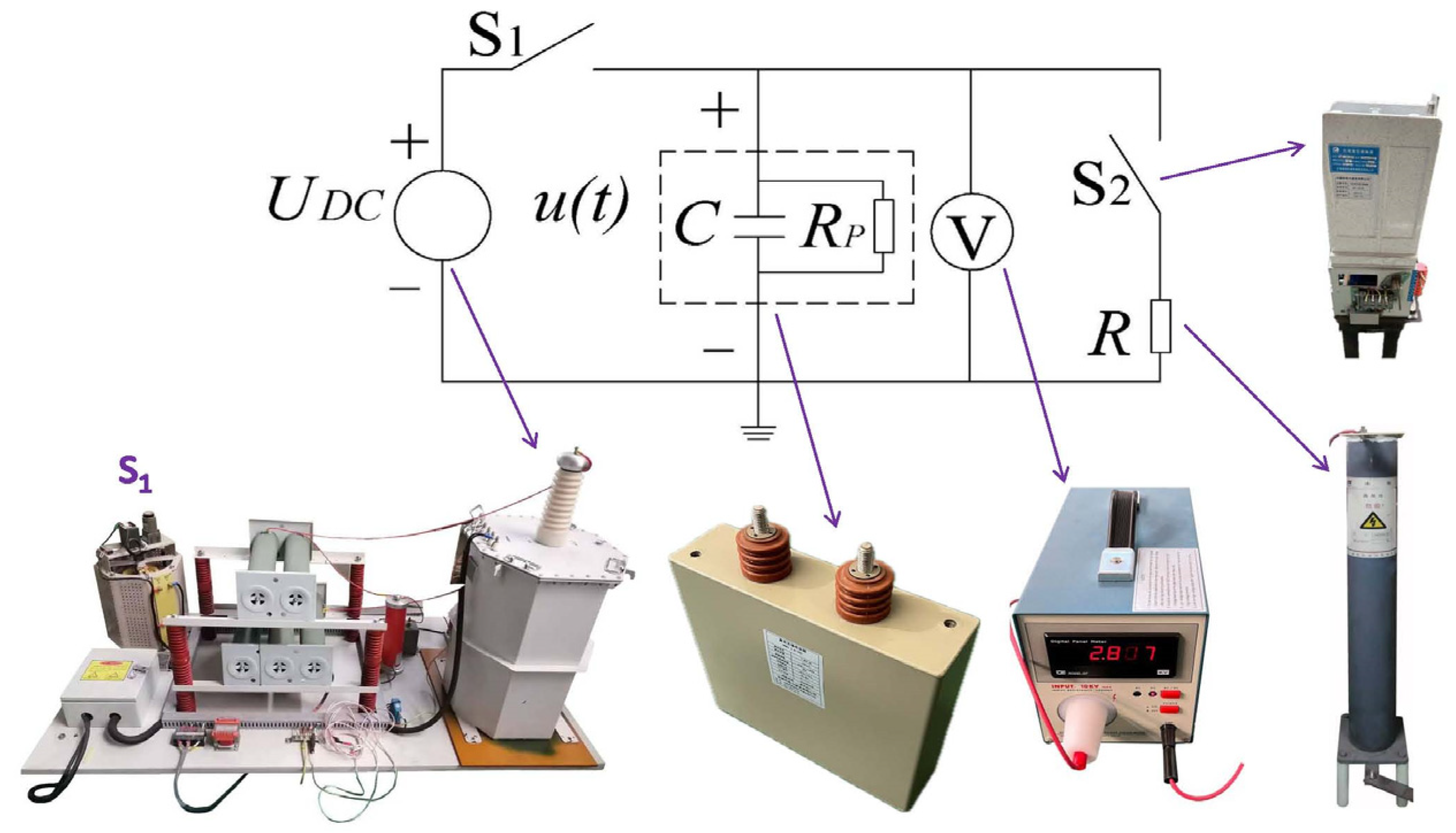
3.3. Insulation Resistance Measurement

A test platform consisting of the necessary equipment and a measuring device was set up to measure the insulation resistance. The measurement circuit of the test platform is presented in Figure 6. In the figure, C is the equivalent capacitance of the sample, RP is the insulation resistance of the sample, UDC is the DC power supply, S1 is the charging switch, S2 is the discharge switch, R is the discharge resistor, and V represents the high-impedance digital voltmeter (the measurement range of DC voltage is 0–10,000 V, and the input impedance is 1000 MΩ).
The sample is placed in the test thermostat to maintain the test temperature. To eliminate the effect of the sample surface leakage current on RP, a ground wire is employed to bypass the surface leakage current. The surface conductance of a clean dry solid dielectric of the sample is very small; that is, the value of the surface insulation resistance is very high. Therefore, this test does not consider the measurement of surface insulation resistance, and the surface conductance is assumed to be zero.
The test procedure is as follows: Set the thermostat temperature to 20 °C and place the sample in the thermostat for at least 12 h. Connect the test circuit as shown in Figure 6. First switch S2 off, then switch S1 on, and charge the sample with a test voltage of U0 for 1 min. Then switch S1 off, and let the sample self-discharge. After a period of time t, use the V to measure the voltage to obtain Ut and the LCR meter to measure the capacitance value. Finally, the insulation resistance (RP) of the sample is calculated by employing Equation (7). After the test is completed, S2 is closed, and the sample is discharged through the resistance R:
R P = t C ln U t U 0
where U0 represents the initial voltage at the beginning of self-discharge, Ut denotes the voltage at self-discharge to time t, t is the time of self-discharge, and C is the capacitance of the sample.
The setting sequence of the initial voltage U0 is as follows: 1.0 UNDC for the first time. Then it gradually increases, with the voltage increasing by 0.1 UNDC each time, until U0 reaches 2.0 UNDC.

3.4. Withstand Voltage Test

A test platform was set up, consisting of necessary equipment and measuring devices for the withstand voltage test. The test circuit of the test platform is also illustrated in Figure 6.
The test method refers to the voltage test between terminals of IEC 61071: 2017 Capacitors for Power Electronics.
The test method is as follows: First, set the test temperature at 20 °C in the thermostat. Then, place the sample into the thermostat, keep it for 12 h or more, charge the sample to a test voltage value of 5 min, and then use the LCR meter to measure its capacitance value and calculate the capacitance change rate. Setting of test sequence: the initial test voltage is 1.5 UNDC, and then the test voltage is gradually increased by 0.1 UNDC each time until the sample fails.
The capacitance change rate ∆C (%) can be calculated according to Equation (5).

4. Experimental Results and Discussion

4.1. Life Aging Test

Life aging tests were performed on DCLC samples with two HSTs and four levels of the winding tension coefficient, during which the capacitance value was measured several times and the average value of the samples was used to obtain the relationship curves of capacitance change rate and tangent of the loss angle as a function of time. The test results of four kinds of samples with different WTCs at an HST of 105 °C are illustrated in Figure 7 and Table 1. The test results of four types of samples with different WTCs at an HST of 110 °C are presented in Figure 8 and Table 2.
According to Figure 7 and Table 1, in the case of HST = 105 °C, the capacitance change rates of the samples after 100/500/800 h of testing were reported to be 0.022/−1.458/−3.44%, −0.011/−1.692/−7.245%, 0.044/−0.608/−2.239%, and 0.056/−0.502/1.985% for the WTCs of 1.4, 1.5, 1.6, and 1.7, respectively. In the meantime, the samples with WTC = 1.7 (corresponding to the tension of 1530 gf) exhibited the lowest capacitance change rate in the entire test. Further, the rate of change of the capacitance of the samples with WTC = 1.5 (corresponding to the tension of 1350 gf) after 500 h of testing demonstrated a growth of 3%.
According to presented results in Figure 7 and Table 1 for the case of HST = 105 °C, the capacitance change rate of the samples first increases and then decreases as the experiment continues. This is essentially ascribed to the fact that during heat setting, the element’s metalized polypropylene film shrinks, and during the aging test, the element’s metalized polypropylene film shrinks due to electromotive pressure and electrical stress, and as a result, the capacitance increases. However, during the test, due to the self-healing of the weak point of the metalized polypropylene film after the failure, the electrode area is reduced, so the capacity of the element also reduces after the test.
According to the plotted results in Figure 7 for the case of HST = 105 °C, the tangent of the loss angle of the sample grows with four winding tension factors after 800 h of testing. Meanwhile, the tangent of the loss angle of the samples with WTC = 1.7 after 500 h of testing exhibits the lowest value.
Based on the results provided in Figure 8 and Table 2 for the case of HST = 110 °C, the capacitance change rates of the samples after 100/500/800 h of testing were reported to be 0.040/−0.281/−0.915%, −0.006/−0.414/−1.391%, 0.071/−0.290/−2.12%, and 0.052/−0.209/−1.693% for the WTCs of 1.4, 1.5, 1.6, and 1.7, respectively. Among them, the rate of change of capacitance of the samples with WTC = 1.7 in the first 500 h of testing is the lowest, samples with WTC = 1.4 (corresponding to the tension of 1260 gf) after 800 h of the test exhibit the smallest rate of change of capacitance, and the rate of change of capacitance of the sample with WTC = 1.6 (corresponding to a tension of 1440 gf) presents the largest after 800 h of testing but does not exceed −3%.
According to Figure 8, in the case of HST = 110 °C, the capacitance change rate of the samples also increases and then decreases as the test continues, and the tangent of the loss angle of the sample with the three levels of the WTC after 800 h of the test remains unchanged except that the tangent of the loss angle of the sample is increased by a WTC of 1.5. The tangent of the loss angle of the specimen with WTC = 1.5 is increased by 1 × 10⁻¹; however, this value is within the acceptable range for engineering applications. Generally, the loss of DCLC consists of three parts: dielectric loss, leakage loss, and contact loss. The dielectric loss is related to the dielectric material and working temperature. Leakage loss is related to the leakage resistance of the metalized film. Finally, the amount of contact loss relies on the square resistance structure, vaporization process, and production technology level. In the life aging test, when the sample occurs after the self-healing samples, the local insulation of the metallization film increases, thus leading to the growth of the loss. The dielectric material is also a factor influencing the increase in losses.
As can also be seen from Figure 7 and Figure 8:
(1)
The HST is capable of improving the service life of the understudy DCLCs, the temperature increases by 5 °C, and the capacitance changes of all four winding tensions exhibited an increase of 73.8%, 80.8%, 5.3%, and 7% after 800 h of the aging test. This issue is essentially attributed to the fact that during hot polymerization, the polypropylene homopolymer chain is reoriented through high temperatures. Additionally, secondary crystallization occurs after the crystalline molecular chain acquires a certain energy, which alters the crystallinity and the crystalline shape of the film, and the crystallinity linearly enhances with the temperature growth [24]. As the crystallinity increases, it would be difficult for ions to move in the polypropylene film, the conductivity decreases, and the insulation resistance becomes 3–5 times larger [25], which noticeably improves the ability to store charge and maintain voltage [26]. The plotted results indicate that the appropriate increase in HST is capable of growing the crystallinity of the medium, enhancing the insulation performance, and prolonging the service life of the capacitor.
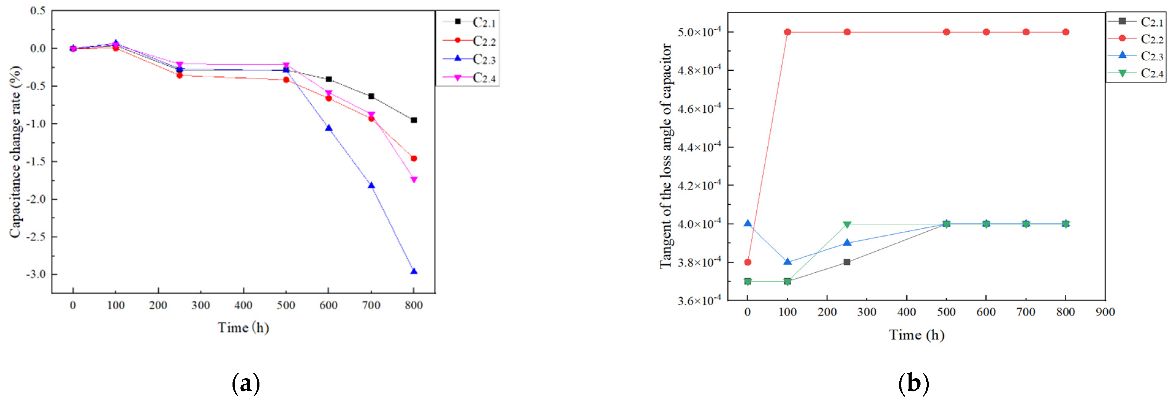
(2)
With the increase in the HST from 105 °C to 110 °C, the tangent of the loss angle of the DCLC for four WTCs exhibits a descending trend after 800 h of testing.
At present, the same aging test of DCLC with metalized BOPP film with 6 μm thickness has been investigated. The lifetime of the sample element aged at 1.4 UN was reported to be 768 h at a temperature of 60 °C (the limit of capacitance change rate should not exceed 3%) [6]. Just from the test data in the present investigation, only the test results of the tension coefficient of 1.5 are worse than the comparative test results at HST = 105 °C. Additionally, the test results of the tension coefficient of 1.4 in this study are slightly close to the comparative test results at HST = 105 °C, and other test results are obviously better than these comparative test results. However, the test temperature of the comparative test is 10 °C lower than the test temperature of this study. Since the temperature is a crucial factor that affects the life of the MPFC, a 10 °C rise in temperature will cause a much shorter life. If the temperature of the comparative test is increased by 10 °C, the test results may not be better than the present test results, indicating that such results can be still regarded as a rigorously suitable reference work.

4.2. Measurement of the Insulation Resistance

The self-discharge test values of the samples are measured in the presence of various initial discharge voltages, and then the insulation resistance values are calculated. The DCLC insulation resistance is found to be dispersed, requiring multiple sets of measurements to be averaged. The relationship between the insulation resistance values of the samples with various WTCs and the initial discharge voltage values is presented in Figure 9 and Table 3 and Table 4. The HSTs of the samples whose obtained results are provided in Figure 9a,b are 105 °C and 110 °C, respectively.
As can be seen from Figure 9 and Table 3 and Table 4:
(1)
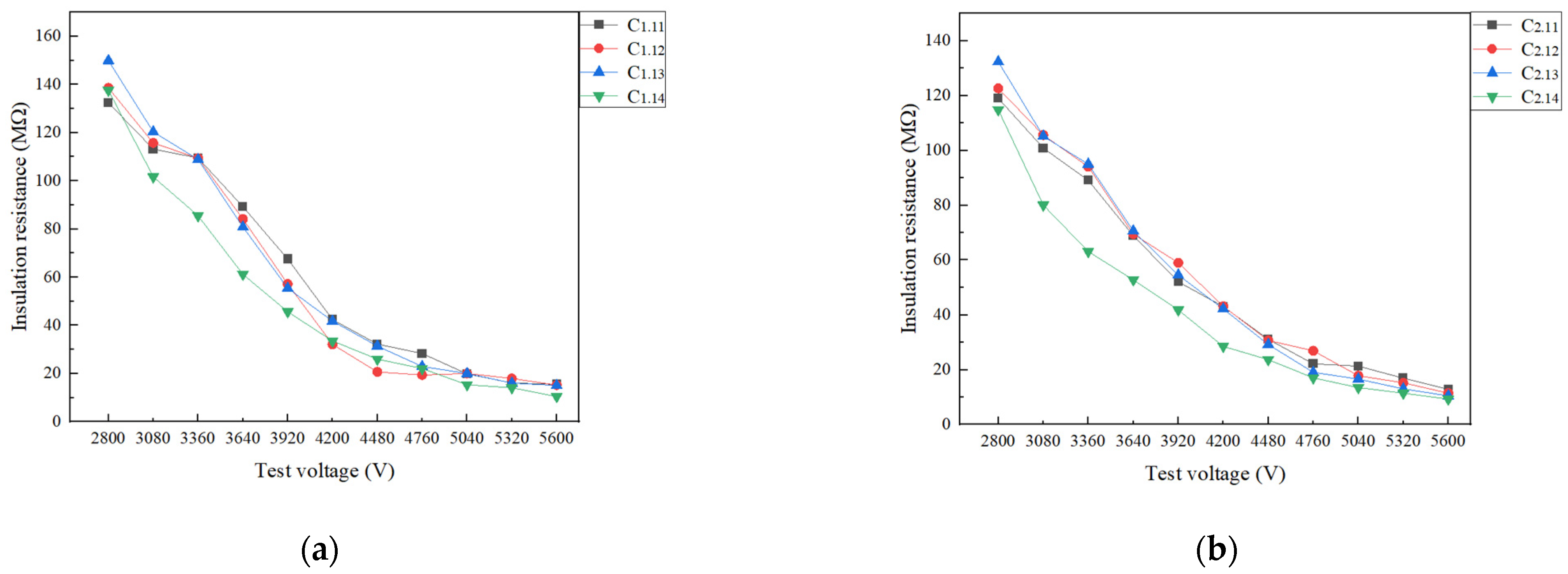
In the cases of HST = 105 °C or 110 °C, the insulation resistance values of the samples rapidly decrease with the growth of the initial discharge voltage values. When the initial discharge voltage reaches 4480 V (i.e., 1.6 UNDC), the process of decreasing insulation resistance values slows down. This is essentially due to the fact that for high levels of the initial discharge voltage, some weak self-healing occurs in the sample and the leakage current increases. However, in the case of occurring self-healing, the insulation resistance value of the sample gradually decreases.
(2)
Concerning the case of HST = 105 °C, when the initial discharge voltage value is the rated operating voltage, the insulation resistance of the samples with WTC = 1.6 exhibited the largest level, and the insulation resistance of the samples with WTC = 1.4 exhibited the smallest level.
(3)
Concerning the case of HST = 110 °C, when the initial discharge voltage is set as the nominal operating voltage, the insulation resistance value of the samples with WTC = 1.6 exhibits the largest value, and the insulation resistance value of the samples with WTC = 1.7 reaches its smallest level.
(4)
As the HST of the samples rises from 105 °C to 110 °C, the insulation resistance values of the samples lessen for all considered WTCs.
Commonly, the insulation resistance depends on the material properties, operating temperature, and field strength of the capacitor. Up till now, investigations on the MPFC insulation resistance have been mainly focused on capacitor conductance, and almost no investigation has been devoted to their quantitative studies.

4.3. Withstand Voltage Test

The test for withstand voltage using a stepwise voltage increase was conducted on samples in the presence of two HSTs and four WTCs. After the voltage withstand test was carried out at each step, both the capacitance of the capacitor and the tangent of the loss angle were appropriately measured. The average value of the samples was then taken to assess the relationship curves of the capacitance change rate and the tangent of the loss angle with the test voltage. Figure 10 and Table 5 illustrate the relationship curves of the capacitance change rate and the tangent of the loss angle in terms of the test voltage at the HST of 105 °C. Additionally, Figure 11 and Table 6 include the relationship curves of the capacitance change rate and the tangent of loss angle values as a function of the test voltage at the HST of 110 °C.
According to Figure 10 and Table 5, in the case of HST = 105 °C, the samples with WTC = 1.6 (which corresponds to a tension of 1440 gf) have the best ability to withstand voltage. In such a case, the breakdown voltage of the samples is obtained to be 7000 V. In addition, the samples with WTC = 1.4 (corresponding to the tension of 1260 gf) exhibit the worst ability to withstand the voltage, and the breakdown voltage of the samples is predicted to be 6720 V.
From Figure 11 and Table 6, in the case of HST = 110 °C, the samples with WTC = 1.6 possess the best ability to withstand the voltage, and the breakdown voltage of the samples is 7280 V. Further, the samples with WTC = 1.7 (corresponding to the tensile strength of 1530 gf) possess the worst ability to withstand the voltage, and the breakdown voltage of the samples is obtained as 7000 V.
From the test data, it can also be seen that the HST is capable of improving the withstand voltage capability of DCLCs, leading to an increase in the temperature by 5 °C and the breakdown voltage shows an increase of 4% (7000 V at 105 °C or 7280 V at 110 °C). However, the tension coefficient is not proportional to the DCLC voltage withstand capability.
Currently, the breakdown voltage test is not conducted on the MPFC itself, but mainly on the metalized film or polypropylene film. A perpendicular stress is applied to the flat-lying film, which differs from the mechanical stress applied to the element [18,27]. In Ref. [18], the dielectric breakdown strength was obtained as 600 V/μm at 0 MPa interlayer pressure, while it was reported to be 257 V/μm at 1 Mpa interlayer pressure. In Ref. [27], the DC withstand strength of the surface-grafted PP membranes reached 551.2 kV/mm. In the present investigation, the breakdown voltage was obtained as 7000 V at 105 °C or 7280 V at 110 °C, and the corresponding breakdown field strength was obtained as 583.3 V/μm at 105 °C or 606.67 V at 110 °C. The test results are better than the comparative tests. Therefore, the results of this study can be still regarded as an appropriate reference work for future explorations.

5. Conclusions

This study focused on examining the impact of mechanical stress on the metalized polypropylene film capacitors (DCLCs). The winding tension and heat-setting shrinkage tension of the elements were considered as the main factors affecting mechanical stress. Different winding tension coefficients (WTCs) and heat-setting temperatures (HSTs) were implemented in the production of the elements. Then accelerated aging test, insulation resistance measurement, and withstand voltage test were performed on these DCLCs. The effects of mechanical stress on the DCLC life and insulation performance were methodically analyzed and explained. The main obtained results can be summarized as follows:
(1)
The capacitance of the samples with four WTCs at the HSTs of 105 °C and 110 °C increased and then decreased with time.
(2)
Shrinkage tension during heat setting affected the service life of the samples such that their life improved with raising of the temperature. When the HST increased from 105 °C to 110 °C, the capacitance changes of all four winding tensions (tension coefficients) exhibited a descending trend accordingly after 800 h of the life aging test.
(3)
The winding tension influenced the life of the samples such that those with the highest tension (tension coefficient) exhibited the longest life at HST = 105 °C, whereas the samples with the lowest tension exhibited the longest life at HST = 110 °C. In the case of HST = 105 °C, the samples with WTC = 1.7 exhibited the lowest capacitance change (−1.985%) after 800 h of the aging test. In the case of HST = 110 °C, the samples with WTC = 1.4 had the lowest capacitance change rate (−0.915%) after 800 h of the life aging test.
(4)
Shrinkage tension during heat setting affected the tangent of the loss angle of DCLCs. When the HST was raised from 105 °C to 110 °C, all tangent values of the loss angle of the samples with four types of WTCs were reduced compared to before the test after 800 h of the life aging test.
(5)
When the temperature of the heat setting increased from 105 °C to 110 °C, all the insulation resistance values of the samples with four kinds of WTCs were reduced. When the initial discharge voltage was set at the rated operating voltage, the insulation resistances of the samples with WTC = 1.6 had the largest value.
(6)
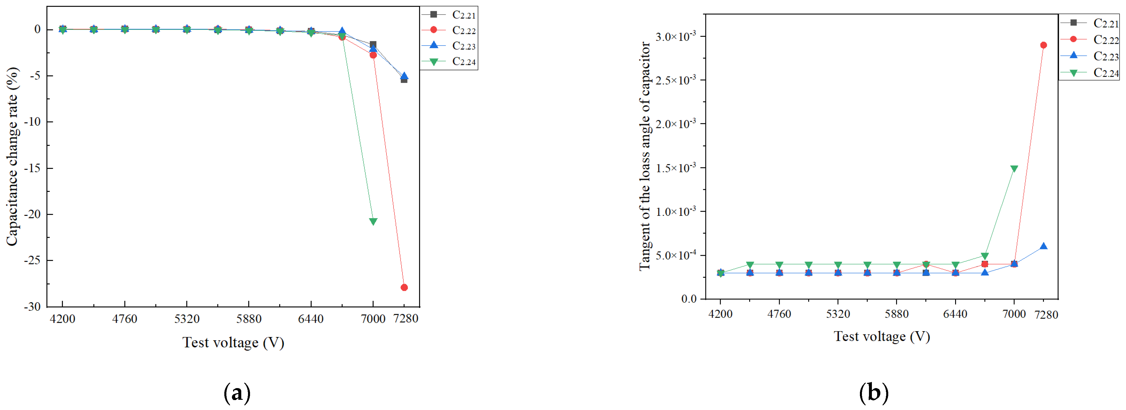
The samples with WTC = 1.6 exhibited the best ability to withstand voltage, and the breakdown voltage of the samples was obtained as 7000 V at HST = 105 °C or 7280 V at HST = 110 °C.
The findings suggest that the mechanical stresses, dominated by the winding tension and heat-setting shrinkage of elements, affect the life and insulation characteristics of DCLCs. These results can be utilized to analyze and solve problems associated with mechanical stress, insulation performance, and DCLCs in the field of metalized polypropylene film capacitors.

Author Contributions

X.S. put forward the idea and analyzed the data. X.S. and Y.L. carried out the experiments and wrote the paper, and X.G. and C.C. assisted in completing the experiment. Y.Q. analyzed the mechanism. All authors have read and agreed to the published version of the manuscript.

Funding

This study is supported by the Key R&D (Industry Foresight and Key Core Technologies) Projects in Jiangsu Province (grant No. BE2021038), and the science and technology program of Jiangsu Province (grant No. BM2023533).

Data Availability Statement

Data is contained within the article.

Conflicts of Interest

Authors Xiaowu Sun, Yinda Li, Xiangming Guo and Chongfeng Cao were employed by the company Wuxi Power Filter Co., Ltd. The remaining author declares that the research was conducted in the absence of any commercial or financial relationships that could be construed as a potential conflict of interest.

References

  1. Rytöluoto, I.; Niittymäki, M.; Seri, P.; Naderiallaf, H.; Lahti, K.; Saarimäki, E.; Flyktman, T.; Paajanen, M. Biaxially oriented silica–polypropylene nanocomposites for HVDC film capacitors: Morphology-dielectric property relationships, and critical evaluation of the current progress and limitations. J. Mater. Chem. A 2022, 10, 3025–3043. [Google Scholar] [CrossRef]
  2. Makdessi, M.; Sari, A.; Venet, P. Metallized polymer film capacitors ageing law based on capacitance degradation. Microelectron. Reliab. 2014, 54, 1823–1827. [Google Scholar] [CrossRef]
  3. Rabuffi, M.; Picci, G. Status quo and future prospects for metallized polypropylene energy storage capacitors. IEEE Trans. Plasma Sci. 2002, 30, 1939–1942. [Google Scholar] [CrossRef]
  4. Sarjeant, W.J.; Zirnheld, J.; MacDougall, F.W.; Bowers, J.; Clark, N.; Clelland, I.; Price, R.; Hudis, M.; Kohlberg, I.; McDuff, G. Capacitors—Past, present, and future. In Handbook of Low and High Dielectric Constant Materials and Their Applications; Elsevier: Amsterdam, The Netherlands, 1999; pp. 423–491. [Google Scholar]
  5. Wang, H.; Blaabjerg, F. Reliability of capacitors for DC-link applications in power electronic converters—An overview. IEEE Trans. Ind. Appl. 2014, 50, 3569–3578. [Google Scholar] [CrossRef]
  6. Lv, C.; Liu, J.; Zhang, Y.; Yin, J.; Cao, R.; Li, Y.; Liu, X. A method to characterize the shrinking of safe operation area of metallized film capacitor considering electrothermal coupling and aging in power electronics applications. IEEE Trans. Ind. Electron. 2022, 70, 1993–2002. [Google Scholar] [CrossRef]
  7. Du, B. Polymer Insulation Applied for HVDC Transmission; Springer Nature: Berlin/Heidelberg, Germany, 2020. [Google Scholar]
  8. Xing, Z.; Gu, Z.; Zhang, C.; Guo, S.; Cui, H.; Lei, Q.; Li, G. Influence of space charge on dielectric property and breakdown strength of polypropylene dielectrics under strong electric field. Energies 2022, 15, 4412. [Google Scholar] [CrossRef]
  9. Tai, Y.; Chen, P.; Jian, Y.; Fang, Q.; Xu, D.; Cheng, J. Failure mechanism and life estimate of metallized film capacitor under high temperature and humidity. Microelectron. Reliab. 2022, 137, 114755. [Google Scholar] [CrossRef]
  10. Li, Z.; Li, H.; Qiu, T.; Lin, F.; Wang, Y. Reliability criterion of film capacitor based on moisture diffusion in encapsulation. High Volt. 2023, 8, 1242–1252. [Google Scholar] [CrossRef]
  11. Wang, H.; Nielsen, D.A.; Blaabjerg, F. Degradation testing and failure analysis of DC film capacitors under high humidity conditions. Microelectron. Reliab. 2015, 55, 2007–2011. [Google Scholar] [CrossRef]
  12. Hu, Y.; Ye, X.; Zheng, B.; Zhao, Z.; Zhai, G. Degradation mechanisms-based reliability modeling for metallized film capacitors under temperature and voltage stresses. Microelectron. Reliab. 2022, 138, 114609. [Google Scholar] [CrossRef]
  13. Cheng, L.; Li, Z.; Wang, J.; Xu, Z.; Liu, W.; Li, S. Degradation behavior and mechanism of metalized film capacitor under ultrahigh field. IEEE Trans. Dielectr. Electr. Insul. 2023, 30, 509–517. [Google Scholar] [CrossRef]
  14. Petersson, L.; Wei, K.; Paulsson, G.; Strömsten, D.; Ekh, J. Mechanical stress distribution inside Dry capacitor elements. In Proceedings of the Nordic Insulation Symposium, Trondheim, Norway, 9–12 June 2013. [Google Scholar]
  15. Peng, B.; Lin, F.; Li, H.; Chen, Y.; Zhang, M.; Lv, F. Calculation and measurement of metalized film capacitor’s inner pressure and its influence on self-healing characteristics. IEEE Trans. Dielectr. Electr. Insul. 2010, 17, 1612–1618. [Google Scholar] [CrossRef]
  16. Tandon, S. Modeling of Stresses in Cylindrically Wound Capacitors: Characterization and the Influence of Stress on Dielectric Breakdown of Polymeric Film; University of Massachusetts Amherst: Amherst, MA, USA, 1997. [Google Scholar]
  17. Tandon, S.; Farris, R.J. Metalized polypropylene film in capacitors: Characterization and the effect of interfacial pressure on the dielectric srength. MRS Online Proc. Libr. 1997, 476, 147. [Google Scholar] [CrossRef]
  18. Rytöluoto, I.; Lahti, K. Effect of inter-layer pressure on dielectric breakdown characteristics of metallized polymer films for capacitor applications. In Proceedings of the 2013 IEEE International Conference on Solid Dielectrics (ICSD), Bologna, Italy, 30 June 2013–4 July 2013; pp. 682–687. [Google Scholar]
  19. Wang, Z.; Qi, C.; Yan, F.; Ma, Y. Study on DC surface flashover at the clear edge of metallized polypropylene films. IEEE Trans. Plasma Sci. 2022, 50, 3139–3147. [Google Scholar] [CrossRef]
  20. Wang, Z.; Xie, S.; Yan, F.; Yang, Y.; Ma, Y. Design of current gate width in AC segment metalized film capacitors based on self-healing characteristics. IEEE Trans. Plasma Sci. 2023, 51, 2688–2696. [Google Scholar] [CrossRef]
  21. Cui, H.; Xing, Z.; Zhang, C.; Guo, S.; Su, Y.; Zhang, H. Characteristic evaluation of BOPP capacitor after winding process with mechanical stress. In Proceedings of the 2023 IEEE 4th International Conference on Electrical Materials and Power Equipment (ICEMPE), Shanghai, China, 7–10 May 2023; pp. 1–4. [Google Scholar]
  22. Wang, W.; Li, H.; Li, Z.; Tong, Y.; Lin, F. Life time improvement of metalized film capacitors by inner pressure strengthening. High Power Laser Part. Beams 2014, 26, 045015. [Google Scholar] [CrossRef]
  23. IEC 61071:2017; Capacitors for Power Electronics. IEC: London, UK, 2017.
  24. Ran, Z.; Du, B.; Xiao, M.; Li, J. Crystallization morphology-dependent breakdown strength of polypropylene films for converter valve capacitor. IEEE Trans. Dielectr. Electr. Insul. 2021, 28, 964–971. [Google Scholar] [CrossRef]
  25. Du, B.; Ran, Z.; Liu, H.; Xiao, M. Research progress ofdielectric properties and improvement methods of polypropylene filmfor dry-type capacitor. Trans. China Electrotech. Soc. 2023, 38, 1363–1374. [Google Scholar]
  26. Wang, Y.; Li, H.; Wang, Z.; Lin, F. Voltage maintaining performance of metallized film capacitors based on crystallinity regulation. High Volt. Eng. 2022, 48, 3643–3650. [Google Scholar]
  27. Liu, H.; Du, B.; Xiao, M.; Tanaka, T. High-temperature performance of dielectric breakdown in BOPP capacitor film based on surface grafting. IEEE Trans. Dielectr. Electr. Insul. 2021, 28, 1264–1272. [Google Scholar] [CrossRef]
Figure 1. Structure of an element.
Energies 17 00699 g001
Figure 2. Schematic representation of the heat-setting effect.
Energies 17 00699 g002
Figure 3. Winding process of the DCLC.
Energies 17 00699 g003
Figure 4. Schematic representation of the sample capacitor.
Energies 17 00699 g004
Figure 5. Photos of the equipment for the life aging test: (a) thermostat and DC power supply, (b) LCR meter.
Energies 17 00699 g005
Figure 6. Schematic representation of the experimental circuit.
Energies 17 00699 g006
Figure 7. Results of the life test of various winding tensions at HST = 105 °C: (a) capacitance change rate, (b) tangent value of the loss angle of the capacitor.
Energies 17 00699 g007
Figure 8. Results of the life test of various winding tensions at HST = 110 °C: (a) capacitance change rate, (b) tangent of the loss angle of the capacitor.
Energies 17 00699 g008
Figure 9. Insulation resistance in terms of the initial discharge voltage in the presence of various winding tensions: (a) HST = 105 °C, (b) HST = 110 °C.
Energies 17 00699 g009
Figure 10. Test results of the withstand voltage in the presence of various WTCs at HST = 105 °C: (a) capacitance change rate, (b) tangent of the loss angle.
Energies 17 00699 g010
Figure 11. Test results of the withstand voltage in the presence of various WTCs at HST = 110 °C: (a) capacitance change rate, (b) tangent of the loss angle.
Energies 17 00699 g011
Table 1. Capacitance change rates of various winding tensions at HST = 105 °C.
SamplesC1.1C1.2C1.3C1.4
Time (h)100500800100500800100500800100500800
Capacitance change rate (%) 0.022−1.458−3.440−0.011−1.692−7.2450.044−0.608−2.2390.056−0.502−1.985
Table 2. Capacitance change rates of various winding tensions at HST = 110 °C.
SamplesC2.1C2.2C2.3C2.4
Time (h)100500800100500800100500800100500800
Capacitance change rate (%) 0.040−0.281−0.915−0.006−0.414−1.3910.071−0.290−2.1200.052−0.209−1.693
Table 3. Insulation resistances of various samples at HST = 105 °C.
SamplesC1.11C1.12C1.13C1.14
Voltage (V)280044805600280044805600280044805600280044805600
Insulation resistance (MΩ)132.4432.2715.52138.5920.7215.23149.9531.4615.13137.6226.0210.49
Table 4. Insulation resistances of various samples at HST = 110 °C.
SamplesC2.11C2.12C2.13C2.24
Voltage (V)280044805600280044805600280044805600280044805600
Insulation resistance (MΩ)119.0131.1112.85122.6430.7011.45132.3416.9410.50114.8223.679.29
Table 5. Capacitance change rates of various samples at HST = 105 °C.
SamplesC1.21C1.22C1.23C1.24
Voltage (V)67206720672070006720
Capacitance change rate (%)−20.99−0.554−2.357−14.06−1.517
Table 6. The capacitance change rates of various samples at HST = 110 °C.
SamplesC2.21 C2.22C2.23C2.24
Voltage (V)7000728070007280700072807000
Capacitance change rate (%)−1.6−5.386−2.73−27.88−2.11−5.04−20.65
Disclaimer/Publisher’s Note: The statements, opinions and data contained in all publications are solely those of the individual author(s) and contributor(s) and not of MDPI and/or the editor(s). MDPI and/or the editor(s) disclaim responsibility for any injury to people or property resulting from any ideas, methods, instructions or products referred to in the content.

